

Page 1

Flash Sequencer
Owner’s Manual
Revision 1.0
Copyright 2011 Cognisys, Inc.
1
Page 2

Table of Contents
1. SAFETY INSTRUCTIONS .................................................................................................................................. 3
2. GETTING STARTED ......................................................................................................................................... 3
2.1 PACKAGE CONTENTS .......................................................................................................................................... 3
2.2 CONNECTIONS .................................................................................................................................................. 3
3. OPERATION ................................................................................................................................................... 6
3.1 OVERVIEW ....................................................................................................................................................... 6
3.2 CONFIGURING STOPSHOT ................................................................................................................................... 6
3.3 INDICATORS ..................................................................................................................................................... 9
3.4 RESET ............................................................................................................................................................. 9
3.5 MICROPHONE USAGE ...................................................................................................................................... 10
4. CONNECTIONS & CABLES ............................................................................................................................. 10
4.1 TRIGGER OUTPUTS .......................................................................................................................................... 10
4.2 ACTIVATING RELAYS......................................................................................................................................... 11
5. TROUBLESHOOTING .................................................................................................................................... 12
6. SPECIFICATIONS .......................................................................................................................................... 12
7. WARRANTY ................................................................................................................................................. 14
8. GLOSSARY ................................................................................................................................................... 15
9. REVISION HISTORY ...................................................................................................................................... 16
Table of Figures
Figure 1 - Typical Connection Diagram ......................................................................................................... 4
Figure 2 - RCA connector ............................................................................................................................ 11
Figure 3 - Wiring an external relay .............................................................................................................. 12
2
Page 3

1. Safety Instructions
WARNING indicates a potentially hazardous situation which, if not avoided, could result in death
or serious injury.
Follow all CAUTION notices to reduce the risk of personal injury, prevent damage to the
StopShot module, accessories, and devices (cameras, flashes, etc). Failure to follow all CAUTION
notices may void your warranty. CAUTION may also indicate a potentially hazardous situation
which, if not avoided, may result in personal injury.
The safety alert symbol precedes a general CAUTION or WARNING statement.
The electrical hazard symbol precedes an electric shock hazard CAUTION or WARNING
statement.
2. Getting Started
2.1 Package contents
The latest version of this manual is available at
Your Flash Sequencer package contains the following:
1. Flash Sequencer Module (1)
2. 6 ft - 3.5mm M/M Cable
3. (2) - 6 ft – RCA M/M Cable
4. PC→RCA Cable
You will need one PC→RCA cable and one 6 ft RCA cable for each flash that you intend to use with the
sequencer.
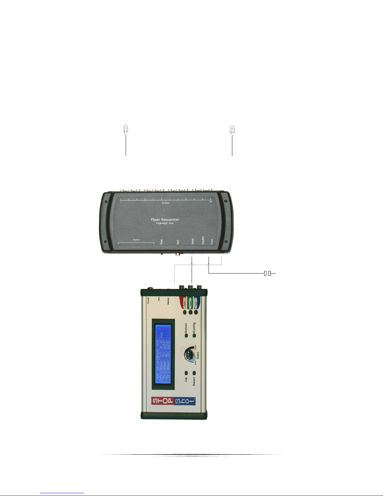
2.2 Connections
http://www.cognisys-inc.com.
To connect the flash sequencer to StopShot use the included 3.5mm cable and connect one end to the
jack labeled “Sensor” on StopShot and the other end of the cable to the “StopShot” jack on the
sequencer. Sensors traditionally inserted into StopShot will now be plugged into the sequencer. This
allows the sequencer to draw power from StopShot.
3
Page 4
Flash 1
Flash 12
. . . . . . .
Sensor
(Beam, Vibe, etc.)
The included six foot RCA cable should be plugged into the desired StopShot trigger output and then be
connected to the sequencer’s “Input” jack. StopShot provides the timing signals required by the
sequencer.
PC to RCA cables coupled with a six foot RCA cable are then attached to the sequencers “Output” jacks.
See Figure 1 below for a typical connection diagram.
Figure 1 - Typical Connection Diagram
4
Page 5

WARNING: High voltage flashes should NOT be connected to the sequencer or any of its associated
adapters/connectors/cables. Doing so could expose you to dangerously high voltages resulting in
serious injury or death. All new flashes on the market do not expose high voltage on the hot-shoe.
These are the flashes intended for use with the sequencer. Please visit our web-site at
http://www.cognisys-inc.com for a list of low-voltage flashes, or contact us via e-mail at:
support@cognisys-inc.com.
CAUTION: Do not use “Y” adapters for the trigger outputs to connect more than three devices.
Some devices generate significant transients (like solenoids) that may damage sensitive equipment such
as cameras and flashes. The sequencer is protected from these transients but other electronics (such as
flashes and cameras) may not be. It is acceptable to use a “Y” adapter to connect more than one device
to a trigger output as long as the devices are similar. If you have any questions or concerns about device
compatibility, please contact us at:
support@cognisys-inc.com.
5
Page 6

3. Operation
>
T1 Mode:
Trigger
# Pulse:
1 TPulse1:
500.0 ms
Toff1:
100.0 ms ->
3.1 Overview
The Flash Sequencer enables StopShot to expand its output capability. StopShot can generate
multiple output pulses for each of its three trigger outputs. When coupled with the sequencer,
up to three variable length pulses can be generated and up to 1000 fixed length pulses! What
does this mean? Each pulse can activate a flash, water valve, or other device. This allows for
fantastic stroboscopic effects, water cascades, motion sequences, etc.
3.2 Configuring StopShot
From StopShot’s main screen press the SELECT button until the cursor is next to the “trigger”
output you want to change. Press the CONFIG button. This will bring up the output
configuration screen. This screen enables each trigger output to be configured in a different
way by changing the parameters described below. We will use the example of a “trigger” mode,
but the sequencer may be used with every mode in StopShot.
Press the SELECT button until the indicator is next to “# Pulse”. This is the number of pulses that
StopShot will generate when this trigger is activated. If desired output is selected, press the
CONFIG button. This will bring up the Timer Configuration screen. Press the UP/DOWN
buttons until the “T Mode” is changed to “Trigger”.
In this trigger mode you have additional options to modify (if required).
6
Page 7

>
Pulse2:
Same
Toff2:
Same
Pulse3+:
Same
Toff3+:
Same ->
# Pulse:
The number of pulses (“# Pulse”) may be set to a value greater than one if multiple trigger
output pulses are required. This may be used to generate multiple events (firing multiple
flashes). If this value is set to one then each “input” to StopShot would cause the sequencer to
advance to the next output. If set to greater than one then multiple outputs will be generated
to the sequencer.
Pulse1:
You have the option of adjusting the first output pulse that is generated. This is the “Pulse1”
field. The default is 500ms, but may be adjusted as necessary for your application. Some loads
may have a minimum pulse time before they will trigger. For electro-mechanical devices such as
a relay controlling a solenoid, you may need to increase this time. Cameras and flashes are
generally edge sensitive so they can be set considerably faster than the 500ms default. This
duration may be adjusted to “Latch” for sequential mode (See your StopShot manual for
details). Note: Some devices such as flashes are “edge-sensitive”, that is, they fire when the
output transitions. Increasing the duration of “Pulse1” has no effect on these types of devices
because they only trigger on the transition. Devices like relays, water valves, and solenoids are
“level-sensitive” in that they will remain active for the duration of the pulse.
Toff1:
“Toff” is used as the off-time after “Pulse1”’s on time has expired provided the number of pulses
is greater than one. This allows complete flexibility for the on and off duration of the output.
Pulse2:
Pressing the SELECT button through the bottom of the first configuration page will reveal a
second list of configurations:
When the number of desired pulses on an output (See “# Pulse” above) is set to greater than
one, you have the option of choosing the second pulse to be a different duration than the first.
StopShot defaults to “Same”, meaning that the second pulse after the first will be the same as
the “TPulse1” duration. You can use the UP or DOWN button to adjust the timing of “Pulse2”. If
you want to return back to “Same”, hold the DOWN button continuously until the time counts
down. Eventually “Same” will be displayed and the time of “TPulse2” will again track the
duration of “TPulse1”.
7
Page 8

Toff2:
>
Incrm:
Off Blank:
Off
->
T1 Mode:
Trigger
# Pulse:
1
>
Pulse1:
500.0 ms
Toff1:
100.0 ms ->
“Toff2” is the duration the second output pulse remains off following “Pulse2”.
Pulse3+:
If “# Pulse” is three or greater the value of “Pulse3+” will control the on time of the trigger
output. It functions similarly to “Pulse2” but controls the third and all future pulses. “# Pulse”
must be set to a value of three or greater for this to have any effect.
Toff3+:
Similarly to “Toff2”, this controls the off time for the third and future pulses. “# Pulse” must be
set to a value of three or greater for this to have any effect.
Incrm:
Pressing the SELECT button will reveal the third and final trigger configuration. This timer mode
has the option to automatically increment the timer’s main delay every time an event occurs by
adjusting the “Incrm” configuration. If an event is easily repeatable and this increment is set
you can create a simulated “time lapse” for some quickly occurring event (like a drop of water
falling).
If this value is set to 10.0 ms, and from the main screen the trigger output is set to 100.0 ms,
every time a trigger occurs the delay would increase by 10ms. The delay setting will be updated
on the main screen following each trigger event. The first time the trigger would wait 100 ms.
The second: 110 ms. The third: 120 ms. Every time StopShot activates the trigger output the
delay on the main screen will be incremented by the “Incrm” value. If you want to start the
sequence over simply adjust the trigger output value on the main screen back to its original
value using the UP/DOWN buttons.
Blank:
Additionally, you can adjust “Blank”, which is the amount of time that the input is ignored after
the output pulse is complete. Let’s say the following settings are used:
8
Page 9

Incrm:
Off > Blank:
200.0 ms
->
== Global Config ==
LCD Backlight: 10
Pwr Toff: 250.0 ms ->
>
In this example, “Pulse” is set to 500ms, and “Blank” is set to 200ms. When an input event
occurs (for example, a beam sensor being crossed), the trigger output will delay by whatever
value is entered on the main screen, generate a 500ms pulse, and then wait 200ms before
looking for an input again. “Blank” is useful for ignoring all but the first of a series of rapidly
occurring events.
Blanking time must be set to a minimum of 50ms if “# Pulse” is set to “1” to prevent the
transient caused by the load (flash, valve, etc) from causing StopShot to re-trigger on the
transient. If you see StopShot continually triggering and the sequencer rapidly advancing
through states then please verify that “Blank” is set to at least 50ms.
3.3 Indicators
The LED lights on the side of the flash sequencer below the “Active” text indicate which output
will fire next. Upon applying power, the first indicator will be illuminated showing that “Output
1” will fire next. As StopShot applies pulses to the sequencer’s “Input”, the LED lights will
progress to keep you informed what state the sequencer is in.
3.4 Reset
The Reset button is provided as a method to manually reset the sequencer to the first output. If
StopShot generates three pulses, the sequencer will have advanced from “Output 1” to “Output
4”. If you want to restart at “Output 1”, you can push the Reset button.
By adjusting parameters in StopShot, you can also have StopShot reset the sequencer for you.
This will only be functional if the flash sequencer is connected to the sensor jack of StopShot
(not externally powered). This is accomplished by using the “Power Disable” feature. By
holding down the CONFIG button on StopShot until “Global Configuration” is entered, press the
SELECT button until the indicator is next to “Pwr Off”:
Pwr Off: None
Using the UP or DOWN buttons, adjust “Pwr Off” until it displays the trigger configuration that
should reset the sequencer when complete.
9
Page 10

Let’s say that the sequencer is connected to the “Trigger 1” output of StopShot, and a beam
== Global Config ==
LCD Backlight: 10
Pwr Toff: 250.0 ms ->
>
sensor is connected to the flash sequencer (daisy-chained to StopShot through the sequencer).
StopShot is configured for a global mode of “Sequential”, and “Trigger 1” is set to generate
three pulses, and the main screen delay is set to 315ms. We don’t want to disable the power
when “Trigger 1” is activated, since the moment the beam sensor would be crossed the
sequencer would be powered off. In this scenario, “Trigger 2” of StopShot would be configured
as “Delay 2”. The main-screen delay value is not important for “Delay 2” since the moment
“Trigger 1” completes “Delay 2” is active and the power will be disabled. Now the global
configuration “Pwr Off” would be changed to:
Pwr Off: Trig 2
This way when “Trig 2” is active (which we configured as “Delay”) the sequencer will be turned
off. When power is re-applied automatically after the 250ms “Pwr Toff” time expires, the
sequencer will once again be at “Output 1”.
3.5 Microphone Usage
A microphone may still be used with the flash sequencer. The flash sequencer will still need to
draw power from StopShot via the “Sensor” connection. When using a microphone, plug it into
the “Mic” jack on StopShot, and also have the 3.5mm cable from StopShot to the flash
sequencer to provide power.
4. Connections & Cables
One of the design goals of StopShot was to make it simple to add cable extensions and do
custom wiring. Nothing is more frustrating than buying a product and finding out that it uses
over-priced proprietary cables. All StopShot cables are available at your favorite audio/video
equipment supply store. We provide the connection diagrams below so that you have the
option of making custom cables or sensors. If you have any questions, please contact us at
support@cognisys-inc.com.
4.1 Trigger Outputs
All the trigger outputs use standard “RCA” jacks. RCA extensions come in all different types,
one end as male and the other as female. There are mono (single) extensions which are
typically used for video. Stereo/dual extensions are usually for extending audio connections.
There are triple extensions for extending audio and video equipment. You also have the option
of buying standard RCA cables and using a coupler adapter to connect two male/male cables
together.
10
Page 11

Sequencer Output
Outside RCA terminal
Inside RCA terminal
As with all RCA jacks the outside connector is ground. The flash sequencer’s outputs are “Low
Side Drivers” (switches in ground). This means that when a output fires, it connects the center
conductor of the RCA jack to the outside connector (ground) to draw current through the
center conductor.
See Figure 2 below for a wiring diagram for the RCA connectors.
Figure 2 - RCA connector
4.2 Activating Relays
Some applications require activating a relay to enable (or disable) a “load”. Relays allow
StopShot to turn on/off a variety of AC and DC devices.
CAUTION: Care should be taken when wiring the flash sequencer to control AC or high-
voltage DC as a mistake in wiring the relay could cause damage to the unit and other connected
devices.
See Figure 3 below as an example of wiring the sequencer to control a 12V DC relay.
11
Page 12

StopShot Output
12V Battery or
wall transformer
Relay Coil
Relay Contacts
Outside RCA terminal
Load
Wiring a Relay to the flash Sequencer
(Low Side Switch)
Inside RCA terminal
All grounds connected together
Blanking time not set
If “# pulse” is set to “1”, you
5. Troubleshooting
Problem Cause Solution
“Output 1” indicator not lit 3.5mm cable not connected to
Sequencer advances on its
own.
Figure 3 - Wiring an external relay
Connect the cable and verify
StopShot “Sensor” jack
that StopShot is powered. Be
sure it is in the “Sensor” jack
and not “Mic”.
Poor 3.5mm cable connection Verify the cable is plugged
into StopShot properly.
MUST set the blanking time to
a minimum of 50ms.
If you cannot resolve a problem with your flash sequencer, please contact us at
support@cognisys-inc.com. We want to make sure that you are completely satisfied with our
product.
6. Specifications
12
Page 13

Specifications are intended for reference only. The design may be modified to improve features or functionality
Specifications
MIN
NOM
MAX
UNITS
Input Voltage
3
4.5
14
Vdc
Output Current Sink
- - 1
Adc
Sensor Supply Output Voltage
4.0
4.5
5.0
Vdc
Sensor Supply Output Current
- - 100
mAdc
Max Voltage on Output (Steady State)
- - 60
Vdc
Operating Temperature
-20
25
50
C
without notice.
20ns Response Time
•
• 12 Outputs
• Cascaded/Stackable design allows multiple sequencers to be used (daisy chaining)
13
Page 14

7. Warranty
Limited Warranty
All products are warranted to be free from defects in materials or workmanship for one (1) year
from the date of purchase. Within this period, Cognisys Inc. will, at its sole option, repair or
replace any components which fail in normal use. Such repairs or replacement will be made at no
charge to the customer for parts or labor, provided that the customer shall be responsible for any
transportation cost. This warranty does not cover failures due to abuse, misuse, accident or
unauthorized alterations or repairs.
THE WARRANTIES AND REMEDIES CONTAINED HEREIN ARE EXCLUSIVE AND IN
LIEU OF ALL OTHER WARRANTIES, WHETHER EXPRESS, IMPLIED OR STATUTORY,
INCLUDING ANY LIABILITY ARISING UNDER ANY WARRANTY OF
MERCHANTABILITY OR FITNESS FOR A PARTICULAR PURPOSE, STATUTORY OR
OTHERWISE. THIS WARRANTY GIVES YOU SPECIFIC LEGAL RIGHTS, WHICH MAY
VARY FROM STATE TO STATE.
IN NO EVENT SHALL COGNISYS BE LIABLE FOR ANY INCIDENTAL, SPECIAL,
INDIRECT OR CONSEQUENTIAL DAMAGES, WHETHER RESULTING FROM THE USE,
MISUSE OR INABILITY TO USE THE PRODUCT OR FROM DEFECTS IN THE
PRODUCT. SOME STATES DO NOT ALLOW THE EXCLUSION OF INCIDENTAL OR
CONSEQUENTIAL DAMAGES, SO THE ABOVE LIMITATIONS MAY NOT APPLY TO
YOU.
Cognisys retains the exclusive right to repair or replace the product or offer a full refund of the
purchase price at its sole discretion. SUCH REMEDY SHALL BE YOUR SOLE AND
EXCLUSIVE REMEDY FOR ANY BREACH OF WARRANTY.
14
Page 15

8. Glossary
Term
Description
# Pulse
Number of output pulses that a trigger output will generate.
Blank
The blanking time is the duration where StopShot will ignore the input. This
may be useful to ignore second drops, transients, or flashes.
Latched
When an output stays in a given state (on or off).
ms
Abbreviation for milliseconds. A thousandth of a second (1/1000 seconds).
Pwr Off
Power-Off. This lets you choose which trigger output will disable the sensor
mode where they all function at the same time.
TMode
Trigger Mode. This is a global configuration that lets you choose the
output after a configurable delay after seeing an input.
Trigger Output
One of the three outputs of StopShot. The Red LED’s correspond to the
Incrm Abbreviation for increment. The increment value will be added to the delay
setting every time there is an input event.
Independent A global triggering mode where all the triggers operate independent from
each other.
power. The moment an event is detected the power will be turned off. This
is useful for eliminating red laser light from being in pictures. You can
choose from no outputs, all of them, or each individual output to cause the
disabling of the power.
Pwr Toff Power Time Off. This is the duration that the sensor power will be disabled.
SEQ The global configuration is set to “Sequential Mode”. This means that the
trigger configurations will follow in sequence. The opposite is independent
Sequential A global triggering mode where the triggers operate sequentially. That
means that the following trigger won’t start until the current one completes.
Short Circuit (short) To connect two wires together. Provide a path for current to flow with low
resistance.
behavior of StopShot. Examples are: Independent, Sequential, Time Lapse,
Flash measurement, etc...
Toff The time off between output pulses.
Trigger When one of the three channels is configured as “Trigger”, it will fire the
three outputs.
us Abbreviation for microseconds. A millionth of a second.
15
Page 16

Revision
Date
Change
1.0
05/08/11
Initial Release
9. Revision History
16
 Loading...