

Page 1

MX-1502
Reference Manual
09/08/2017
Version: 5.7.1.51
Page 2

Legal Notices
The software described in this document is furnished under license, and may be used or copied only in accordance with
the terms of such license and with the inclusion of the copyright notice shown on this page. Neither the software, this
document, nor any copies thereof may be provided to, or otherwise made available to, anyone other than the licensee.
Title to, and ownership of, this software remains with Cognex Corporation or its licensor. Cognex Corporation assumes
no responsibility for the use or reliability of its software on equipment that is not supplied by Cognex Corporation.
Cognex Corporation makes no warranties, either express or implied, regarding the described software, its
merchantability, non-infringement or its fitness for any particular purpose.
The information in this document is subject to change without notice and should not be construed as a commitment by
Cognex Corporation. Cognex Corporation is not responsible for any errors that may be present in either this document or
the associated software.
Companies, names, and data used in examples herein are fictitious unless otherwise noted. No part of this document
may be reproduced or transmitted in any form or by any means, electronic or mechanical, for any purpose, nor
transferred to any other media or language without the written permission of Cognex Corporation.
Copyright © 2017. Cognex Corporation. All Rights Reserved.
Portions of the hardware and software provided by Cognex may be covered by one or more U.S. and foreign patents, as
well as pending U.S. and foreign patents listed on the Cognex web site at: http://www.cognex.com/patents.
The following are registered trademarks of Cognex Corporation:
Cognex, 2DMAX, Advantage, AlignPlus, Assemblyplus, CheckitwithChecker, Checker, CognexVisionforIndustry,
CognexVSOC, CVL, DataMan, DisplayInspect, DVT, EasyBuilder, Hotbars, IDMax, In-Sight, LaserKiller, MVS-8000,
OmniView, PatFind, PatFlex, PatInspect, PatMax, PatQuick, SensorView, SmartView, SmartAdvisor, SmartLearn,
UltraLight, VisionSolutions, VisionPro, VisionView
The following are trademarks of Cognex Corporation:
The Cognex logo, 1DMax, 3D-Locate, 3DMax, BGAII, CheckPoint, CognexVSoC, CVC-1000, FFD, iLearn, In-Sight
(design insignia with cross-hairs), In-Sight2000, InspectEdge, Inspection Designer, MVS, NotchMax, OCRMax,
PatMaxRedLine, ProofRead, SmartSync, ProfilePlus, SmartDisplay, SmartSystem, SMD4, VisiFlex, Xpand
Other product and company trademarks identified herein are the trademarks of their respective owners.
2
Legal Notices
Page 3

Table of Contents
Legal Notices 2
Table of Contents 3
Symbols 4
Getting Started 5
About MX-1502 5
MX-1502 Accessories 6
MX-1502 Layout 8
Layout of the Charging Station 10
Dimensional Drawings 11
MX-1502 Specifications 13
Imager Specifications 13
Charging Station Specifications 13
Setting up the MX-1502 14
Assembling the MX-1502 14
Assembling the Reader with the Pistol Grip 16
Charging 18
Charging an MX-1502 Using the Wireless Charging Station 18
USB Type-C Charging 21
Changing Battery in the MX-1502 Reader 22
Changing Battery in the Pistol Grip 24
Reading Codes with your MX-1502 26
MX-1502-LR (Long Range) Readers with 6.2 mm Lens 26
Cleaning/Maintenance 27
Cleaning the Reader Housing 27
Cleaning the Reader Lens Cover 27
Compliance Statements 28
Compliance Statements: MX-1502 Charging Station 29
Precautions 31
3
Table of Contents
Page 4
Symbols
The following symbols indicate safety precautions and supplemental information.
WARNING: This symbol indicates the presence of a hazard that could result in death, serious personal injury or
electrical shock.
CAUTION: This symbol indicates the presence of a hazard that could result in property damage.
Note: Notes provide supplemental information about a subject.
Tip: Tips provide helpful suggestions and shortcuts that may not otherwise be apparent.
4
Symbols
Page 5
Getting Started
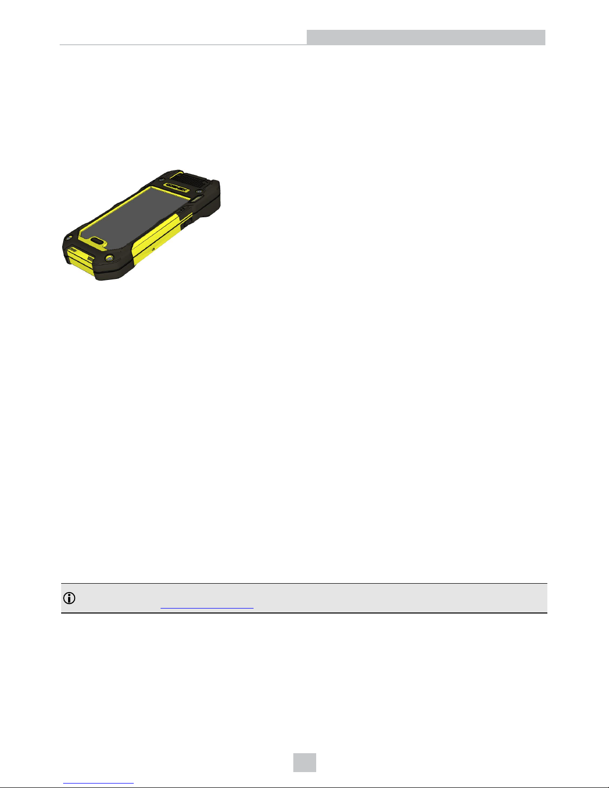
This section provides general information about the Cognex MX-1502 Vision-Enabled Mobile Terminal (henceforth
referred to as "MX-1502 reader"). You can also find information on the MX-1502 accessories and the physical layout of
the reader and the charging station in this section.
About MX-1502
The Cognex MX-1502 Vision-Enabled Mobile Terminal is a handheld ID mobile device supporting an integrated user
interface based on a consumer mobile device in an industrial grade housing. It features high-speed bar code reading
performance in a modular, rugged design that supports a variety of 3rd party mobile devices. The MX-1502 reader
provides the industry’s most advanced technology for reading 1-D and 2-D codes. The MX-1502X also reads
challenging 2-D DPM codes. It is designed to withstand heavy use in industrial settings and the unique modular design
allows you to stay current with mobile communications technology and easily replace or upgrade components without
the need for a service plan. The enhanced interface allows you to write and implement your own application according to
your work environment’s needs.
The MX-1502 reader offers the following features:
l LED aimer and illumination
l Long and extended range scanning
l No external connectors
l Vibro in the grip that ensures adequate feedback even in loud environments
The MX-1502 Kit includes the following:
l MX-1502 reader
l Battery
l Hand strap
Note: An appropriate mobile device is necessary to work with the MX-1502 reader. For the currently supported
mobile devices, see http://www.cognex.com
5
Getting Started
Page 6
MX-1502 Accessories
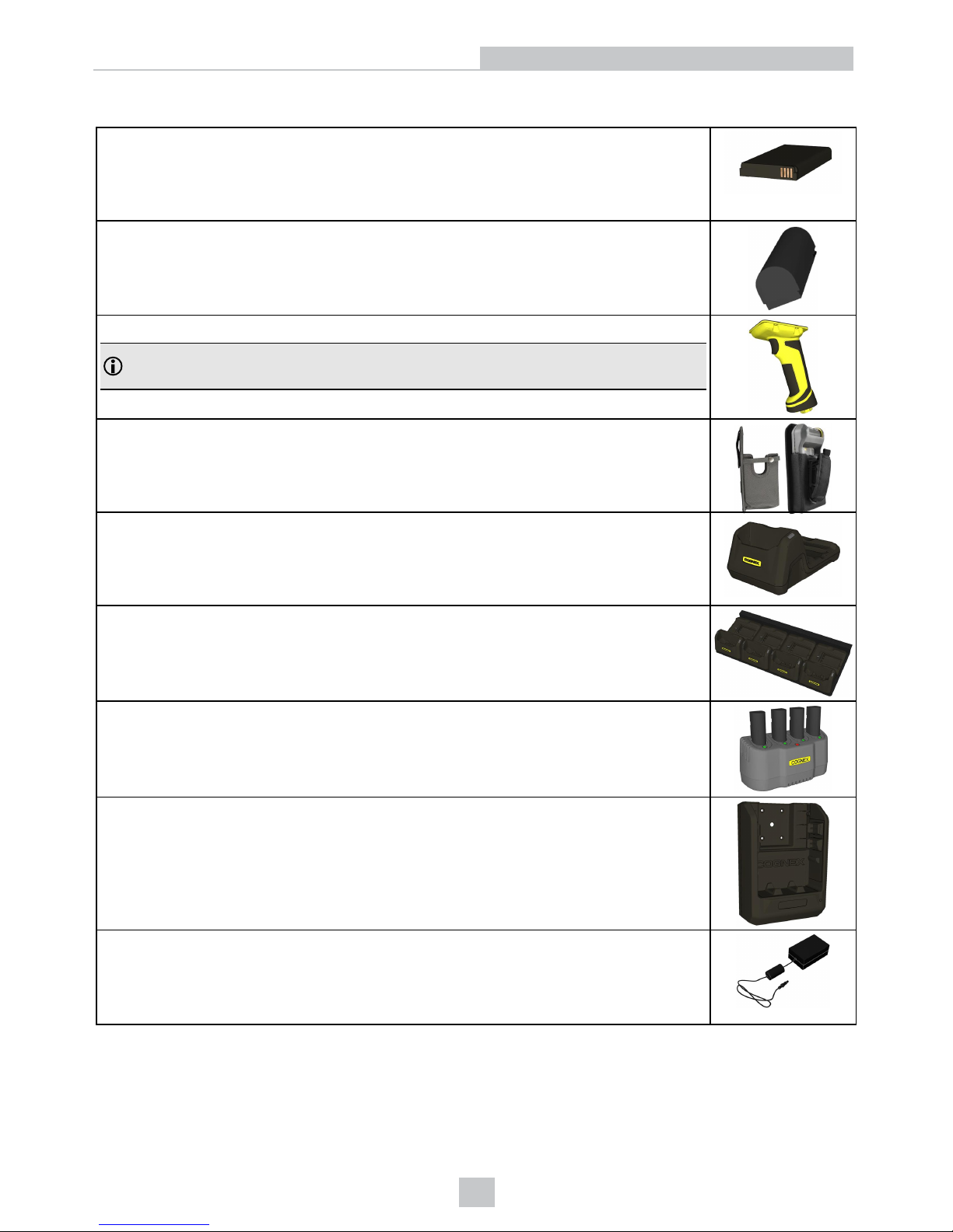
Battery for reader (DMA-MTBATTERY-01)
Battery for pistol grip accessory (3070 mAh, DMA-HHBATTERY-01)
Pistol grip (DMA-GRIP-01)
Note: The grip features its own trigger button and an additional battery which can be
charged via the charging station.
Belt holster (DMA-HOLSTER-01 and DMA-HOLSTER-02)
Wireless charging station (DMA-MTBASE-xx*)
Multi-device charger (DMA-MTBASE4-US, DMA-MTBASE4-EU, DMA-MTBASE4BKT-US, DMAMTBASE4BKT-EU)
Multi-battery charger (DMA-MBC-xx)
Wireless car charger (DMA-VMCHARGER-00)
Power supply for charging station 24V/18W (DMA-24VPWR-xx*)
6
Getting Started
Page 7
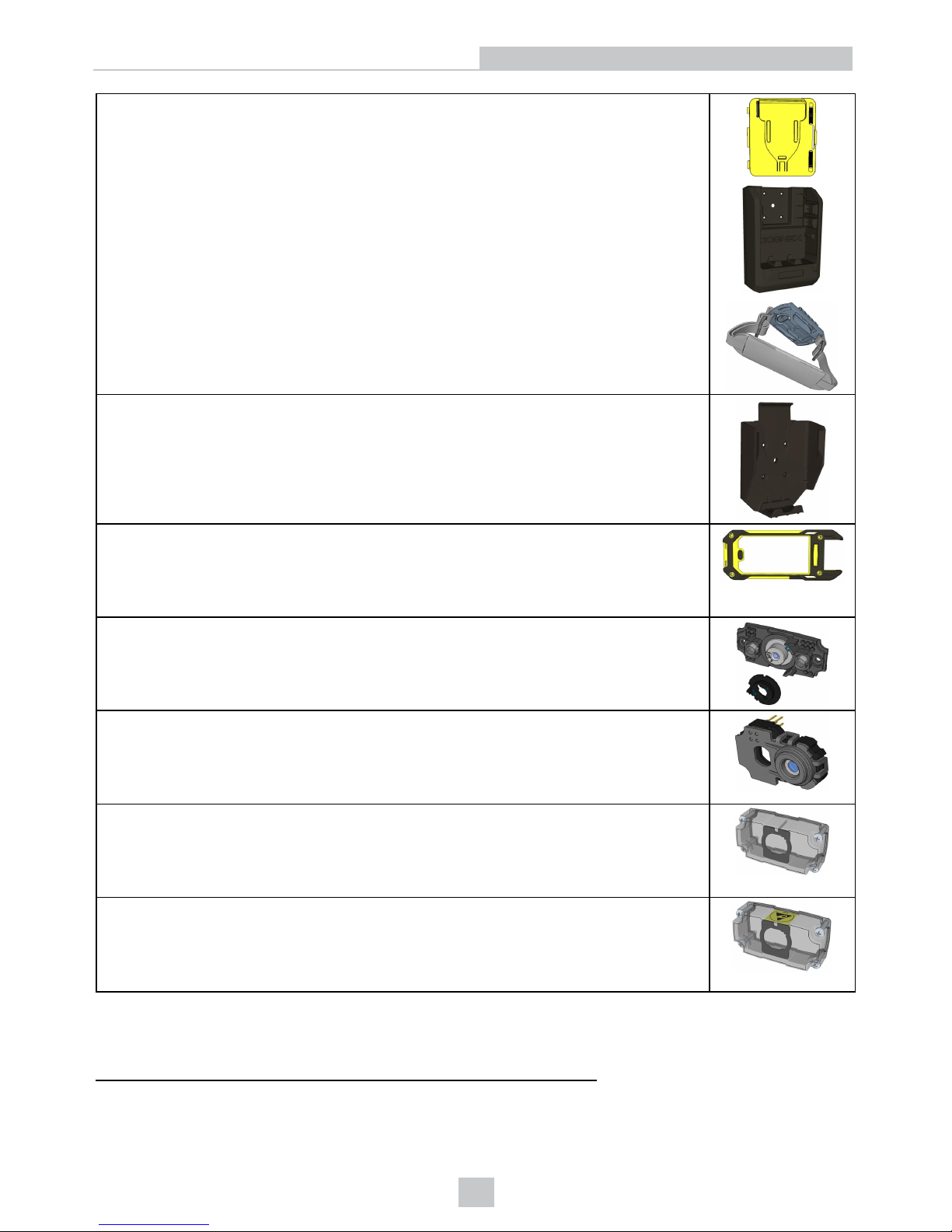
USB Type-C battery charger kits:
l DMA-MXUSB-01: USB Type-C Battery Cover (DMA-MXUSB-00) + USB Type-C 3Amp
Car Charger (DMA-MXUSB-CHARGER)
l DMA-MXUSB-02: USB Type-C Battery Cover (DMA-MXUSB-00) + Handstrap (DMA-
MXSTRAP-00)
l DMA-MXUSB-03: USB Type-C Battery Cover (DMA-MXUSB-00) + USB Type-C 3Amp
Car Charger (DMA-MXUSB-CHARGER) + Handstrap (DMA-MXSTRAP-00)
Passive car holder (DMA-VMHOLDER-00)
1
Top Cover (DMA-COVERKIT-S6, DMA-COVERKIT-S7)
6.2 mm lens kit (DM150-LENS-62)
Liquid Lens Module (LLM) to be used with 6.2 mm lens or 16 mm lens (DMA-LLM-150-260)
Clear lens cover (DM150-CVR-CLR)
Clear lens cover,ESD safe (DM150-CVR-ESD)
1
Using or storing the device outside of the recommended temperature r anges may damage or reduce the battery’slifespan. Leaving the MX
Series Mobile Terminal with a mobile device in direct sunlight for an extended amount of time can raise the temperature above the
recommended limit.
7
Getting Started
Page 8
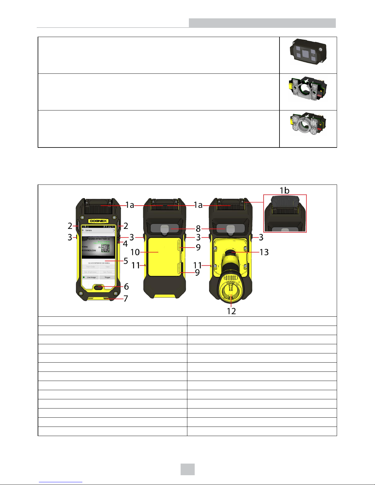
Polarized front cover (DM260-LENS-62CVR-F)
Standard illumination (DM150-LED-RED)
White LED illumination (DM150-LED-WHT)
Blue LED illumination (DM150-LED-BLU)
High Powered red LED illumination (DM260-LED-RED-HP)
* xx can be US or EU
MX-1502 Layout
1a/1b 1a: Standard front cover / 1b: Extended front cover
2 Indicator LEDs
3 Side trigger buttons
4 Power button
5 Touch screen
6 Home button
7 Speaker vents
8 Recessed area for mobile camera
9 Slider to lock battery cover
10 Battery cover
11 Lanyard hook
12 End cap of pistol grip*
13 Trigger button on the pistol grip*
8
Getting Started
Page 9

*Pistol grip is optional
9
Getting Started
Page 10
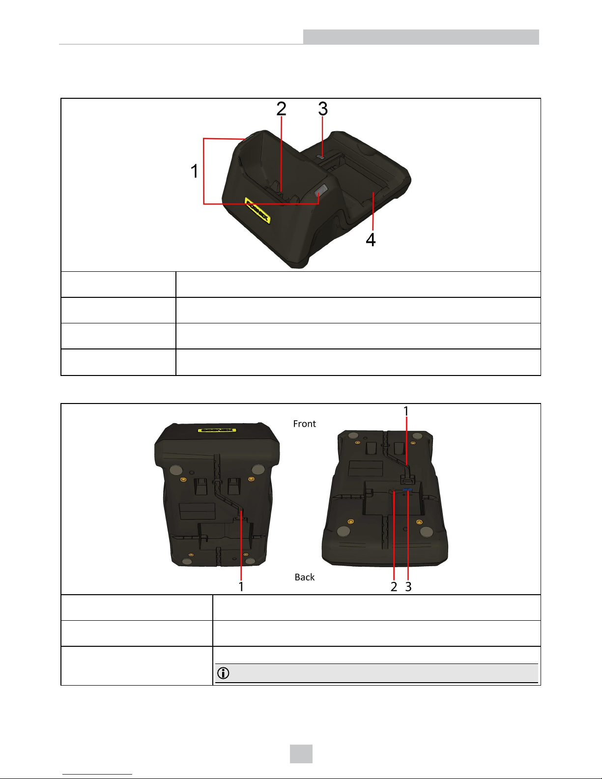
Layout of the Charging Station
Top view:
1 Charging station power LEDs (red light: inactive status - there is no device in the charger
bay; green light: charging is active)
2 Device charger bay
3 Battery charger LED (red light: active charging state; green light: charging is complete)
4 Spare battery charger bay
Bottom view:
1 Cable guide
2 Power plug (24 V, jack)
3
Power plug (24 V, terminal block)
Note: Supply power by using only one of the connectors.
10
Getting Started
Page 11
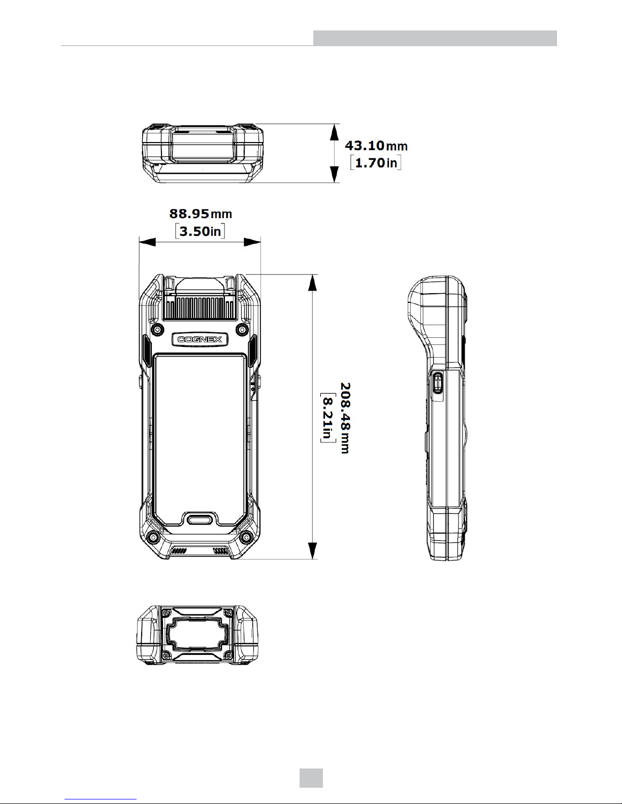
Dimensional Drawings
MX-1502 standard front cover model:
11
Getting Started
Page 12
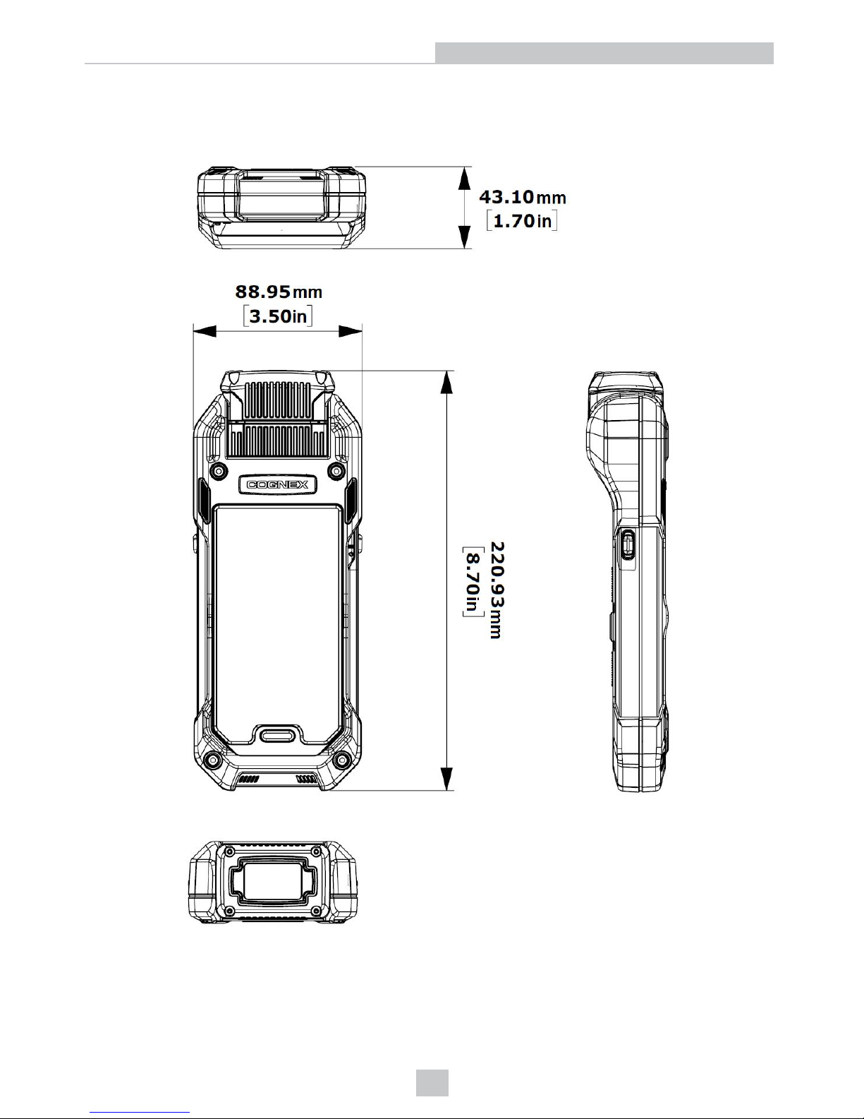
MX-1502 extended front cover model:
12
Getting Started
Page 13
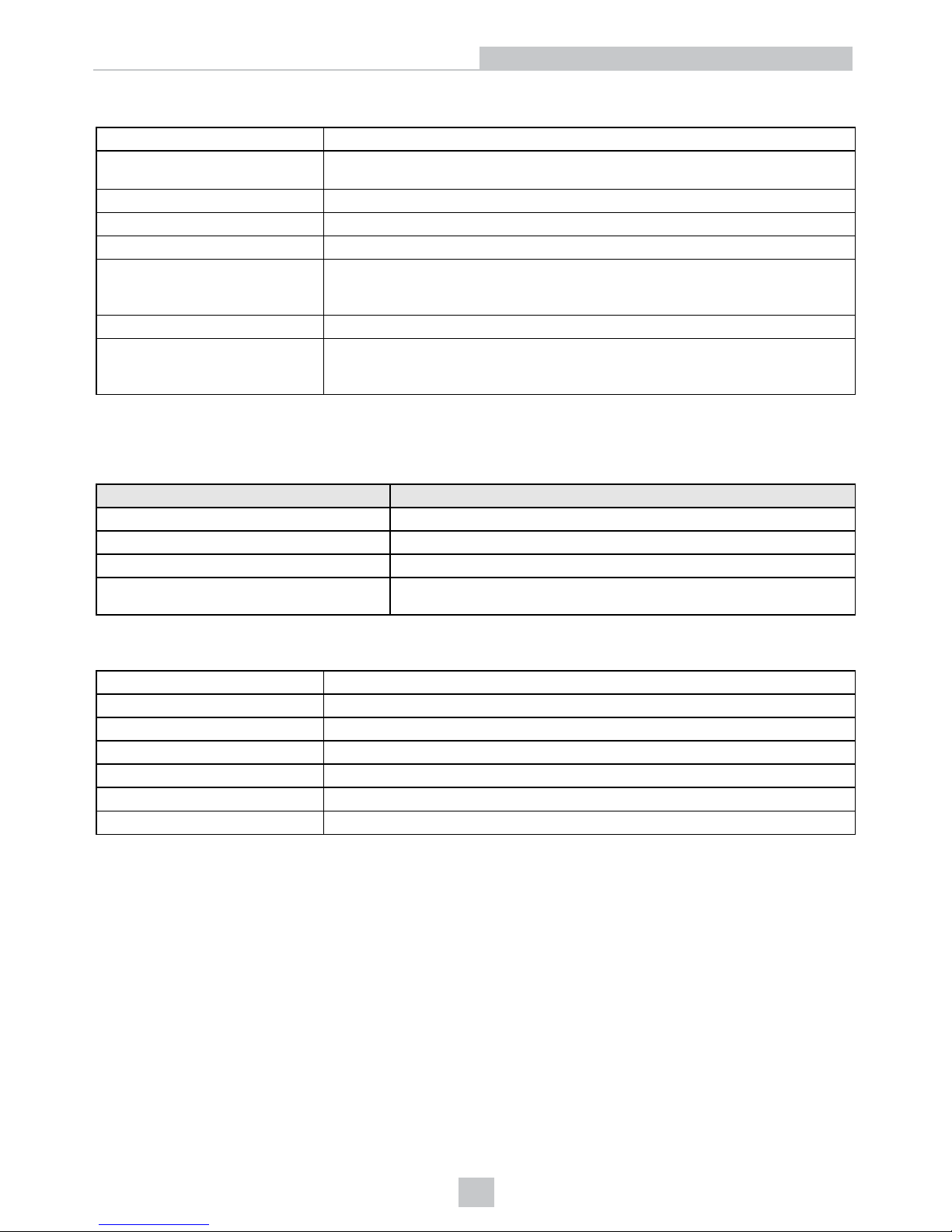
MX-1502 Specifications
Weight
499g (664g with pistol grip)
Charging Temperature
Operating Temperature
0ºC — +35ºC (+32ºF — +95ºF)
0ºC — +40ºC (+32ºF — +104ºF)
Storage Temperature -10ºC — +60ºC (
+10
ºF — +140ºF)
Maximum Humidity < 95% (non-condensing)
Environmental IP65
Codes
1-D
: UPC/EAN/JAN, Codabar, Interleaved 2 of 5, Code 39, Code 128, Code 93,
Pharmacode, GS1 DataBar, PDF417, Micro PDF417
2-D
: Data Matrix, QR Code, and MicroQR Code, DotCode* and postal code*
Power Supply Requirements Battery power
Expected operating time for typical
scan batches (400 scan per hour)
with a fully charged battery
12 hours
* MX-1502X only
Imager Specifications
Specification MX-1502 Standard and Long Range Imager
Image Sensor 1/3 inch CMOS
Image Sensor Properties 4.8mm x 3.6mm (W x H), 3.75 µm square pixels
Image Resolution (Pixels) 1280 x 960 global shutter sensor
Lens Type
S-mount 6.2 mm F:7 (with optional standard liquid lens) without IR
blocking filter
Charging Station Specifications
Weight 380 g
Operating Temperature 0ºC — +40ºC (+32ºF — +104ºF)
Storage Temperature -40ºC — +60ºC (-40ºF — +140ºF)
Charging Temperature 0ºC — +35ºC (+32ºF — +95ºF)
Maximum Humidity 95% (non-condensing)
Environmental IP40
Power Supply Requirements 24 V, 13 W maximum LPS or NEC Class 2 power supply
13
Getting Started
Page 14
Setting up the MX-1502
This section provides information on how to assemble and how to set up your MX-1502 reader.
Assembling the MX-1502
The first step in preparing your MX-1502 is assembling the components of your MX-1502 Kit. The MX-1502 Kit contains
the following components:
l Base unit with battery
l Rubber insert
l USBcable to connect the Base unit to the mobile device
l Top cover
l 4 Allen screws(M3) + Allen key
l Wrist strap
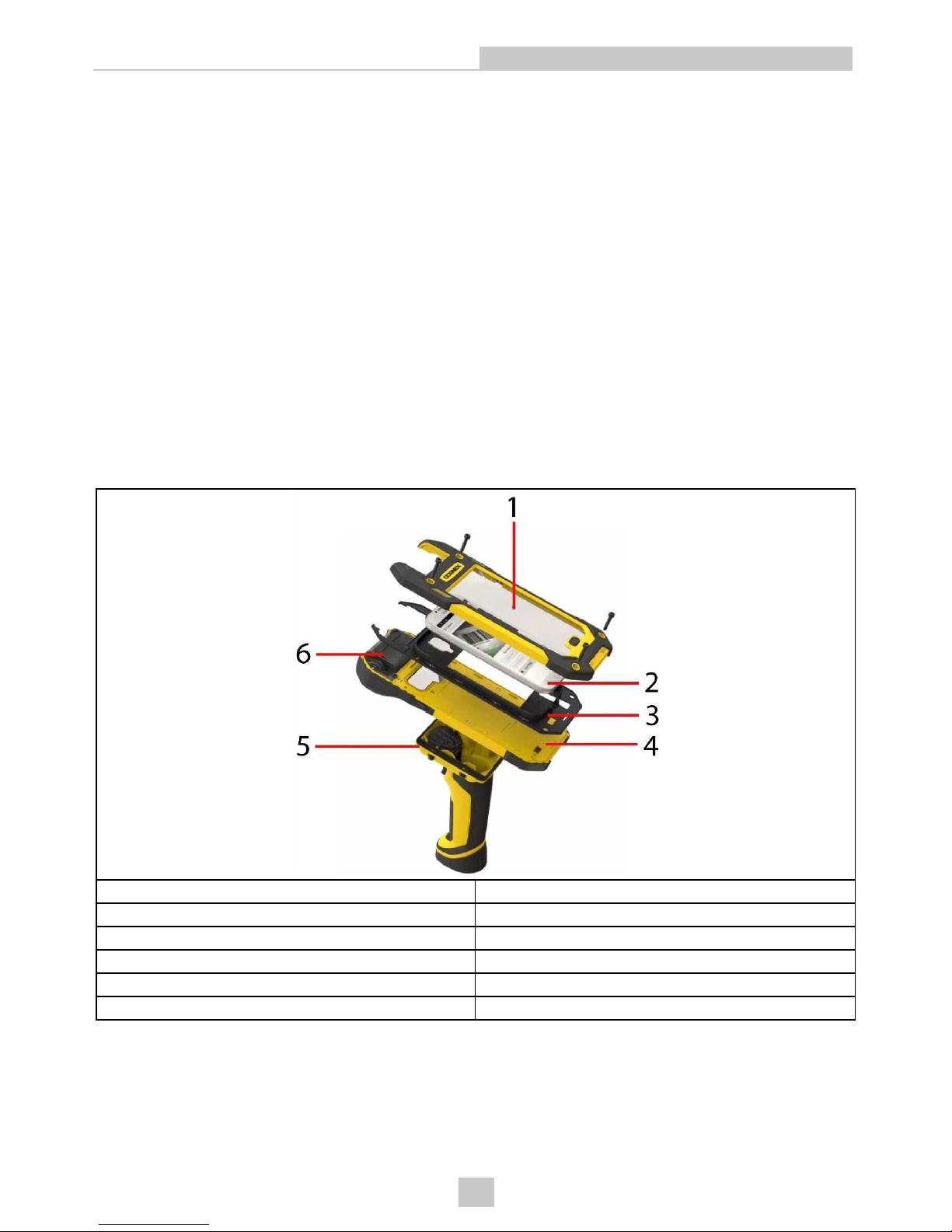
The following image shows the layering of the main kit components and the place of the mobile device among the layers.
1 Top cover
2 Mobile device
3 Rubber insert
4 Base unit
5 Pistol grip (optional)
6 Barcode reader
14
Setting up the MX-1502
Page 15
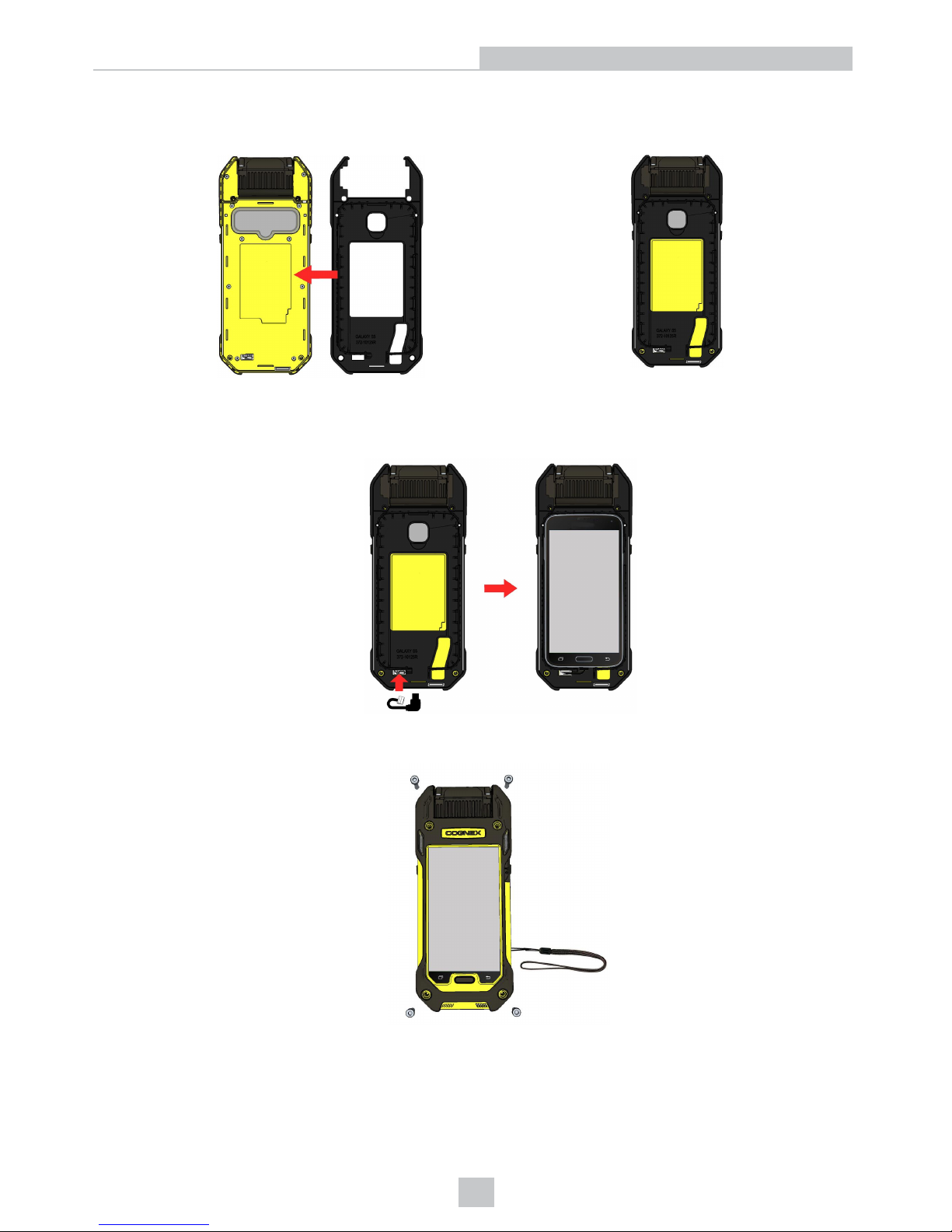
Perform the following steps to assemble the MX-1502 reader:
1. Carefully place the rubber insert on the base unit which is the lower part of the reader.
2. Take the provided USB cable and plug it into the base unit. Then take your phone and put it on the rubber
insert. Connect it to the base unit by the USB cable.
3. Fix the top cover by tightening the provided four Allen screws (recommended torque: 80 Ncm). Additionally, you
can attach the wrist strap to the reader by passing one of the screws through the loop on the wrist strap.
15
Setting up the MX-1502
Page 16
Assembling the Reader with the Pistol Grip
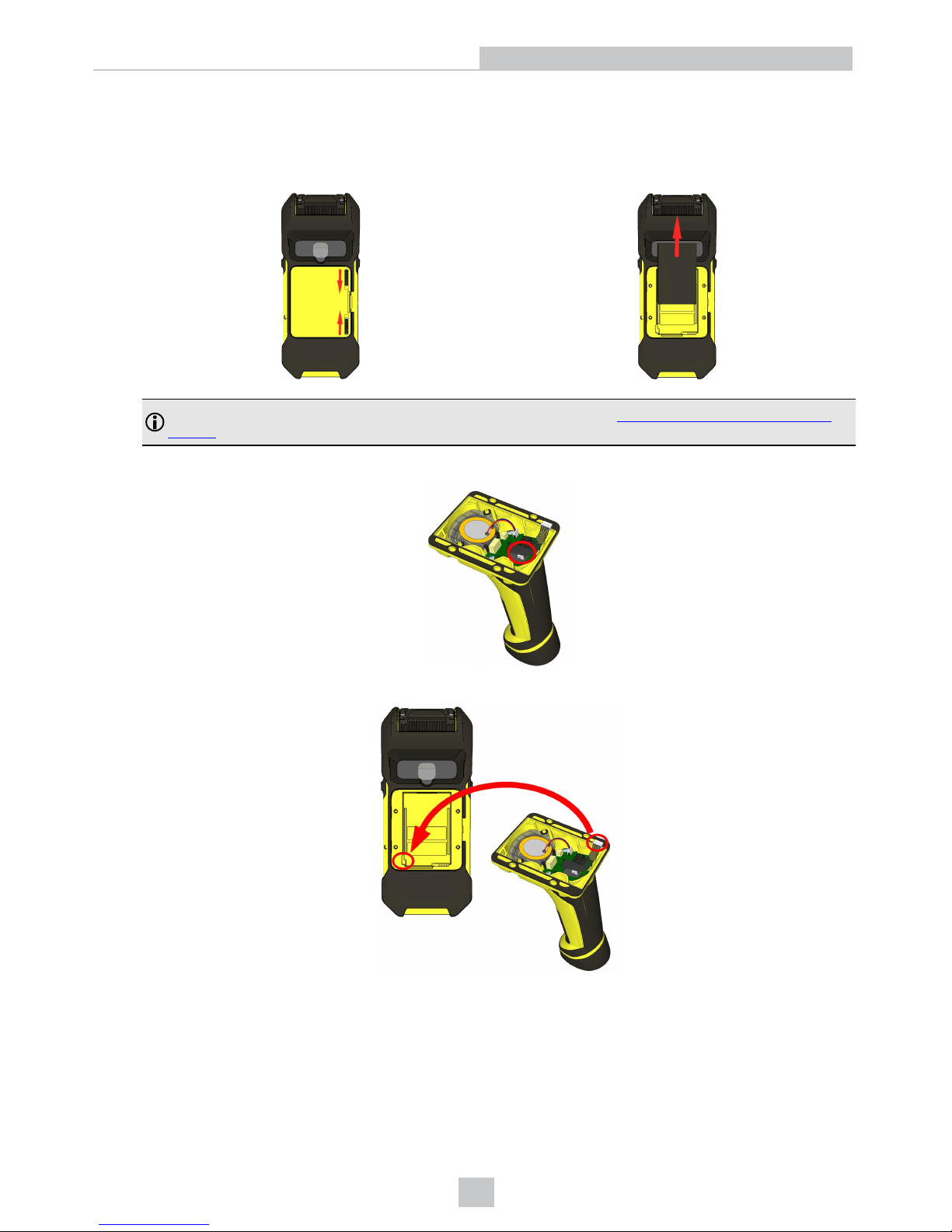
If you want to use your reader with a pistol grip, perform the following steps:
1. Open the back cover of the reader by unlocking the sliders and take out the battery.
Note: For more information about back cover locking and opening, see Changing Battery in the MX-1502
Reader).
2. Plug the pistol grip accessory cable into the grip accessory connector.
3. Insert the cable to the cable connector in the battery bay.
16
Setting up the MX-1502
Page 17
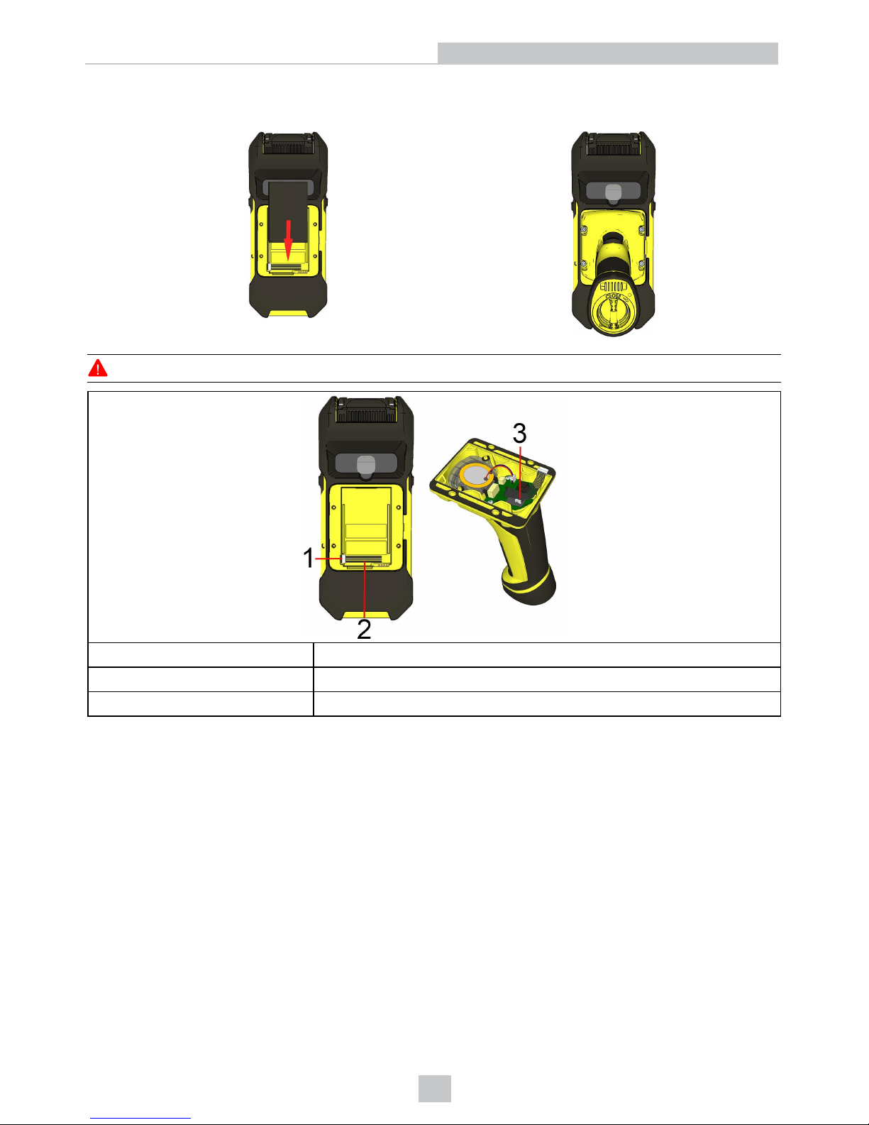
4. Insert the reader battery into the battery bay and then assemble the pistol grip and the reader by tightening the
four Allen screws.
WARNING: Do not insert the battery into the pistol grip during the assembly process.
1 Pistol grip accessory connector in the battery bay
2 Pistol grip accessory cable
3 Cable connector in the pistol grip
17
Setting up the MX-1502
Page 18
Charging
Charging an MX-1502 Using the Wireless Charging Station
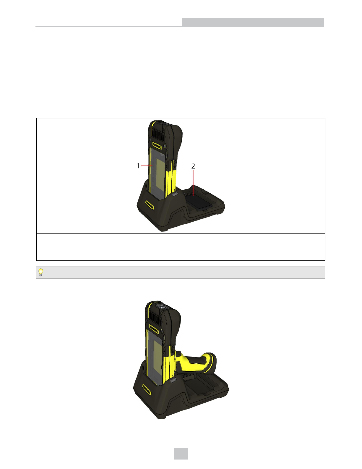
You can charge your MX-1502 reader using the wireless charging station. It has threaded inserts at the bottom to be
securely mountable on a surface. It allows to charge both the spare battery and the main unit.
The battery in the device and the spare battery in the charging station are fully charged in 4 hours.
The main battery and your mobile device are charged via the charging station. Additionally, the spare battery can be
charged in the charging station during the main battery charging.
1 Charging main battery and mobile device in the device charger bay
2 Charging spare battery in the spare battery charger bay
Tip: For optimum charging, do not power off your mobile device during the charging process.
The pistol grip battery can also be charged while charging the reader. In this case the main battery, the mobile device
and also the pistol grip battery are charged. Additionally, this charging does not prohibit charging the spare battery.
18
Setting up the MX-1502
Page 19
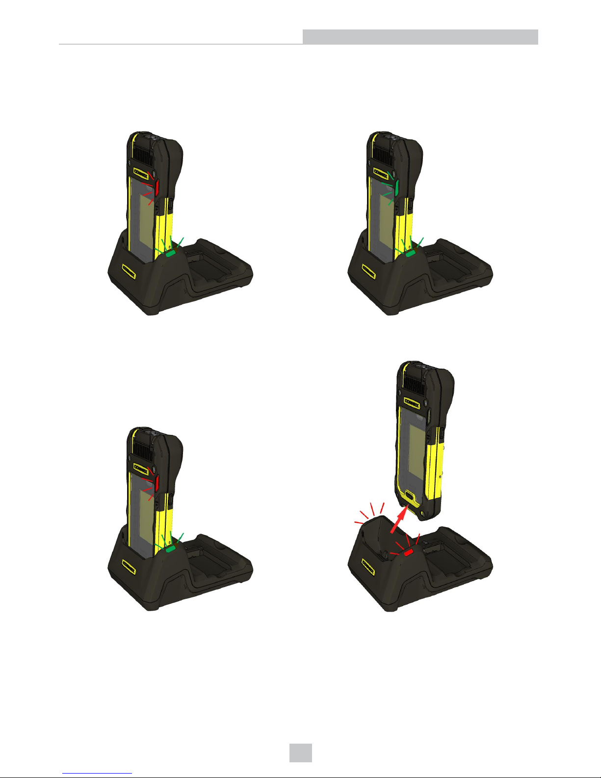
When you place your reader containing your mobile phone into the device bay of the charging station, the charging
station power LED becomes green and the indicator LED of the reader becomes red (1). It indicates that the charger is
active and the reader/mobile is charging. When the charging process is complete, the indicator of the reader LED turns
green (2).
1) 2)
When the wireless reader is removed from the device bay, the charging station power led becomes red. It indicates that
the charger is inactive.
To charge the spare battery, you need to insert it to the battery charging bay of the charging station. Make sure that the
battery properly fits the battery bay.
19
Setting up the MX-1502
Page 20
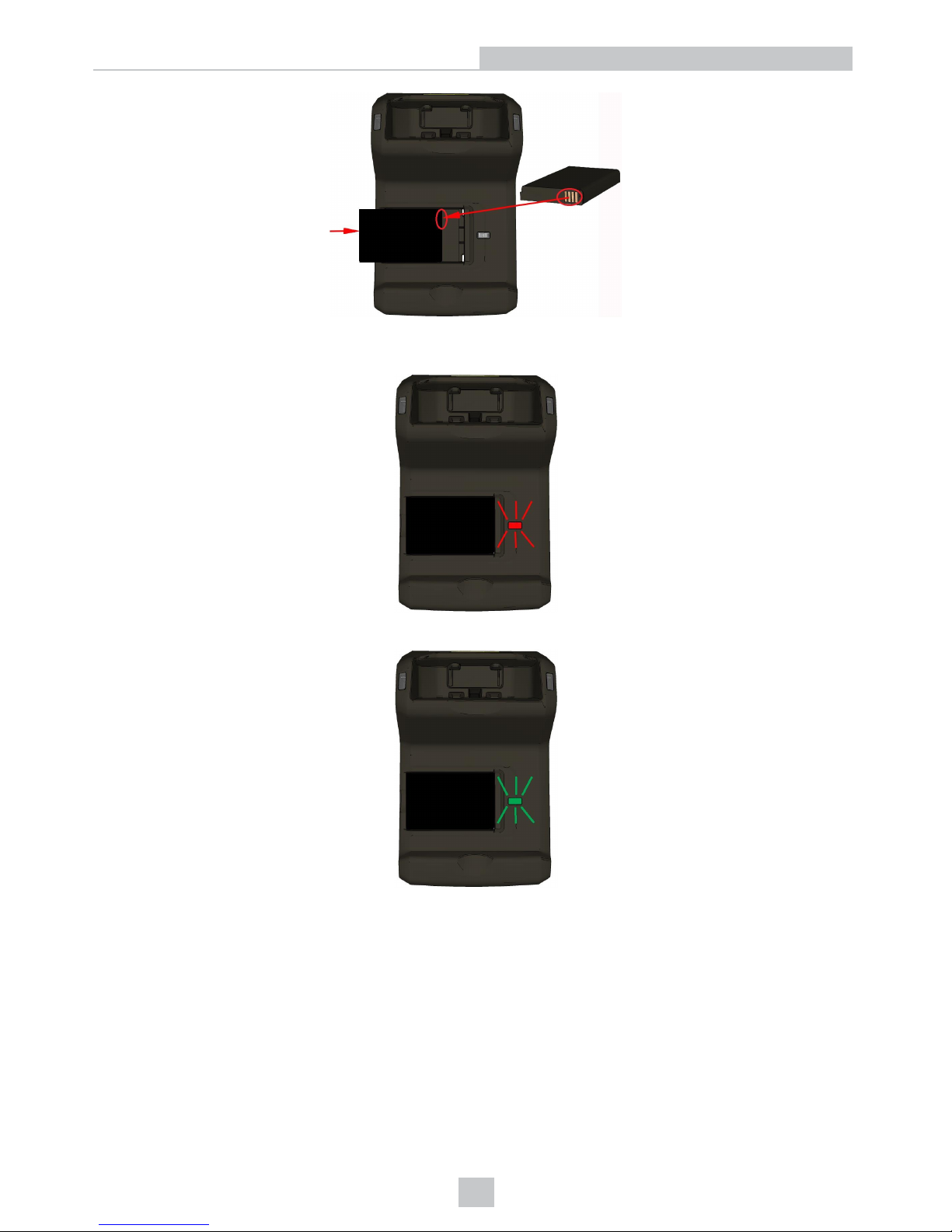
Once you put spare battery into the battery bay, the battery charger led light turns to red (the flashing red light indicates
an error).
When the charging is finished, the led light turns green.
20
Setting up the MX-1502
Page 21
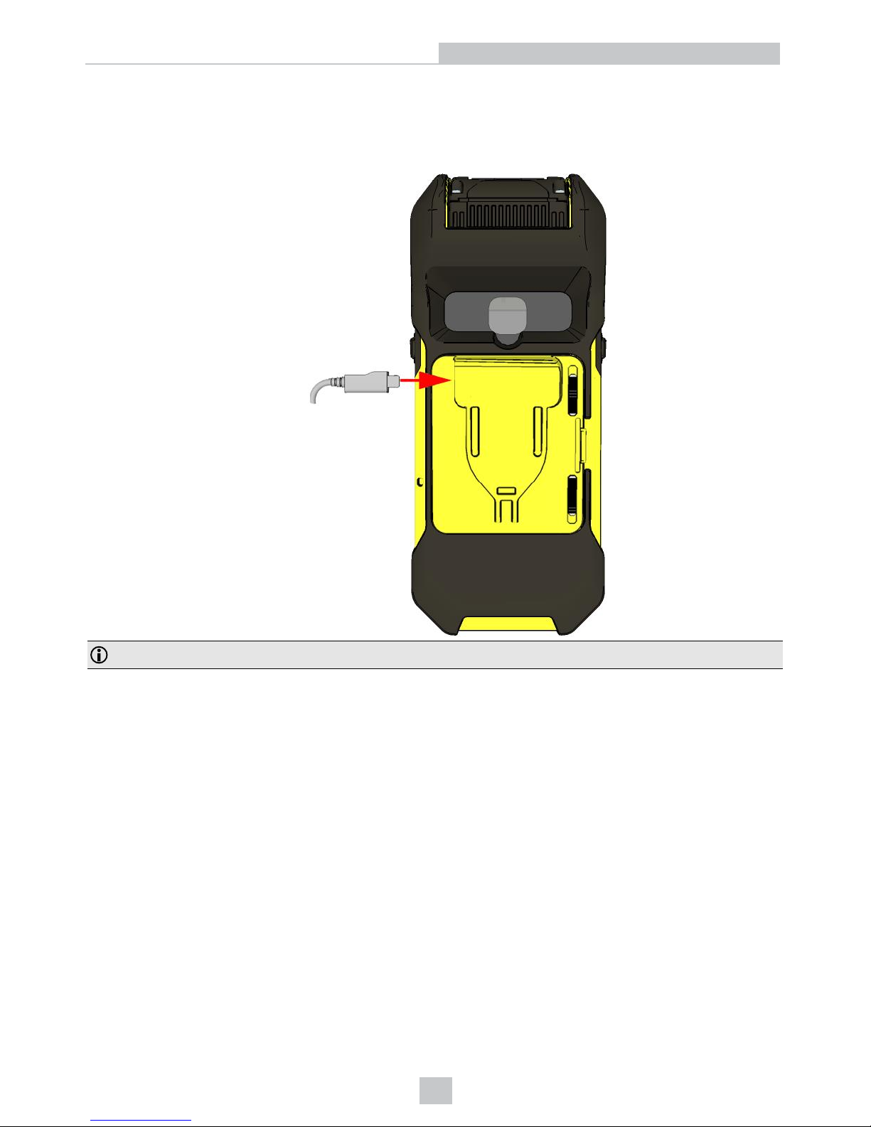
USB Type-C Charging
You can also charge your MX-1502 reader using USB if you use a USB Type-C battery cover.
1. Insert a 5V/3A Type-C USB cable into the slot in the battery cover and the reader starts charging.
Note: Both the cable and the power supply must be compatible with 5V/3A.
21
Setting up the MX-1502
Page 22
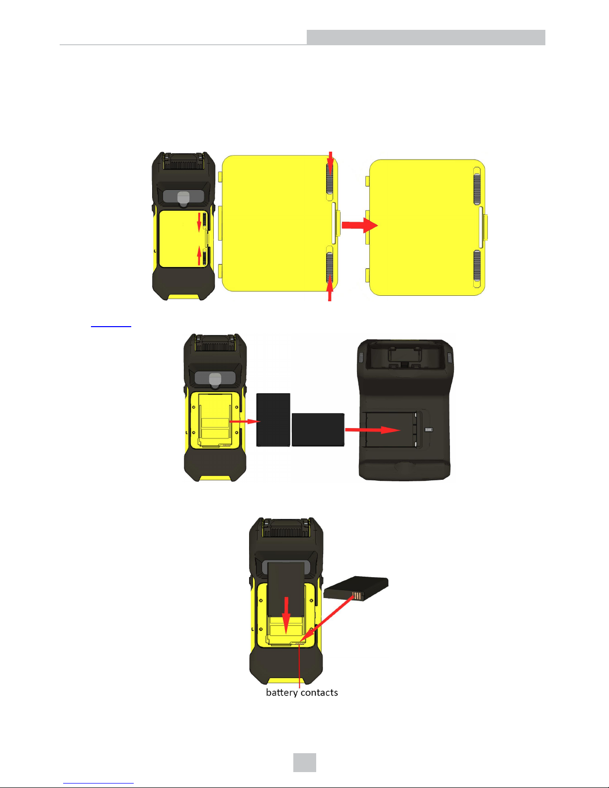
Changing Battery in the MX-1502 Reader
The MX-1502 reader contains a battery (lithium polymer battery, capacity: 3000 mAh) which you can charge by putting it
into the spare battery charging bay of the charging station.
To change the battery:
1. Open battery cover of your reader by unlocking the two cover sliders and pulling the cover side.
2. Take out the battery and charge it using the charging station. (For more information on charging the batteries, see
Charging.)
3. Put a new battery into the battery bay of your reader or wait until the charging process of the discharged battery is
finished. Make sure that the battery is properly installed in the battery bay.
22
Setting up the MX-1502
Page 23
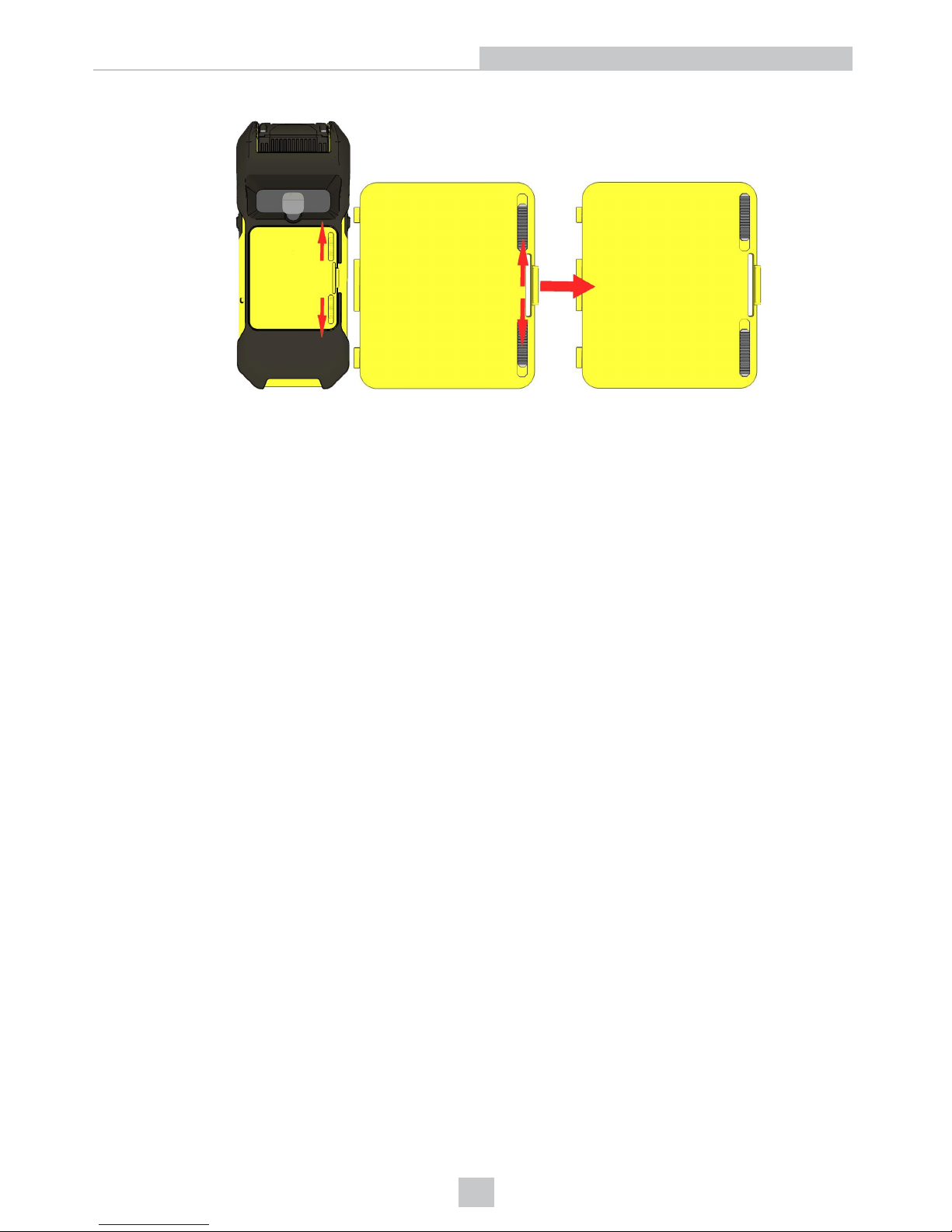
4. Close the battery bay by the locking the cover sliders.
23
Setting up the MX-1502
Page 24
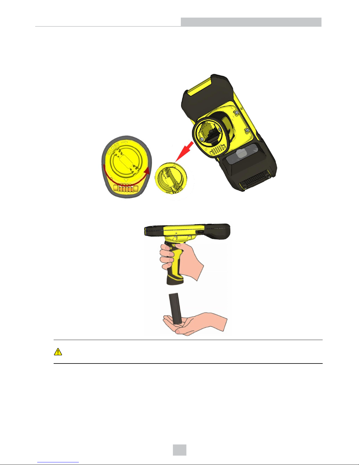
Changing Battery in the Pistol Grip
To change the battery in the pistol grip, perform the following steps:
1. Twist the reader’s end cap, and take it off.
2. Hold the reader in an upright position and the battery will slide out of the handle. You may need to shake the
reader slightly.
CAUTION: The battery used in these devices may present a risk of fire or chemical burn if mistreated. Do
not disassemble, heat above 60 ºC (140 ºF), or incinerate. Replace battery with Cognex DMA-HHBATTERY01 only. The use of another battery may present a risk of fire or explosion.
24
Setting up the MX-1502
Page 25
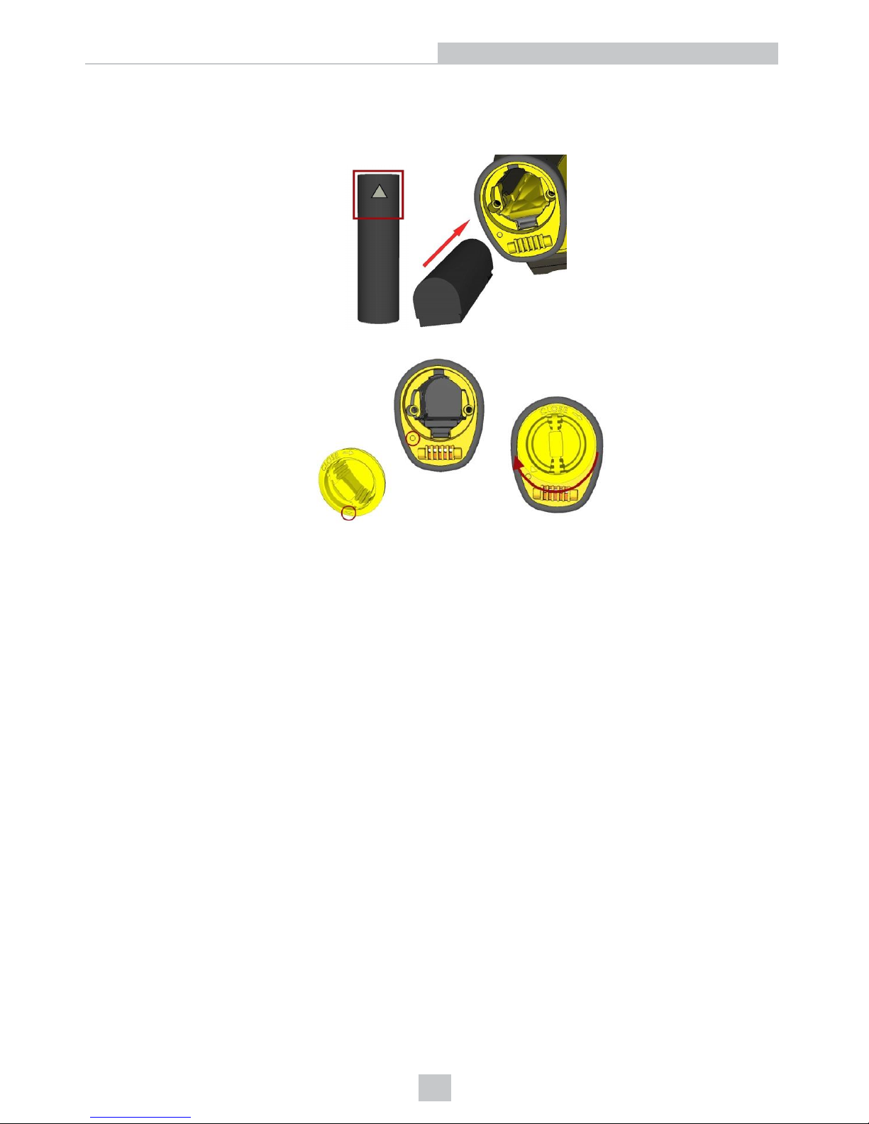
3. Put the replacement battery into the slot. The battery has a small triangle on one side. Make sure that you insert
the battery in a way that the triangle end goes into the slot first.
4. Put the end cap back on and twist it. Make sure that the triangle aligns with the circle when the cover is locked.
25
Setting up the MX-1502
Page 26
Reading Codes with your MX-1502
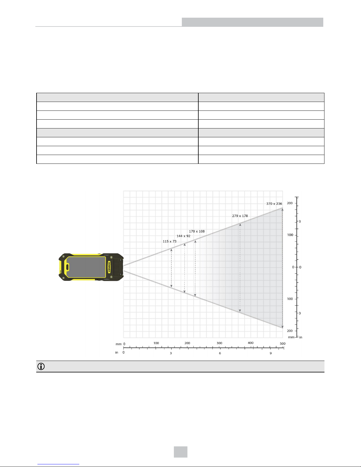
The following map shows the field of view of MX-1502 readers. Reading distance values are also provided for 2-D and
Code39 example code distances.
MX-1502-LR (Long Range) Readers with 6.2 mm Lens
Distances in mm 1D min. code
320 10 MIL
2000 50 MIL
4100 100 MIL
Distances in mm 2D min. code
170 10 MIL
900 50 MIL
1700 199 MIL
The following map shows the FoV of the MX-1502 readers with a 6.2 mm lens.
The FoV values are shown as follows:
Note: Due to tolerances, ranges can vary by +/- 5 mm for small codes to +/- a couple of centimeters for large codes.
26
Reading Codes with your MX-1502
Page 27
Cleaning/Maintenance
Cleaning the Reader Housing
To clean the outside of the reader housing, use a small amount of mild detergent cleaner or isopropyl alcohol on a
cleaning cloth. Do not pour the cleaner directly onto the reader housing.
CAUTION: Do not attempt to clean any DataMan product with harsh or corrosive solvents, including lye, methyl
ethyl ketone (MEK) or gasoline.
Cleaning the Reader Lens Cover
To remove dust from the lens cover, use a pressurized air duster. The air must be free of oil, moisture or other
contaminants that could remain on the lens cover. To clean the plastic window of the lens cover, use a small amount of
isopropyl alcohol on a cleaning cloth. Do not scratch the plastic window. Do not pour the alcohol directly on the plastic
window.
27
Cleaning/Maintenance
Page 28
Compliance Statements
The MX-1502 has Regulatory Model R00045 and meets or exceeds the requirements of all applicable standards
organizations for safe operation. However, as with any electrical equipment, the best way to ensure safe operation is to
operate them according to the agency guidelines that follow. Please read these guidelines carefully before using your
device.
The following specifications apply to the MX-1502 readers:
Regulator Specification
USA FCC Part 15, Subpart B Class A
Canada ICES-003, Class A
European Community
EN55032, Class A
EN55024
Japan
VCCI V-2/2015.04
Note: For the most up-to-date CE declaration and regulatory conformity information, please refer to the Cognex
online support site: http://www.cognex.com/Support.
Safety and Regulatory
European
Compliance
WARNING: This is a class A product. In a domestic environment this product may cause
radio interference in which case the user may be required to take adequate measures.
This equipment complies with the essential requirements of EU Directive 2014/30/EU.
Declarations are available from your local representative.
FCC Class A
Compliance
Statement
This equipment has been tested and found to comply with the limits for a Class A digital device,
pursuant to part 15 of the FCC Rules. These limits are designed to provide reasonable protection
against harmful interference when the equipment is operated in a commercial environment. This
equipment generates, uses, and can radiate radio frequency energy and, if not installed and used
in accordance with the instruction manual, may cause harmful interference to radio
communications. Operation of this equipment in a residential area is likely to cause harmful
interference in which case the user will be required to correct the interference at his own expense.
This device complies with part 15 of the FCC Rules. Operation is subject to the following two
conditions: (1) This device may not cause harmful interference, and
(2) this device must accept any interference received, including interference that may cause
undesired operation.
Canadian
Compliance
This Class A digital apparatus complies with Canadian ICES-003. Cet appareil numérique de la
classe A est conforme à la norme NMB-003 du Canada.
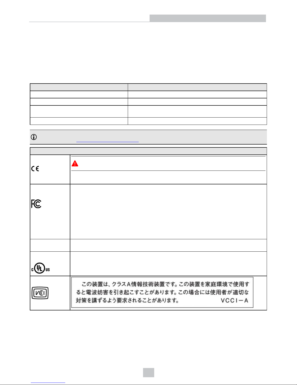
UL and cUL
Statement
UL 60950-1, CAN/CSA C22.2 No. 60950-1-07, IEC 60950
Japanese
Statement
For European Union Users
Cognex complies with Directive 2012/19/EU OF THE EUROPEAN PARLIAMENT AND OF THE COUNCIL of 4 July 2012
on waste electrical and electronic equipment (WEEE).
28
Compliance Statements
Page 29
This product has required the extraction and use of natural resources for its production. It may contain hazardous
substances that could impact health and the environment, if not properly disposed.
In order to avoid the dissemination of those substances in our environment and to diminish the pressure on the natural
resources, we encourage you to use the appropriate take-back systems for product disposal. Those systems will reuse or
recycle most of the materials of the product you are disposing in a sound way.
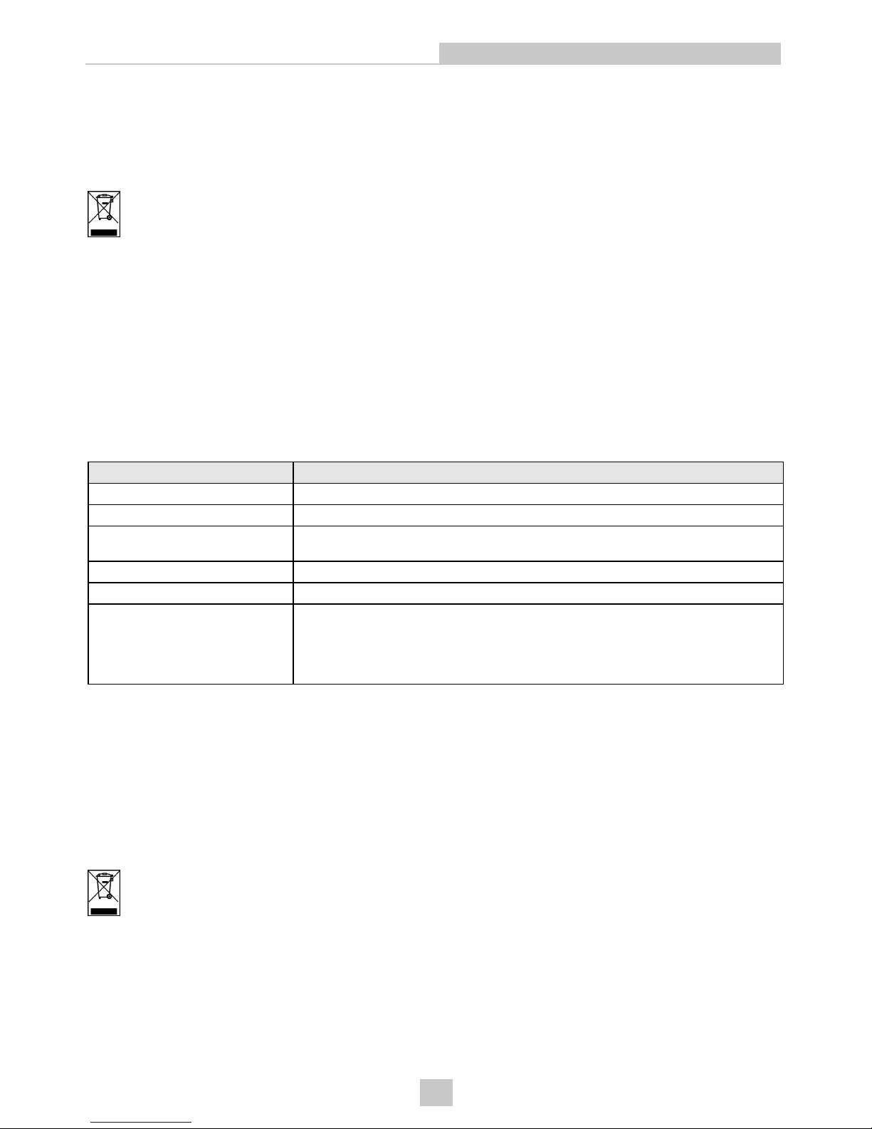
The crossed out wheeled bin symbol informs you that the product should not be disposed of along with municipal
waste and invites you to use the appropriate separate take-back systems for product disposal.
If you need more information on the collection, reuse, and recycling systems, please contact your local or regional waste
administration.
You may also contact your supplier for more information on the environmental performance of this product.
Compliance Statements: MX-1502 Charging Station
The MX-1502 Charging Station has Regulatory Model 1ABA and meets or exceeds the requirements of all applicable
standards organizations for safe operation. However, as with any electrical equipment, the best way to ensure safe
operation is to operate them according to the agency guidelines that follow. Please read these guidelines carefully
before using your device.
Regulator Specification
USA FCC 47 CFR Part 15, Subpart B Class A
Canada ICES-003, Class A
European Community
EN55032, Class A
EN55024
Australia AS/NZS 3548 Class A
Japan VCCI V-3/2015.04 Class A
Korea
IEC/CISPR 22
IEC/CISPR 24
KN22
KN24
Registration number: MSIP-REM-CGX-DMA-MT-BASE
For European Union Users
Cognex complies with Directive 2012/19/EU OF THE EUROPEAN PARLIAMENT AND OF THE COUNCIL of 4 July 2012
on waste electrical and electronic equipment (WEEE).
This product has required the extraction and use of natural resources for its production. It may contain hazardous
substances that could impact health and the environment, if not properly disposed.
In order to avoid the dissemination of those substances in our environment and to diminish the pressure on the natural
resources, we encourage you to use the appropriate take-back systems for product disposal. Those systems will reuse or
recycle most of the materials of the product you are disposing in a sound way.
The crossed out wheeled bin symbol informs you that the product should not be disposed of along with municipal
waste and invites you to use the appropriate separate take-back systems for product disposal.
If you need more information on the collection, reuse, and recycling systems, please contact your local or regional waste
administration.
You may also contact your supplier for more information on the environmental performance of this product.
29
Compliance Statements
Page 30
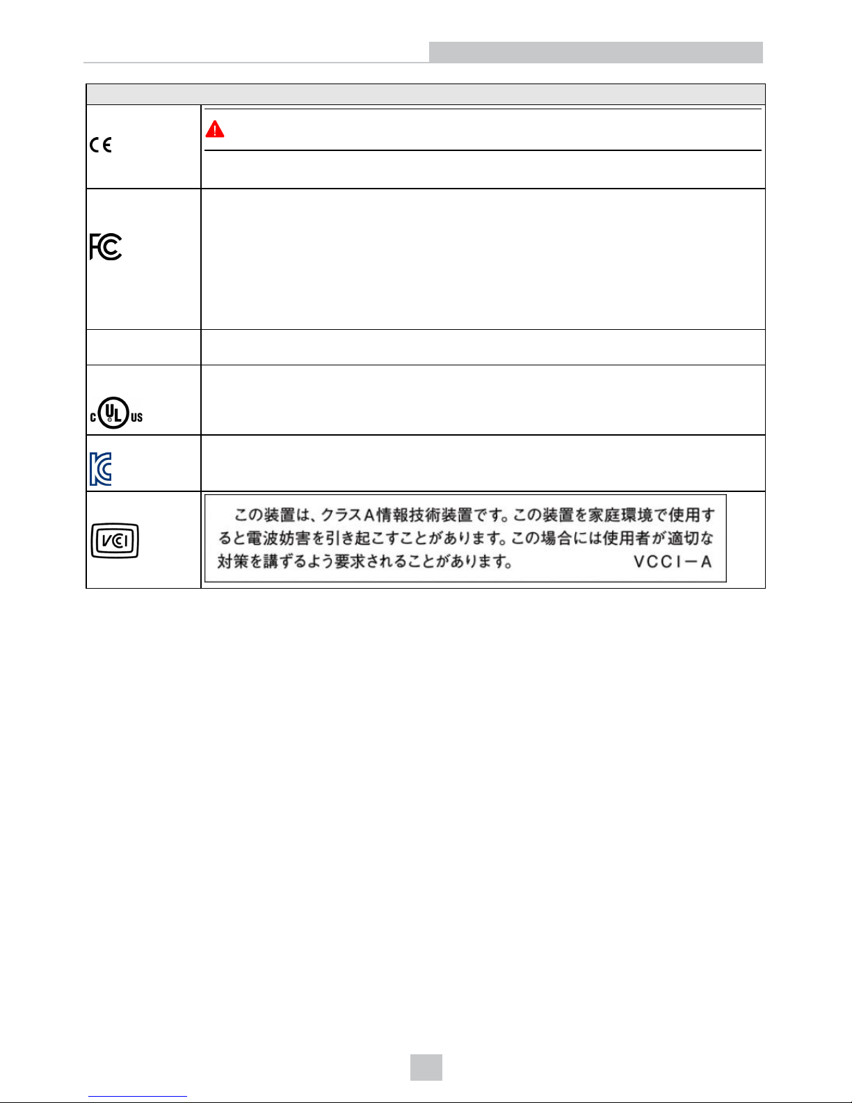
Safety and Regulatory
European
Compliance
WARNING: This is a Class A product. In a domestic environment this product may cause
radio interference in which case the user may be required to take adequate measures.
This equipment complies with the essential requirements of EU Directive 2014/30/EU.
Declarations are available from your local representative.
FCC Class A
Compliance
Statement
This device complies with Part 15 of the FCC Rules and with RSS-210 of Industry Canada.
Operation is subject to the following two conditions:
1. this device may not cause harmful interference, and
2. this device must accept any interference received, including interference that may cause
undesired operation.
Changes or modifications made to this equipment not expressly approved by Cognex may void the
FCC authorization to operate this equipment.
Canadian
Compliance
This Class A digital apparatus complies with Canadian ICES-003. Cet appareil numérique de la
classe A est conforme à la norme NMB-003 du Canada.
UL and cUL
Statement
UL 60950-1, CAN/CSA C22.2 No. 60950-1-07, IEC 60950
Korean Statement
Certificate number: MSIP-REM-CGX-DMA-MT-BASE
Japanese
Statement
30
Compliance Statements
Page 31

Precautions
Observe these precautions when installing the Cognex product, to reduce the risk of injury or equipment damage:
l To reduce the risk of damage or malfunction due to over-voltage, line noise, electrostatic discharge (ESD), power
surges, or other irregularities in the power supply, route all cables and wires away from high-voltage power
sources.
l Changes or modifications not expressly approved by the party responsible for regulatory compliance could void
the user’s authority to operate the equipment.
l Cable shielding can be degraded or cables can be damaged or wear out more quickly if a service loop or bend
radius is tighter than 10X the cable diameter. The bend radius must begin at least six inches from the connector.
l This device should be used in accordance with the instructions in this manual.
l All specifications are for reference purpose only and may be changed without notice.
31
Precautions
Page 32

Copyright © 2017
Cognex Corporation. All Rights Reserved.
 Loading...