

Cognex In-Sight 1ABD, In-Sight R00039, In-Sight 2000 Mini PoE, In-Sight 1ABF, In-Sight 2000-110 Reference Manual
...
®
In-Sight
2000 Series
Vision Sensor
Reference Guide
2019 May 06
Revision:5.7.3.29

Legal Notices
Legal Notices
The software described in this document is furnished under license, and may be used or copied only in accordance with
the terms of such license and with the inclusion of the copyright notice shown on this page. Neither the software, this
document, nor any copies thereof may be provided to, or otherwise made available to, anyone other than the licensee.
Title to, and ownership of, this software remains with Cognex Corporation or its licensor. Cognex Corporation assumes
no responsibility for the use or reliability of its software on equipment that is not supplied by Cognex Corporation.
Cognex Corporation makes no warranties, either express or implied, regarding the described software, its
merchantability, non-infringement or its fitness for any particular purpose.
The information in this document is subject to change without notice and should not be construed as a commitment by
Cognex Corporation. Cognex Corporation is not responsible for any errors that may be present in either this document or
the associated software.
Companies, names, and data used in examples herein are fictitious unless otherwise noted. No part of this document
may be reproduced or transmitted in any form or by any means, electronic or mechanical, for any purpose, nor
transferred to any other media or language without the written permission of Cognex Corporation.
Copyright © 2018 - 2019. Cognex Corporation. All Rights Reserved.
Portions of the hardware and software provided by Cognex may be covered by one or more U.S. and foreign patents, as
well as pending U.S. and foreign patents listed on the Cognex web site at: cognex.com/patents.
The following are registered trademarks of Cognex Corporation:
Cognex, 2DMAX, Advantage, AlignPlus, Assemblyplus, CheckitwithChecker, Checker, CognexVisionforIndustry,
CognexVSOC, CVL, DataMan, DisplayInspect, DVT, EasyBuilder, Hotbars, IDMax, In-Sight, LaserKiller, MVS-8000,
OmniView, PatFind, PatFlex, PatInspect, PatMax, PatQuick, SensorView, SmartView, SmartAdvisor, SmartLearn,
UltraLight, VisionSolutions, VisionPro, VisionView
The following are trademarks of Cognex Corporation:
The Cognex logo, 1DMax, 3D-Locate, 3DMax, BGAII, CheckPoint, CognexVSoC, CVC-1000, FFD, iLearn, In-Sight
(design insignia with cross-hairs), In-Sight2000, InspectEdge, Inspection Designer, MVS, NotchMax, OCRMax,
PatMaxRedLine, ProofRead, SmartSync, ProfilePlus, SmartDisplay, SmartSystem, SMD4, VisiFlex, Xpand
Portions copyright © Microsoft Corporation. All rights reserved.
Portions copyright © MadCap Software, Inc. All rights reserved.
Other product and company trademarks identified herein are the trademarks of their respective owners.
2

Regulations/Conformity
Regulations/Conformity
Note: For the most current CE declaration and regulatory conformity information, see the Cognex support site:
cognex.com/support.
Safety and Regulatory
Manufacturer
EU RoHS Compliant to the most recent applicable directive.
FCC FCC Part 15, Class A
Korea In-Sight 2000 Series Vision Sensor: Regulatory Model R00039: R-REM-CGX-R00039
Canadian
EMC
Compliance
UL and CUL
NRTL
Statement
Cognex Corporation
One Vision Drive
Natick, MA 01760 USA
In-Sight 2000 Series Vision Sensor: Regulatory Model R00039
In-Sight 2000 Mini Series Vision Sensor: Regulatory Model 1ABD
In-Sight 2000 Mini Series Vision Sensor (PoE models): Regulatory Model 1ABF
This is a class A product. In a domestic environment this product may cause radio interference in which
case the user may be required to take immediate measures. This equipment complies with the essential
requirements of the EU Directive 2014/30/EU. Declarations are available from your local representative.
This equipment has been tested and found to comply with the limits for a Class A digital device, pursuant
to part 15 of the FCC Rules. These limits are designed to provide reasonable protection against harmful
interference when the equipment is operated in a commercial environment. This equipment generates,
uses, and can radiate radio frequency energy and, if not installed and used in accordance with the
instruction manual, may cause harmful interference to radio communications. Operation of this
equipment in a residential area is likely to cause harmful interference in which case the user will be
required to correct the interference at his own expense.
In-Sight 2000 Mini Series Vision Sensor: Regulatory Model 1ABD: MSIP-REM-CGX-DM260
In-Sight 2000 Mini Series Vision Sensor (PoE models): Regulatory Model 1ABF: MSIP-REM-CGXDM260PoE
This device is certified for office use only and if used at home, there can be frequency interference
problems.
This Class A digital apparatus complies with Canadian ICES-003. Cet appareil numérique de la classe
A est conforme à la norme NMB-003 du Canada.
UL 60950-1, 2nd Edition, 2014-10-14
CAN/CSA C22.2 No. 60950-1-07, 2nd Edition, 2014-10
CB UL IEC/EN 60950-1. CB report available upon request.
3

Regulations/Conformity
China RoHS
Hazardous Substances 有害物 质
Part Name
部件名 称
Regulatory
Model R00039
Regulatory
Model 1ABD
Regulatory
Model 1ABF
This table is prepared in accordance with the provisions of SJ/T 11364.
这个标 签 是 根据SJ / T 11364 的 规 定 准备的。
O: Indicates that said hazardous substance contained in all of the homogeneous materials for this part is below the limit
requirement of GB / T26572 - 2011.
表示本 部 件 所有均质材 料 中 含 有的有害物 质 低 于GB / T26572 - 2011 的限量要求 。
X: Indicates that said hazardous substance contained in at least one of the homogeneous materials used for this part is
above the limit requirement of GB / T26572 - 2011.
表示用 于 本 部件的至少 一 种 均 质材料中所 含 的 危害物质超 过 GB / T26572 - 2011 的 限 制要求。
Lead (Pb)铅Mercury (Hg)汞Cadmium
(Cd)
镉
X O O O O O
Hexavalent
Chromium
(Cr (VI))
六价铬
Polybrominated
biphenyls (PBB)
多溴联 苯
Polybrominated
diphenyl ethers (PBDE)
多溴二 苯 醚
For European Community Users
Cognex complies with Directive 2012/19/EU OF THE EUROPEAN PARLIAMENT AND OF THE COUNCIL of 4 July 2012
on waste electrical and electronic equipment (WEEE).
This product has required the extraction and use of natural resources for its production. It may contain hazardous
substances that could impact health and the environment, if not properly disposed.
In order to avoid the dissemination of those substances in our environment and to diminish the pressure on the natural
resources, we encourage you to use the appropriate take-back systems for product disposal. Those systems will reuse or
recycle most of the materials of the product you are disposing in a sound way.
The crossed out wheeled bin symbol informs you that the product should not be disposed of along with municipal
waste and invites you to use the appropriate separate take-back systems for product disposal.
If you need more information on the collection, reuse, and recycling systems, please contact your local or regional waste
administration.
You may also contact your supplier for more information on the environmental performance of this product.
4

Precautions
Precautions
To reduce the risk of injury or equipment damage, observe the following precautions when you install the Cognex
product:
l This device requires the use of an LPS or NEC class 2 power supply. Any other voltage creates a risk of fire or
shock and can damage the components. Applicable national and local wiring standards and rules must be
followed.
l Route cables and wires away from high-current wiring or high-voltage power sources to reduce the risk of
damage or malfunction from the following causes: over-voltage, line noise, electrostatic discharge (ESD), power
surges, or other irregularities in the power supply.
l This product is intended for industrial use in automated manufacturing or similar applications.
l The safety of any system incorporating this product is the responsibility of the assembler of the system.
l Do not install Cognex products where they are exposed to environmental hazards such as excessive heat, dust,
moisture, humidity, impact, vibration, corrosive substances, flammable substances, or static electricity.
l Do not expose the image sensor to laser light. Image sensors can be damaged by direct, or reflected, laser light.
If your application requires laser light that might strike the image sensor, use a lens filter at the corresponding
laser wavelength. For suggestions, contact your local integrator or application engineer.
l This product does not contain user-serviceable parts. Do not make electrical or mechanical modifications to
product components. Unauthorized modifications can void your warranty.
l Include service loops with cable connections. Changes or modifications not expressly approved by the party
responsible for regulatory compliance could void the user’s authority to operate the equipment.
l Ensure that the cable bend radius begins at least six inches from the connector. Cable shielding can be
degraded or cables can be damaged or wear out faster if a service loop or bend radius is tighter than 10X the
cable diameter.
l This device is certified for office use only and if used at home, there can be frequency interference problems.
l This device should be used in accordance with the instructions in this manual.
l Applicable national and local wiring standards and rules must be followed.
l All specifications are for reference purposes only and can change without notice.
5

Symbols
The following symbols indicate safety precautions and supplemental information:
WARNING: This symbol indicates a hazard that could cause death, serious personal injury or electrical shock.
CAUTION: This symbol indicates a hazard that could result in property damage.
Note: This symbol indicates additional information about a subject.
Tip: This symbol indicates suggestions and shortcuts that might not otherwise be apparent.
Symbols
6

Table of Contents
Table of Contents
Legal Notices 2
Regulations/Conformity 3
China RoHS 4
For European Community Users 4
Precautions 5
Symbols 6
Table of Contents 7
Introduction 9
Support 9
Standard Components 9
Options and Accessories 10
In-Sight 2000 Vision Sensor Lenses, Lights, Filters and Covers 10
In-Sight 2000 Mini Vision Sensor Lights, Filters and Covers 11
Cables 12
PowerSupplies (Non-PoE Models Only) 12
Mounting Brackets 12
I/OModule 13
Replacement Kit 13
Connectors and Indicators 14
Installation 15
Install the In-Sight 2000 Vision Sensor 15
Mounting Configurations 15
Mount the Vision Sensor 17
Set the Focus Position (S-Mount/M12 Lens Configuration) 18
Replace the M12 Lens (S-Mount/M12 Lens Configuration) 19
Install the Lens Filter (S-Mount/M12 Lens Configuration) 21
Replace the LED Ring Light (S-Mount/M12 Lens Configuration) 23
Install the In-Sight 2000 Mini Vision Sensor 25
Mount the Vision Sensor 25
Mounting Configurations 26
Replace the LED Light 28
Install the Lens Filter 30
Working Distance and Field of View 32
In-Sight 2000 Vision Sensor (S-Mount/M12 Lens Configuration) 32
In-Sight 2000 Vision Sensor (Liquid Lens Configuration) 34
In-Sight 2000 Mini Vision Sensor 36
Connect the Ethernet Cable 38
Connect the Breakout Cable (Optional for PoE Models) 38
Connect the CIO-1400 I/O Expansion Module (Optional) 40
Specifications 42
In-Sight 2000 Vision Sensor Specifications 42
In-Sight 2000 Mini Vision Sensor Specifications 44
Acquisition Trigger 46
General-Purpose Input 47
7

Table of Contents
High-Speed Outputs 48
High-Speed Output Wiring 49
Breakout Cable Specifications 50
Ethernet Cable Specifications 51
I/O Module Cable Specifications 52
In-Sight 2000 Vision Sensor Dimensions 53
In-Sight 2000 Mini Vision Sensor Dimensions (With 6.2 mm Lens) 54
In-Sight 2000 Mini Vision Sensor Dimensions (With 16 mm Lens) 55
Cleaning/Maintenance 56
Clean the Vision Sensor Housing 56
Clean the Vision Sensor Image Sensor Window 56
Clean the Vision Sensor Lens Cover 56
8

Introduction
Introduction
The In-Sight®2000 is a compact, network-ready, stand-alone machine vision sensor used for automated inspection and
measurement applications on the factory floor. All models can be easily programmed remotely over a network using an
intuitive user interface.
Support
Resources available to assist you in using the vision sensor:
l The In-Sight
l The In-Sight online support site: cognex.com/support/insight.
Standard Components
Note:
l Cables are sold separately.
l If a standard component is missing or damaged, immediately contact your Cognex Authorized Service
Provider (ASP) or Cognex Technical Support.
®
Explorer Help and EasyBuilder Help files, provided with In-Sight Explorer software.
Product Components
In-Sight 2000
Vision Sensor
In-Sight 2000 Mini
Vision Sensor
1. Optics module, featuring high brightness LED ring light and SMount/M12 lens, or liquid lens with auto-focus capability
2. Main module, including sensor and CPU
3. I/O connector module
1. Optics module, featuring LED light and liquid lens with autofocus capability
2. Main module, including sensor and CPU
3. I/O connector module
9

Options and Accessories
In-Sight 2000 Vision Sensor Lenses, Lights, Filters and Covers
Lens Options
Lens, M12, 3.6 mm (LM12-03-01)
Lens, M12, 6 mm (LM12-06-01)
Lens, M12, 8 mm (LM12-08-01)
Lens, M12, 12 mm (LM12-12-01)
Lens, M12, 16 mm (LM12-16-01)
Lens, M12, 25 mm (LM12-25-01)
Lens Spacer, M12, 16 mm (LM12-SPACER-16-0)
Lens Spacer, M12, 25 mm (LM12-SPACER-25-01)
Lights
High Brightness Red LED Ring Light (IFS-2000-HBRING-RD)
High Brightness White LED Ring Light (IFS-2000-HBRING-WH)
High Brightness Blue LED Ring Light (IFS-2000-HBRING-BL)
High Brightness Near IR LED Ring Light (IFS-2000-HBRING-IR)
Introduction
Filters and Covers
Red Bandpass Filter, 635 nm (IMRF-2000-BP635)
Blue Bandpass Filter, 470 nm (IMBF-2000-BP470)
IR Bandpass Filter, 850 nm (IMIF-2000-BP850)
Polarizer Cover (IMPF-2000-POLAR)
10

Replacement Cover (IFS-2000-HBRING-CV)
Clear Cover (IFS-2000-HBRING-CC)
In-Sight 2000 Mini Vision Sensor Lights, Filters and Covers
Lights
Red LED Light for 6.2 mm Lens (DM150-LED-RED)
White LED Light for 6.2 mm Lens (DM150-LED-WHT)
Blue LED Light for 6.2 mm Lens (DM150-LED-BLU)
High Powered Red LED Light for 16 mm Lens (DM260-LED-RED-HP)
Introduction
High Powered White LED Light for 16 mm Lens (DM260-LED-WHT-HP)
Filters and Covers
Blue Bandpass Filter (DM150-BP470)
Red Bandpass Filter (DM150-BP635)
Clear Cover for 6.2 mm Lens (DM150-CVR-CLR)
Clear Cover for 6.2 mm Lens,ESD Safe (DM150-CVR-ESD)
Polarized Cover for 6.2 mm Lens (DM260-LENS-62CVR-F)
Extended Cover for 16 mm Lens, Un-polarized (DM260-LENS-16CVR)
Extended Cover for 16 mm Lens, Half-polarized (DM260-LENS-16CVR-P)
Extended Cover for 16 mm Lens, Fully Polarized (DM260-LENS-16CVR-F)
11
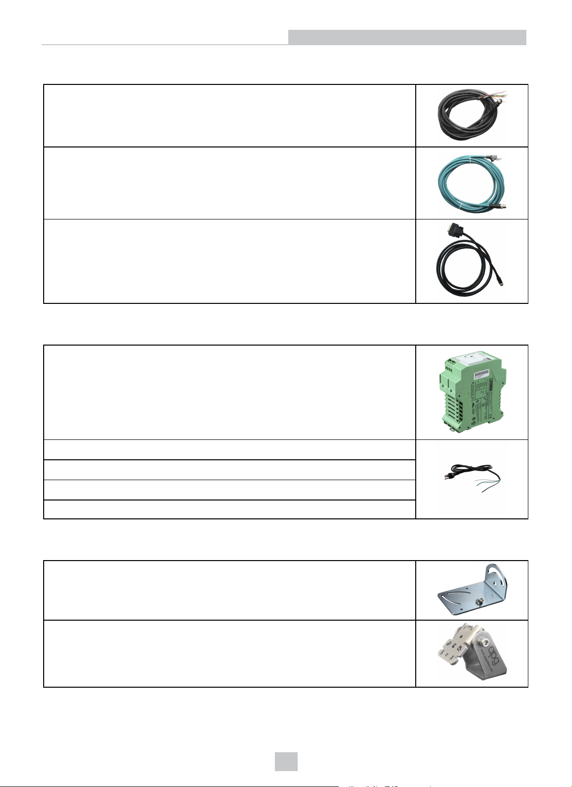
Cables
Breakout Cable, M12-12 to Flying Lead (CCB-PWRIO-xx) (xx specifies length: 5m, 10m,
15m)
Ethernet X-coded M12-8 to RJ-45 Cable (CCB-84901-2001-xx) (xx specifies length: 2m,
5m, 10m, 15m, 30m)
I/O Module Cable M12-12 to DB15 (CCB-PWRIO-MOD-xx) (xx specifies length: 2m, 5m)
Introduction
PowerSupplies (Non-PoE Models Only)
Cognex 24VDC Power Supply (ACC-24I)
North America Power Cord (CBLI-24VDUS)
Japan Power Cord (CBLI-24VDJP)
United Kingdom Power Cord (CBLI-24VDUK )
Europe Power Cord (CBLI-24VDEU)
Mounting Brackets
Universal Mounting Bracket (DM100-UBRK-000)
Pivot Mounting Bracket (DM100-PIVOTM-00)
12

Flat Surface Mounting Plate Adapter (BKT-2000-ADAPT-00)
I/OModule
Introduction
In-Sight CIO-1400 I/O Expansion Module (CIO-1400)
Replacement Kit
Screws, Washers, and Caps Kit (IS2000-CAPS-KIT)
1
1
The CIO-1400 I/O expansion module supports In-Sight 2000 series vision sensors with firmware version 5.3.0 and higher.
13

Connectors and Indicators
Connector Function
Ethernet
connector (left)
Power, I/O and
RS-232
connector (right)
Connects the Ethernet cable and supplies power1to the vision sensor. For more information, refer to
Ethernet Cable Specifications on page51
.
Connects the Breakout cable, which provides connections to an external power supply2, the
acquisition trigger input, general-purpose inputs, high-speed outputs, and RS-232 serial
communications. For more information, refer to Breakout Cable Specifications on page50.
Alternately, this connector is used to attach the I/O Module cable to a compatible In-Sight I/O module,
which adds general-purpose discrete I/O. For more information, refer to I/O Module Cable
Specifications on page52.
Introduction
Indicator Function
Power LED The green LED illuminates to indicate that the vision sensor is powered on.
Status LED
Pass/Fail LED Green (pass) or red (fail) when active. User configurable (LED 4 Green/LED 4 Red).
Network LED The yellow LED flashes to indicate network activity.
Error LED Red when active.
Trigger button
Tune button Unsupported.
1
Onlyavailable on PoE models.
2
Not applicable to PoE models.
Yellow when active. User-configurable (LED 5 Yellow).
Manually triggers an image acquisition when the vision sensor is either:
l Online and the Trigger type is configured as Manual
l Offline
14

Installation
Installation
Read this section to learn how the vision sensor connects to its standard components and accessories. For a list of
options and accessories, contact your Cognex sales representative.
Note:
l Cables are sold separately.
l If a standard component is missing or damaged, immediately contact your Cognex Authorized Service
Provider (ASP) or Cognex Technical Support.
CAUTION: All cable connectors are keyed to fit the connectors on the vision sensor. Do not force the connections
or damage may occur.
Install the In-Sight 2000 Vision Sensor
Mounting Configurations
Perform the following steps to change between the in-line and right-angle configuration.
Note:
l Switching between the in-line and right-angle configuration is recommended only up to 10 times in the
lifetime of the vision sensor.
l You can order a replacement kit (IS2000-CAPS-KIT) if you misplaced screws, washers or caps.
CAUTION: Make sure that no electrostatic charges are applied to the PCB (e.g., wear ESD shoes). If the main
module is separated from the I/O connector module, make sure to reassemble them correctly. Otherwise, the IP
rating can be compromised.
1. Verify that the 24VDC power supply is unplugged and not receiving power.
2. Carefully remove the screw covers, threaded cap nuts, and washers.
3. Detach the main module and the I/O connector module by firmly pulling them apart.
15

4. Change the orientation.
5. Reattach the I/O connector module to the main module.
Installation
6. Reinstall the washers and fasten the cap nuts.
7. After each cap nut has been fastened, torque to 0.12 Nm (1.06 in-lb) and reinstall the screw covers.
Note: The left and right screw covers are different. Make sure to attach them correctly.
8. Restore power to the 24VDC power supply and turn it on if necessary.
16

Installation
Mount the Vision Sensor
Mounting the vision sensor at a slight angle (15°) can reduce reflections and improve performance.
In-line Configuration
Use the universal mounting bracket (DM100-UBRK-000) with the mounting holes on the I/O connector module.
Right-Angle Configuration
17

Installation
Set the Focus Position (S-Mount/M12 Lens Configuration)
Adjust the focus on the back of the light module. Turn the screw clockwise to focus at a shorter distance, and counterclockwise to focus at a longer distance.
18

Replace the M12 Lens (S-Mount/M12 Lens Configuration)
1. Verify that the 24VDC power supply is unplugged and not receiving power.
2. Remove the four screws and the cover from the optics module.
3. Move the lens to the furthest out position by turning the screw on the back of the light module clockwise.
Installation
4. Using your fingers, turn the lens counter-clockwise to remove the lens.
19

Installation
5. Insert the new lens and using your fingers, turn it clockwise to tighten the lens.
6. Reattach the cover. Tighten all four screws using a torque wrench; the maximum torque is 0.2 Nm (1.77 in-lb).
7. Restore power to the 24VDC power supply and turn it on if necessary.
20

Installation
Install the Lens Filter (S-Mount/M12 Lens Configuration)
Lens filters can be used to increase the contrast of images and improve the ability of the vision sensor to distinguish
desired characteristics. Lens filters are available for purchase as an accessory.
1. Verify that the 24VDC power supply is unplugged and not receiving power.
2. Remove the four screws and the cover from the optics module.
3. Unscrew the two screws on the filter holder and remove the filter holder from the cover.
4. Hold the filter by the sides, then push the filter in until it is sitting firmly against the filter holder.
Note: Wear gloves when installing the filter to prevent leaving fingerprints on the surface of the filter.
21

Installation
5. Reinstall the filter holder back to the cover. Tighten the screws until they stop turning.
6. Reattach the cover. Tighten all four screws using a torque wrench; the maximum torque is 0.2 Nm (1.77 in-lb).
7. Restore power to the 24VDC power supply and turn it on if necessary.
22

Replace the LED Ring Light (S-Mount/M12 Lens Configuration)
1. Verify that the 24VDC power supply is unplugged and not receiving power.
2. Remove the four screws and the cover from the optics module.
3. Using a screwdriver, loosen the two screws on the LED ring light.
Installation
4. Remove the LED ring light.
23

Installation
5. Carefully align the connector on the back of the new LED ring light with the pins on the vision sensor. Gently
press down the LED ring light to the optics module.
6. Using a screwdriver, tighten the screws until they stop turning.
7. Reattach the cover. Tighten all four screws using a torque wrench; the maximum torque is 0.2 Nm (1.77 in-lb).
8. Restore power to the 24VDC power supply and turn it on if necessary.
24

Installation
Install the In-Sight 2000 Mini Vision Sensor
Mount the Vision Sensor
Mounting the In-Sight 2000 Mini at a slight angle (15°) can reduce reflections and improve reader performance.
In-line Configuration
Use the universal mounting bracket (DM100-UBRK-000) with the mounting holes on the I/O connector module.
Right-Angle Configuration
25

Mounting Configurations
Perform the following steps to change between the in-line and right-angle configuration.
Note:
l Switching between the in-line and right-angle configuration is recommended only up to 10 times in the
lifetime of the vision sensor.
l You can order a replacement kit (IS2000-CAPS-KIT) if you misplaced screws, washers or caps.
CAUTION: Make sure that no electrostatic charges are applied to the PCB (e.g., wear ESD shoes). If the main
module is separated from the I/O connector module, make sure to reassemble them correctly. Otherwise, the IP
rating can be compromised.
1. Verify that the 24VDC power supply is unplugged and not receiving power.
2. Carefully remove the screw covers, threaded cap nuts and washers.
Installation
3. Detach the main module and the I/O connector module by firmly pulling them apart.
4. Change the orientation.
26

5. Reattach the I/O connector module to the main module.
6. Reinstall the washers and fasten the cap nuts.
Installation
7. After each cap nut has been fastened, torque to 0.12 Nm (1.06 in-lb) and reinstall the screw covers.
Note: The left and right screw covers are different. Make sure to attach them correctly
8. Restore power to the 24VDC power supply and turn it on if necessary.
27

Replace the LED Light
Perform the following steps to change the LED light.
1. Verify that the 24VDC power supply is unplugged and not receiving power.
2. Unscrew the four screws and take off the cover.
3. Remove the illumination module.
Installation
4. Attach a new illumination module. Make sure to attach the illumination module with the correct orientation.
28

Installation
5. Attach the cover. Observing the tightening sequence below, tighten all four screws to 9 Ncm (0.80 in-lb) using a
torque wrench.
Note: The rib in the front cover must be oriented to the top side.
6. Restore power to the 24VDC power supply and turn it on if necessary.
29

Install the Lens Filter
1. Verify that the 24VDC power supply is unplugged and not receiving power.
2. Unscrew the four M2 x 12 mm Phillips pan head screws and take off the cover.
3. Insert the filter at the bottom side of the round opening in the transparent plastic part.
Installation
4. Push the top side of the filter firmly until it is sitting flat against the PCB.
Note: Use your finger to push the filter in and then a cotton bud to clean the filter, or use a cotton bud to push
the filter into place.
30

Installation
5. Attach the cover. Observing the tightening sequence below, tighten all four screws to 9 Ncm (0.80 in-lb) using a
torque wrench.
Note: The rib in the front cover must be oriented to the top side.
6. Restore power to the 24VDC power supply and turn it on if necessary.
31

Installation
Working Distance and Field of View
The working distance is the distance from the vision sensor lens to the part; field of view is what the vision sensor can
see at that distance. As the working distance increases, so does the field of view.
In each working distance and field of view chart, the x-axis represents the working distance and the y-axis represents the
horizontal field of view. The following table shows the working distance and field of view examples for the In-Sight 2000
vision sensors with the S-Mount/M12 lens configuration (default 640 x 480 image resolution).
Working Distance Field of View Width (mm)
3.6 mm 6 mm 8 mm 12 mm 16 mm 25 mm
50 100 55 N/A N/A N/A N/A
100 166.7 100 69.6 41 25.8 N/A
200 300 190 135 85 55 34
400 465 362 254.3 157.9 111.9 70.1
500 569.3 449.7 316.2 197.2 140.6 88.7
In-Sight 2000 Vision Sensor (S-Mount/M12 Lens Configuration)
The following chart shows the horizontal field of view for In-Sight 2000 vision sensors with 640 x 480 and 1280 x 960
image resolution.
32

Installation
The following chart shows the horizontal field of view for In-Sight 2000 vision sensors with 640 x 480 image resolution
(2X Image Magnification mode).
The following chart shows the horizontal field of view for In-Sight 2000 vision sensors with 800 x 600 image resolution
(2X Image Magnification mode).
33

Installation
In-Sight 2000 Vision Sensor (Liquid Lens Configuration)
The following chart shows the horizontal field of view for In-Sight 2000 vision sensors with 640 x 480 and 1280 x 960
image resolution.
The following chart shows the horizontal field of view for In-Sight 2000 vision sensors with 640 x 480 image resolution
(2X Image Magnification mode).
34

Installation
The following chart shows the horizontal field of view for In-Sight 2000 vision sensors with 800 x 600 image resolution
(2X Image Magnification mode).
35

Installation
In-Sight 2000 Mini Vision Sensor
The following chart shows the horizontal field of view for In-Sight 2000 Mini vision sensors with 640 x 480 and 1280 x
960 image resolution.
The following chart shows the horizontal field of view for In-Sight 2000 Mini vision sensors with 640 x 480 image
resolution (2X Image Magnification mode).
36

Installation
The following chart shows the horizontal field of view for In-Sight 2000 Mini vision sensors with 800 x 600 image
resolution (2X Image Magnification mode).
37

Installation
Connect the Ethernet Cable
1. Connect the Ethernet cable M12 connector to the vision sensor Ethernet connector.
2. Connect the Ethernet cable RJ-45 connector to a switch/router or PC, as applicable. For PoE models, connect the
Ethernet cable to a PoE switch port or other PoE sources.
Connect the Breakout Cable (Optional for PoE Models)
CAUTION: If you purchased an In-Sight 2000 vision sensor with PoE (Power over Ethernet) model, the Breakout
cable is used only to connect the I/O or serial wires to a PLC or a serial device. Do not connect the Breakout cable
to a 24VDC power supply.
Note: You can clip unused wires short or use a tie made of non-conductive material to tie them back. Keep bare
wires separated from the +24VDC wire.
1. Verify that the 24VDC power supply is unplugged and not receiving power.
2. Optionally, connect the I/O or serial wires to an appropriate device (for example, a PLC or a serial device). For
more information, refer to Breakout Cable Specifications on page50.
3. For non-PoE models, attach the Breakout cable +24VDC (red wire) and GROUND (black wire) to the
corresponding terminals on the power supply.
CAUTION: Never connect voltages other than 24VDC. Always observe the polarity shown.
38

4. Attach the Breakout cable M12 connector to vision sensor Power, I/O and RS-232 connector.
5. Restore power to the 24VDC power supply and turn it on if necessary.
Installation
39

Installation
Connect the CIO-1400 I/O Expansion Module (Optional)
Note: When connected to the CIO-1400 I/O expansion module, the two high-speed outputs are configured as NPN
(current sinking) with 50mA maximum current and the general-purpose outputs are configurable as NPN (current
sinking) or PNP (current sourcing) with 100mA maximum current.
Connector/Indicator Description
COMM OK LED (yellow) Illuminates to indicate that the vision sensor and I/O module are communicating
properly.
MODULE OK LED (yellow) Illuminates after the I/O module has initialized and is ready to communicate with the
vision sensor.
I/O and Trigger Status LEDs
(yellow)
SENSOR Port Connect an I/O Module cable, which provides power1, trigger, I/O and RS-232 signals
RS232 OUT Port Connect an RS-232 serial cable, which provides RS-232 communications between the
Frame Ground Terminal
Illuminates to indicate when an input/output has switched ON.
to the vision sensor.
I/O module and an external serial device.
Connect a common frame ground.
1. Connect the I/O module's power wires.
Note: Never connect the I/O module to a power source other than 24VDC. Any other voltage creates a risk of
fire or shock and can damage the hardware. Do not connect the 24VDC power source to any terminals other
than the 24VDC + and – power terminals.
a. Verify that the 24VDC power supply is unplugged and not receiving power.
b. Use a screwdriver to loosen the I/O module's power terminals (labeled 24VDC + and –).
c. Insert the 24VDC + and – wires (16 - 26 AWG, solid or stranded wire) from the power supply into the
24VDC + and – terminals on the I/O module.
d. Tighten the screw terminals with the screwdriver to secure the wire leads in the terminal block; the
maximum torque is 0.4 Nm (3.5 in-lb).
1
Not applicable to PoE models.
40

Installation
2. Connect a frame ground wire to the I/O module’s Frame Ground terminal. Connect the other end of the frame
ground wire to frame ground.
CAUTION: The shield ground connections of the RS232 OUT port, SENSOR port, and Frame Ground
terminal are internally connected. The system grounding is designed to be at a zero ground potential; this
zero ground potential extends through the cable and to peripheral equipment (e.g., a vision sensor, PLC,
etc.). To ensure safe operating conditions, it is strongly recommended that all ground connections are
checked to ensure that a zero ground potential is met.
3. Connect the I/O module's I/O wires.
a. Determine how I/O devices will be connected to the I/O module’s input and output terminals.
b. To loosen the appropriate screw terminals, use a screwdriver.
c. Connect the input and output wires to the input and output terminals.
d. Connect the other end of the input and output wires to the corresponding I/O device.
e. Tighten the screw terminals with the screwdriver to secure the wire leads in the terminal block; the
maximum torque is 0.4 Nm (3.5 in-lb).
4. To connect the vision sensor to a serial device, plug an RS-232 serial cable (DB9 male connector) into the I/O
module’s RS232 OUT port and connect the other end of the cable to the serial device. Tighten the connector
screws to secure it to the I/O module.
5. Connect the I/O Module cable (CCB-PWRIO-MOD-xx) to the vision sensor.
a. Connect the I/O Module cable’s M12 connector to the vision sensor’s Power, I/O and RS-232 connector.
b. Connect the I/O Module cable’s DB15 connector to the I/O module’s SENSOR port.
c. Restore power to the I/O module’s 24VDC power supply and turn it on if necessary.
41

Specifications
In-Sight 2000 Vision Sensor Specifications
Specifications
Specifications 2000-110
Minimum
Firmware
Version
Memory
Imager 1/3-inch CMOS, 4.80 mm x 3.60 mm (W x H), 3.75 μm sq. pixels
Lens
Image Resolution
(pixels)
Bit Depth 256 grey levels (8 bits/pixel) for monochrome models.
Electronic Shutter
Speed
Frames Per
Second (FPS)
1
2
In-Sight 2000-110/120/130: In-Sight 5.2.1
In-Sight 2000-120C/130C: In-Sight 5.3.0
In-Sight 2000-23M: In-Sight 5.5.0
In-Sight 2000-230/230C: In-Sight 5.6.0
In-Sight 2001-230/230C: In-Sight 5.6.0
Job/Program: 32MB non-volatile flash memory; unlimited storage via remote network device
Image Processing: 128MB SDRAM
S-Mount/M12, standard 8mm, optional 3.6mm, 6mm, 12mm, 16mm, 25mm
6.2mm liquid lens with auto-focus
640 x 480 640 x 480
24-bit color for color models.
0.001 to 1000 ms
40 FPS
3
2000-
120/120C
(default)
640 x 480 (2x
image
magnification
mode)
75 FPS for
monochrome
models.
55 FPS for
color models.
2000-
130/130C
640 x 480
(default)
640 x 480 (2x
image
magnification
mode)
800 x 600 (2x
image
magnification
mode)
75 FPS for
monochrome
models.
55 FPS for
color models.
2000-23M
640 x 480 640 x 480
640 x 480 (2x
image
magnification
mode)
800 x 600 (2x
image
magnification
mode)(default)
75 FPS
2000-
230/230C
(default)
640 x 480 (2x
image
magnification
mode)
800 x 600 (2x
image
magnification
mode)
75 FPS for
monochrome
models.
55 FPS for
color models.
2001-
230/230C
640 x 480
640 x 480 (2x
image
magnification
mode)
800 x 600 (2x
image
magnification
mode)
1280x960 (2x
image
magnification
mode) (default)
1280x960
Image
Resolution :
40 FPS for
monochrome
models.
24 FPS for
color models.
Other Image
Resolutions:
75 FPS for
monochrome
models.
55 FPS for
color models.
1
For In-Sight 110/120/120C/130/130C with a liquid lens configuration, the minimum firmware version is In- Sight 5.5.0.
2
The vision sensor's resolution can be configured in the In-Sight Explorer software. Refer to the Image Settings Dialog in the In- Sight®Explorer
Help file for more information.
3
Maximum frames per second are job-dependent, based on the minimum exposure for a full image frame capture using the dedicated
acquisition trigger, and assumes there is no user interface connection to the vision sensor.
42

Specifications
Trigger
1 opto-isolated, acquisition trigger input. Remote software commands via Ethernet.
Voltage: ON 15 to 24VDC (24VDC nominal); OFF 0 to 5VDC (0VDC nominal)
Current: 3.6 mA @ 12VDC, 7.5 mA @ 24VDC, Resistance: ~5.48 kOhms
Discrete Inputs
1 opto-isolated general-purpose input line. (7 general-purpose inputs available when using the
optional CIO-1400 I/O expansion module1.)
Voltage: ON 15 to 24VDC (24VDC nominal); OFF 0 to 5VDC (0VDC nominal)
Current: 3.6 mA @ 12VDC, 7.5 mA @ 24VDC, Resistance: ~5.48 kOhms
Discrete Outputs
4 opto-isolated high-speed output lines. (2 high-speed outputs, plus 6 general-purpose outputs
available when using the optional CIO-1400 expansion I/O module.)
Voltage: 28VDC maximum through external load
Current2: 50 mA maximum ON sink or source, OFF state leakage current 100 µA; External load
resistance 240 Ohms to 10K Ohms; Each line rated at a maximum 50 mA, protected against overcurrent, short circuits and transients from switching inductive loads. High current inductive loads
require external protection diode.
Power
24VDC ±10%, 48W (2.0A) maximum when illumination is on.
Consumption
Status LEDs Power, Trigger Status, Pass/Fail Status, Network and Error
Network
Communication
EtherNet/IP, PROFINET, SLMP, SLMP Scanner, Modbus TCP, TCP/IP, UDP, FTP, Telnet (Native
Mode). Supports DHCP (factory default), static and link-local IP address configuration
RS-232 RxD, TxD according to TIA/EIA-232-F
Material Painted aluminum
Mounting Four M3 threaded mounting holes
Weight 200 g (7.05 oz.)
Temperature
Operating: 0°C to 40°C (32°F to 104°F)
Storage: -10°C to 60°C (14°F to 140°F)
Maximum
< 95%, non-condensing
Humidity
Protection IP65 when all connectors are attached to cables or shielded by a sealing cap
Shock (Shipping
IEC 60068-2-27: 1000 shocks, semi-sinusoidal, 11g, 10ms
and Storage)
Vibration
(Shipping and
IEC 60068-2-6: vibration test in each of the three main axis for 2 hours @ 10 Gs (10 to 500 Hz at
100m/s2 /15mm)
Storage)
1
The CIO-1400 I/O expansion module supports In-Sight 2000 series vision sensors with firmware version 5.3.0 and higher.
2
When connected to the CIO-1400 I/O expansion module, the two high-speed outputs are configured as NPN (current sinking) with 50mA
maximum current and the general-purpose outputs are configurable as NPN (current sinking) or PNP (current sourcing) with 100mA
maximum current.
43

In-Sight 2000 Mini Vision Sensor Specifications
Specifications
Specifications 2000 Mini-110
Minimum
Firmware Version
In-Sight 2000 Mini-110/120/120C/130/130C/23M: In-Sight 5.5.0
In-Sight 2000 Mini-230/230C: In-Sight 5.6.0
2000 Mini-
120/120C
2000 Mini-
130/130C
2000 Mini-23M
In-Sight 2001 Mini-230/230C: In-Sight 5.6.0
In-Sight Mini PoE Models (In-Sight 2000 Mini-110/120/120C/130/130C/23M/230/230C, In-Sight
2001 Mini-230/230C): In-Sight 5.6.0
Memory
Job/Program: 32MB non-volatile flash memory; unlimited storage via remote network device
Image Processing: 128MB SDRAM
Imager 1/3-inch CMOS, 4.8 mm x 3.6 mm (W x H), 3.75 μm sq. pixels
Lens 6.2mm liquid lens with auto-focus, 16mm liquid lens with auto-focus
Image Resolution
1
(pixels)
640 x 480 640 x 480
(default)
640 x 480 (2x
image
magnification
mode)
640 x 480
(default)
640 x 480 (2x
image
magnification
mode)
800 x 600 (2x
image
magnification
mode)
640 x 480 640 x 480
640 x 480 (2x
image
magnification
mode)
800 x 600 (2x
image
magnification
mode) (default)
Bit Depth 256 grey levels (8 bits/pixel) for monochrome models.
24-bit color for color models.
Electronic Shutter
0.001 to 1000 ms
Speed
Frames Per
Second (FPS)
Trigger
40 FPS 75 FPS for
2
monochrome
models.
55 FPS for
color models.
75 FPS for
monochrome
models.
55 FPS for
color models.
75 FPS 75 FPS for
1 opto-isolated, acquisition trigger input. Remote software commands via Ethernet.
Voltage: ON 15 to 24VDC (24VDC nominal); OFF 0 to 5VDC (0VDC nominal)
Current: 3.6 mA @ 12VDC, 7.5 mA @ 24VDC, Resistance: ~5.48 kOhms
2000 Mini-
230/230C
(default)
640 x 480 (2x
image
magnification
mode)
800 x 600 (2x
image
magnification
mode)
monochrome
models.
55 FPS for
color models.
2001 Mini230/230C
640 x 480
640 x 480 (2x
image
magnification
mode)
800 x 600 (2x
image
magnification
mode)
1280x960 (2x
image
magnification
mode) (default)
1280x960
Image
Resolution :
40 FPS for
monochrome
models.
24 FPS for
color models.
Other Image
Resolutions:
75 FPS for
monochrome
models.
55 FPS for
color models.
1
The vision sensor's resolution can be configured in the In-Sight Explorer software. Refer to the Image Settings Dialog in the In- Sight®Explorer
Help file for more information.
2
Maximum frames per second are job-dependent, based on the minimum exposure for a full image frame capture using the dedicated
acquisition trigger, and assumes there is no user interface connection to the vision sensor.
44

Specifications
Specifications 2000 Mini-110
Discrete Inputs
1 opto-isolated general-purpose input line. (7 general-purpose inputs available when using the
2000 Mini-
120/120C
2000 Mini-
130/130C
2000 Mini-23M
2000 Mini-
230/230C
optional CIO-1400 I/O expansion module1.)
Voltage: ON 15 to 24VDC (24VDC nominal); OFF 0 to 5VDC (0VDC nominal)
Current: 3.6 mA @ 12VDC, 7.5 mA @ 24VDC, Resistance: ~5.48 kOhms
Discrete Outputs
4 opto-isolated high-speed output lines. (2 high-speed outputs, plus 6 general-purpose outputs
available when using the optional CIO-1400 expansion I/O module.)
Voltage: 28VDC maximum through external load
Current2: 50 mA maximum ON sink or source, OFF state leakage current 100 µA; External load
resistance 240 Ohms to 10K Ohms; Each line rated at a maximum 50 mA, protected against overcurrent, short circuits and transients from switching inductive loads. High current inductive loads
require external protection diode.
Power
Consumption
24VDC ±10%, 48W (1.0A maximum, 5W average)
48VDC, Class 1 PoE supply, maximum 3.84W for PoE models
Status LEDs Power, Trigger Status, Pass/Fail Status, Network and Error
Network
Communication
EtherNet/IP, PROFINET, SLMP, SLMP Scanner, Modbus TCP, TCP/IP, UDP, FTP, Telnet (Native
Mode). Supports DHCP (factory default), static and link-local IP address configuration
RS-232 RxD, TxD according to TIA/EIA-232-F
Material Painted aluminum
Mounting Four M3 threaded mounting holes
Weight 142 g (5.01 oz.)
Temperature
Operating: 0°C to 40°C (32°F to 104°F)
Storage: -10°C to 60°C (14°F to 140°F)
Maximum
< 95%, non-condensing
Humidity
Protection IP65 when all connectors are attached to cables or shielded by a sealing cap
Shock (Shipping
IEC 60068-2-27: 1000 shocks, semi-sinusoidal, 11g, 10ms
and Storage)
Vibration
(Shipping and
IEC 60068-2-6: vibration test in each of the three main axis for 2 hours @ 10 Gs (10 to 500 Hz at
100m/s2 /15mm)
Storage)
2001 Mini230/230C
1
The CIO-1400 I/O expansion module supports In-Sight 2000 series vision sensors with firmware version 5.3.0 and higher.
2
When connected to the CIO-1400 I/O expansion module, the two high-speed outputs are configured as NPN (current sinking) with 50mA
maximum current and the general-purpose outputs are configurable as NPN (current sinking) or PNP (current sourcing) with 100mA
maximum current.
45

Specifications
Acquisition Trigger
The vision sensor features one acquisition trigger input that is opto-isolated. The acquisition trigger input can be
configured to trigger from either an NPN (current sinking) or PNP (current sourcing) device.
Specification Description
Voltage ON: 15 to 24VDC (24VDC nominal)
Current
Delay 1.45 ms maximum latency between leading edge of trigger and start of acquisition. Input pulse should
To trigger from an NPN (pull-down) type photo-detector or PLC output, connect TRIGGER to the output of the
photoelectric sensor or PLC and connect INPUT COMMON to +24VDC. When the output turns on, it pulls TRIGGER
down to 0VDC, turning the opto-coupler on. For more information, refer to Breakout Cable Specifications on page50.
To trigger from a PNP (pull-up) type photo-detector or PLC output, connect TRIGGER to the output of the photoelectric
sensor or PLC and connect INPUTCOMMON to 0VDC. When the output turns on, it pulls TRIGGER up to 24VDC, turning
the opto-coupler on. For more information, refer to Breakout Cable Specifications on page50.
OFF: 0 to 5VDC (0VDC nominal)
3.6 mA @ 12VDC, 7.5 mA @ 24VDC
Resistance: ~5.48 kOhms
be a minimum of 1 ms wide.
46

Specifications
General-Purpose Input
The vision sensor features one general-purpose input that is opto-isolated. The acquisition trigger input can be
configured to trigger from either an NPN (current sinking) or PNP (current sourcing) device.
Specification Description
Voltage ON: 15 to 24VDC (24VDC nominal)
Current
Delay 1.45 ms maximum latency between leading edge of trigger and start of acquisition. Input pulse should
For NPN lines, connect IN 0 to the output of the photoelectric sensor or PLC and connect INPUT COMMON to +24VDC.
When the output turns on, it pulls IN 0 down to 0VDC, turning the opto-coupler on. For more information, refer to Breakout
Cable Specifications on page50.
For PNP lines, connect IN 0 to the output of the photoelectric sensor or PLC and connect INPUTCOMMON to 0VDC.
When the output turns on, it pulls IN 0 up to 24VDC, turning the opto-coupler on. For more information, refer to Breakout
Cable Specifications on page50.
OFF: 0 to 5VDC (0VDC nominal)
3.6 mA @ 12VDC, 7.5 mA @ 24VDC
Resistance: ~5.48 kOhms
be a minimum of 1 ms wide.
47

Specifications
High-Speed Outputs
The high-speed outputs can be used as either NPN (current sinking) or PNP (current sourcing) lines.
Specification Description
Voltage 28VDC maximum through external load
1
Current
For NPN lines, the external load should be connected between the output and the positive supply voltage (<28VDC).
The outputs pull down to less than 3VDC when ON, which causes current to flow through the load. When the outputs are
OFF, no current flows through the load. For more information, refer to Breakout Cable Specifications on page50.
50 mA maximum ON sink or source
OFF state leakage current 100 µA
External load resistance 240 Ohms to 10K Ohms
Each line rated at a maximum 50 mA, protected against over-current, short circuits and transients from
switching inductive loads. High current inductive loads require external protection diode.
For PNP lines, the external load should be connected between the output and the negative supply voltage (0VDC).
When connected to a 24VDC power supply, the outputs pull up greater than 21VDC when ON, and current flows through
the load. When the outputs are OFF, no current flows through the load. For more information, refer to Breakout Cable
Specifications on page50.
1
When connected to the CIO-1400 I/O expansion module, the two high-speed outputs are configured as NPN (current sinking) with 50mA
maximum current and the general-purpose outputs are configurable as NPN (current sinking) or PNP (current sourcing) with 100mA
maximum current.
48

Specifications
High-Speed Output Wiring
Note: For more information, refer to Breakout Cable Specifications on page50.
To connect to an NPN-compatible PLC input, connect Output 0, Output 1, Output 2 or Output 3 directly to the PLC input.
When enabled, the output pulls the PLC input down to less than 3VDC.
To connect to a PNP-compatible PLC input, connect Output 0, Output 1, Output 2 or Output 3 directly to the PLC input.
When enabled, the output pulls the PLC input up to greater than 21VDC.
To connect the high-speed outputs to a relay, LED, or similar load, connect the negative side of the load to the output
and the positive side to +24VDC. When the output switches to ON, the negative side of the load is pulled down to less
than 3VDC, and 24VDC appears across the load. Use a protection diode for a large inductive load, with the anode
connected to the output and the cathode connected to +24VDC.
49

Specifications
Breakout Cable Specifications
The Breakout cable provides connections to an external power supply1, the acquisition trigger input, a general-purpose
input, high-speed outputs, and RS-232 serial communications. The Breakout cable is not terminated.
Pin# Signal Name: 24VDC Model Signal Name: PoE Model Wire Color
1 HS OUT 2 HS OUT 2 Yellow
2 RS-232 Tx
3 RS-232 Rx
2
2
RS-232 Tx
RS-232 Rx
4 HS OUT 3 HS OUT 3 White/Brown
5 IN 0 IN 0 Violet
6 INPUT COMMON INPUT COMMON White/Violet
7 +24VDC N.C. Red
8 GND RS-232 GND Black
9 OUTPUT COMMON OUTPUT COMMON Green
10 TRIGGER TRIGGER Orange
11 HS OUT 0 HS OUT 0 Blue
12 HS OUT 1 HS OUT 1 Grey
2
2
White/Yellow
Brown
Note:
l For RS-232, use the Power Supply return path for ground.
l Cables are sold separately.
l You can clip unused wires short or use a tie made of non-conductive material to tie them back. Keep bare
wires separated from the +24VDC wire.
1
Not applicable to PoE models.
2
If hardware handshaking isrequired, an I/O module must be used.
50

Specifications
Ethernet Cable Specifications
The Ethernet cable provides power1and Ethernet connection for network communications. The Ethernet cable can be
connected to a single device or provide connections to multiple devices via a network switch or router.
P1 Pin Number Wire Color Signal Name P2 Pin Number
1 White/Orange TxRx A + 1
2 Orange TxRx A - 2
3 White/Green TxRx B + 3
4 Blue TxRx C + 8
5 White/Blue TxRx C - 7
6 Green TxRx B - 4
7 White/Brown TxRx D + 5
8 Brown TxRx D - 6
Note:
l Ensure that the cable bend radius begins at least six inches from the connector. Cable shielding can be
degraded or cables can be damaged or wear out faster if a service loop or bend radius is tighter than 10X
the cable diameter.
l Cables are sold separately. The wiring for this cable follows standard industrial Ethernet M12 specifications.
It differs from the 568B standard.
1
Onlyavailable on PoE models.
51

Specifications
I/O Module Cable Specifications
The I/O Module cable is used with the CIO-1400 I/O expansion module. The I/O Module cable connects the vision sensor
directly to the I/O module via the DB15 connector. When the I/O module is used, all power and communication lines used
by the vision sensor are connected using the I/O Module cable.
P1 Pin# Signal Name Wire Color Signal Name P2 Pin#
1 HS OUT 2 Yellow Not Used Not Used
2 RS-232 Tx White/Yellow RS-232 Rx 7
3 RS-232 Rx Brown RS-232 Tx 6
4 HS OUT 3 White/Brown Not Used Not Used
5 IN 0 Violet Not Used Not Used
6 INPUT COMMON White/Violet TRIGGER- 3
7 +24VDC
8 GND
9 OUTPUT COMMON Green -24VDC 8
10 TRIGGER Orange TRIGGER+ 2
11 HS OUT 0 Blue HS OUT 0 4
12 HS OUT 1 Grey HS OUT 1 5
1
1
Red +24VDC 1
Black -24VDC 8
Note:
l Cables are sold separately.
l The CIO-1400 I/O expansion module supports In-Sight 2000 series vision sensors with firmware version
5.3.0 and higher.
1
Not applicable to PoE models.
52

In-Sight 2000 Vision Sensor Dimensions
Note:
l Dimensions are in millimeters [inches] and are for reference purposes only.
l All specifications are for reference purposes only and can change without notice.
Inline Configuration:
Specifications
Right-angled Configuration:
53

Specifications
In-Sight 2000 Mini Vision Sensor Dimensions (With 6.2 mm Lens)
Note:
l Dimensions are in millimeters [inches] and are for reference purposes only.
l All specifications are for reference purposes only and can change without notice.
Inline Configuration:
Right-angled Configuration:
54

Specifications
In-Sight 2000 Mini Vision Sensor Dimensions (With 16 mm Lens)
Note:
l Dimensions are in millimeters [inches] and are for reference purposes only.
l All specifications are for reference purposes only and can change without notice.
Inline Configuration:
Right-angled Configuration:
55

Cleaning/Maintenance
Cleaning/Maintenance
Clean the Vision Sensor Housing
To clean the outside of the vision sensor housing, use a small amount of mild detergent cleaner or isopropyl alcohol on a
cleaning cloth. Do not pour the cleaner on the vision sensor housing.
CAUTION: Do not attempt to clean any In-Sight product with harsh or corrosive solvents, including lye, methyl ethyl
ketone (MEK) or gasoline.
Clean the Vision Sensor Image Sensor Window
To remove dust from the outside of the image sensor window, use a pressurized air duster. The air must be free of oil,
moisture or other contaminants that could remain on the glass and possibly degrade the image. Do not touch the glass
window. If oil or smudges remain, use a cotton bud and alcohol (ethyl, methyl, or isopropyl) to clean the window. Do not
pour the alcohol on the window.
Clean the Vision Sensor Lens Cover
To remove dust from the lens cover, use a pressurized air duster. The air must be free of oil, moisture or other
contaminants that could remain on the lens cover. To clean the plastic window of the lens cover, use a small amount of
isopropyl alcohol on a cleaning cloth. Do not scratch the plastic window. Do not pour the alcohol on the plastic window.
56

 Loading...