


®
In-Sight
2000 Series
Vision Sensor
Reference Guide

Legal Notices
Legal Notices
The software described in this document is furnished under license, and may be used or copied only in accordance with
the terms of such license and with the inclusion of the copyright notice shown on this page. Neither the software, this
document, nor any copies thereof may be provided to, or otherwise made available to, anyone other than the licensee.
Title to, and ownership of, this software remains with Cognex Corporation or its licensor. Cognex Corporation assumes
no responsibility for the use or reliability of its software on equipment that is not supplied by Cognex Corporation.
Cognex Corporation makes no warranties, either express or implied, regarding the described software, its
merchantability, non-infringement or its fitness for any particular purpose.
The information in this document is subject to change without notice and should not be construed as a commitment by
Cognex Corporation. Cognex Corporation is not responsible for any errors that may be present in either this document or
the associated software.
Companies, names, and data used in examples herein are fictitious unless otherwise noted. No part of this document
may be reproduced or transmitted in any form or by any means, electronic or mechanical, for any purpose, nor
transferred to any other media or language without the written permission of Cognex Corporation.
Cognex P/N INS-597-0067-01 Rev. A
Copyright © 2015. Cognex Corporation. All Rights Reserved.
Portions of the hardware and software provided by Cognex may be covered by one or more U.S. and foreign patents, as
well as pending U.S. and foreign patents listed on the Cognex web site at: http://www.cognex.com/patents.
The following are registered trademarks of Cognex Corporation:
Cognex, 2DMAX, Advantage, Alignplus, Assemblyplus, CheckitwithChecker, Checker, CognexVisionforIndustry,
CognexVSOC, CVL, DataMan, DisplayInspect, DVT, EasyBuilder, Hotbars, IDMax, In-Sight, LaserKiller, MVS-8000,
OmniView, PatFind, PatFlex, PatInspect, PatMax, PatQuick, SensorView, SmartView, SmartAdvisor, SmartLearn,
UltraLight, VisionSolutions, VisionPro, VisionView
The following are trademarks of Cognex Corporation:
The Cognex logo, 1DMax, 3D-Locate, 3DMax, BGAII, CheckPoint, CognexVSoC, CVC-1000, FFD, iLearn, In-Sight
(design insignia with cross-hairs), In-Sight2000, InspectEdge, Inspection Designer, MVS, NotchMax, OCRMax,
PatMaxRedLine, ProofRead, SmartSync, ProfilePlus, SmartDisplay, SmartSystem, SMD4, VisiFlex, Xpand
Other product and company trademarks identified herein are the trademarks of their respective owners.
2
Regulations/Conformity
Regulations/Conformity
The vision sensor has Regulatory Model R00039 and meets or exceeds the requirements of all applicable standards
organizations for safe operation. However, as with any electrical equipment, the best way to ensure safe operation is to
operate them according to the agency guidelines that follow. Please read these guidelines carefully before using your
device.
Regulator Specification
USA FCC 47 CFR Part 15 Subpart B, Class A
Canada ICES-003
European Community EN55022 (CISPR 22) Class A
EN55024:1998 +A1:2001 +A2: 2003
EN60950
Australia C-TICK, AS/NZS CISPR 22 / EN 55022 for Class A Equipment
Japan J55022, Class A
Note: For the most up-to-date regulations and conformity information, please refer to the Cognex online support
site: http://www.cognex.com/Support.
CAUTION: IP protection is ensured only when all connectors are attached to cables or shielded by a sealing cap.
Safety and Regulatory
European
Compliance
FCC Class A
Compliance
Statement
KCC
Canadian
Compliance
C-Tick
Statement
The CE mark on the product indicates that the system has been tested to and conforms with the
provisions noted within the 2004/108/EC Electromagnetic Compatibility Directive and the 2006/95/EC
Low Voltage Directive. For further information please contact: Cognex Corporation, One Vision Drive
Natick, MA 01760 USA.
Cognex Corporation shall not be liable for use of our product with equipment (i.e., power supplies,
personal computers, etc.) that is not CE marked and does not comply with the Low Voltage Directive.
FCC Part 15, Class AThis device complies with Part 15 of the FCC Rules. Operation is subject to the
following two conditions: (1) this device may not cause harmful interference; and (2) this device must
accept any interference received, including interference that may cause undesired operation. This
equipment generates, uses, and can radiate radio frequency energy and, if not installed and used in
accordance with the instruction manual, may cause harmful interference to radio communications.
Operation of this equipment in a residential area is likely to cause harmful interference in which case
the user will be required to correct the interference at their own expense.
MSIP-REM-CGX-IS2000
This Class A digital apparatus complies with Canadian ICES-003. Cet appareil numérique de la
classe A est conforme à la norme NMB-003 du Canada.
Conforms to AS/NZS CISPR 22/ EN 55022 for Class A Equipment.
UL and cUL
Statement
UL and cUL listed: UL60950-1 1st ed. and CSA C22.2 No.60950-1 1st ed. Certified to CB scheme IEC
60950-1:2001 1st ed.
For European Community Users
Cognex complies with Directive 2002/96/EC OF THE EUROPEAN PARLIAMENT AND OF THE COUNCIL of 27 January
2003 on waste electrical and electronic equipment (WEEE).
3

Regulations/Conformity
This product has required the extraction and use of natural resources for its production. It may contain hazardous
substances that could impact health and the environment, if not properly disposed.
In order to avoid the dissemination of those substances in our environment and to diminish the pressure on the natural
resources, we encourage you to use the appropriate take-back systems for product disposal. Those systems will reuse or
recycle most of the materials of the product you are disposing in a sound way.
The crossed out wheeled bin symbol informs you that the product should not be disposed of along with municipal
waste and invites you to use the appropriate separate take-back systems for product disposal.
If you need more information on the collection, reuse, and recycling systems, please contact your local or regional waste
administration.
You may also contact your supplier for more information on the environmental performance of this product.
4

Precautions
Precautions
Observe these precautions when installing the Cognex product, to reduce the risk of injury or equipment damage:
l This device requires the use of an LPS or NEC class 2 power supply.
l To reduce the risk of damage or malfunction due to over-voltage, line noise, electrostatic discharge (ESD), power
surges, or other irregularities in the power supply, route all cables and wires away from high-voltage power
sources.
l Changes or modifications not expressly approved by the party responsible for regulatory compliance could void
the user’s authority to operate the equipment.
l Cable shielding can be degraded or cables can be damaged or wear out more quickly if a service loop or bend
radius is tighter than 10X the cable diameter. The bend radius must begin at least six inches from the connector.
l Class A Equipment (broadcasting and communication equipment for office work): Seller and user shall be
notified that this equipment is suitable for electromagnetic equipment for office work (Class A) and can be used
outside the home.
l This device should be used in accordance with the instructions in this manual.
l All specifications are for reference purpose only and may be changed without notice.
5

Symbols
The following symbols indicate safety precautions and supplemental information.
WARNING: This symbol indicates the presence of a hazard that could result in death, serious personal injury or
electrical shock.
CAUTION: This symbol indicates the presence of a hazard that could result in property damage.
Note: Notes provide supplemental information about a subject.
Tip: Tips provide helpful suggestions and shortcuts that may not otherwise be apparent.
Symbols
6

Table of Contents
Table of Contents
Legal Notices 2
Regulations/Conformity 3
Precautions 5
Symbols 6
Table of Contents 7
Introduction 8
Support 8
Standard Components 8
Options and Accessories 9
Installation 11
Connectors and Indicators 11
Indicator LEDs 12
Sensor Mounting Configuration 13
Mount the Vision Sensor 15
In-line Configuration 15
Right-Angle Configuration 15
Connect the Ethernet Cable 16
Connect the Power and I/O Breakout Cable 16
Set the Focus Position 17
Working Distance and Field of View 17
Replace the M12 Lens (Optional) 19
Install the Lens Filter (Optional) 21
Change the LED Ring Light (Optional) 23
Specifications 25
Vision Sensor Specifications 25
I/O Specifications 27
Acquisition Trigger Input 27
High-Speed Outputs 28
High-Speed Output Wiring 29
Power and I/O Breakout Cable Specifications 30
Ethernet Cable Specifications 31
Dimensional Drawings 32
Cleaning/Maintenance 33
Clean the Vision Sensor Housing 33
Clean the Vision Sensor Image Sensor Window 33
Clean the Vision Sensor Lens Cover 33
7

Introduction
Introduction
The In-Sight®2000 vision sensor is a compact, stand-alone machine vision sensor used for automated inspection,
measurement and identification applications on the factory floor. All models can be easily configured remotely over a
network using an intuitive user interface.
Support
Many information resources are available to assist you in using the vision sensor:
l The In-Sight
l On-demand training: http://www.cognex.com/on-demand-training.aspx.
l The In-Sight online support site: http://www.cognex.com/Support/InSight.
Standard Components
The vision sensor consists of three main parts:
1. Optics module, featuring high brightness white LED ring light and 8mm lens
2. Main module, including image sensor and CPU
3. I/O connector module
®
Explorer Help and EasyBuilder Help files, provided with In-Sight Explorer software.
8

Options and Accessories
LENSES
Lens, M12, 3.6mm (LM12-03-01)
Lens, M12, 6 mm (LM12-06-01)
Lens, M12, 8 mm (LM12-08-01)
Lens, M12, 12 mm (LM12-12-01)
Lens, M12, 16 mm (LM12-16-01)
Lens, M12, 25 mm (LM12-25-01)
Lens Spacer, M12, 16 mm (LM12-SPACER-16-0)
Lens Spacer, M12, 25 mm (LM12-SPACER-25-01)
FILTERS AND LIGHT COVER
In-Sight 2000, Polarizer (IMPF-2000-POLAR)
Introduction
In-Sight 2000, Red Bandpass Filter, 635nm (IMRF-2000-BP635)
In-Sight 2000, IR Bandpass Filter, 850nm (IMIF-2000-BP850)
Replacement Ring Light Cover (IFS-2000-HBRING-CV)
LIGHTS
High Brightness Red LED Ring Light (IFS-2000-HBRING-RD)
High Brightness White LED Ring Light (IFS-2000-HBRING-WH)
High Brightness Near Infrared LED Ring Light (IFS-2000-HBRING-IR)
CABLES
Power and I/O Breakout Cable/5M/M12-12 to Flying Lead (CCB-PWRIO-05)
Power and I/O Breakout Cable/10M/M12-12 to Flying Lead (CCB-PWRIO-10)
Power and I/O Breakout Cable/15M/M12-12 to Flying Lead (CCB-PWRIO-15)
Ethernet Cable/2M/M12-8 X-Coded to RJ-45 (CCB-84901-2001-02)
Ethernet Cable/5M/M12-8 X-Coded to RJ-45 (CCB-84901-2001-05)
Ethernet Cable/10M/M12-8 X-Coded to RJ-45 (CCB-84901-2001-10)
Ethernet Cable/15M/M12-8 X-Coded to RJ-45 (CCB-84901-2001-15)
9

POWER SUPPLY
Cognex 24 Volt DC Power Supply (ACC-24I)
North America Power Cord (CBLI-24VDUS)
Japan Power Cord (CBLI-24VDJP)
United Kingdom Power Cord (CBLI-24VDUK )
Europe Power Cord (CBLI-24VDEU)
MOUNTINGBRACKETS
Introduction
Universal Mounting Bracket
Pivot Mounting Bracket
Flat Surface Mounting Plate Adapter (BKT-2000-ADAPT-00)
(BKT-2000-UNIV-000)
(BKT-2000-PIVOT-00)
10
Installation
Installation
This section describes the connection of the vision sensor to its standard components and accessories. For a complete
list of options and accessories, contact your Cognex sales representative.
Note:
l Cables are sold separately.
l If any of the standard components appear to be missing or damaged, immediately contact your Cognex
Authorized Service Provider (ASP) or Cognex Technical Support.
CAUTION: All cable connectors are “keyed” to fit the connectors on the vision sensor; do not force the connections
or damage may occur.
Connectors and Indicators
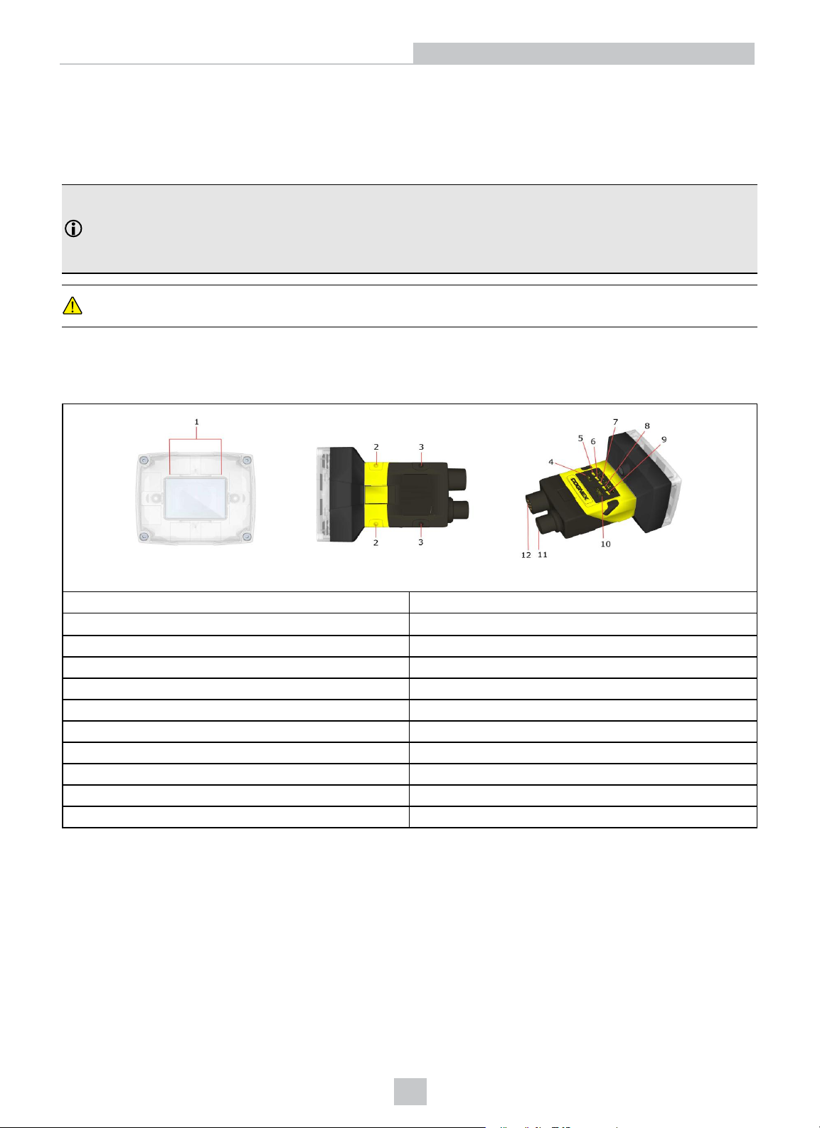
The following image shows the built-in lighting system and other features of the vision sensor.
1 Illumination LEDs
2-3
4
5
6
7 Pass/Fail indicator (LED4 Green/LED4 Red)
8
9
10
11
12
Mounting holes (M3 x 3.5mm)
Trigger button
Power indicator
Trigger status indicator
Network status indicator
Error indicator
Tune button (unsupported)
Power, I/O and RS-232 connector
Ethernet connector
(LED5 Yellow)
11
 Loading...