

Cognex DataMan 8072, DMV-8072V-S-0200, DataMan 8072V, DMV-8072V-S-0100, DMV-8072V-0200 Reference Manual
...
DataMan
®
8072 Handheld
Verifier
Reference Manual
06/07/2018
Revision: 5.7.7.140

Legal Notices
The software described in this document is furnished under license, and may be used or copied only in accordance with
the terms of such license and with the inclusion of the copyright notice shown on this page. Neither the software, this
document, nor any copies thereof may be provided to, or otherwise made available to, anyone other than the licensee.
Title to, and ownership of, this software remains with Cognex Corporation or its licensor. Cognex Corporation assumes
no responsibility for the use or reliability of its software on equipment that is not supplied by Cognex Corporation.
Cognex Corporation makes no warranties, either express or implied, regarding the described software, its
merchantability, non-infringement or its fitness for any particular purpose.
The information in this document is subject to change without notice and should not be construed as a commitment by
Cognex Corporation. Cognex Corporation is not responsible for any errors that may be present in either this document or
the associated software.
Companies, names, and data used in examples herein are fictitious unless otherwise noted. No part of this document
may be reproduced or transmitted in any form or by any means, electronic or mechanical, for any purpose, nor
transferred to any other media or language without the written permission of Cognex Corporation.
Copyright © 2018. Cognex Corporation. All Rights Reserved.
Portions of the hardware and software provided by Cognex may be covered by one or more U.S. and foreign patents, as
well as pending U.S. and foreign patents listed on the Cognex web site at: http://www.cognex.com/patents.
The following are registered trademarks of Cognex Corporation:
Cognex, 2DMAX, Advantage, AlignPlus, Assemblyplus, CheckitwithChecker, Checker, CognexVisionforIndustry,
CognexVSOC, CVL, DataMan, DisplayInspect, DVT, EasyBuilder, Hotbars, IDMax, In-Sight, LaserKiller, MVS-8000,
OmniView, PatFind, PatFlex, PatInspect, PatMax, PatQuick, SensorView, SmartView, SmartAdvisor, SmartLearn,
UltraLight, VisionSolutions, VisionPro, VisionView
The following are trademarks of Cognex Corporation:
The Cognex logo, 1DMax, 3D-Locate, 3DMax, BGAII, CheckPoint, CognexVSoC, CVC-1000, FFD, iLearn, In-Sight
(design insignia with cross-hairs), In-Sight2000, InspectEdge, Inspection Designer, MVS, NotchMax, OCRMax,
PatMaxRedLine, ProofRead, SmartSync, ProfilePlus, SmartDisplay, SmartSystem, SMD4, VisiFlex, Xpand
Portions copyright © Microsoft Corporation. All rights reserved.
Portions copyright © MadCap Software, Inc. All rights reserved.
Other product and company trademarks identified herein are the trademarks of their respective owners.
2
Legal Notices

Table of Contents
Legal Notices 2
Table of Contents 3
Symbols 5
Getting Started 6
About DataMan 8072V 6
DataMan 8072V Kits 6
DataMan 8072V Accessories 8
Cables 8
Physical Layout of the DataMan 8072V Verifier 9
Setting Up the Verifier 10
Install the DataMan SetupTool 13
DataMan 8072V Specifications 13
DataMan 8072V Imager Specifications 13
LED Wavelengths 13
Calibration 13
Using Your DataMan 8072V Verifier 15
Verifying a 2D Barcode 15
Selecting Regions 17
Examining the Results 17
Main 17
General Characteristics 18
Data Detail 18
Quality Detail 19
Advanced Detail 19
Histogram 20
Report 22
User Interface 24
Toolbar 24
Adjusting the Focus Height 24
Illumination Icons 26
Settings 27
Accessing the Settings Menu 27
Application Settings 27
Reporting Settings 33
Grading Standards and their Parameters 36
ISO/IEC 15415 Grading Parameters 36
ISO 29158 (AIM-DPM) 2006 Grading Parameters 40
Traditional (Non-Graded) Parameters 41
Cleaning/Maintenance 43
Cleaning the Reader Housing 43
Cleaning the Reader Lens Cover 43
Regulations/Conformity 44
3
Table of Contents

中 国 大 陆 RoHS (Information for China RoHS Compliance) 45
Precautions 46
4
Table of Contents

Symbols
The following symbols indicate safety precautions and supplemental information.
WARNING: This symbol indicates the presence of a hazard that could result in death, serious personal injury or
electrical shock.
CAUTION: This symbol indicates the presence of a hazard that could result in property damage.
Note: Notes provide supplemental information about a subject.
Tip: Tips provide helpful suggestions and shortcuts that may not otherwise be apparent.
5
Symbols

Getting Started
About DataMan 8072V
The DM8072V verifier is designed to change the direct part mark (DPM) barcode verification experience. The versatile
DM8072V is packed with powerful lighting options, a fast processing engine, and a high-resolution camera to capture
and grade even the most difficult DPM barcodes up to four times quicker than other verifiers on the market. As the only
DPM verifier with 30, 45 and 90-degree lighting options, the DM8072V can easily illuminate codes on textured, curved,
and even recessed surfaces. Grade Data Matrix barcodes against ISO and application standards with easy to read
results displayed on the DataMan Setup Tool software. The all-new user interface provides more detailed reporting and
diagnostic capabilities than ever before.
The DataMan 8072V verifiers are available with the following communication options:
l Ethernet
l USB
The DataMan 8072V verifiers provide the following features:
l Accurate barcode verification according to ISO global standards
l 2D Imager with integrated illumination
l Repeatable and accurate results
l Calibrated and traceable to NIST standards
l Easy-to-use software interface
l Detailed reporting
l Export of verification results in Adobe PDF™
l Consistent results independent of operator training or skill
l Adjustable height stand with Focus Indicator (available as an option)
DataMan 8072V Kits
The DataMan 8072V Verifier is available in the following kits:
Model number Description
6
Getting Started

DMV-8072V-S-0200 DataMan 8072V Verifier Ethernet Kit with Stand:
- 8072V Verifier
- Standoff
- Ethernet Slide-In
- Ethernet Cable Attachment
- Standard Ethernet Cable
- POE Injector
- Basic Calibration Card
- Stand Accessory
DMV-8072V-S-0100 DataMan 8072V Verifier USB Kit with Stand:
- 8072V Verifier
- Standoff
- USB Slide-In
- USB Cable
- Power Supply
- Basic Calibration Card
- Stand Accessory
DMV-8072V-0200
DataMan 8072V Verifier Ethernet Kit:
- 8072V Verifier
- Standoff
- Ethernet Slide-In
- Ethernet Cable Attachment
- POE Injector
- Basic Calibration
DMV-8072V-0100 DataMan 8072V Verifier USB Kit
- 8072V Verifier
- Standoff
- USB Slide-In
- USB Cable
- Power Supply
- Basic Calibration Card
DMV-8072V-0000 DataMan 8072V Verifier Kit No Slide-In
- 8072V Verifier
- Standoff
- Basic Calibration Card
DMV-8072V-S-0000 DataMan 8072V Verifier Kit with Stand No Slide-In
- 8072 Verifier
- Standoff
- Stand Accessory
- Basic Calibration Card
DataMan 8072V verifier and stand-off Ethernet or USB slide-in
7
Getting Started

Stand accessory Calibration card
DataMan 8072V Accessories
Ethernet slide-in DMCM-ENETM-00
Serial/USB 2.0 slide-in DMCM-USB2EN-00
Power Supply for USB 2.0 Slide-In DM100-PWR-000
POE hub CPS-AC-POE1A-US
Stand Accessory DMV-8072V-STAND
Cables
USB Cable for USB 2.0 Slide-In, 2.5 m
DM8500-USBC-02
Ethernet Cable for Ethernet Slide-In , 5 m DM8000-ECABLE-05
Standard Ethernet Cable CBL-C10E
8
Getting Started

Physical Layout of the DataMan 8072V Verifier
WARNING: LASER LIGHT, DO NOT STARE INTO BEAM
1 Imager and Lens Optical System
2 Illumination
3 Removable Standoff
4 Trigger (press and release)
5 Lanyard hook
6 Indicator light
7 Communication module insertion point
Status indicator Light:
l Communication:
o
GREEN= good verification
o
RED = bad verification
Note: For more information on the DataMan 8072V hardware, see the DataMan 8072 Verifier Quick Reference
Guide.
9
Getting Started

Setting Up the Verifier
To be able to connect to your reader on your computer, you must perform the following steps:
1.1. Install the DataMan Setup Tool on your computer.
2. Select the connection type: Ethernet or USB; and connect the appropriate cabling.
3. Power on your device(s).
4. Open the DataMan Setup Tool and connect to your DataMan 8072V verifier. The TruCheck verification
application automatically opens after the unit is successfully connected
10
Setting Up the Verifier

Tip: If the TruCheck verification window does not automatically open, or is closed during use, it can be re-opened
by selecting the View tab in the Setup Tool and selecting the icon for “TruCheck Window”.
For some computers, connecting to a verifier using a USB 2.0 slide-in requires additional steps. Some Windows PC’s
have USB Selective Suspend enabled by default and this must be disabled for the USB interface to work correctly. If this
occurs, follow these steps to correct the problem:
1. Select the Start button in the bottom left corner of your computer and select the Settings icon.
2. Select System, then select Power & sleep.
3. In the Power & sleep menu, select Additional Power Settings. This option is found on the right side of the window
under Related Settings. This will open the Power Options menu.
4. In the Power Options menu, select “Change plan settings” on the power plan that is currently selected. This will
open the Edit Plan Settings menu.
11
Setting Up the Verifier

5. In the Edit Plan Settings menu, select “Change advanced power settings”. This will open the Power Options
menu.
6. In the Power Options menu, locate USB Settings under the Advanced Settings tab. Select [+] for both “USB
Settings” and “USB selective suspend setting”. Under this selection, there will be options for On Battery and
Plugged In. Set both to “Disable” by selecting from the drop down menu.
7. Select OK and then restart your computer. The problem will not be solved until you restart your computer. Open
the Setup Tool and plug in the USB 2.0 Slide-in. The 8072V should now appear in the device list.
8. If you've done everything as describe above, but still cannot see the 8072V, Go to Start- > Devices and Printers ->
LAN7500 [right-click] -> Troubleshoot and see if that fixes the problem.
9. If not, open a web browser and search for `LAN 7500 USB to Ethernet Adaptor for windows X' [X = 7 or 10 or
latest edition being used] and download it. Reboot reader and try again.
12
Setting Up the Verifier

Install the DataMan SetupTool
1. Check the DataMan Release Notes for a full list of system requirements.
2. Download the DataMan Setup Tool from http://www.cognex.com/support/dataman and follow the on-screen
steps.
3. Connect the DataMan 8072V to your PC.
4. Launch the DataMan Setup Tool and click Refresh. The verifier appears under COM ports or Network devices.
5. Select your DataMan 8072V from the list and click Connect.
DataMan 8072V Specifications
Weight
400 g (including grip assembly with battery)
Operating Temperature 0ºC — 45ºC (32ºF — 113ºF)
Storage Temperature
0ºC — 60ºC (32ºF — 140ºF)
Maximum Humidity 95% (non-condensing)
Environemntal IP65
Codes
2-D barcodes: Data MatrixTM(IDMax and IDQuick: ECC200)
Power Supply
Requirements
USB: bus powered (optionally: external 6W max LPS or NEC class 2 power supply +5V +6V DC)
ETH: Class 2 PoE supply IEEE 802.3af (connect only to PoE networks without routing to the
outside plant)
Inrush current peak
5A maximum
Duration: approx. 30μs
Ethernet 10/100 Base-T FULL/HALF DUPLEX, IEEE 802.3
DataMan 8072V Imager Specifications
Specification DataMan 8072V Imager
Image Sensor
1/3 inch CMOS global shutter
Image Sensor Properties
3.75 μm square pixels
Image Resolution (Pixels)
1280 x 966
Lens Type
12 mm F:4 S-mount lens
LED Wavelengths
The following table shows LED types and the related wavelengths:
LED λ [nm]
RED 660
Calibration
Before starting to use the DataMan 8072V verifier for verifying barcodes, the device needs to be calibrated. Perform the
following steps to calibrate the unit.
13
Setting Up the Verifier

1. Click on the Calibration icon in the top left corner.
2. Enter the Rmax and Rmin values from the calibration card.
3. Select the Center Target button. A live image appears in the Calibration screen. Center the verifier over the
Master Symbol on the Data Matrix symbol of your traceable calibration card.
4. Once the symbol is centered in the field of view, select Start Calibration.
5. The verifier will go through a series of lighting calibrations. After a successful calibration, the following window
pops up:
14
Setting Up the Verifier

Using Your DataMan 8072V Verifier
Verifying a 2D Barcode
Perform the following steps to verify a Data Matrix barcode:
1. Navigate to the Main tab.
2. Select Go Live, and center your symbol in the screen. Alternately, press and release the trigger button to Go Live.
Note: After selecting Go Live, the button will change to Verify.
3. If necessary, draw a selection region around the barcode to be verified (see Selecting Regions).
Note: The region must be drawn around the outside perimeter of the code including quiet zones. More
information on properly defining regions is explained in Selecting Regions.
15
Using Your DataMan 8072V Verifier

4. Once you have made your region selection, select Verify or press and release the trigger button on the verifier to
begin verification.
Note: The following screenshot shows a successful 2D barcode verification. Depending on grading and
application standards, additional details will be displayed.
Note: The tool bar buttons and tabs shown on the screen are useful for in-depth analysis of barcodes. For more
information, see the Examining the Results section.
16
Using Your DataMan 8072V Verifier

Selecting Regions
Specifying regions in the live image may be required for the following reasons:
l If the code is off center.
l Speed up the verification process on verifiers with large fields of view. Defining a small sampling area will
increase the speed.
l To restrict a region used to adjust the image brightness when grading according to AIM-DPM (ISO/IEC 29158).
l To specify a barcode for verification when more than one barcode is present in the field of view.
If you do not define a region, the whole image will be used.
In order to define a region, position your cursor where you want the region to start, hold the left mouse button down and
begin drawing a box by moving the mouse. Release the button when you are done.
For Data Matrix symbols, the region should be drawn surrounding the entire code. The verifier will need the entire finder
pattern, including quiet zones, within the selection to properly grade the code.
Examining the Results
This section details in a tab-by-tab fashion how the results of the verification can be viewed and analyzed.
Main
After verification, the Main menu shows a snapshot of the verification results.
Acceptance Criteria: This box will provide a Pass/Fail grade for the barcode and is dependent on the Application
Standard selected.
Data: This box will show the decoded data. If the data is longer than the box provided, the data will develop a scroll bar
to show the remaining data.
Overall Grade: This box will show the overall grade results for the barcode as both a letter grade and numeric grade in
the format of A (4.0). In addition, a Formal Grade is provided in the format “Grade/Aperture/Wavelength/Lighting”. For
example, a Formal Grade of “4.0/08/660/45” is interpreted as receiving a grade of 4.0 using 8 mil aperture (0.2 mm), 660
nm wavelength, and 45° lighting.
Format Grade: This box will provide the Format Grade of the barcode and is dependent on the either Application
Standard or Data Format Check criteria selected.
17
Using Your DataMan 8072V Verifier

Symbology: This box will report what type of symbology was detected and used for verification.
Grade Parameters: This box will provide information on the Quality Parameters grading for the barcode. More detailed
information for these parameters is found on the Quality Detail tab. If the Grade Parameters is not visible on the Main
menu, select the arrow on the right side of the menu to open it.
General Characteristics
The General Characteristic tab shows the physical characteristics of the verified barcode.
The following image shows the characteristics of a Data Matrix barcode:
The Contrast Uniformity value, which is important for verifying conformance with ISO/IEC 15426-2 is also shown in this
tab. Some of the contents of this screen depends on the symbology and settings on the Report Settings menu.
Data Detail
When viewing the Data Detail tab, all of the data content of the symbol is shown. Detail depends on the symbology and
the selected application standards.
The following screen shows a Data Matrix with encoding information:
18
Using Your DataMan 8072V Verifier

When a data checking failure occurs, a message will indicate the cause of the failure. For example, if a check digit is
incorrect, a message will indicate the expected check digit value. When an error is detected, it is reported and the
parsing is stopped.
The following screen shows the data Matrix with encoding information along with a depiction of the symbol to the right
showing each module.
When the cursor is placed over the codewords reported in the Data Matrix Codeword table, the eight modules of that
codeword are highlighted within the image depiction to show where the data is encoded within a data matrix symbol.
Quality Detail
The measured quality parameters are shown in this tab, and the formal grade is listed here. Different symbologies and
quality grading standards will display pertinent data here.
For example, the following screen shows the characteristics of a 2D Data Matrix barcode graded according to ISO
15415.
Detailed explanation on the grading standards can be found in Grading Standards and their Parameters.
Advanced Detail
This tab shows in-depth information on the verified code. The particular info shown depends on the type of the verified
barcode.
The below example shows the modulation values from a Data Matrix symbol:
19
Using Your DataMan 8072V Verifier

Detailed explanation on modulation calculation can be found in the Grading Standards and their Parameters under the
ISO 15415 and AIM-DPM grading explanations.
Histogram
The Histogram tab shows the analysis of each cell’s reflectivity and associated grade.
The horizontal axis on the histogram represents the brightness level, with the dark elements on the left and the bright
elements on the right. The brighter the element is, the further to the right it will be. The height of each bar represents the
number of elements with the brightness associated with its position on the horizontal axis.
The top graph is a histogram representing the brightness of all the pixels in the image. The bottom graph only represents
the center of modules in the symbol. As expected, the bottom graph does not contain elements which are not either
definitively dark or definitively bright. While all the dark or bright modules are not exactly the same in brightness, they are
relatively close to each other and that is why the bars are grouped together. In the upper histogram, some pixels, which
are in between dark and bright, are represented. These pixels are typically on the border between dark and light
modules and thereby obtain a middle value of brightness.
20
Using Your DataMan 8072V Verifier

The horizontal axis contains markers showing the global threshold (tall line) and the separation between B and C, and
between C and D modulation levels for both dark and light elements. Note that when grading according to ISO/IEC
TR29158 (AIM-DPM), the histogram will be labeled slightly differently. The 0% and 100% labels on the horizontal axis
will be located at the means of the dark and light lobes of the histogram and there will be no “C” level because the DPM
grading method uses only A, B, D and F levels for Cell Modulation.
21
Using Your DataMan 8072V Verifier

Report
This tab shows a preview of the report:
The contents of the report can be customized to include more or less detail. Customization can be done in the Reporting
Settings menu, as well as setting options for electronically saving reports and how they are named. This report can be
printed and saved electronically.
Note: Adobe PDF™ Reader is required in order to view the report in the Report tab.
Adobe Settings Change
A security setting needs to be set in order to use Adobe with the TruCheck firmware.
1. Open Adobe -> Edit -> Preferences.
2. Select Security (Enhanced) from the menu on the left of the Preferences menu.
22
Using Your DataMan 8072V Verifier

3. Uncheck the box for Enable Enhanced Security.
4. Select OK to save change.
23
Using Your DataMan 8072V Verifier

User Interface
Toolbar
Icon Function
Settings: Opens up the settings menu allowing changes to be made to both the Application Settings
and Reporting Settings menu. See Settings section for information.
Calibration: Opens up the calibration window so that the unit can be calibrated. See Calibration
section for more information.
Grid & Modulation Circles: When selected, this applies a grid and/or modulation circles to the image
after verification. By using the drop down menu options, a selection can be made to apply a Real
Grid, an Ideal Grid, or both. In addition, a selection is made to either show Mod Circles Filled or Mod
Circles Outlined. When this icon is unselected, neither Grid nor Mod Circles is shown on the image.
Original Image: Shows the original image used for verification.
Focusing Indicator: When using the verifier with the optional stand, enabling this feature shows a
focusing indicator in the image window that is used to adjust the height of the stand so that the
verifier views the target barcode at the proper focal distance. See Adjusting the Focus Height section
for more information.
Adjusting the Focus Height
The 8072V verifier can be equipped with an optional adjustable height stand that is guided by a focusing indicator.
When using the optional stand, prior to verifying, the verifier must be adjusted to the proper height above the target to
ensure proper focus
To adjust the focus, place the symbol directly under the verifier and press the “Go Live” button. A live image will appear
on the screen. You will see a “target” circle in the center of the image window. Additionally, an image of the “indicator
spot” will appear somewhere on the image along the vertical center axis. Note that it is possible for the indicator spot to
fall outside the field of view, so you may need to adjust the height of the imager before it begins to appear in the image
window.
24
User Interface

Carefully rotate the crank on the top of the verifier until the indicator spot is in the same position as the circle at which
point the circle turns green. The unit is focused when the target circle is depicted in green.
If you attempt to verify when the target circle is not green, you will be prompted to focus by a “Focus Warning” pop-up
window. This window provides the option to select “OK” which is provided as a way to override the focus indicator
requirement in cases when the indicator spot is physically blocked by a part of a real object on which a barcode is to be
verified. Unless instructed to do so, you should always achieve the correct focus position and not use the override “OK”
option.
25
User Interface

Illumination Icons
Direct Part Mark (DPM) verifiers have multiple lighting options to grade according to various grading methodologies and
standards (such as AIM-DPM). When verifying using ISO15415, only the 45Q lighting option is available for selection;
when verifying using ISO 29158 (AIM-DPM), all lighting options are available for selection.
Note: Some lighting options are not allowed in some application standards so you should only select options that
provide you with a result that is valid for your application. It is common to use AIM-DPM as the basis for grading
when working with DPM symbols and lighting other than 45-degree light from four sides.
Icon Function
This icon selects 45° illumination. 45° four-sided illumination is used primarily for labels. This illumination is
either not reported or is reported as 45Q. (If illumination is not reported, it is assumed to be 45Q).
This icon selects 30° illumination from four sides. It may reduce glare from some substrates, which cause
poor Symbol Contrast or Modulation grading. This illumination is reported as 30Q and is used primarily for
DPM applications.
These icons select 30° two-sided illumination. This illumination can be from either the North/South or
East/West. These are useful on cylindrical surfaces and should be selected parallel to the axis of the
cylinder. This illumination is reported as 30T.
This icon allows the user to select one side of the 30° lighting to be used. By using the drop down menu, one
of the four sides for 30° lighting can be selected. If this lighting option is selected but no individual lighting
side is selected on the drop down menu, the top 30° lighting is used. This illumination is reported as 30S.
This icon selects 90° diffuse illumination and works well on very shiny substrates and Dot Peen Applications.
This illumination is reported as 90.
26
User Interface

Settings
Accessing the Settings Menu
To access Settings, select the Settings icon in the upper left hand corner of the interface.
Application Settings
The contents of the settings window will depend upon the Application Standard that you select. This is because the
application standard automatically selects many parameters. The “Generic” Application standard allows you to select all
adjustable verification and process parameters in a custom way. By selecting a pre-defined application standard, you
can be assured that the verifier will use appropriate grading parameters for your application. For example, when using
pre-defined application standards, you do not need to specify an Aperture Size because it will always be chosen in
accordance with the application standard automatically.
Application Standards:
Application standards configure the verifier to grade according to pre-defined rules established by an industry standards
body (such as GS1) or other industry requirements such as MIL-STD 130 (UID).
Select Standard:
Users may specify the Application Standard by selecting one of the options provided in the drop down box. The rest of
the setting options that are available within each of these standards will be described in detail below:
27
Settings
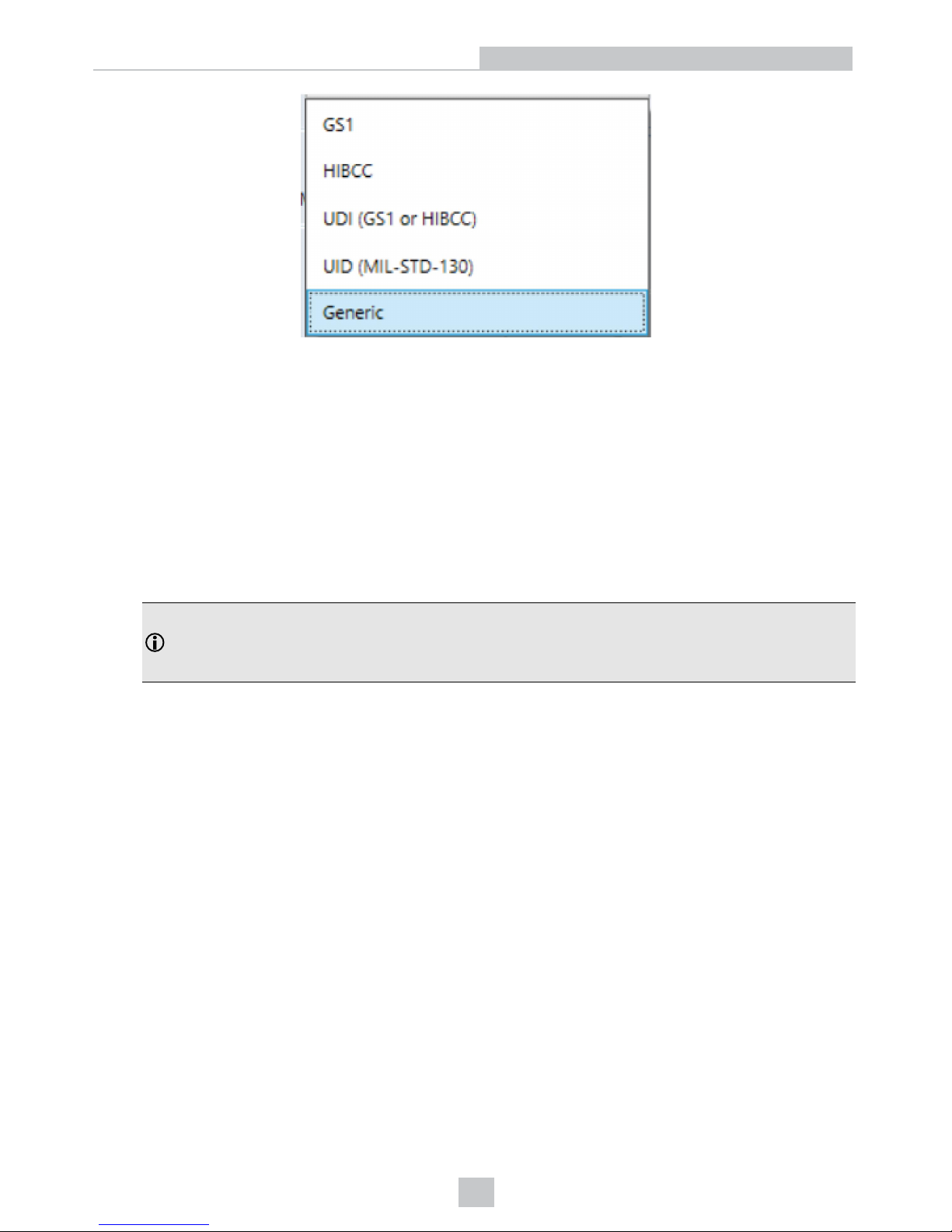
l GS1
The GS1 Application standard allows barcodes to be verified according to GS1 General Specifications. GS1
General Specifications contain several categories of applications which are described in its Tables 1-11. You can
select from among these tables to specify the application category for your barcodes. For example, if you are
printing for point of sale (POS) applications, Table 1 is applicable to your barcodes. Alternately, if you are printing
UDI barcodes, Table 6 is applicable to your barcodes. If you are unsure of which table you should choose, you
can choose Auto (Warn if Ambiguous). When using the Auto option, the verifier will determine one or more
applicable tables based on the X-dimension of the decoded symbol and the grading standard (ISO/IEC 15415 or
ISO/IEC 29159 (AIM DPM). The report will indicate the table that was selected. If more than one table is
applicable, the verifier will give a warning when the information is ambiguous and list the tables that are
applicable, it will choose the most likely table to be applied, and will identify the table that was applied in the
report.
Note: Since the X-dimension of the decoded symbol is used to deduce which table applies, it may be
incorrect if your X-dimension is outside of the range allowed in your application. To be sure that the verifier
is checking all of the proper requirements for your application, you should select the Table in the GS1
General Specifications that apply to your application.
The GS1 table used is reported in the Notes section on the report. Refer to the tables provided in the GS1
General Specifications Standard for more information on the tables used for analysis.
In addition to which Table of the GS1 General Specifications to use, you can also specify ISO/IEC 15415 grading
(generally used for labels) or ISO/IEC 29158 (AIM-DPM) as the grading method.
28
Settings

l MIL-130-STD UID
This application standard will properly report the quality standard used to grade the code and the data structure
used in (Construct 1 or Construct 2) for UID marks specified in MIL-STD 130. The MIL-STD spells out what grades
are acceptable and requirements for data format.
You must specify either ISO 15415 grading or ISO 29158 (AIM-DPM) grading.
You may select Dot Peen if it is applicable.
29
Settings

l UDI/HIBC
This application standard checks symbols that meet UDI requirements using either GS1 or HIBCC guidelines.
You must specify either ISO 15415 grading or ISO 29158 grading.
You may select Dot Peen if it is applicable.
Since the data content required for UDI compliance varies depending upon the medical device, only the data
format (but not what content is present or missing) is validated. Data will automatically be validated in accordance
with GS1 formatting rules, or in accordance with HIBCC formatting rules.
Generic:
The Generic standard option can be applied when you are grading a barcode that is not expected to adhere to any predefined industry conformance standard, and so it can be customized with specific settings for:
l Aperture Size
l Minimum Acceptable Pass Grade
l Minimum and Maximum X-dimension
l Grading Method: ISO 15415 or ISO 29158
30
Settings

l Data Parsing and Validation
Grading Standard:
For any Application Standard selected, a choice must be made for to use either ISO 15415 or ISO 29158 (AIM-DPM)
depending on your application.
l ISO 15415: Reports and displays according to ISO/IEC 15415 which is typically used for label based barcodes.
l ISO 29158 (AIM-DPM): Select this if you want to utilize the AIM-DPM verification standard. This can be selected
with or without the Dot Peen selection. When using AIM-DPM Grading, the aperture setting is not used, instead
the X-Dimension Range is used in accordance with the AIM-DPM methodology.
Data Format Check:
A selection can be made to apply a specific “Data Format Check” criteria to the data content of the barcode or leave the
option as None. If a specific Data Format Check is applied, a Data Format Check grading box will appear on the main
screen of the User Interface to show the Pass/Fail grade provided and a Data Format Check table is provided on the
report showing more detailed parsing information.
l GS1: This option checks the format of the data against GS1 formatting rules. These barcodes generally begin with
a Function 1 <F1> character.
l HIBCC: This option checks the format of the data against HIBCC formatting rules. These barcodes generally
begin with a + character.
31
Settings

l ISO/IEC 15434: This option checks data for many industry standards which encode information using ISO/IEC
15434 data structures. These barcodes generally begin with the sequence )]><RS>nn<GS> where nn are two
digits which are typically 05, 06 or 12. MIL-STD 130 and some shipping container applications use this formatting
style
Dot Peen:
Use this option for barcodes created with the dot peening process, which is a process where dots are peened onto a
metal surface. Select Dot Peen to use the AIM-DPM “Stick algorithm” to connect dots.
Min X-Dimension (mils):
Users can set a minimum x-dimension value that is allowed during verification. The lowest value that can be set is 1 mil.
Any barcode that falls below the minimum x-dimension set will receive a grade of “FAIL (X Dimension out of Range)”. If
no minimum x-dimension is specified, the application will default to 5 mils.
Max X-Dimension (mils):
Users can set a maximum x-dimension value that is allowed during verification. The highest value that can be set is 30
mils. Any barcode that is above the maximum x-dimension set will receive a grade of “FAIL (X Dimension out of Range)”.
If no maximum x-dimension is specified, the application will default to 30 mils.
Pass Grade:
Users may simply want to select a minimum passing grade based on a certain letter or numerical value (i.e. C >1.5). Any
barcode verified that does not receive an Overall Grade above the Pass Grade minimum set will receive a grade of Fail
for Pass Grade on the User Interface and Report.
Aperture Setting:
This is the size of the “synthetic aperture” used to produce the “blurred” reference image that is an integral part of ISO
15415 grading. The size of the aperture has a profound effect on the grade and should be chosen with care, according to
the requirements of your application. In general, larger aperture sizes will reduce the sensitivity to defects in printing, but
also reduce the ability to resolve small elements in a barcode. Consequently, the size of the aperture is limited by the Xdimension of your symbols, or conversely the X-dimension of your symbols is limited by the size of your aperture.
Aperture size can be called out in the application specification, quality specification, or both. If you are unsure of the
aperture size to select, you may choose “Auto” and the verifier will use guidance supplied within ISO 15415 to choose an
aperture size based on the X-dimension of the barcode.
The aperture setting is used when grading in accordance with ISO/IEC 15415, but it is not used when grading in
accordance with AIM-DPM. While AIM DPM grading does include a blurred reference image, just like ISO 15415, the
aperture size is dictated by the AIM-DPM grading method automatically to be either 50% or 80% of the symbol Xdimension automatically.
An aperture size must be specified for the Generic standard when using ISO/IEC 15415.
There are three options on the drop down menu box – User Set, Auto 80%, and Auto Aperture.
32
Settings

User Set: The application will allow the user to specify the aperture setting. When User Set is selected, an additional
drop down menu will allow users to select the correct aperture.
Auto 80%: The application will automatically choose an aperture size based on 80% of the x-dimension.
Auto Aperture: The application will automatically choose an aperture size based on the X-dimension in accordance with
the suggestion in ISO/IEC 15415. See table below.
X-Dimension Aperture
Less than 6 mil
02 (2 mil)
6 mil to 7.5 mil
03 (3 mil)
7.5 mil to 10 mil
05 (5 mil)
10 mil to 20 mil
08 (8 mil)
20 mil to 30 mil
16 (16 mil)
More than 30 mil
20 (20 mil)
Note: AIM-DPM grading (ISO/IEC TR 29158) always selects an aperture automatically based on the X- Dimension
of the decoded symbol, which will override the above rules. So, these rules only apply to ISO/IEC 15415 grading,
when Auto Aperture is selected
Reporting Settings
Report Preview: This section shows a preview of the report that will be generated after verification. By selecting or
unselecting boxes in Report Sections, the information shown on the report preview will adjust to reflect the changes
made to what information is shown in the report.
Report Sections: These are the selections that determine what optional sections are printed (or saved in PDF files) on
the reports. This information will appear on the various tabs in the User Interface for viewing, regardless of what selection
is made.
33
Settings

Traditional Parameters: Includes Minimum Reflectance Difference (MRD) in the reported General Characteristics both
in the verification report and on the User Interface. MRD quantifies the minimum difference anywhere across the
barcode. This information is also found in the General Characteristic tab.
Unicode Data: Will include the data field interpreted using Unicode to show foreign language characters. Turn this on
when your barcode contains such characters encoded using Unicode. This information is also found in the Data Detail
tab.
Mod Values: Reports show the individual modulation values from each data cell in the symbol. This information is also
found on both the Data Detail and Advanced Detail tabs.
Image of Symbol: Includes the image used for verification on the verification report. This information is also found on the
General Characteristic tab.
Encodation Analysis: Turns on the reporting of Decoded characters or “codewords” to final output text which can be
useful when encoding errors are present in a 2D symbology. This information is also found on the Data Detail tab.
Codewords: Turns on reporting of the codeword that are directly encoded in the 2D symbol. Codewords which were
correcting by error correction are indicated. This information is also found on the Data Detail tab.
ASCII Values: Turns on the reporting of the encoded ASCII values. This does not affect how unprintable characters are
represented in the decoded data on reports, which is done by a special ASCII Code Representation, for example <CR>
for carriage return which is ASCII value 13. This information is also found on the Data Detail tab. See the ASCII Values
Table
l Decoded Data ASCII Code Representation for unprintable characters: Some barcode can encode ASCII
characters that are unprintable and therefore difficult to represent in the printed reports. A special pattern is used
to represent these characters using a consistent notation of two letters, which represents the ASCII code,
surrounded by brackets.
Reports will show unprintable ASCII values using the following notation:
ASCII Code Value (decimal) ASCII Code name Special Pattern Used
0 NULL <NU>
1 SOH <SH>
34
Settings

ASCII Code Value (decimal) ASCII Code name Special Pattern Used
2 STX <ST>
3 ETX <ET>
4 EOT <EO>
5 ENQ <EN>
6 ACK <AC>
7 BEL <BE>
8 BS <BS>
9 HT <HT>
10 LF <LF>
11 VT <VT>
12 FF <FF>
13 CR <CR>
14 SO <SO>
15 SI <SI>
16 DLE <DL>
17 DC1 <D1>
18 DC2 <D2>
19 DC3 <D3>
20 DC4 <D4>
21 NAK <NK>
22 SYN <SY>
23 ETB <EB>
24 CAN <CA>
25 EM <EM>
26 SUB <SU>
27 ESC <ES>
28 FS <FS>
29 GS <GS>
30 RS <RS>
31 US <US>
Note: The special patterns always consist of two letters, even though the name of the ASCII code sometimes
contains more than two characters (example EOT, BEL, etc.). This is to preserve regular column spacing in the
printed reports and to make it easier to parse the data strings.
Quality Parameters: Enables reporting of a standard’s quality parameters and their corresponding values and grades.
Selecting this is highly recommended, as this information makes visible the reasons for poor results in a standard. This
information is also found on the Quality Detail tab.
ECC Details: Turns on reporting of error correction details. This information is also found on the General Characteristic
tab.
Save Report: Saves reports electronically to the path defined in the field. Use the Browse button to select the pathway to
save the report. The path can be a local hard drive or file server the user when has permission to write to it. The
Reporting Settings selected, as described above, determine what information is contained in the save reports.
35
Settings

Grading Standards and their Parameters
ISO/IEC 15415 Grading Parameters
1. UEC (Unused Error Correction): This is the percentage of error correction capability that is available for further
incorrect modules. The assignment of grade is according to the following table:
UEC % Grade
> 62 A (4.0)
> 50 (but less than 62) B (3.0)
> 37(but less than 50) C (2.0)
> 25 (but less than 37) D (1.0)
< 25 F (0)
2. SC (Symbol Contrast): This is the difference in reflectivity between the brightest module and the darkest
module. The assignment of grade is according to the following table:
SC% Grade
> 70 A (4.0)
> 55 (but less than 70) B (3.0)
> 40 (but less than 55) C (2.0)
> 20 (but less than 40) D (1.0)
< 20 F (0)
3. MOD and RM (Modulation): This is a grade based on the amount of variability in reflectivity of the modules. A
multi-step process is used to get the modulation grade. First, the reflectivity of each module is compared to the
global threshold and the overall symbol contrast according to the following formula:
MOD = 2 * (abs(R - GT)) / SC
The Global Threshold GT is the midpoint between the reflectance of the brightest module and the reflectance of the
darkest module. Next, the grade level for each module is determined from the MOD value according to the following
table:
MOD % Grade
> 50 A (4.0)
> 40 (but less than 50) B (3.0)
> 30 (but less than 40) C (2.0)
> 20 (but less than 30) D (1.0)
< 20 F (0)
Finally, the value of the grade for the Modulation parameter will be the highest modulation level for which the modules
meeting that level will result in a notional Unused Error Correction grade of that level or higher. The module with the
lowest MOD is reported as Contrast Uniformity (CU) in General Characteristics to facilitate conformance testing to the
requirements of ISO/IEC 15426-2.
The RM parameter works in a similar way, except that for modules which were corrected as errors by error correction, the
MOD% is taken as 0 and counts as F in the final evaluation of the Modulation parameter grade according to the notional
Unused Error Correction grade.
36
Grading Standards and their Parameters

4. ANU (Axial Non-uniformity): This is the amount of “out of square” the modules are or in other words, a measure
of the overall aspect ratio of the symbol. Note that for rectangular symbols which are supposed to be non-square,
the ANU parameter reports the deviation from its “correct” aspect ratio.
ANU % Grade
≤ 6 A (4.0)
< 8 (but more than 6) B (3.0)
< 10 (but more than 8) C (2.0)
< 12 (but more than 10) D (1.0)
> 12 F (0)
5. GNU (Grid Non-uniformity): This is the worst-case distance between the calculated center of a module and the
ideal location for the center of the module based on perfectly evenly spaced modules. The calculated center of
the module is determined using clock track edges in accordance with the reference decode algorithm. The value
is reported as a percentage of a module size.
GNU % Grade
≤ 38 A (4.0)
< 50 (but more than 38) B (3.0)
< 63 (but more than 50) C (2.0)
< 75 (but more than 63) D (1.0)
> 75 F (0)
6. FPD (Fixed Pattern Damage): This is the overall grade for all the fixed pattern components. This grade is equal
to the lowest grade of all the components listed below. The following is a list of components of the finder pattern.
7. LLS (Left ‘L’ Side): This is a grade based on imperfections in the left ‘L’ side of the finder pattern. There are two
checks required to pass. The first requires gaps to be three modules or less and that gaps are separated by
stretches of at least four correct modules. The second assigns a grade based on the overall percentage of correct
modules according to the following table:
% of incorrect modules Grade
0 A (4.0)
< 9 (but more than 0) B (3.0)
< 13 (but more than 9) C (2.0)
< 17 (but more than 13) D (1.0)
> 17 F (0)
The grade is the highest modulation level in which the first (gap test) passes and the correct module percentage results
in a grade of that level or higher.
8. BLS (Bottom ‘L’ Side): This is a grade based on imperfections in the bottom ‘L’ side of the finder pattern (see Left
‘L’ Side).
9. LQZ (Left Quiet Zone): This is a grade based on imperfections in the quiet zone, which is a one-module area to
the left of the left ‘L’ side. The grade is based on the percentage of modules, which are correct using the same
grading table as for the ‘L’ sides.
10. BQZ (Bottom Quiet Zone): This is a grade based on imperfections in the quiet zone, which is a one-module area
below the bottom ‘L’ side.
37
Grading Standards and their Parameters

11. TQZ (Top Quiet Zone): This is a grade based on imperfections in the quiet zone, which is a one-module area
above the top clock track.
a. ULQZ (Upper Left Quiet Zone): This is the top quiet zone above the upper left quadrant (Used only for 2
and 4 quadrant symbols, this is the grade based on the segment of the quiet zone above the top clock
track of the left quadrant).
b. URQZ (Upper Right Quiet Zone): This is the top quiet zone above the upper right quadrant (Used only for
2 and 4 quadrant symbols, this is the grade based on the segment of the quiet zone above the top clock
track of the right quadrant).
12. RQZ (Right Quiet Zone): This is a grade based on imperfections in the quiet zone, which is a one-module area to
the right of the Right Clock Track.
a. RUQZ (Right Quiet Zone to the right of the upper right quadrant): Only for 2 and 4 quadrant symbols,
this is the grade based on the segment of the quiet zone to the right of the upper right quadrant.
b. RLQZ (Right Quiet Zone to the right of the lower right quadrant): Only for 4 quadrant symbols, this is the
grade based on the segment of the quiet zone to the right of the lower left quadrant.
13. TTR (Top Transition Ratio): This is a grade based on imperfections in the top clock track, with relation to its
adjoining quiet zone. The ratio is the number of transitions from light to dark or dark to light in the quiet zone
divided by the number of transitions in the clock track. Since the number of transitions in the quiet zone should be
zero, the ideal value for this parameter is zero. However, a small number of transitions can be tolerated as long
as the ratio remains relatively low. As the number of teeth in the clock track increases (larger symbols) more
transitions in the quiet zone can be tolerated. Also, more transitions in the clock track (which are really
imperfections) will tend to improve this measurement. The grading scheme for this transition ratio is:
Transition Ratio % Grade
< 6 A (4.0)
< 8 (but more than 6) B (3.0)
< 10 (but more than 8) C (2.0)
< 12 (but more than 10) D (1.0)
> 12 F (0)
The value of the grade will be the highest modulation level for which the ratio gives a grade from the above table
of that modulation level or higher.
a. ULQTTR (Transition ratio for Upper Left Quadrant Top Clock Track): Only for 4 quadrant symbols, this
is the grade based on the clock track segment at the top of the upper left quadrant. For a 2 quadrant
symbol, this will be labeled LQTTR.
b. URQTTR (Transition ratio for Upper Right Quadrant Top Clock Track): Only for 4 quadrant symbols, this
is the grade based on the clock track segment at the top of the upper right quadrant. For a 2 quadrant
symbol this will be labeled RQTTR.
c. LLQTTR (Transition ratio for Lower Left Quadrant Top Clock Track): Only for 4 quadrant symbols, this is
the grade based on the clock track segment at the top of the lower left quadrant.
d. LRQTTR (Transition ratio for Lower Right Quadrant Top Clock Track): Only for 2 and 4 quadrant
symbols, this is the grade based on the clock track segment at the top of the lower right quadrant.
RTR (Right Transition Ratio): Transition ratio (see Top Transition Ratio) for the right clock track in relation to the
right quiet zone
38
Grading Standards and their Parameters

14. .ULQRTR (Transition ratio for Upper Left Quadrant Right Clock Track): Only for 2 and 4 quadrant symbols, this
is the grade based on the clock track segment to the right of the upper left quadrant. For a 2 quadrant symbol, this
will be labeled LQRTR
a. URQRTR (Transition ratio for Upper Right Quadrant Right Clock Track): Only for 2 and 4 quadrant
symbols, this is the grade based on the clock track segment to the right of the upper right quadrant. For 2
quadrant symbols, this will be labeled RQRTR.
b. LLQRTR (Transition ratio for Lower Left Quadrant Right Clock Track): Only for 4 quadrant symbols, this
is the grade based on the clock track segment to the right of the lower left quadrant.
c. LRQRTR (Transition ratio for Lower Right Quadrant Right Clock Track): Only for 4 quadrant symbols,
this is the grade based on the clock track segment to the right of the lower right quadrant.
15. TCT (Top Clock Track): This is a grade based on imperfections in the top clock track. Some imperfections in the
clock track can be tolerated. However, the rule that must be maintained for a passing grade is that three out of
every five modules (on a consecutively rolling window of five modules) must be correct. The value of the grade
will be the highest modulation level for which this test passes.
a. ULQTCT (Top Clock Track for Upper Left Quadrant): Only for 2 and 4 quadrant symbols, this is the
grade based on the clock track segment at the top of the upper left quadrant. For 2 quadrant symbols this
will be labeled LQTCT.
b. URQTCT (Top Clock Track for Upper Right Quadrant): Only for 2 and 4 quadrant symbols, this is the
grade based on the clock track segment at the top of the upper right quadrant. For 2 quadrant symbols this
will be labeled RQTCT.
c. LLQTCT (Top Clock Track for Lower Left Quadrant): Only for 4 quadrant symbols, this is the grade
based on the clock track segment at the top of the lower left quadrant.
d. LRQTCT (Top Clock Track for Lower Right Quadrant): Only for 4 quadrant symbols, this is the grade
based on the clock track segment at the top of the lower right quadrant.
16. RCT (Right Clock Track): This is a grade based on imperfection in the right clock track (see Top Clock Track).
a. ULQRCT (Right Clock Track for Upper Left Quadrant): Only for 2 and 4 quadrant symbols, this is the
grade based on the clock track segment to the right of the upper left quadrant. For 2 quadrant symbols,
this will be labeled LQRCT.
b. URQRCT (Right Clock Track for Upper Right Quadrant): Only for 2 and 4 quadrant symbols, this is the
grade based on the clock track segment to the right of the upper right quadrant. For 2 quadrant symbols,
this will be labeled RQRCT.
c. LLQRCT (Right Clock Track for Lower Left Quadrant): Only for 4 quadrant symbols, this is the grade
based on the clock track segment to the right of the lower left quadrant.
d. LRQRCT (Right Clock Track for Lower Right Quadrant): Only for 4 quadrant symbols, this is the grade
based on the clock track segment to the right of the lower right quadrant.
39
Grading Standards and their Parameters

17. AG (Average Grade of Damage across many parts of the Finder Pattern): This is a grade that considers the
accumulated effect of damage to several parts of the finder pattern. Five values are averaged together. One of
these is the lowest of all the grades associated with all the clock track segments, namely TCT, TTR, TQZ and
RCT, RTR, RQZ. The other four are LLS, BLS, LQZ, and BQZ. The average must fall in the range of 0.0 through
4.0 and is given a grade according to the following:
Ave Grade Grade
Equals 4.0 A (4.0)
≥ 3.5 (but less than 4.0) B (3.0)
≥ 3.0 (but lessthan 3.5) C (2.0)
≥ 2.5 (but less than 3) D (1.0)
< 2.5 F (0)
Note: The effect of the AG parameter is to lower the overall grade of symbols, which have several individual
parameters at or near the same level. For instance, with enough B grades in individual parameters, the overall
grade may come out as a C grade rather than a B.
18. DECODE: Report whether the 2D Symbol was decoded in accordance with the reference decode algorithm with
the specified aperture.
Note: It is possible for decoded results to be reported, but for a failure to occur when decoding in
accordance with the reference decode algorithm. In this case, the DECODE grade will be F (0).
Contrast Uniformity (CU): This is the value of MOD (modulation) for the worst case module selected from a 2D
Matrix symbol. This is useful for process control, as way of measuring the drift in reflectivity consistency, and more
importantly for testing conformance to ISO/IEC 15426-2 which requires the modulation of a specific module within
a conformance test symbol to be reported. This parameter is not graded, nor listed in the Quality Detail tab.
Rather, it is reported in General Characteristics.
ISO 29158 (AIM-DPM) 2006 Grading Parameters
The ISO 29158 (AIM-DPM) method of grading Data Matrix symbols modifies the process of ISO-15415 and is more
appropriate for direct part marking applications. This standard was developed to be more representative of the scanning
performance of modern readers that in some cases are specifically designed for these demanding applications. In this
method, the image brightness is adjusted to produce an image of the symbol that fills most or all of the dynamic range of
the imager, resulting in an image that is easier to see. Additionally, the threshold between dark and light is calculated
from the statistics of the image brightness histogram. Thus, the measurements calculated by AIM-DPM differ from those
of ISO 15415 significantly. Some of the parameters reported in ISO 15415 are changed so drastically that in order to
remove the possibility of confusion between these two methods, the parameters have been renamed. These parameters
are:
AIM-DPM Parameter
Name
ISO 15415 Parameter
Name
Summary of Change(s)
CC (Cell Contrast) SC (Symbol Contrast) Made relative to light background.
CM (Cell Modulation) MOD (Modulation) Threshold calculated from statistics rather than the maximum and
minimum reflectance. Grading scale range set to Mean of distribution,
rather than maximum and minimum reflectance.
DD (Distributed
Damage)
AG (Average Grade) Modulation overlay uses only A, B, D, and F levels instead of A, B, C, D,
and F.
MR (Minimum
Reflectance)
Not necessary, since
SC is measured on an
absolute scale.
An absolute limit on SC of 5% added to temper the relative nature of CC
and “catch” extremely low contrast symbols.
40
Grading Standards and their Parameters

All of the Fixed Pattern Damage grading (other than AG shown above) are not renamed, but are functionally different
since the global threshold and modulation grading scale are different. In general, symbols will obtain a significantly
higher grade according to AIM-DPM than ISO 15415. Therefore, grading according to AIM-DPM is appropriate only when
called for in an application specification.
Another significant difference is the allowance for a variety of illumination options. These include the four-sided 45˚ light
that is the default for ISO 15415. Additional lighting angles allowed are 30˚ lighting from four sides, 30˚ from two sides
(which can be either North/South or East/West), 30˚ from one side, and 90˚diffuse on-axis lighting. The light source that is
used is reported using a notation that includes the angle, and a letter (Q for 4, T for two, S for single).
AIM-DPM also varies the size of the aperture until the symbol is decoded, and then the grading is repeated with two
different aperture sizes (50% and 80%) and the better of the two grades is reported as the final grade. Note that when the
reference decode algorithm fails to decode a symbol with both 50% and 80% aperture, the DECODE grade will be “F”
and a note will be printed on the grade section of the report, even if the symbol is recognized and decoded with a
different aperture size in an earlier phase of the grading procedure.
The parameters, which are new or significantly modified for AIM-DPM, are explained below:
1. CC (Cell Contrast): This is the relative contrast value between bars and spaces, taken from the means of the light
and dark element CC = (Lmean - Dmean) / Lmean.
CC% Grade
≥ 30% 4
≥ 25% 3
≥ 20% 2
≥ 15% 1
< 15% 0
2. CMOD (Cell Modulation): Similar to MOD in ISO 15415, this parameter measures the deviation in the reflectivity
of dark and light elements. A range for each group (light and dark) is created from the global threshold to the
mean reflectance of the elements. Each module is graded along this range, then error correction capability is
considered to “discount” the effect of one or a few elements with low values, and a final grade for this parameter
is computed.
3. DDG (Distributed Damage Grade): Similar to AG in ISO 15415, this parameter takes into account the effect of
multiple segments of the fixed pattern having imperfections. Where multiple segments have a low grade, the
effect of this “distributed damage” is reflected in a lower grade for DDG than the lowest of the individual
segments.
4. MR (Minimum Reflectance): This is a requirement for at least 5% reflectance difference between light and dark
elements, as a restraint on the purely relative CC parameter.
5. Decode: Decode grade A or F depending upon whether the reference decode algorithm succeeds in decoding
the symbol with the required final aperture size.
Traditional (Non-Graded) Parameters
PCS and MRD
Ways of Quantifying Contrast: Print Contrast Signal (PCS) is an older and largely no longer used measure of contrast.
Contrast is intended to quantify the difference between the bars and the spaces in reflectance. PCS is defined
mathematically as:
PCS = (Rmax-Rmin) / Rmax
41
Grading Standards and their Parameters

In other words, the percentage of the light background accounted for by the difference between the bars and spaces.
This measure was defined as a measure of perceived contrast by the human eye, long before and outside the context of
measuring barcode contrast. Notice that the measurement is made relative to the brightness of the background. The fact
that it is relative to the background means that the darker (worse) the background color is, the higher (supposedly better)
the value of PCS. This may correspond with the way people view things, but not really, how scanners work. Rather,
scanners are sensitive to the absolute difference between the reflectance of bars and spaces. Scanners are especially
sensitive to variations in contrast within the same scan.
Another measurement, called Minimum Reflectance Difference (MRD) quantifies the minimum difference anywhere
across the barcode. MRD considers the brightest (worst) bar and the darkest (worst) space anywhere in the barcode.
These worst-case bar and space need not be adjacent to one another.
42
Grading Standards and their Parameters

Cleaning/Maintenance
Cleaning the Reader Housing
To clean the outside of the reader housing, use a small amount of mild detergent cleaner or isopropyl alcohol on a
cleaning cloth. Do not pour the cleaner directly onto the reader housing.
CAUTION: Do not attempt to clean any DataMan product with harsh or corrosive solvents, including lye, methyl
ethyl ketone (MEK) or gasoline.
Cleaning the Reader Lens Cover
To remove dust from the lens cover, use a pressurized air duster. The air must be free of oil, moisture or other
contaminants that could remain on the lens cover. To clean the plastic window of the lens cover, use a small amount of
isopropyl alcohol on a cleaning cloth. Do not scratch the plastic window. Do not pour the alcohol directly on the plastic
window.
43
Cleaning/Maintenance

Regulations/Conformity
The DataMan 8072V has Regulatory Model R00071, and meets or exceeds the requirements of all applicable standards
organizations for safe operation. However, as with any electrical equipment, the best way to ensure safe operation is to
operate them according to the agency guidelines that follow. Please read these guidelines carefully before using your
device.
Note: For the most up-to-date CE declaration and regulatory conformity information, please refer to the Cognex
online support site: http://www.cognex.com/Support.
Regulator Specification
USA
FCC Part 15B, Class A
Canada ICES-003, Class A
European Community
CE, Class A
EN55032
EN55024
Japan VCCI-3/2015.04 CISPR 22 Class A
Korea KN32/KN35
Safety and Regulatory
Manufacturer
Cognex Corporation
One Vision Drive
Natick, MA 01760 USA
European
Compliance
CAUTION: This is a class A product. In a domestic environment this product may cause radio
interference in which case the user may be required to take adequate measures.
The CE mark on the product indicates that the system has been tested to and conforms with the
provisions noted within the 2014/30/EU Electromagnetic Compatibility Directive. For further
information please contact: Cognex Corporation, One Vision Drive Natick, MA 01760 USA.
Cognex Corporation shall not be liable for use of our product with equipment (i.e., power supplies,
personal computers, etc.) that is not CE marked.
FCC Class A
Compliance
Statement
This device complies with Part 15 of the FCC Rules.
Operation is subject to the following two conditions:
(1) this device may not cause harmful interference, and
(2) this device must accept any interference received, including interference that may cause undesired
operation.
Canadian
Compliance
This Class A digital apparatus complies with Canadian ICES-003. Cet appareil numérique de la
classe A est conforme à la norme NMB-003 du Canada.
LED Safety Statement
This device has been tested in accordance with IEC62471, and has been certified to be under the limits of Exempt Risk
Group. No further labeling is required.
44
Regulations/Conformity

Laser Safety Statement
WARNING: Complies with FDA performance standards for laser products except for deviations pursuant to Laser
Notice No. 50, dated June 24, 2007. This device has been tested in accordance with IEC60825-1 2nd ed., and has
been certified to be under the limits of a Class 2 Laser device.
For European Community Users
Cognex complies with Directive 2012/19/EU OF THE EUROPEAN PARLIAMENT AND OF THE COUNCIL of 4 July 2012
on waste electrical and electronic equipment (WEEE).
This product has required the extraction and use of natural resources for its production. It may contain hazardous
substances that could impact health and the environment, if not properly disposed.
In order to avoid the dissemination of those substances in our environment and to diminish the pressure on the natural
resources, we encourage you to use the appropriate take-back systems for product disposal. Those systems will reuse or
recycle most of the materials of the product you are disposing in a sound way.
The crossed out wheeled bin symbol informs you that the product should not be disposed of along with municipal
waste and invites you to use the appropriate separate take-back systems for product disposal.
If you need more information on the collection, reuse, and recycling systems, please contact your local or regional waste
administration.
You may also contact your supplier for more information on the environmental performance of this product.
中 国 大 陆 RoHS (Information for China RoHS Compliance)
根据中 国 大 陆《电子信 息 产 品污染控制管 理 办 法》(也称 为 中国大陆RoHS),以下部份列出 了 本 产品中可能 包 含 的有
毒有害 物 质 或元素的名称 和 含 量。
Table of toxic and hazardous substances/elements and their content, as required by China’s management methods for
controlling pollution by electronic information products.
Hazardous Substances 有 害 物 质
Part Name
部件名 称
Lead (Pb)铅Mercury
(Hg)
汞
Cadmium
(Cd)
镉
Hexavalent
Chromium
(Cr (VI))
六价铬
Polybrominated
biphenyls
(PBB)
多溴联 苯
Polybrominated
diphenyl ethers
(PBDE)
多溴二 苯 醚
Regulatory Model R00071
X O O O O O
This table is prepared in accordance with the provisions of SJ/T 11364.
这个标 签 是 根据SJ / T 11364 的规 定 准 备的。
O: Indicates that said hazardous substance contained in all of the homogeneous materials for this part is below the limit
requirement of GB / T26572 - 2011.
表示本 部 件 所有均质材料 中 含 有的有害物 质 低 于GB / T26572 - 2011 的限 量 要 求。
X: Indicates that said hazardous substance contained in at least one of the homogeneous materials used for this part is
above the limit requirement of GB / T26572 - 2011.
表示用 于 本 部件的至少一 种 均 质材料中所 含 的 危害物质超 过 GB / T26572 - 2011 的限 制 要 求。
45
Regulations/Conformity

Precautions
WARNING: LASER LIGHT, DO NOT STARE INTO BEAM: CLASS 2 LASER PRODUCT. FAILURE TO FOLLOW
THESE INSTRUCTIONS MAY CAUSE SERIOUS INJURY.
Observe these precautions when installing the Cognex product, to reduce the risk of injury or equipment damage:
l To reduce the risk of damage or malfunction due to over-voltage, line noise, electrostatic discharge (ESD), power
surges, or other irregularities in the power supply, route all cables and wires away from high-voltage power
sources.
l Changes or modifications not expressly approved by the party responsible for regulatory compliance could void
the user’s authority to operate the equipment.
l Cable shielding can be degraded or cables can be damaged or wear out more quickly if a service loop or bend
radius is tighter than 10X the cable diameter. The bend radius must begin at least six inches from the connector.
l This device should be used in accordance with the instructions in this manual.
l All specifications are for reference purpose only and may be changed without notice.
46
Precautions

Copyright © 2018
Cognex Corporation. All Rights Reserved.
 Loading...