

Page 1

DataMan
®
100
Quick Reference Guide
COGNEX
®
Page 2
ii DataMan 100 Quick Reference Guide DataMan 100 Quick Reference Guide iii
Getting Started
Setting up your DataMan
Connect your DataMan
Using your DataMan
Page 4
Page 8
Page 14
Page 22
Reference Information
Page 27
DataMan 100 Systems • DataMan 100 Accessories •
Product Overview • Mounting
Install DataMan Software • Reading your First Code
• Setting the Focus Position • Field of View • Reading
Distances
USB Connections • RS-232 Connections • Wiring with the
Basic I/O Module • Wiring the Expansion I/O Module
DataMan 100 Trigger types • Trigger Modes • Training •
Training Feedback
DataMan 100 Specications • DataMan 100 Cable Pinout
• Digital Input Wiring Diagrams • Digital Output Wiring
Diagrams • Multi-Port Connections • SensorView Teach
Pendant Support • RS-232 Parameter Codes
1
3
4
5
2
Page 3
4 DataMan 100 Quick Reference Guide DataMan 100 Quick Reference Guide 5
DataMan 100 Accessories (Continued)
USB adapter cable
with power tap
(DM100-USB-000)
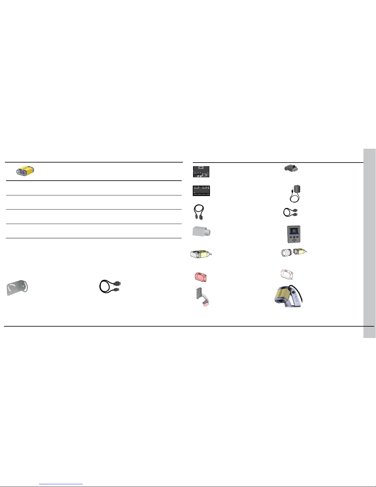
DataMan 100 Accessories
DataMan Basic I/O Module
(DM100-IOBOX-000)
RS-232/USB adapter for
Expansion I/O Module
(DM100-PATCH-000)
Power supply
(DM100-PWR-000)
DataMan Expansion I/O Module
(DM100-1400-000)
RS-232 adapter cable
with power tap
(DM100-RS232-000)
SHD Lens Kit
(read high-density symbols)
(DM100-SHD-000)
C-Mount Lens Adapter
(DM100-CMNT-000)
Direct part mark
illumination kit
(DM100-DMPL-000)
Mounting bracket
(DM100-UBRK-000)
Pivot Mounting Bracket
(DM100-PIVOTM-00)
Harsh Environment Enclosure
(DM100-HENCL-00)
Red lens cover (ESD-safe)
(DM100-RLC-000)
Clear lens cover (ESD-safe)
(DM100-CLC-000)
DataMan 100 Systems
5-meter extension cable*
(DM100-EXTCBL-000)
High-Speed
Part Moving
Applications
1DMax+™ —
Best-In-Class
1-D Reading
IDQuick™ —
High-Speed
2-D Reading
2DMax+™ —
Difcult DPM
Reading
DataMan 100S*
(DMR-100S-xx)
√ √
DataMan 100QL**
(DMR-100QL-xx)
√ √
DataMan 100Q
(DMR-100Q-xx)
√ √ √
DataMan 100X
(DMR-100X-xx)
√ √ √ √
*S model limitations: Maximum decode rate of 5 codes
**QL: 1D / Stacked symbols only
*Note: USB/RS-232 extension connection is possible with the following limitations:
1. The USB connection is shorter than 5m.
2. Serial connection is shorter than 15m.
COGNEX
DO NOT HOT PLUG
DM100 IOBOX
IOB10 200-3001-R1R
RS232 USB24VDC—+OUTPUT
0 1 C 0 1 C
INPUT
COGNEX
CIO-1400
24 VDC
INPUT 7
INPUT 6
INPUT 5
INPUT 4
INPUT 3
INPUT 2
INPUT 1
IN COMMON
COMM OK
SENSOR
MODULE OK
OUT 7
OUT 6
OUT 5
OUT 4
OUT 3
OUT 2
HS OUT 1
HS OUT 0
OUT COMMON
−
+
TRIGGER −
TRIGGER +
RS232 OUT
COGNEX
SensorView Teach
Pendent
(SV-350-001)
Page 4
6 DataMan 100 Quick Reference Guide DataMan 100 Quick Reference Guide 7
Product Overview Mounting
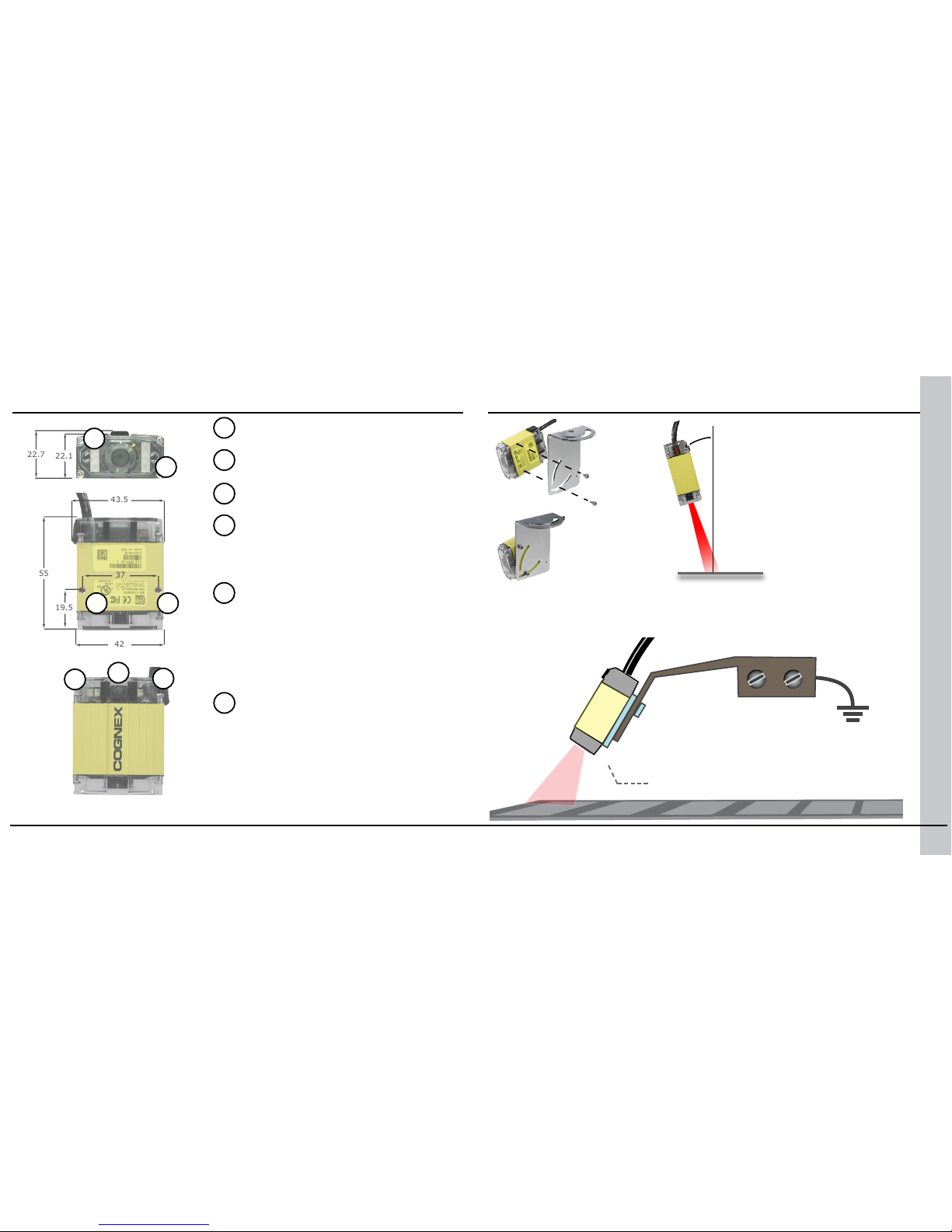
Aiming LED
Mounting holes (M3 x 3.5)
Status LED
• Red: no read
• Green: read
Pushbutton
• Push to read
• Push and hold 3 seconds
to train
• Use Setup tool to program
additional button functions
System LED
• Green: Trained
• Yellow: Untrained
• Steady: System OK
• Slow blink: Connected to Setup
tool
• Fast blink: Data transfer
Illumination LED
Angled Mounting
Mounting the DataMan
100 at a slight angle (15°)
can reduce reections and
improve reader performance.
DataMan 100 Ground Isolator
with non-conductive screws.
Use a DataMan 100 Ground Isolator to prevent mounting your DataMan 100
to conductive material that can provide an electrical path to ground, which
may cause data loss or unreliable operation.
37
19.5
55
43.5
42
37
19.5
55
22.1
22.7
43.5
42
M3 x 5
15°
1
2
3
4
5
6
3
1
2
3
4
5
6
Page 5
8 DataMan 100 Quick Reference Guide DataMan 100 Quick Reference Guide 9
1. Make sure your PC meets the requirements listed in the DataMan Release
Notes.
2. Download the DataMan Setup Tool from http://www.cognex.com/support/
dataman and follow the on-screen steps.
3. Connect the DataMan 100 to your PC following the instructions on pages
14-21.
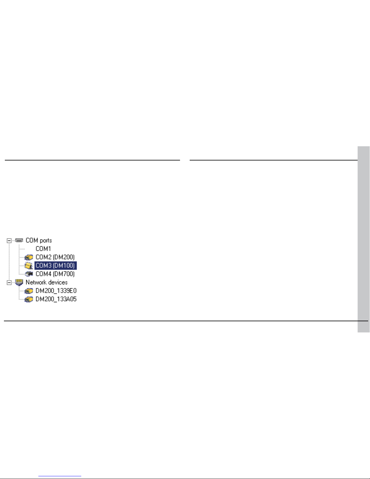
4. Choose Start->Programs->Cognex->DataMan Setup Tool->Setup
Tool to launch the Setup Tool.
5. Click Refresh to update the list of connected devices.
6. Select a COM port that lists a DataMan 100 (DM100) and click Connect.
The DataMan 100 is pre-congured for Manual triggering using the trigger
button and symbology discrimination. To verify that your reader is operational, click on the Results Display pane in the Setup Tool, place a symbol
in front of the reader, and press the black trigger button. The Setup Tool
should display the image and the decoded string.
Troubleshooting
If you are unable to read a valid symbol, try any of the following:
• Scan the correct connection code on page 15 or 17.
• If you are using your PC’s USB to power the DataMan 100, make sure
that your PC’s USB port can supply enough power (2.5W peak). Connect
the DataMan 100 power supply (DM100-PWR-000) to the USB adapter
cable if needed.
• If you are using a direct USB connection, make sure that the USB
adapter cable is connected to the DataMan 100 before you connect the
USB cable to your PC. Connecting or disconnecting the 15-pin plug from
the USB cable while the PC is connected may cause a USB driver crash
on the PC.
• If you are using a USB connection with the Basic I/O module, make
sure that the DataMan 100 is connected to the I/O module before you
connect the I/O module to your PC. Connecting or disconnecting the
15-pin plug from the I/O module while the PC is connected may cause a
USB driver crash on the PC.
Install DataMan Software Reading your First Code
Page 6
10 DataMan 100 Quick Reference Guide DataMan 100 Quick Reference Guide 11
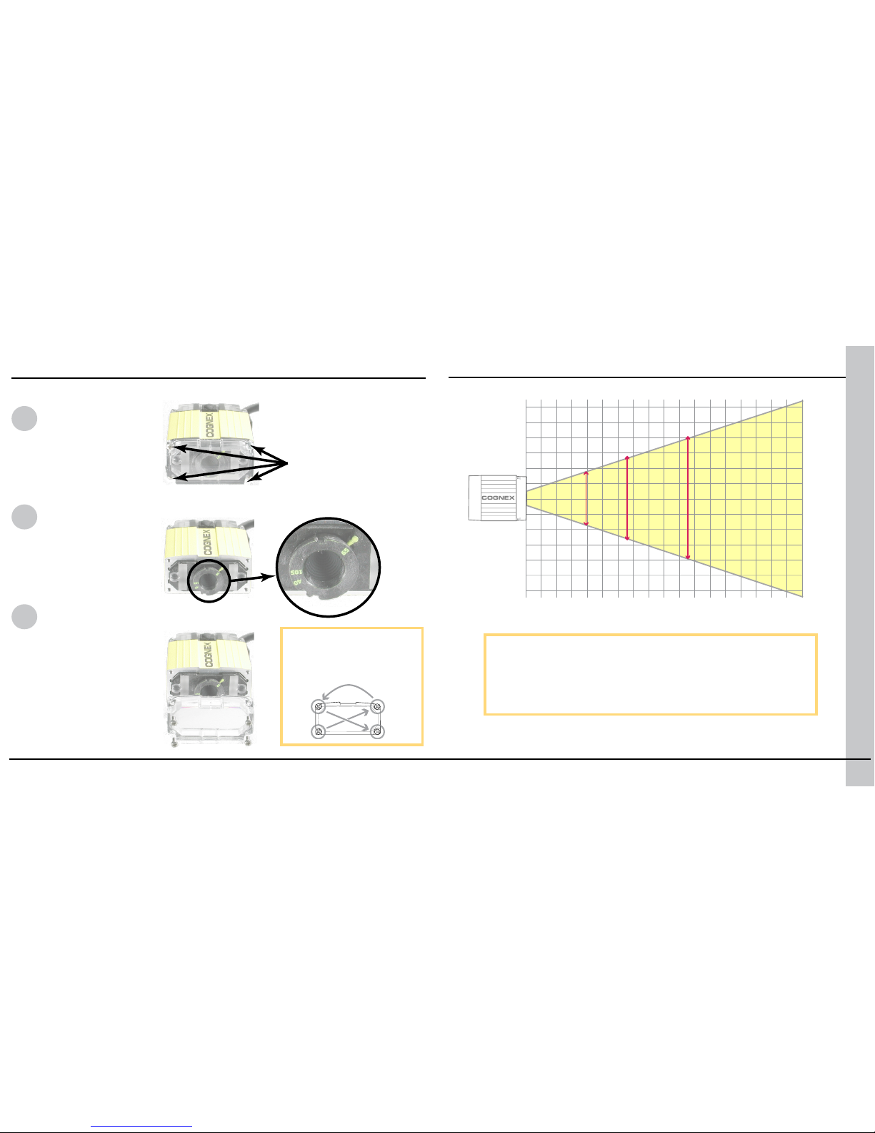
DataMan can operate in one of three distance ranges. To set the focus position:
Field of View
Remove screws
and lens cover.
Set focus
position.
Replace lens cover and
screws.
This chart shows the horizontal eld of view for the
DataMan 100 and DataMan 100-LA at a range of working
distances.
The horizontal and vertical eld of view is shown for
working distances of 40mm, 65mm and 105mm.
Setting the Focus Position
(40 mm)
COGNEX
mm
20
20
20
40
40
40
60
60
60 80 100 120
34 x 22 50 x 32 77 x 49
140 160 180
1
2
3
Tighten screws in order
shown. Maximum torque
for the cover screws is 9
N-cm (0.8 pound-inch).
The size of the holes in
the standard lens cover
is M2x6. For SHD, it is
M2x18. Maximum screw
head diameter is 4 mm.
Page 7
12 DataMan 100 Quick Reference Guide DataMan 100 Quick Reference Guide 13
Reading Distances
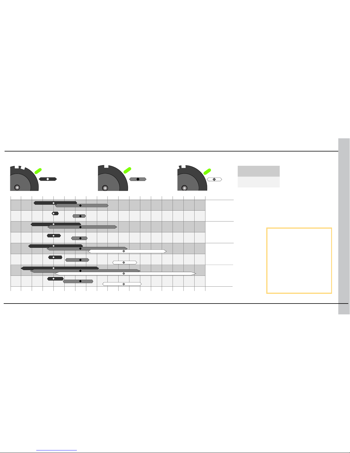
This chart shows the
supported range of reading
distances for four code
sizes (6, 8, 10, and 12 mil)
at each of the three focus
positions (40mm, 65mm,
and 105mm).
The working distances for
both the standard DataMan
100 and the DataMan 100LA (large-aperture) are
shown.
6 mil
8 mil
10 mil
12 mil
DataMan 100
DataMan 100-LA
20mm 40 60 80 100 120 140 160 180
105
40
65
105
40
Page 8
14 DataMan 100 Quick Reference Guide DataMan 100 Quick Reference Guide 15
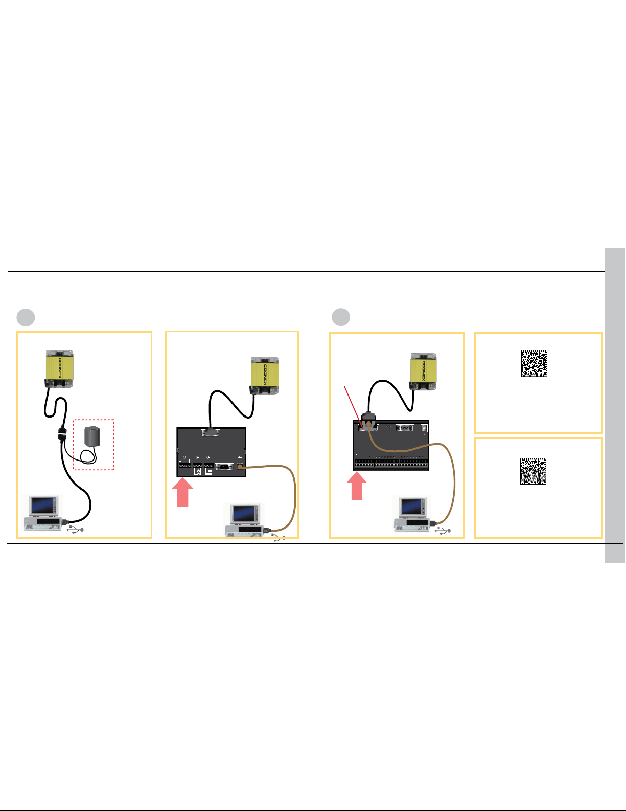
When connected to a PC over USB, the DataMan 100 appears as either a COM
port or as a standard USB keyboard. You control the connection type by scanning the appropriate connection code.
NOTE: DataMan PC software
must be installed for this
connection type!
...connecting directly to the
PC:
USB Serial
USB Keyboard
NOTE: You cannot use
the Setup Tool with this
connection type.
...connecting to the PC
through basic I/O module:
...connecting to the PC through
expanded I/O module:
Make the connection by...
Scan the connection code
24 VDC
24 VDC
USB Connections
COGNEX
CIO-1400
24 VDC
INPUT 7
INPUT 6
INPUT 5
INPUT 4
INPUT 3
INPUT 2
INPUT 1
IN COMMON
COMM OK
SENSOR
MODULE OK
OUT 7
OUT 6
OUT 5
OUT 4
OUT 3
OUT 2
HS OUT 1
HS OUT 0
OUT COMMON
−
+
TRIGGER −
TRIGGER +
RS232 OUT
COGNEX
DO NOT HOT PLUG
DM100 IOBOX
IOB10 200-3001-R1R
RS232 USB24VDC
— +
OUTPUT
0 1 C 0 1 C
INPUT
COGNEX
CIO-1400
24 VDC
INPUT 7
INPUT 6
INPUT 5
INPUT 4
INPUT 3
INPUT 2
INPUT 1
IN COMMON
COMM OK
SENSOR
MODULE OK
OUT 7
OUT 6
OUT 5
OUT 4
OUT 3
OUT 2
HS OUT 1
HS OUT 0
OUT COMMON
−
+
TRIGGER −
TRIGGER +
RS232 OUT
COGNEX
DO NOT HOT PLUG
DM100 IOBOX
IOB10 200-3001-R1R
RS232 USB24VDC
— +
OUTPUT
0 1 C 0 1 C
INPUT
COGNEX
CIO-1400
24 VDC
INPUT 7
INPUT 6
INPUT 5
INPUT 4
INPUT 3
INPUT 2
INPUT 1
IN COMMON
COMM OK
SENSOR
MODULE OK
OUT 7
OUT 6
OUT 5
OUT 4
OUT 3
OUT 2
HS OUT 1
HS OUT 0
OUT COMMON
−
+
TRIGGER −
TRIGGER +
RS232 OUT
DM100-PWR-000
(optional)
DM100-USB-000
DM100-IOBOX-000
DM100-1400-000
DM100-PATCH-000
1
2
Page 9
16 DataMan 100 Quick Reference Guide DataMan 100 Quick Reference Guide 17
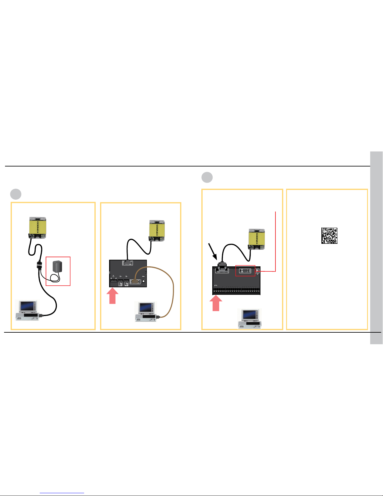
You can connect the DataMan 100 to a PC or other device over a standard
RS-232 serial connection. NOTE: You must supply external power to use this
connection type.
RS-232 Serial
See page 27 for codes to set
baud rate and other RS-232
parameters.
DM100-IOBOX-000
DM100-1400-000
24 VDC
24 VDC
DM100-PATCH-000
...connecting directly to the
PC:
...connecting to the PC
through basic I/O module:
null modem
cable
NOTE: Serial connections from
the extended I/O module to the
PC are only supported for short
(<60 bytes) data transmissions.
You must specify
DM100-1400-000 in the
Discrete I/O Settings pane.
Make the connection by...
Scan the connection code
RS-232 Connections
DM100RS232-000
COGNEX
CIO-1400
24 VDC
INPUT 7
INPUT 6
INPUT 5
INPUT 4
INPUT 3
INPUT 2
INPUT 1
IN COMMON
COMM OK
SENSOR
MODULE OK
OUT 7
OUT 6
OUT 5
OUT 4
OUT 3
OUT 2
HS OUT 1
HS OUT 0
OUT COMMON
−
+
TRIGGER −
TRIGGER +
RS232 OUT
COGNEX
DO NOT HOT PLUG
DM100 IOBOX
IOB10 200-3001-R1R
RS232 USB24VDC
— +
OUTPUT
0 1 C 0 1 C
INPUT
COGNEX
CIO-1400
24 VDC
INPUT 7
INPUT 6
INPUT 5
INPUT 4
INPUT 3
INPUT 2
INPUT 1
IN COMMON
COMM OK
SENSOR
MODULE OK
OUT 7
OUT 6
OUT 5
OUT 4
OUT 3
OUT 2
HS OUT 1
HS OUT 0
OUT COMMON
−
+
TRIGGER −
TRIGGER +
RS232 OUT
COGNEX
DO NOT HOT PLUG
DM100 IOBOX
IOB10 200-3001-R1R
RS232 USB24VDC
— +
OUTPUT
0 1 C 0 1 C
INPUT
IOIOIO
IOIOIO
COGNEX
CIO-1400
24 VDC
INPUT 7
INPUT 6
INPUT 5
INPUT 4
INPUT 3
INPUT 2
INPUT 1
IN COMMON
COMM OK
SENSOR
MODULE OK
OUT 7
OUT 6
OUT 5
OUT 4
OUT 3
OUT 2
HS OUT 1
HS OUT 0
OUT COMMON
−
+
TRIGGER −
TRIGGER +
RS232 OUT
COGNEX
DO NOT HOT PLUG
DM100 IOBOX
IOB10 200-3001-R1R
RS232 USB24VDC
— +
OUTPUT
0 1 C 0 1 C
INPUT
COGNEX
CIO-1400
24 VDC
INPUT 7
INPUT 6
INPUT 5
INPUT 4
INPUT 3
INPUT 2
INPUT 1
IN COMMON
COMM OK
SENSOR
MODULE OK
OUT 7
OUT 6
OUT 5
OUT 4
OUT 3
OUT 2
HS OUT 1
HS OUT 0
OUT COMMON
−
+
TRIGGER −
TRIGGER +
RS232 OUT
COGNEX
DO NOT HOT PLUG
DM100 IOBOX
IOB10 200-3001-R1R
RS232 USB24VDC
— +
OUTPUT
0 1 C 0 1 C
INPUT
COGNEX
CIO-1400
24 VDC
INPUT 7
INPUT 6
INPUT 5
INPUT 4
INPUT 3
INPUT 2
INPUT 1
IN COMMON
COMM OK
SENSOR
MODULE OK
OUT 7
OUT 6
OUT 5
OUT 4
OUT 3
OUT 2
HS OUT 1
HS OUT 0
OUT COMMON
−
+
TRIGGER −
TRIGGER +
RS232 OUT
COGNEX
CIO-1400
24 VDC
INPUT 7
INPUT 6
INPUT 5
INPUT 4
INPUT 3
INPUT 2
INPUT 1
IN COMMON
COMM OK
SENSOR
MODULE OK
OUT 7
OUT 6
OUT 5
OUT 4
OUT 3
OUT 2
HS OUT 1
HS OUT 0
OUT COMMON
−
+
TRIGGER −
TRIGGER +
RS232 OUT
DM100-PWR-000
(required)
1
2
Page 10
18 DataMan 100 Quick Reference Guide DataMan 100 Quick Reference Guide 19
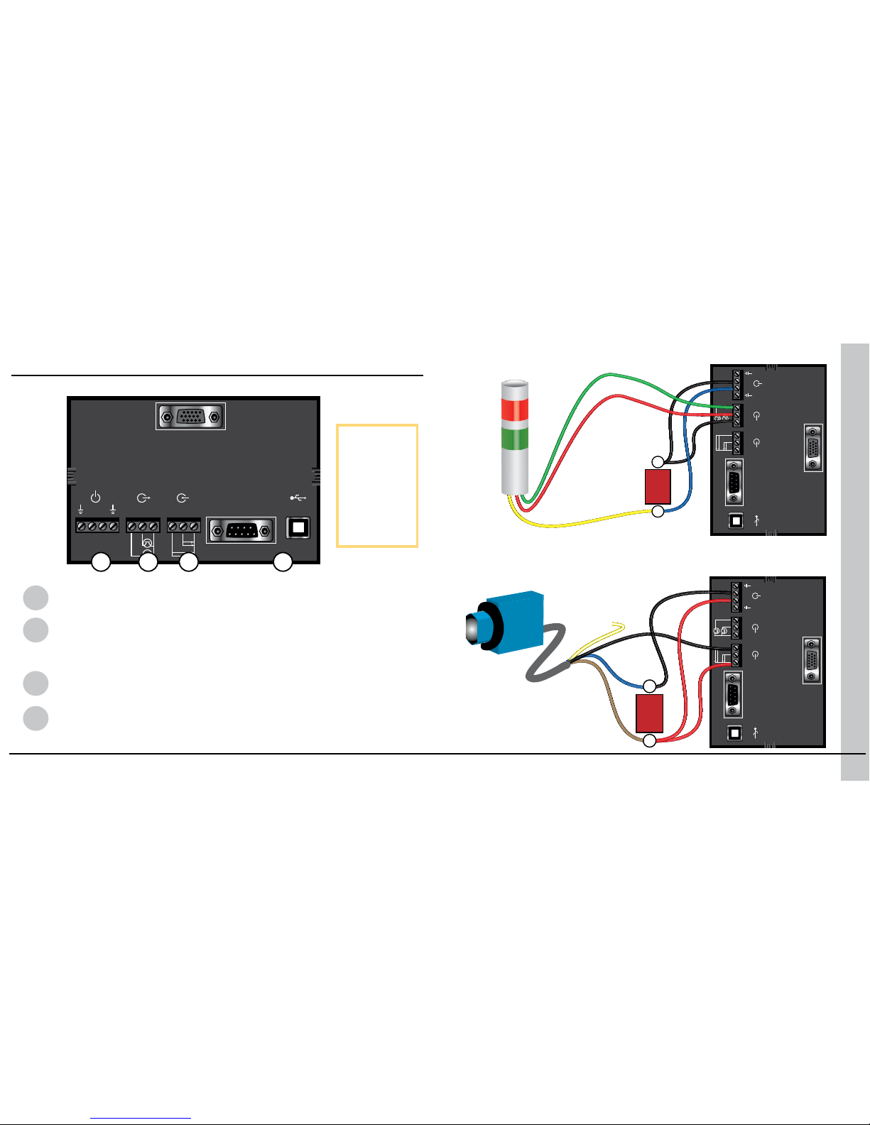
Wiring the Basic I/O Module
1
Power: 5–24 VDC, 2.5W peak. Connect either ground pin to chassis
ground.
2
Discrete Output: Current sink only; must connect logical ground to
common. Outputs are opto-isolated and protected against reverse
polarity. Max current 50 mA @ 24 VDC. Output 1 used for external
illumination control by default.
3
Trigger Input: Opto-isolated, polarity-independent, current source
or sink. Input 0 is dedicated trigger line.
4
RS-232 and USB: If USB connection is detected, USB
communications is automatically selected; otherwise RS-232
connection is used.
NOTE: You
must use a
null modem
cable when
connecting
the Basic I/O
Module to a
PC’s RS-232
serial port.
Output Wiring Example
Input Wiring Example
COGNEX
DO NOT HOT PLUG
DM100 IOBOX
IOB10 200-3001-R1R
RS232 USB24VDC
— +
OUTPUT
0 1 C 0 1 C
INPUT
COGNEX
DO NOT HOT PLUG
DM100 IOBOX
IOB10 200-3001-R1R
RS232 USB24VDC
— +
OUTPUT
0 1 C 0 1 C
INPUT
COGNEX
DO NOT HOT PLUG
DM100 IOBOX
IOB10 200-3001-R1R
RS232 USB24VDC
— +
OUTPUT
0 1 C 0 1 C
INPUT
24V
DC
–
+
24V
DC
–
+
1 2 3 4
Page 11
20 DataMan 100 Quick Reference Guide DataMan 100 Quick Reference Guide 21
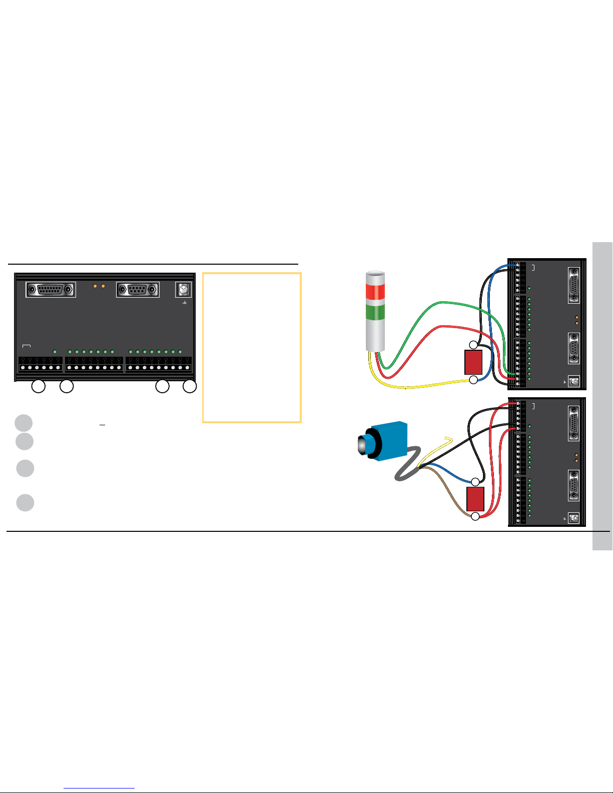
1
Power: 24 VDC + 10%, 4.2W peak.
2
Trigger Input: Opto-isolated, polarity-independent, current source
or sink. Directly wired to DataMan 100 input line 0.
3
Outputs: Six extended output lines congurable using the DataMan
Setup Tool. Current sink only; must connect logical ground to
common. Outputs are opto-isolated and protected against reverse
polarity. Max current 100 mA @ 24 VDC.
4
High-Speed Outputs: Two outputs directly wired to DataMan 100
output lines. Current sink only; must connect logical ground to
common. Outputs are opto-isolated and protected against reverse
polarity. Max current 50 mA @ 24 VDC.
Wiring the Expansion I/O Module
The Trigger+ connector
is wired to Input 0 on the
DataMan 100. The Trigger- connector is wired to
Input Common while the
unlabeled connector next to
Trigger- is wired to Input 1
on the DataMan 100.
The Input 1 through Input 7
connectors are not used.
For limited data transmission over the RS-232 port,
use a straight-through serial
cable.
Output Wiring Example
Input Wiring Example
COGNEX
CIO-1400
24 VDC
INPUT 7
INPUT 6
INPUT 5
INPUT 4
INPUT 3
INPUT 2
INPUT 1
IN COMMON
COMM OK
SENSOR
MODULE OK
OUT 7
OUT 6
OUT 5
OUT 4
OUT 3
OUT 2
HS OUT 1
HS OUT 0
OUT COMMON
−
+
TRIGGER −
TRIGGER +
RS232 OUT
COGNEX
CIO-1400
24 VDC
INPUT 7
INPUT 6
INPUT 5
INPUT 4
INPUT 3
INPUT 2
INPUT 1
IN COMMON
COMM OK
SENSOR
MODULE OK
OUT 7
OUT 6
OUT 5
OUT 4
OUT 3
OUT 2
HS OUT 1
HS OUT 0
OUT COMMON
−
+
TRIGGER −
TRIGGER +
RS232 OUT
24V
DC
–
+
COGNEX
CIO-1400
24 VDC
INPUT 7
INPUT 6
INPUT 5
INPUT 4
INPUT 3
INPUT 2
INPUT 1
IN COMMON
COMM OK
SENSOR
MODULE OK
OUT 7
OUT 6
OUT 5
OUT 4
OUT 3
OUT 2
HS OUT 1
HS OUT 0
OUT COMMON
−
+
TRIGGER −
TRIGGER +
RS232 OUT
24V
DC
–
+
1 2 3 4
Page 12
22 DataMan 100 Quick Reference Guide DataMan 100 Quick Reference Guide 23
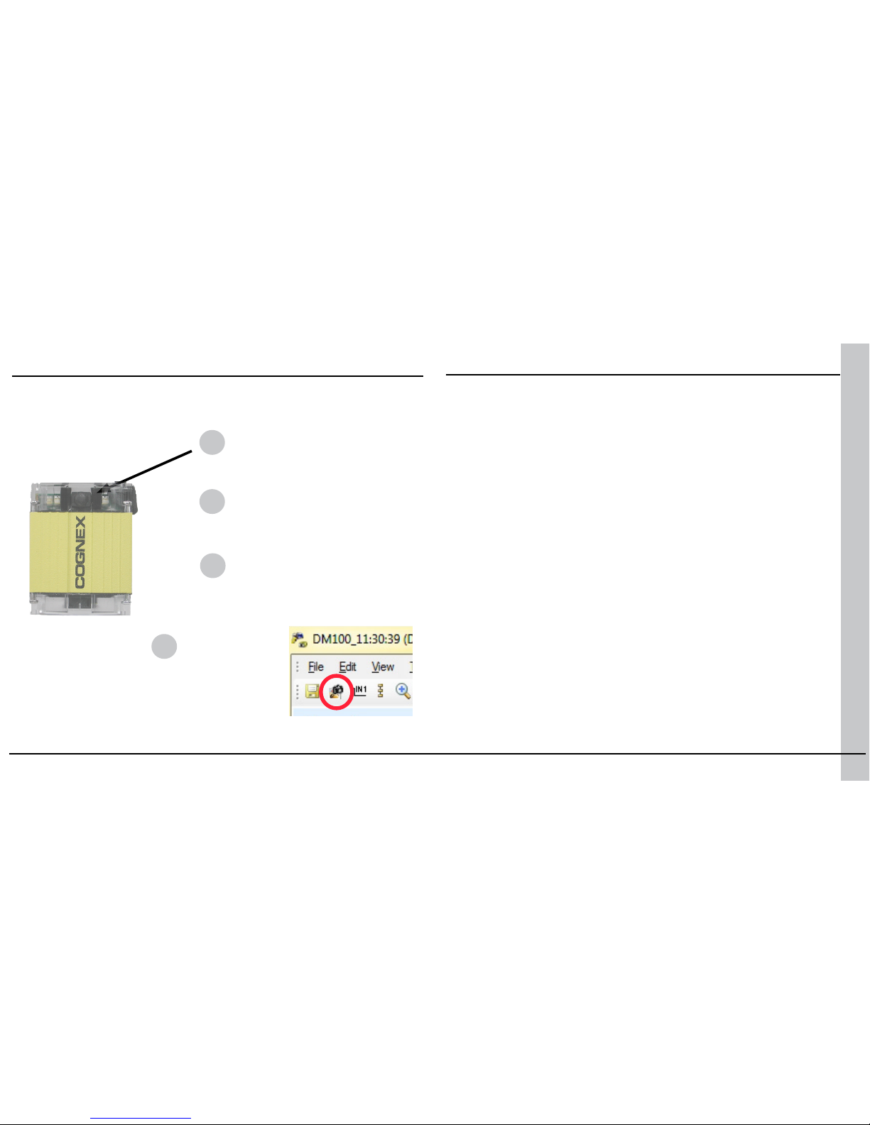
DataMan decodes when you tell it to. You can trigger a read by:
Trigger Modes
Pressing and holding the trigger
button.
Sending a pulse on Input-0 line.
Sending a command on the
serial line. (You must be using
RS-232 or USB communications
type.)
Clicking the
Trigger button or
pressing
<Ctrl>-T in the
Setup tool.
DataMan supports a variety of trigger modes:
• Single: Acquires a single image and attempts to decode any symbol it
contains, or more than one symbol in cases where multicode is enabled.
The reader relies on an external trigger source.
• Presentation: Repeatedly scans for a symbol and decodes it whenever
one is detected. The reader relies on an internal timing mechanism to
acquire images.
• Manual (default): Begins acquiring images when you press the trigger
button on the reader or the discrete trigger input is activated, and
continues acquiring images until a symbol is found and decoded or you
release the button or the discrete trigger input is deactivated.
• Burst: Performs multiple image acquisitions based on an external
trigger and decodes any symbol appearing in a single image or within
a sequence of images, or multiple symbols in a single image or within
a sequence of images when multicode is enabled. You can control the
number of images within each burst and the interval between image
acquisitions.
• Self: Similar to Presentation mode in that the reader perpetually scans
for symbols and decodes them each time one is detected. Unlike
Presentation mode, however, Self mode supports multicode results and a
decode attempt occurs with every image.
• Continuous: Begins acquiring images based on a single external trigger
and continues to acquire images until a symbol is found and decoded, or
until multiple images containing as many codes as specied in multicode
mode are located, or until the trigger is released.
DataMan 100 Trigger Types
1
2
3
4
Page 13
24 DataMan 100 Quick Reference Guide DataMan 100 Quick Reference Guide 25
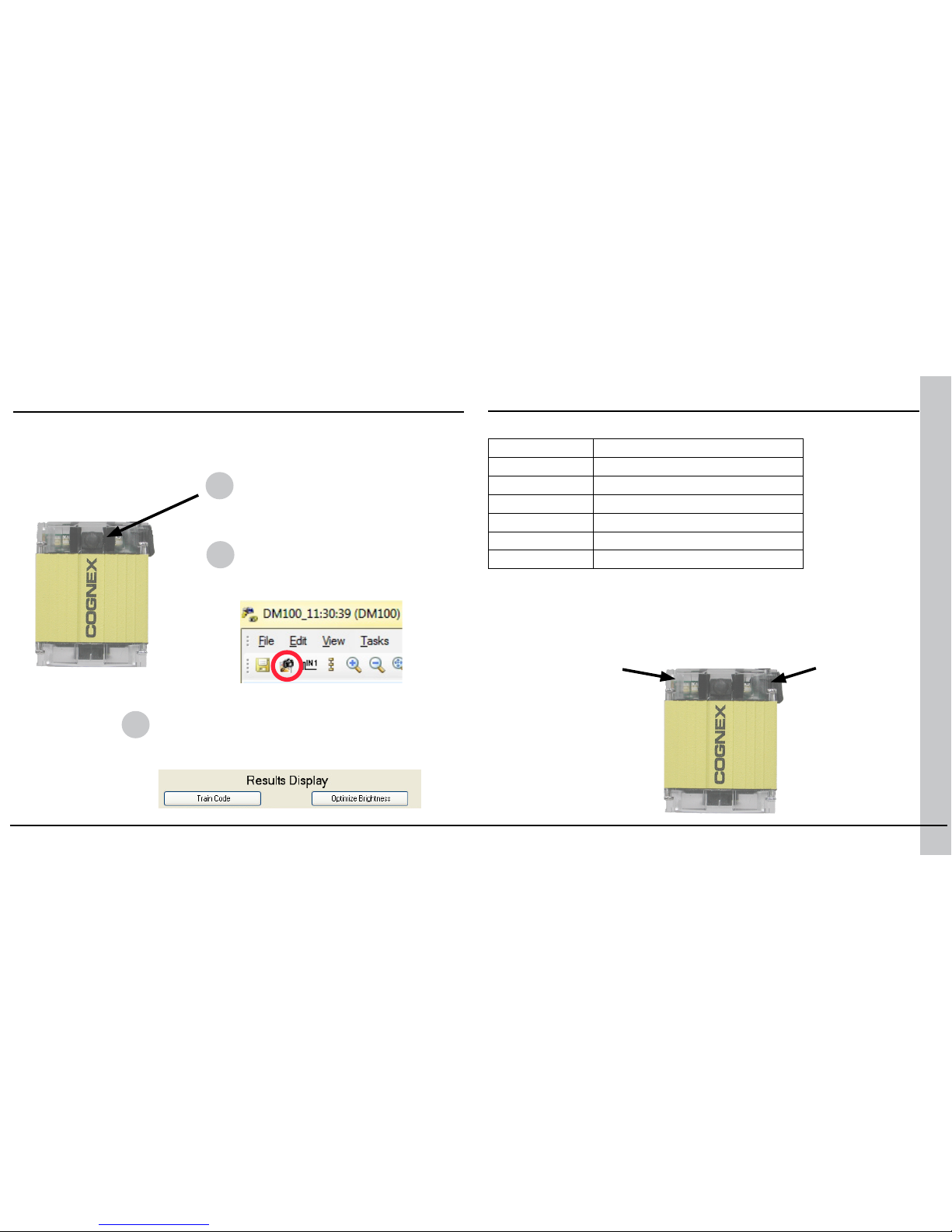
For best performance, you can train DataMan. Train DataMan by placing a code
in front of the reader and doing one of the following:
Training Feedback
DataMan reports the status of the training and brightess optimization
operations using its signalling LEDs:
Press and hold the trigger button for
at least 3 seconds. This trains the
code and optimizes lighting.
In the Display pane of the Setup Tool you
can click the Train Code button to train the
code, and you can click the Optimize Lighting
button to optimize lighting.
Displays steady
green if trained,
steady yellow if
untrained.
A red LED is displayed
during brightness
optimization. When
complete, one, two, or
three green LED ashes
indicates the optimized
exposure time:
• One: > 0.4 msec
• Two: < 0.4 msec
• Three: <= 0.2 msec
Click and hold the trigger button
in the Setup Tool for at least 3
seconds. This trains the code
and optimizes lighting.
Training is supported for the trigger modes shown below:
Trigger Mode Training Supported?
Single Yes
Presentation No
Manual No
Burst Yes
Self Yes
Continuous Yes
Training
Training and Trigger Modes
1
2
3
Page 14
26 DataMan 100 Quick Reference Guide DataMan 100 Quick Reference Guide 27
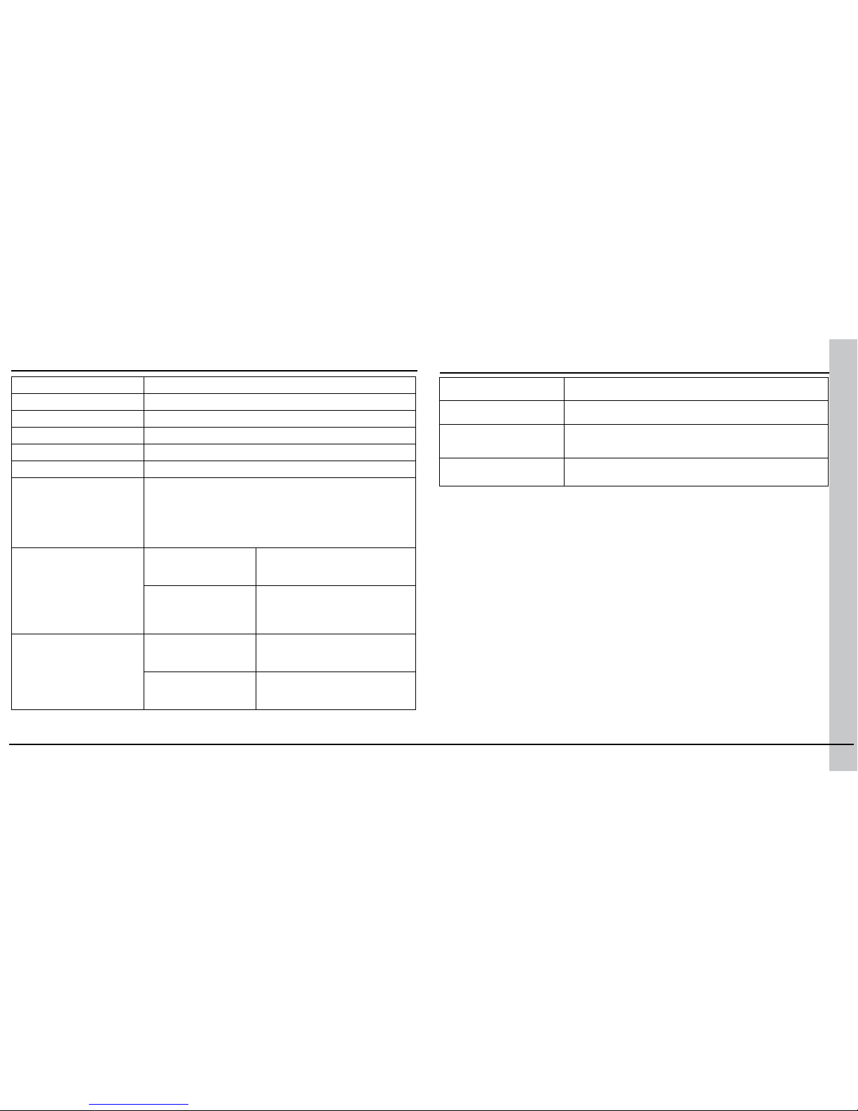
DataMan 100 Specications
Weight
125 g
Operating Temperature
0ºC — 40ºC (32ºF — 104ºF)
Storage Temperature
-10ºC — 60ºC (-14ºF — 140ºF)
Maximum Humidity
95% (non-condensing)
Environmental
IP65
Vibration
EN61373 including IEC 60068-2-6,60068-2-64 6.4, and 60068-2-27
Codes
Data Matrix
TM
(IDMax: ECC 0, 50, 80, 100, 140, and 200; IDQuick: ECC200)
Vericode (optional)
QR Code and microQR Code
UPC/EAN/JAN
Codabar, Interleaved 2 of 5, Code 39, Code 128, and Code 93, Pharma,
Postal, RSS/CS, PDF 417, MicroPDF 417
Discrete I/O
operating limits
HS Output
0,1
I
MAX @ 24 VDC 50 mA
RMAX @ 12 VDC 200 Ω
@ 24 VDC 500 Ω
Input 0 (Trigger)
Input 1
V
IH ±4 — ±25 V
VIL 0 — ±2 V
ITYP @ 12 VDC 3.6 mA
@ 24 VDC 7.5 mA
Power Supply
Requirements
• DataMan 100 and Basic
I/O Module)
5 — 24 VDC
2.5 W maximum
LPS or NEC class 2 power supply
• DataMan 100 and Extended I/O Module
24 VDC ± 10%
4.2 W maximum
LPS or NEC class 2 power supply
DataMan 100 Imager Specications
Specication DataMan 100 Imager
Image Sensor 1/3 inch CMOS
Image Sensor
Properties
4.51mm x 2.88mm (W x H), 6.0μm square pixels
Image Resolution
(Pixels)
752 x 480
Page 15
28 DataMan 100 Quick Reference Guide DataMan 100 Quick Reference Guide 29
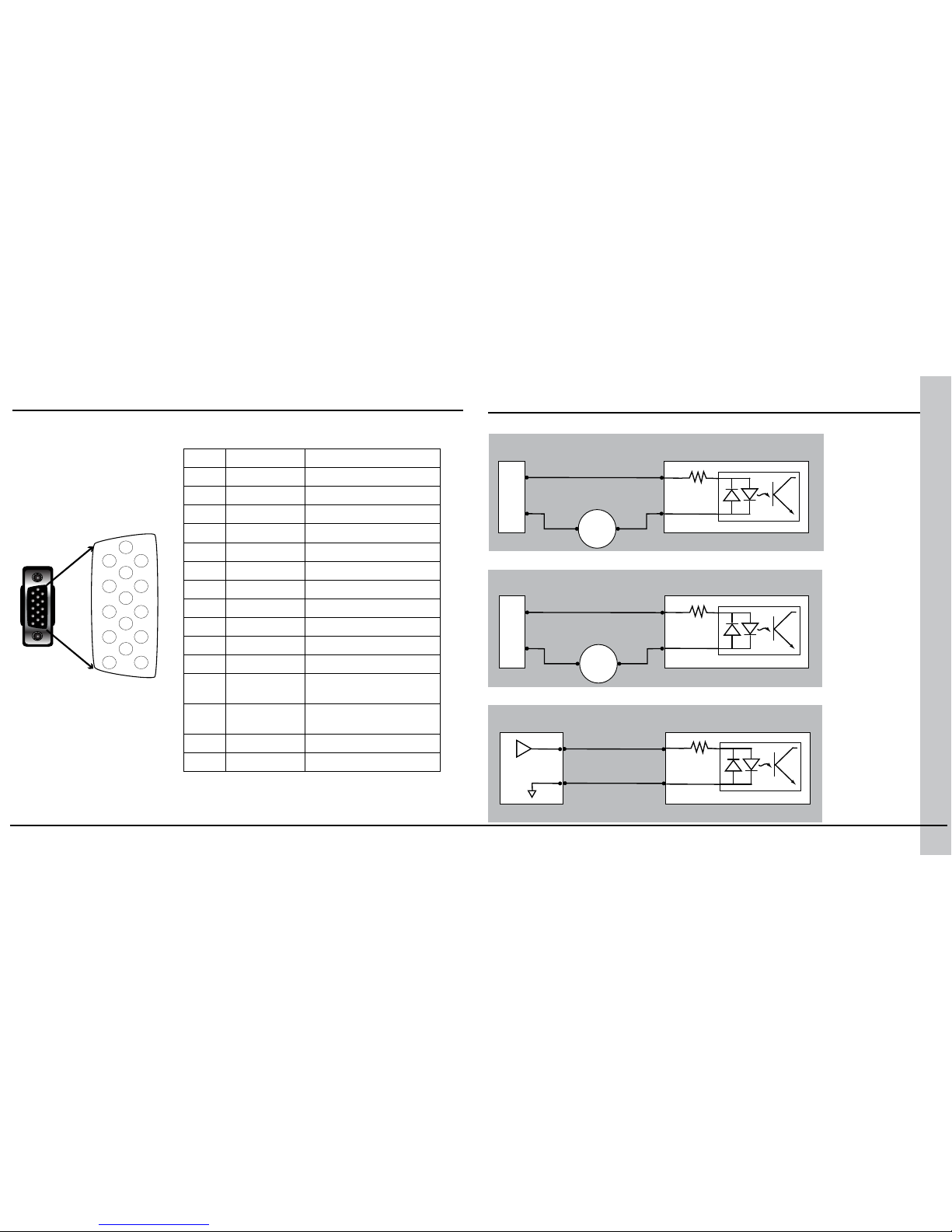
DataMan 100 Cable Pinout
PIN Color Signal
1
Brown Reserved
2
Green TxD (RS-232)
3
Green/Black RxD (RS-232)
4
Red & Red/Black GND
5
Brown/White DC+ (system power, 5-24 VDC)
6
Blue Reserved
7
Blue/White Output-0
8
White Input-0
9
White/Black Input-1
10
Light Blue Reserved
11
Light Blue/Black Output-1
12
Light Blue/
Yellow
Output-Common
13
Light Blue/
Green
Input-Common
14
Yellow Reserved
15
Yellow/Black Reserved
Note: Pin numbers
are shown for cable
connector, not I/O
module.
Note: Colors are of individual wires
within I/O cable.
Digital Input Wiring Diagrams
Current Sink Conguration
Current Source Conguration
Load to a TTL Buffer
1
2
3
4
5
6
7
8
9
10
11
12
13
14
15
+ –
PLC (sourcing) DM100 (sinking)
In 0
COM
OUT
COM
3 KΩ
+ –
PLC (sinking) DM100 (sourcing)
In 0
COM
OUT
COM
3 KΩ
Device (TTL) DM100 (load)
In 0
COM
3 KΩ
Page 16
30 DataMan 100 Quick Reference Guide DataMan 100 Quick Reference Guide 31
DM100
In 0
COM
3 KΩ
Vcc
Device
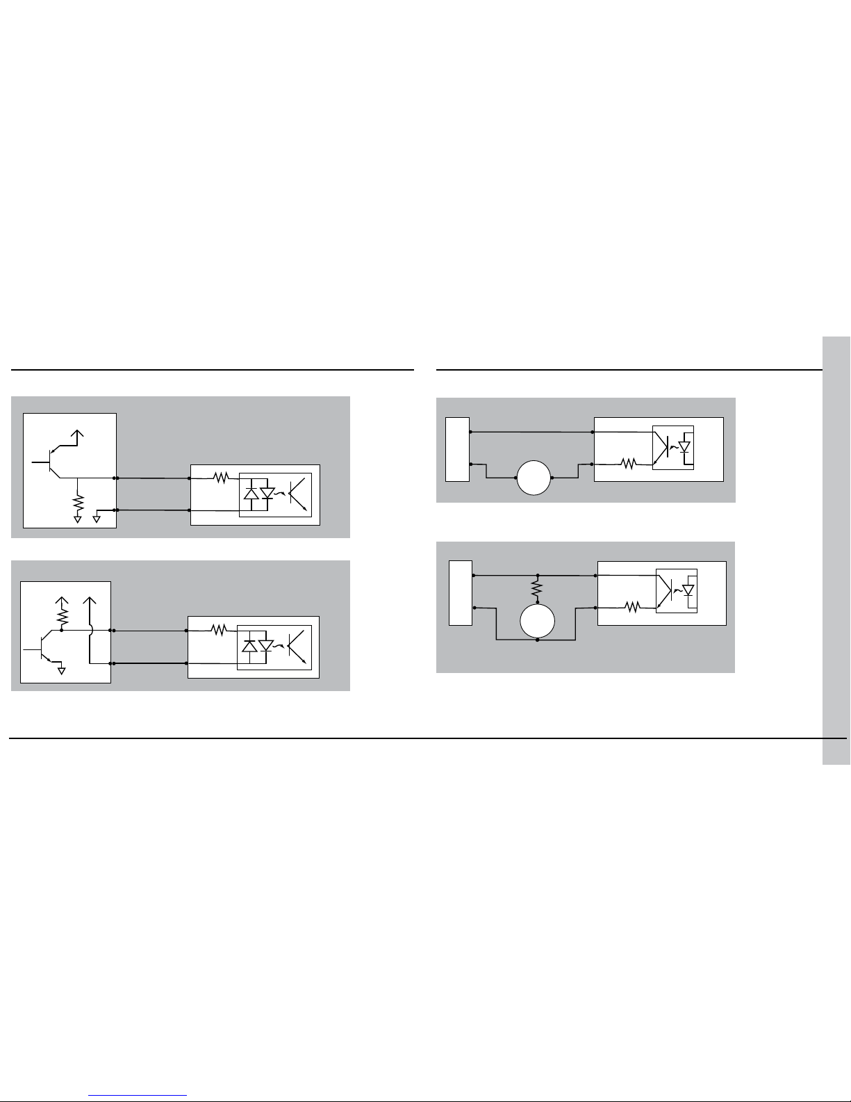
PNP Conguration
NPN Conguration
DM100
In 0
COM
3 KΩ
Vcc
Device
Vcc
+ –
PLC (sourcing) DM100 (sinking)
Out 0/1
COM
10 Ω
IN
COM
Digital Output Wiring Diagrams
Sinking Outputs, Sourcing Inputs
+
–
PLC (sinking) DM100 (sinking)
Out 0/1
R1
COM
IN
COM
10 Ω
Pull-up resistor required (R1):
470 Ω @ 5V
2.2 KΩ @ 12V
4.7 KΩ @ 24V
Sinking Outputs, Sinking Inputs
Digital Input Wiring Diagrams (Continued)
Page 17
32 DataMan 100 Quick Reference Guide DataMan 100 Quick Reference Guide 33
+
–
Device (sinking)
Load
DM100 (sinking)
Out 0/1
R1
COM
10 Ω
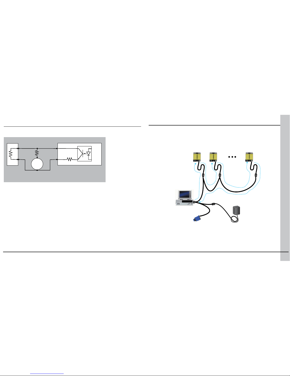
Pull-up resistor required (R1):
470 Ω @ 5V
2.2 KΩ @ 12V
4.7 KΩ @ 24V
Sinking Outputs, Sinking Inputs
You can connect multiple DataMan 100 readers to a single PC (or other
device equipped with a serial port) using a multi-port connection.
A multi-port connection creates a daisy-chain of readers. Each reader
receives serial data from the previous reader and transmits it to the next
reader. When a reader transmits data, it is passed through each of the
readers in the chain between it and the PC.
Because of the large number of possible congurations, Cognex does not
supply cabling for multi-port DataMan 100 connections. Instead, you must
construct your own cable that meets the requirements of your system
conguration.
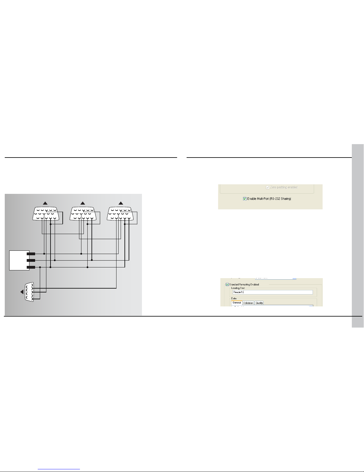
The cable must provide a DB-15 connector for each DataMan 100 and a
DB-9 connector for the PC serial port. Each DB-15 connector must provide
Tx Data, Rx Data, Trigger (Input 0), ground, and DC power. The Tx Data
Multi-Port Connections
Digital Output Wiring Diagrams (Continued)
Page 18
34 DataMan 100 Quick Reference Guide DataMan 100 Quick Reference Guide 35
and Rx Data pins on adjacent connectors must be connected to provide the
multi-port connection.
The following diagram shows how to create a multi-port cable for a
3-reader system. In the example, all the readers share a common trigger.
It is also possible to wire individual triggers for each reader.
You must connect the Setup tool to each DataMan 100 in turn using a USB
connection and set the DataMan for multi-port operation. To congure
a DataMan 100 for multi-port operation, click on the Communication
Settings step and check the Enable Multi-Port (RS-232 Sharing) check
box.
There is no guaranteed delivery order when multiple readers transmit
data using a multi-port connection; read results may arrive at the PC in
any order. You can congure each DataMan 100 reader in a multi-port
connection to add identifying data to each read result. Your PC application
can then determine which reader produced a specic read result.
To do this, click on the Data Formatting step, check the Standard
Formatting Enabled box (for each symbology that you are using), and
enter text in the Leading Text eld. (You can also add trailing text by
entering text in the Trailing Text eld.)
Congure for Multi-Port OperationMulti-Port Connections (Continued)
2
3
5
5432
8
5432
8
5432
8
13
13
13
DataMan 100
2: Tx Data
3: Rx Data
4: GND
5: +DC IN
8: Input 0
13: Input-Common
2: Rx Data
3: Tx Data
5: GND
PC
DataMan 100 DataMan 100
5-24V DC+
TRIG
GND
Page 19
36 DataMan 100 Quick Reference Guide DataMan 100 Quick Reference Guide 37
You can obtain the best results when using multi-port connections by keeping the following usage guidelines in mind as you design your system:
• The maximum cable length between any two DataMan 100 readers or
between the PC and any DataMan reader should be no greater than 15
meters.
• There is no xed limit to the number of DataMan 100 readers that you
can connect to a single PC. Each reader introduces a delay of about 100
msec when it retransmits received serial data. If you have 5 readers,
this means that there will be a 400 msec delay between the time the
rst reader in the chain transmits data and the PC receives it.
• Each DataMan 100 reader must receive a hardware trigger signal on its
Input 0 line. You can wire the input ports to a common trigger signal or
you can provide individual triggers for each reader.
• Each DataMan 100 reader must be individually congured for multi-
port operation, and you must perform this conguration using a USB
connection.
• If any reader in the multi-port chain loses power or becomes
disconnected, then no data from any other reader will be transmitted.
• If a DataMan 100 is transmitting its own read result, it will buffer any
data received from another reader until it has nished its own data
transmission. If a DataMan 100 is transmitting another reader’s data, it
will buffer its own data if it receives a trigger signal while it is processing
the other reader’s data.
• If you use a single power supply for multiple readers, make sure that
the power supply can provide enough power for all of the readers.
Multi-Port Usage Notes
SensorView Teach Pendant Support
A SensorView Teach Pendant is a panel-mounted control system that lets
you train symbologies and view images, decoded data and statistics from a
DataMan 100 reader.
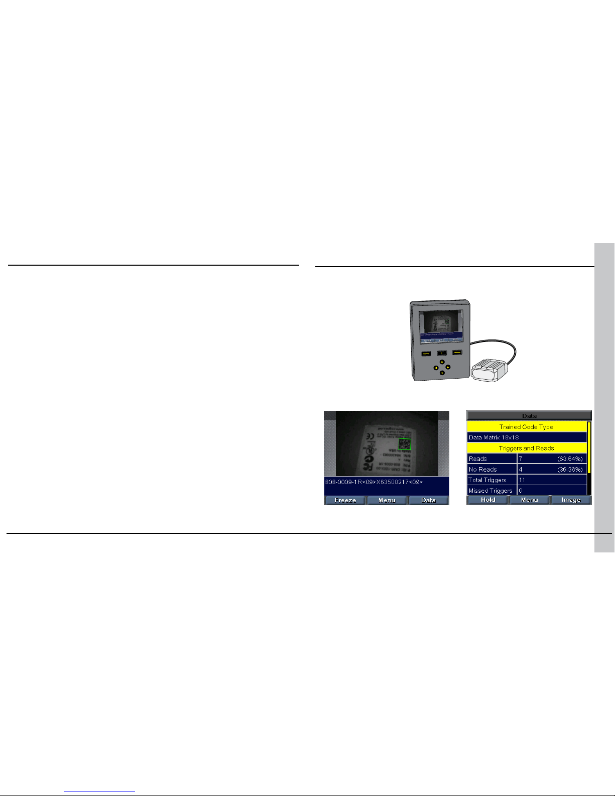
When connected to a DataMan 100, a SensorView Teach Pendant shows you
acquired images and decoded data.
COGNEX
COGNEX
COGNEX
COGNEX
The SensorView Teach Pendant User’s Guide describes how to connect a
SensorView Teach Pendant to your DataMan 100.
Page 20
38 DataMan 100 Quick Reference Guide DataMan 100 Quick Reference Guide 39
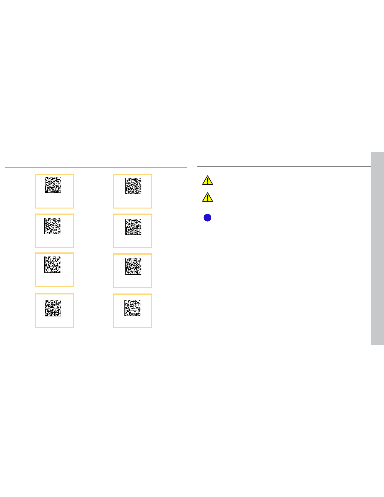
8-1-even
8-1-none
115,200 Baud
8-1-odd
RS-232 Parameter Codes
9600 Baud
19,200 Baud
38,400 Baud
57,600 Baud
Warnings and Notices
CAUTION: This device requires the use of an LPS or NEC class 2 power
supply.
CAUTION: Do not connect or disconnect this device from the I/O module
or 15-pin USB adapter cable while the I/O module or adapter cable is connected to a PC .
NOTE: For product support, contact http://support.cognex.com
i
Page 21
40 DataMan 100 Quick Reference Guide DataMan 100 Quick Reference Guide 41
with the instructions, may cause harmful interference to radio communications. Operation of this
equipment in a residential area is likely to cause
harmful interference, in which case the user will
be required to correct the interference at personal
expense.
Canadian Compliance
This Class A digital apparatus complies with
Canadian ICES-003.
Cet appareil numérique de la classe A est conforme à la norme NMB-003 du Canada.
C-Tick Statement
Conforms to AS/NZS CISPR 22/ EN 55022 for Class
A Equipment.
European Compliance
The CE mark on the product indicates that the
system has been tested to and conforms with
the provisions noted within the 2004/108/EC
Electromagnetic Compatibility Directive and the
2006/95/EC Low Voltage Directive.
For further information please contact:
Cognex Corporation
One Vision Drive
Natick, MA 01760
USA
The DataMan 100 series meets or exceeds the requirements of all applicable standards organizations
for safe operation. However, as with any electrical
equipment, the best way to ensure safe operation is
to operate them according to the agency guidelines
that follow. Please read these guidelines carefully
before using your device.
Regulator Specication
USA FCC 47 CFR Part 15 Subpart B,
Class A
Canada ICES-003
European
Community
EN55022 (CISPR 22) Class A
EN55024:1998 +A1:2001 +A2:
2003
EN60950
Australia C-TICK, AS/NZS CISPR 22 / EN
55022 for Class A Equipment
Japan J55022, Class A
FCC Class A Compliance Statement
This equipment has been tested and found to
comply with the limits for a Class A digital device,
pursuant to Part 15 of the FCC rules. These limits are
designed to provide reasonable protection against
harmful interference when the equipment is operated in a commercial environment. This equipment
generates, uses, and can radiate radio frequency
energy and, if not installed and used in accordance
Compliance Statements
Cognex Corporation shall not be liable for use of our
product with equipment (i.e., power supplies, personal
computers, etc.) that is not CE marked and does not
comply with the Low Voltage Directive.
UL and cUL Statement
UL and cUL listed: UL60950-1 1st ed. and CSA C22.2
No.60950-1 1st ed.
Certied to CB scheme IEC 60950-1:2001 1
st
ed.
For European Community Users
Cognex complies with Directive 2002/96/EC OF THE
EUROPEAN PARLIAMENT AND OF THE COUNCIL of 27
January 2003 on waste electrical and electronic equipment (WEEE).
This product has required the extraction and use of
natural resources for its production. It may contain
hazardous substances that could impact health and
the environment, if not properly disposed.
In order to avoid the dissemination of those substances in our environment and to diminish the pressure
on the natural resources, we encourage you to use the
appropriate take-back systems for product disposal.
Those systems will reuse or recycle most of the materials of the product you are disposing in a sound way.
The crossed out wheeled bin symbol informs
you that the product should not be disposed of
along with municipal waste and invites you to
use the appropriate separate take-back systems
for product disposal.
If you need more information on the collection,
reuse, and recycling systems, please contact your
local or regional waste administration.
You may also contact your supplier for more
information on the environmental performance
of this product.
Page 22
Copyright © 2015 Cognex Corporation All Rights Reserved. This document may not be
copied in whole or in part, nor transferred to any other media or language, without the
written permission of Cognex Corporation. The hardware and portions of the software
described in this document may be covered by one or more of the U.S. patents listed
on the Cognex web site http://www.cognex.com/patents.asp. Other U.S. and foreign
patents are pending. Cognex, the Cognex logo, and DataMan are trademarks, or
registered trademarks, of Cognex Corporation.
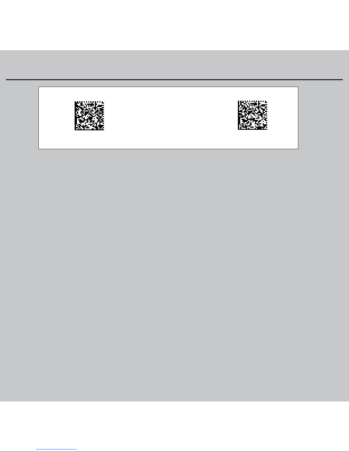
Reset Scanner to
Factory Defaults
Reboot Scanner
Reader Control Codes
 Loading...