

Page 1

0344
UPC 200-B
Neuromodulationssystem • Sistema de neuromodulación •
Système de neuromodulation percutanée • Sistema di neuromodulazione
• Neuromodulatiesysteem • Sistema deneuromodulação •
Nöromodülasyon Sistemi
URGENT® PC STIMULATOR
Instructions for Use .................................................3
URGENT® PC-STIMULATOR
Gebrauchsanweisung ...................................................................... 22
ESTIMULADOR URGENT® PC
Instrucciones de uso ........................................................................ 44
STIMULATEUR URGENT® PC
Mode d’emploi ................................................................................. 64
STIMOLATORE URGENT® PC
Istruzioni per l’uso ........................................................................... 84
URGENT® PC-STIMULATOR
Instructies voor gebruik ................................................................. 104
ESTIMULADOR URGENT® PC
Instruções de utilização ................................................................. 126
URGENT® PC STIMÜLATÖRÜ
Kullanım Kılavuzu .......................................................................... 146
Page 2
English
3
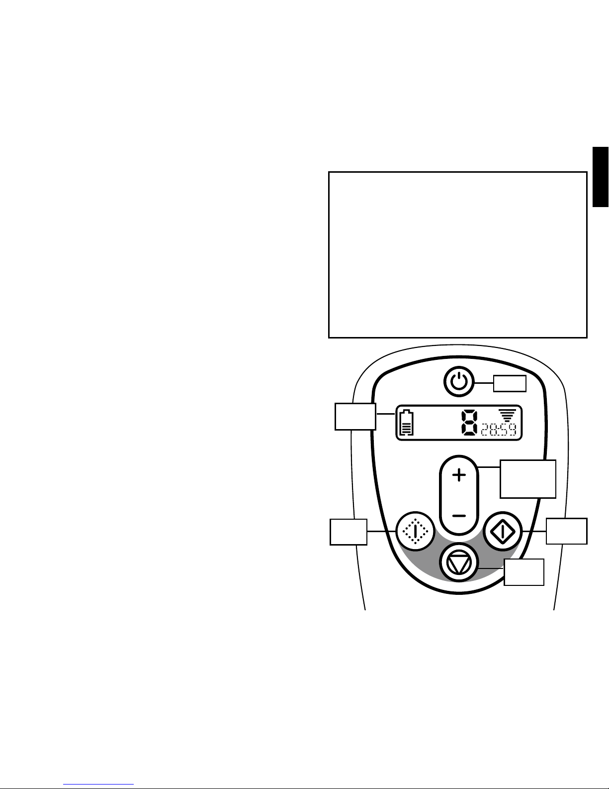
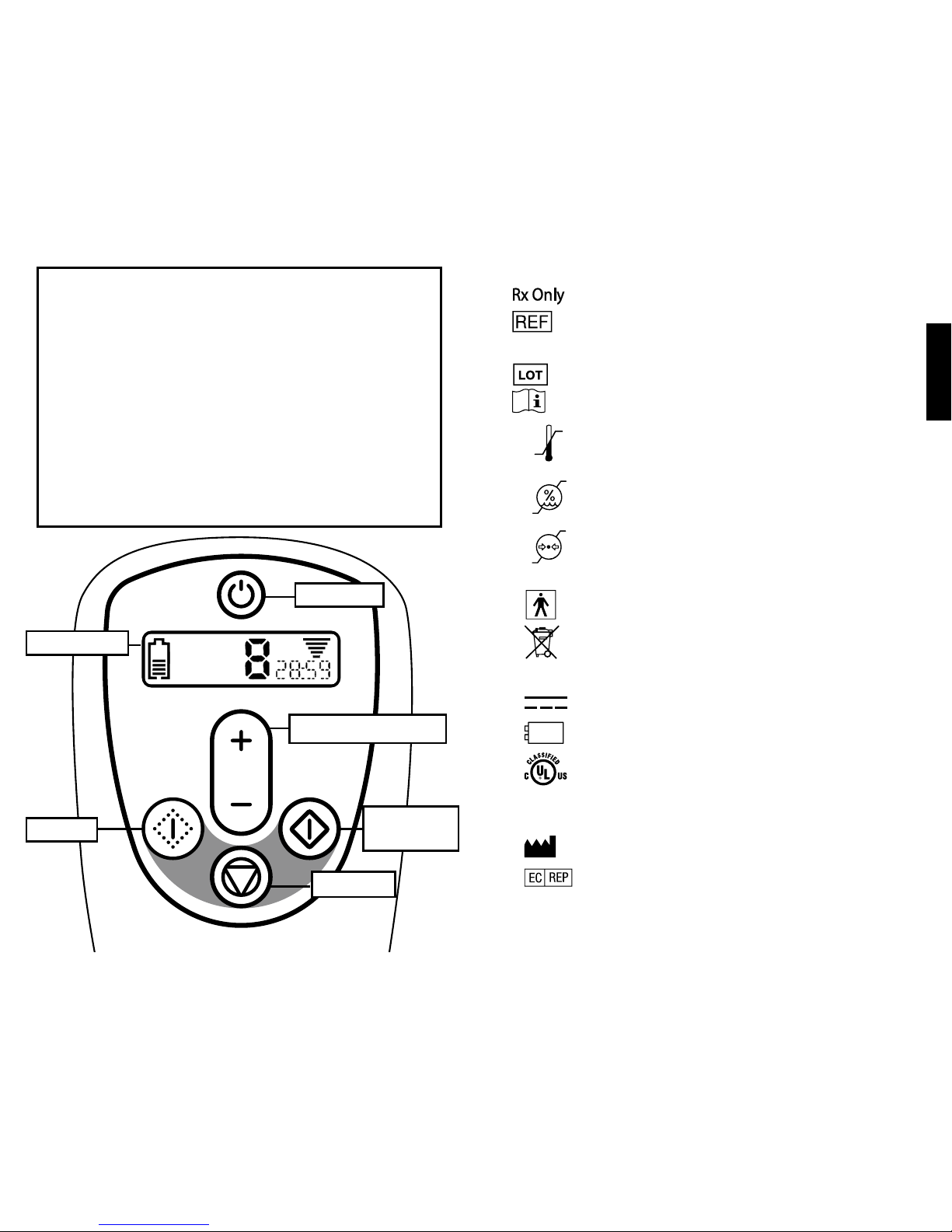
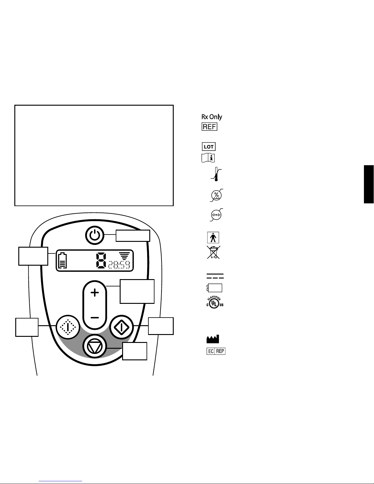
Power
Current
Adjustment
button
Test
button
Stop
button
Therapy
button
Status
Screen
CONTENTS:
Description of Symbols ........................................................................ 4
Indications for Use ............................................................................... 4
Product Description ............................................................................. 5
Contraindications for Use .................................................................... 5
Warnings..............................................................................................6
Precautions .......................................................................................... 7
Product Specications ......................................................................... 8
Instructions for Use ............................................................................ 12
Electromagnetic Compatibility ........................................................... 17
Warranty ............................................................................................ 20
Page 3
English
4
5
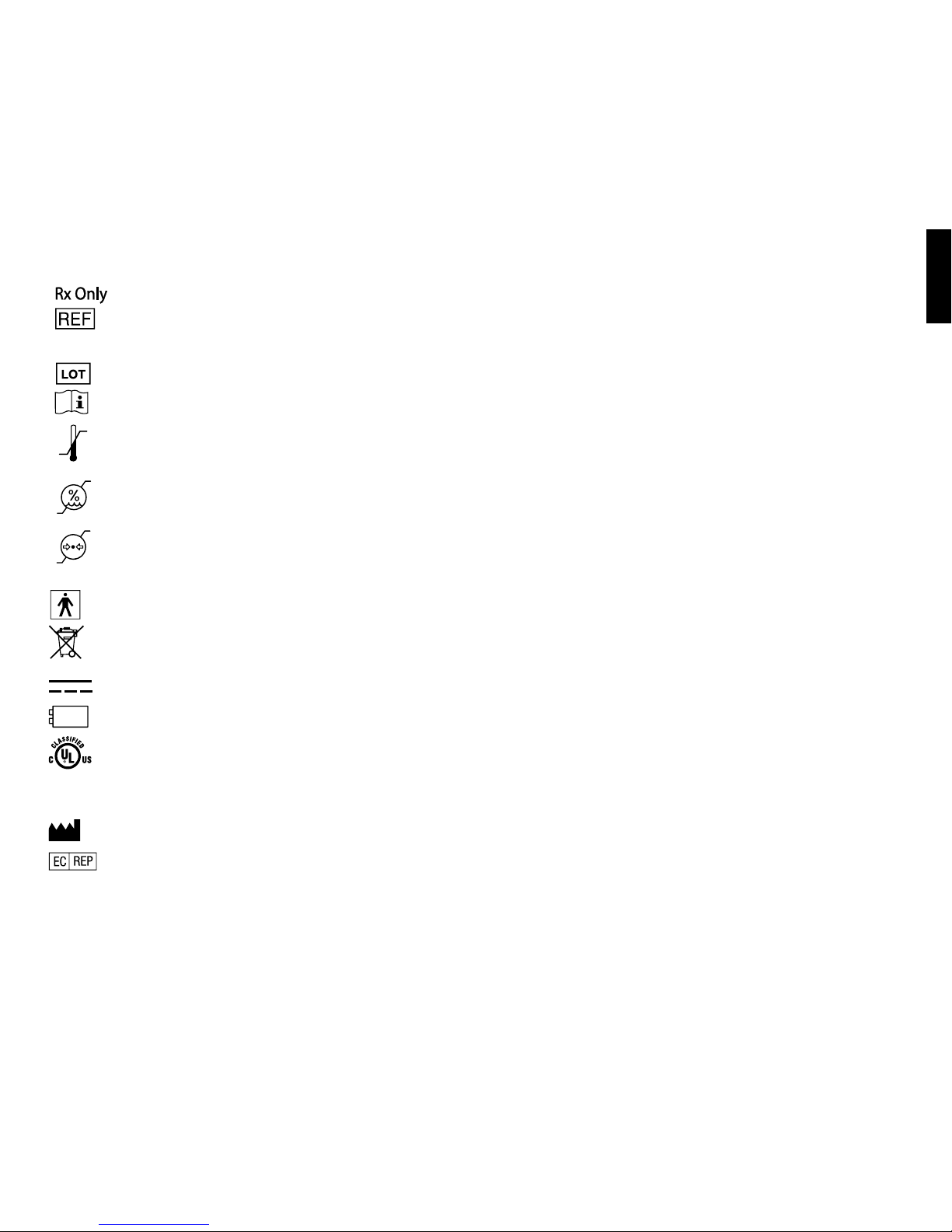
DESCRIPTION OF SYMBOLS
Prescription Use Only
Product Reference Number
Serial Number
Lot Number
Consult Instructions for Use
Temperature limitation of -20°C (-4°F) to 60°C (140°F)
Relative humidity of 20% to 80%, non-condensing
Atmospheric pressure of 500 hPa to 1060 hPa
Type BF Applied Part
Waste electrical and electronic equipment (WEEE)
should not be disposed as unsorted municipal waste;
WEEE should be collected separately.
Direct Current
9V Alkaline Battery
Classified by Underwriters Laboratories Medical
Equipment With Respect to Electric Shock, Fire, and
Mechanical Hazards Only. In accordance with UL 60601-1,
CAN/CSA C22.2 No. 601.1, EN 60601-1, IEC 60601-1,
and IEC 60601-2-10.
Manufacturer
Authorized Representative in European Community
INDICATIONS FOR USE
The Urgent® PC Neuromodulation System is intended to treat patients
suffering from urinary urgency, urinary frequency, and urge incontinence.
The Urgent PC is also indicated for the treatment of fecal incontinence.
PRODUCT DESCRIPTION
The Urgent PC Neuromodulation System is a minimally invasive
neuromodulation system designed to deliver retrograde access to the
sacral nerve through percutaneous electrical stimulation of the tibial
nerve. The method of treatment is referred to as Percutaneous Tibial
Nerve Stimulation (PTNS).
The Urgent PC Neuromodulation System is a combination of the Urgent
PC Stimulator (Stimulator) and the Urgent PC Lead Set (Lead Set). The
Stimulator and Lead Set are sold separately.
The Stimulator is a battery powered, external pulse generator and
is designed, constructed, and manufactured for multiple use. The
Stimulator is to be used only in conjunction with the single-use Lead
Set. The Lead Set (comprised of the Lead Wire, Needle Electrode,
and Alcohol Pad) transfers the electrical current from the Stimulator to
the tibial nerve via the Needle Electrode. The only components of the
Urgent PC Neuromodulation System provided sterile are the Needle
Electrodes.
CONTRAINDICATIONS FOR USE
1. In order for treatment to be effective and to avoid any possible
problems or complications, the device is contraindicated for use on
patients who have the following history or conditions:
» Patients with pacemakers or implantable defibrillators
» Patients prone to excessive bleeding
» Patients with nerve damage that could impact either
percutaneous tibial nerve or pelvic floor function
2. The Stimulator is not intended for intra-cardiac or trans-thoracic use.
3. Do not use the Stimulator on patients who are pregnant or planning
to become pregnant while using this product.
4. Concurrent use of medical monitoring equipment during stimulation
is not recommended.
5. This device is not suitable for use in the presence of a ammable
anesthetic mixture with air or with oxygen or nitrous oxide.
SN
-20°C
60°C
20%
80%
500
hPa
1060
hPa
Page 4

English
6
7
WARNINGS
1. This Instructions for Use is NOT a comprehensive reference to
therapeutic techniques for the treatment indications noted for the
Urgent PC.
2. Users should be familiar with appropriate application and techniques
involved in the use of the Stimulator and the Lead Set.
3. Do not use the Stimulator in or around water.
4. Do not use the Stimulator or Lead Set if the skin in the area of use
is inamed, infected, or otherwise compromised. Monitor patients
during treatment for pain or skin irritation/inammation. Discontinue
use of the Stimulator if the patient complains about these symptoms
or any other discomfort.
5. Do not open battery cover while Stimulator is powered on or
connected to the patient.
6. Patients should not spend more than 30 minutes in Therapy mode
during a single treatment session.
7. The patient should remain comfortably seated, or in a supine
position, for the duration of the treatment. The patient should not rise
or walk until the treatment is complete, as mobility during treatment
has not been assessed.
8. Do not use any Lead Set component (Lead Wire, Needle Electrode
or Alcohol Pad) if the component is damaged.
9. Do not use the Needle Electrode or the Alcohol Pad if the packaging
for either component has been opened or damaged.
10. Do not reuse the single-use Needle Electrode, Surface Electrode, or
Lead Wire.
11. Dispose of used Lead Set components in a bio-hazardous material
disposal container.
12. Remove battery if equipment is not likely to be used for some time.
13. Simultaneous connection of a patient to high frequency surgical
equipment may result in burns at the site of the Stimulator electrodes
and possible damage to the Stimulator.
14. Device operation in close proximity (e.g., 1 meter) to short wave
or microwave therapy equipment may produce instability in the
Stimulator output.
15. The application of the electrodes near the thorax may increase the
risk of cardiac brillation.
16. Do not apply stimulation across or through the head, directly on the
eyes, covering the mouth, on the front of the neck (especially the
carotid sinus), chest, upper back or crossing over the heart.
17. The Stimulator has electric shock protection, Type “Internally
Powered Equipment.”
18. The Stimulator enclosure is type IPX0 and does not protect against
the ingress of water.
19. Unauthorized modication of this equipment may cause injury to
either the patient or the device operator.
PRECAUTIONS
1. Prior to using the Urgent® PC Neuromodulation System, read and
understand all instructions in the Urgent PC Stimulator Instructions for
Use and Urgent PC Lead Set Instructions for Use.
2. Caution should be used for patients with suspected or diagnosed
heart problems, especially those relating to the pacing or electrical
functioning of the heart.
3. The following are potential health risks associated with this type of
device and therapy:
» Discomfort and pain (including throbbing pain) at, or near, the
stimulation site, including the patient’s lower leg and foot
» Bleeding at the needle site
» Redness/inflammation at, or near, the stimulation site
» Potential for peripheral nerve damage
» Numbness of toes
» Stomach ache
4. Medical electrical equipment needs special precautions regarding
electromagnetic compatibility (EMC) and needs to be installed
and placed into service according to EMC guidelines provided
(see page 18 for more information).
a. Portable and mobile radio frequency (RF) communications
equipment can affect medical electrical equipment.
b. The end user of this product should assure it is used in an
appropriate environment.
i. Portable and mobile RF Communications equipment
(i.e., cell phones) should not be used at close distances.
ii. Power frequency magnetic elds should be at levels
characteristic of a typical commercial, hospital or clinic
environment.
Page 5
English
8
9
PRODUCT SPECIFICATIONS
Urgent PC Stimulator
1. Design Features:
» Lightweight, ergonomic, handheld design
» Electronic touch pad controls
» Raised and embossed buttons to provide tactile feedback
» LCD status screen to provide operational status
» One-way fit connection site for Lead Set
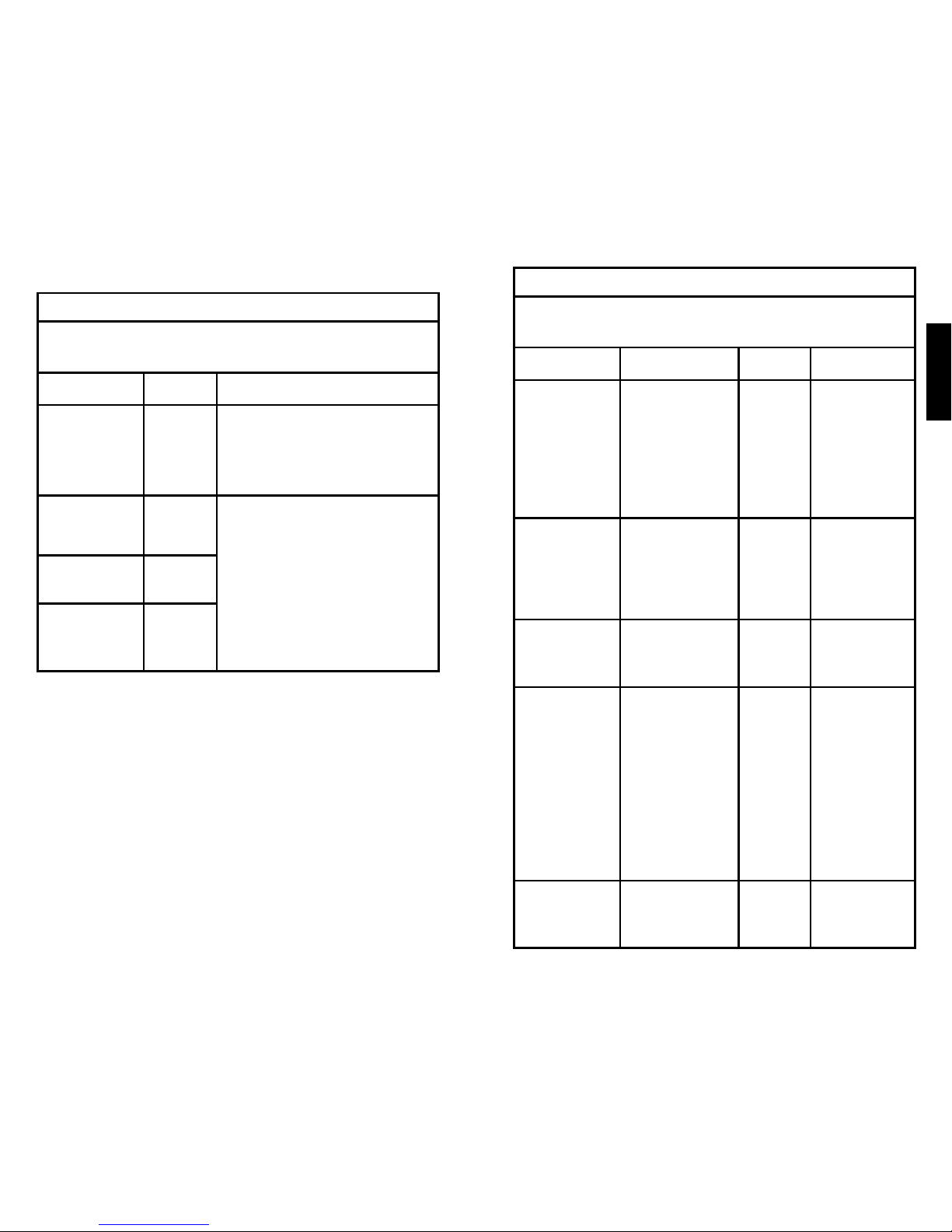
2. Electrical Current Settings:
» Pulse characteristics:
◦ Fixed pulse frequency of 20 Hz
◦ Pulse width of 200 µseconds
◦ Square waveform
» Resistance of 500-4000 Ohms.
Current
Setting
Current
(in mA)
0 0
1 0.15
2 0.5
3 1.0
4 1.5
5 2.0
6 2.5
7 3.0
8 3.5
9 4.0
Current
Setting
Current
(in mA)
10 4.5
11 5.0
12 5.5
13 6.0
14 6.5
15 7.0
16 7.5
17 8.0
18 8.5
19 9.0
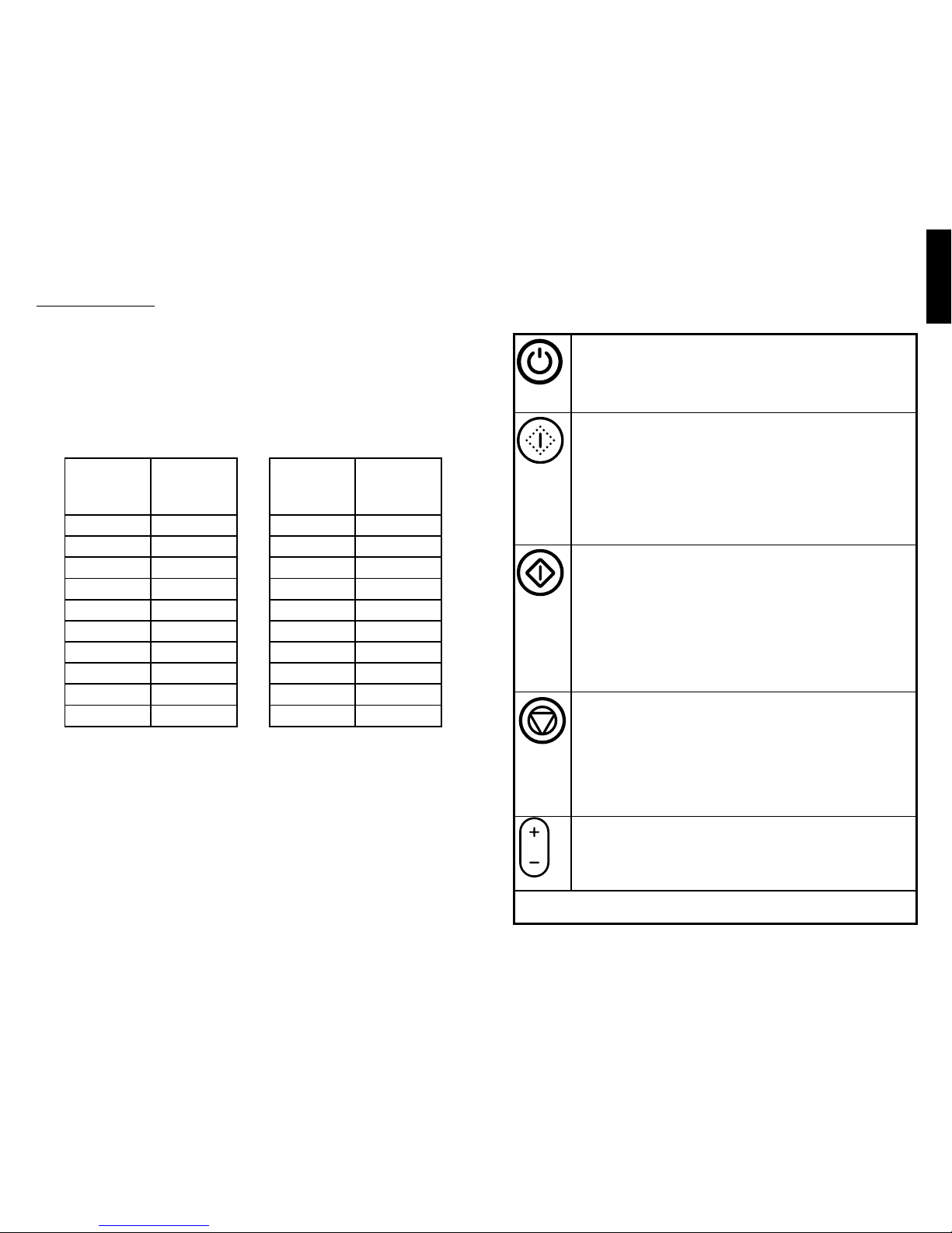
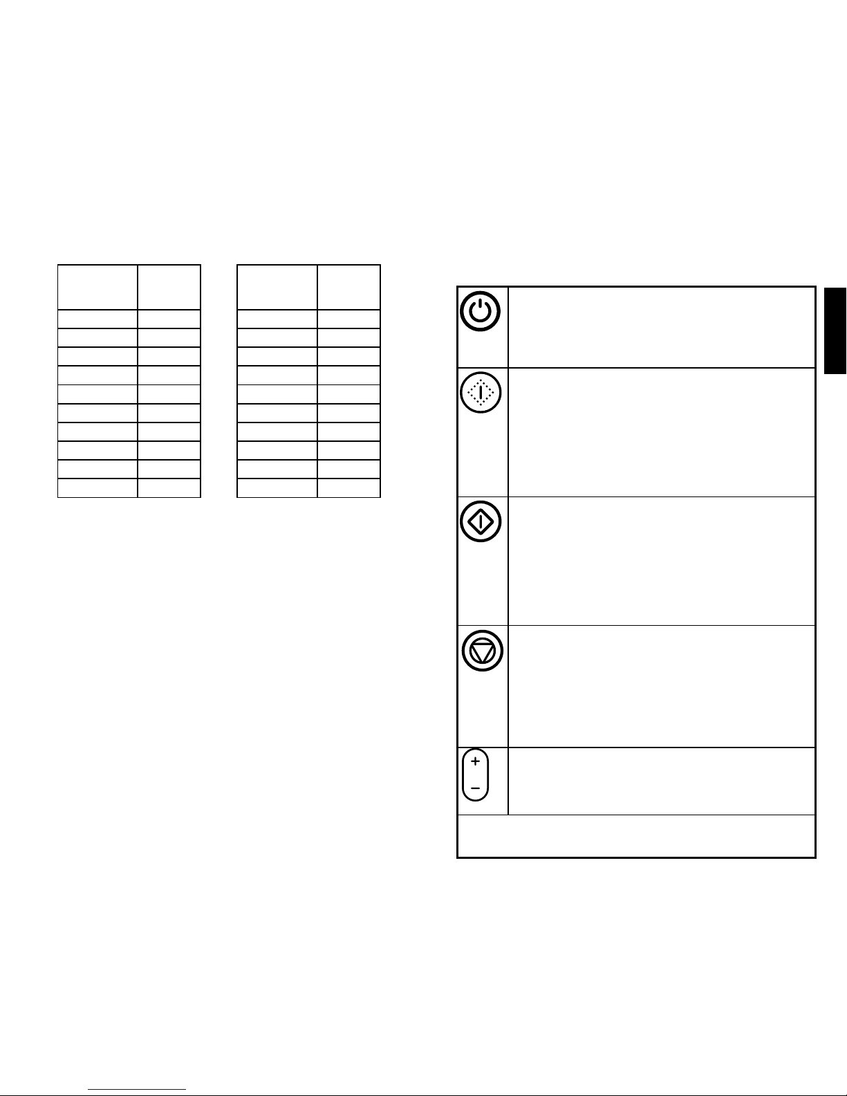
Button Controls
The Stimulator is controlled by raised buttons on the device. These
buttons are:
Power button – turns power on and off
Note: To turn the power on or off, the user is required to depress
the Power button for approximately 2 seconds. This is designed
to protect the Stimulator from inadvertent status changes.
Test (yellow) button – begins Test mode
Upon entering Test mode, the default current setting will be 0
(0mA). At the completion of the Test mode, the nal current
setting shall be the baseline setting in Therapy mode.
Note: To activate Test mode, the user is required to depress the
Test mode button for approximately 2 seconds. This is designed
to protect the Stimulator from inadvertent status changes.
Therapy (green) button – begins Therapy mode
The default current setting for Therapy mode will be the nal
current setting in Test mode. However, the Current Adjustment
button may be used to increase or decrease the current level at
any time.
Note: To activate Therapy mode, the user is required to depress
the Therapy mode button for approximately 2 seconds. This is
designed to protect the Stimulator from inadvertent status changes.
Stop (red) button – stops ow of current in Test or Therapy
mode
Note: If treatment is stopped or interrupted during Therapy mode,
the remaining Therapy mode time is displayed. Once stopped,
the treatment session will need to be restarted, beginning with
Test mode. Depending on when the session was interrupted, a
new Lead Set may be required.
Current Adjustment button – increases or decreases current
Note: The current is adjustable in both Test and Therapy modes.
Note: if the Stimulator is not in Test or Therapy mode and no button is
pressed for 15 minutes, the Stimulator will power down.
Page 6
English
10
11
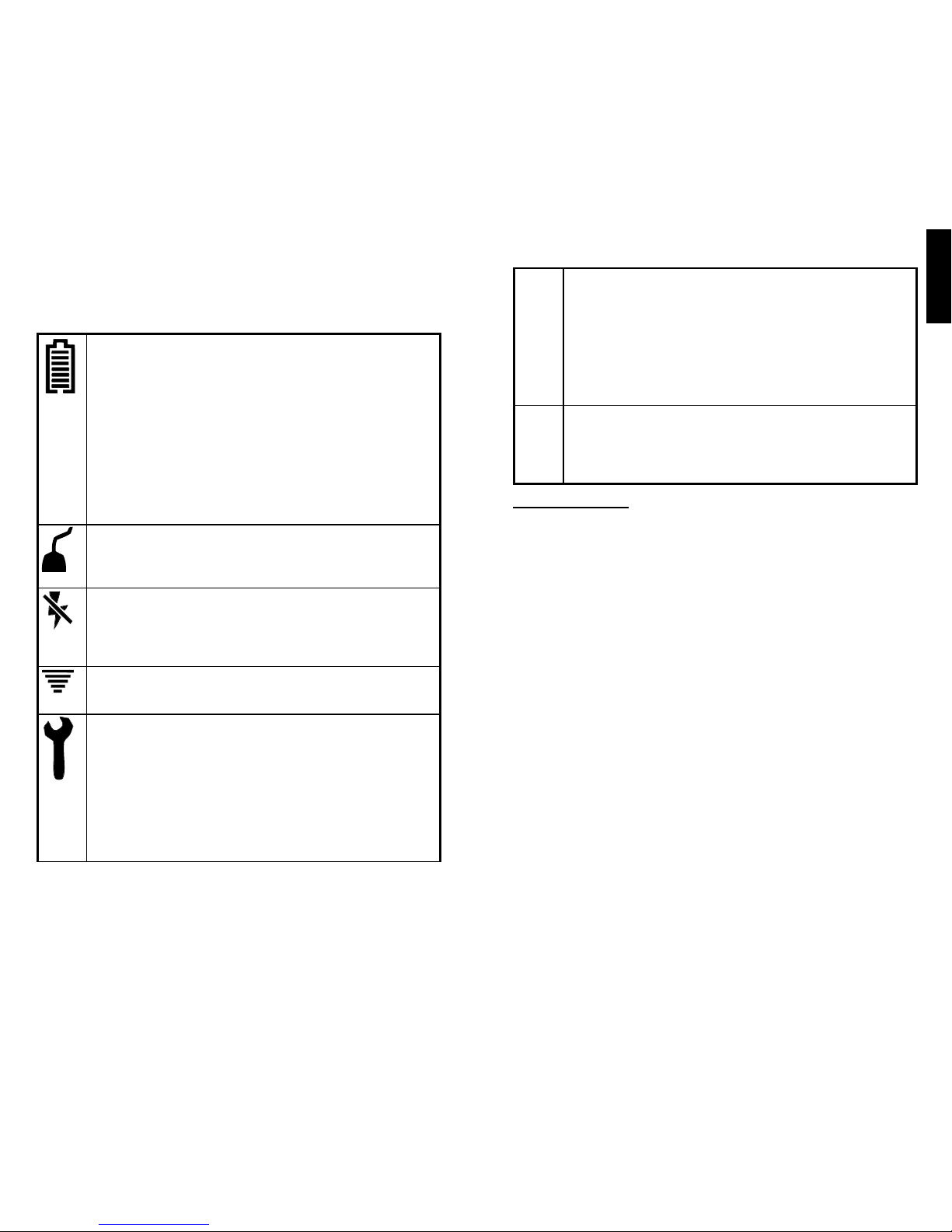
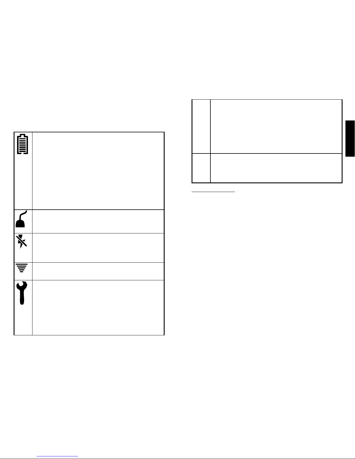
Status Screen
Icons and alpha-numeric characters on the Status Screen provide
operational feedback. These include:
Battery Level icon
The number of horizontal lines displayed in the Battery Level
icon represents the remaining battery life. Seven horizontal
lines indicate a fully charged battery whereas one horizontal line
indicates that the battery is nearly empty. A ashing Battery Level
icon signals that a replacement battery is needed. In addition, the
Stimulator will emit a beep every 15 seconds when the battery is
nearly empty (only one line displayed in the Battery Level icon).
Note: The system is designed to prohibit the start of Test mode
if there is insufcient battery life remaining to complete the
treatment.
Lead Wire Status icon
Indicates the functional status of the Lead Wire. The icon will ash
if a new Lead Wire is required.
Inactive Current icon
Indicates that current is not owing through the Lead Set. Check
the security of the Lead Connector, the adherence of the Surface
Electrode, and the placement of the Needle Electrode Clip.
Active Current icon
Indicates that current is actively owing through the Lead Set.
Service Required icon
If a fault is detected, Therapy mode will end and the Service
Required icon will appear on the screen. Contact Cogentix Medical
for further instructions.
Note: Holding down more than one button at start-up may result
in the Service Required icon appearing on the display. If this icon
appears at start-up, use the Power button to turn the device off
and on.
Treatment Status (Lower right of screen)
During Test Mode, the word “TEST” will appear on the screen.
Once Therapy mode is started, a countdown timer will appear in
the lower right of the display. This timer indicates how much time
is left in the 30 minute Therapy session.
Upon completion of Therapy, the word “END” will ash on the
screen until shutdown.
Current Setting (Center of screen)
The selected current setting is displayed at all times in the center
of the status screen. The current is adjustable in both Test and
Therapy modes.
Urgent PC Lead Set
The Lead Set transfers the electrical current from the Stimulator to the
tibial nerve and includes:
» Lead Wire: the components of the Lead Wire create the non-sterile
circuit interface between the Simulator and the patient. A one-way
t Stimulator connector is attached to the proximal end of the Lead
Wire. The distal end of the Lead Wire is split into individual wires.
One wire is attached to an adhesive-backed Surface Electrode; the
other is attached to the Needle Electrode Clip.
» Needle Electrodes: two 34 Ga. solid stainless steel Needle
Electrodes, each contained within a plastic guide tube with stop plug.
Each Needle Electrode is supplied sterile in an individual peel-open
package.
» Alcohol Pad: a prepackaged alcohol pad to clean the Needle
Electrode insertion site.
Page 7
English
12
13
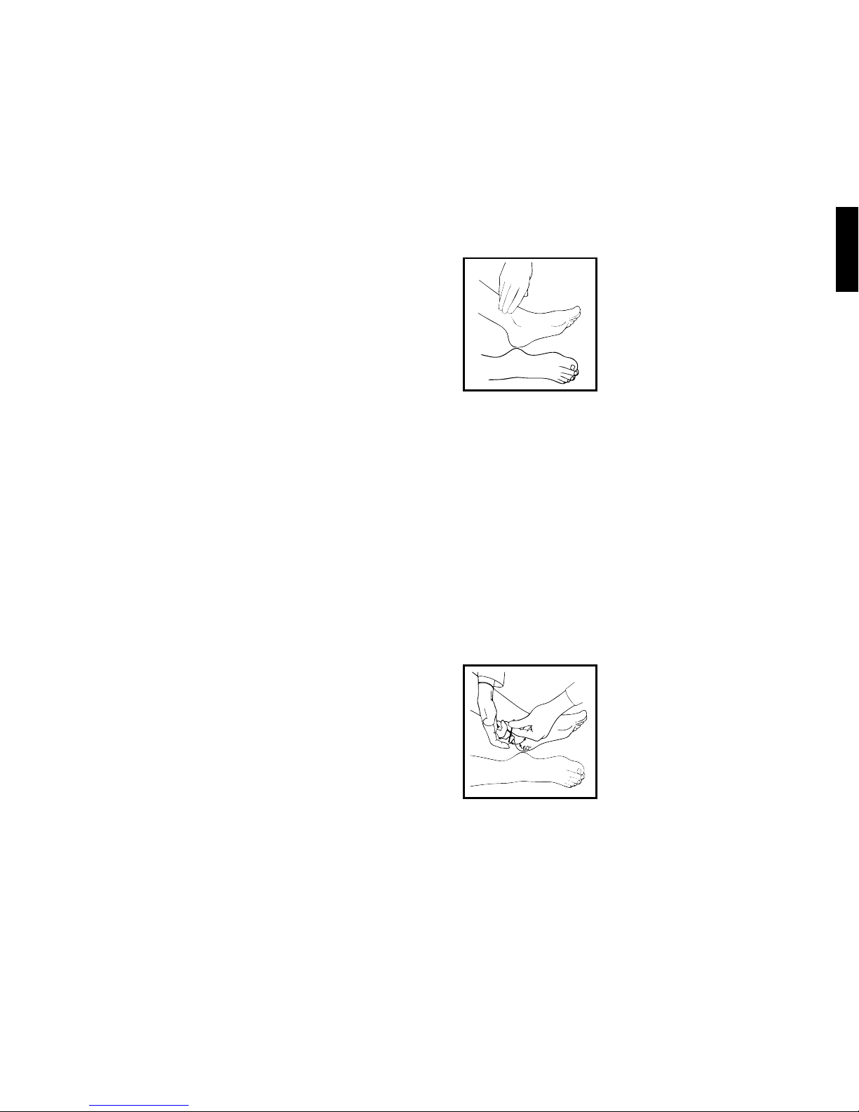
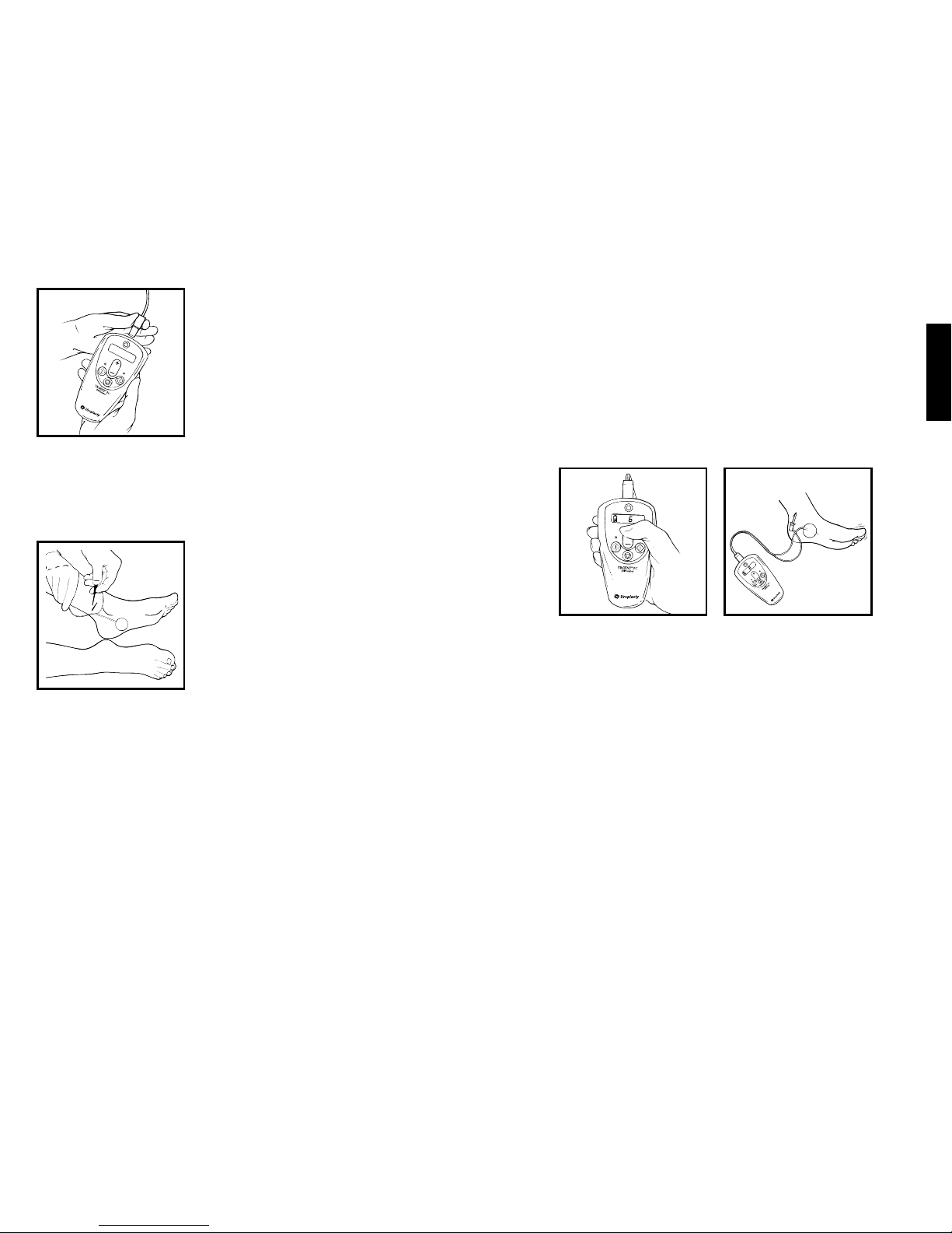
2. Insert the Needle Electrode
»
Locate the insertion site for the Needle
Electrode by identifying the location on
the lower inner aspect of either leg that
is approximately three fingerbreadths
(5 cm or 2”) cephalad to the medial
malleolus and approximately one
fingerbreadth (2 cm or ¾”) posterior to
the tibia.
» To prepare the Needle Electrode insertion site, open the Lead
Set packaging. Remove and open the Alcohol Pad. Use the
Alcohol Pad to clean the skin area surrounding the identified
insertion site.
» Place the patient in a comfortable position, supine or sitting, for
easy access to the insertion site; for example, the patient may
sit with the soles of the feet together and knees abducted and
flexed. Open the sterile Needle Electrode package and remove
the Needle Electrode/guide tube assembly.
» Place the Needle Electrode/guide tube assembly over the
identified and cleaned insertion site in a position that creates a
60-degree angle between the Needle Electrode and the ankle.
Remove the stop plug in the guide tube to release the Needle
Electrode.
» Gently tap the Needle Electrode head to pierce the skin. Once
the Needle Electrode has penetrated the skin, remove the guide
tube and advance the Needle Electrode
using a rotating motion to facilitate entry.
Note: it is important to maintain a 60-degree
angle with the Needle Electrode while
advancing it in a path that is parallel to the
tibia. When appropriately inserted,
approximately 2 cm (¾”) of the Needle
Electrode will be inserted in the leg.
INSTRUCTIONS FOR USE
This therapy, percutaneous tibial nerve stimulation (PTNS), involves
placing the Needle Electrode into the lower, inner aspect of either leg
slightly cephalad to the medial malleolus. A Surface Electrode is placed
over the medial aspect of the calcaneous on the same leg. The Lead
Wire is rst connected to the Stimulator, and then the Needle Electrode
Clip is connected to the Needle Electrode. The Stimulator produces an
adjustable electrical pulse that travels to the sacral nerve plexus via the
tibial nerve. Among other functions, the sacral nerve plexus regulates
bladder and pelvic oor function.
The patient is typically treated once per week for 30 minutes for a period
of 12 weeks. No decision to discontinue treatment should be made until
the patient completes the 12 treatments. For patients responding to
treatment, the time between treatment sessions may be slowly increased
after the initial 12 treatments, with the patient closely monitored for the
return of symptoms. If symptoms reappear or increase in severity, the
patient’s treatment schedule should revert to the last previously effective
treatment schedule.
TREATMENT PROTOCOL FOR EACH TREATMENT SESSION
1. Check Battery Level
» Before beginning any treatment session, it is advisable to
check the battery level. To check the battery level, turn on
the Stimulator by pressing and holding the Power Button for
approximately 2 seconds. An audible tone will sound and icons
will appear on the screen. Battery replacement is recommended
when there is only one line remaining in the Battery Level icon.
To conserve battery power, the Stimulator may be turned off
during patient preparation.
Note: The system is designed to prohibit the start of Test mode
if there is insufficient battery life remaining to complete the
treatment.
Page 8

English
14
15
» Using the Current Adjustment button, slowly increase the current
while monitoring the patient
for a response. Patient response
may be either motor or sensory. For some patients it is both.
Motor response is typically a toe flex or fan, or an extension of
the entire foot. Sensory response is generally described as a
tingling sensation that travels away from the insertion site,
towards the heel, arch or toes.
» Once a patient response is confirmed, reduce current setting by
one level and begin Therapy mode.
» If the incremental adjustment of amplitude fails to elicit either
a motor or a sensory response, press the Stop button and
reposition the Needle Electrode slightly. Re-enter Test mode
using the preceding instructions.
» If repositioning the Needle Electrode and repeating the current
step-up procedure fails to elicit patient response, discard the
Needle Electrode. Open the second Needle Electrode included
in the Lead Set and repeat the procedure on the other leg.
7. Conduct Therapy
» After completing Test mode, Therapy mode can be entered by
either:
1) Pressing the Stop button to end Test mode and then
pressing the Therapy button to start Therapy mode.
or 2) Pressing the Therapy button while the Test mode is still
active.
Note: Test mode is a prerequisite to Therapy mode.
» To ensure optimal treatment, the default current setting for
Therapy mode will be the final current setting in Test mode.
However, the Current Adjustment button can be used to
increase or decrease the current level at any time during
Therapy mode.
3. Connect Lead Wire to the Stimulator
» Plug the one-way fit connector of the
Lead Wire into the Stimulator’s
connection site. Verify that the one-way
fit connector is inserted correctly.
4. Attach the Surface Electrode
» Remove the adhesive backing from the Surface Electrode.
» Place the Surface Electrode near the medial aspect of the
calcaneus on the same leg as the Needle Electrode insertion.
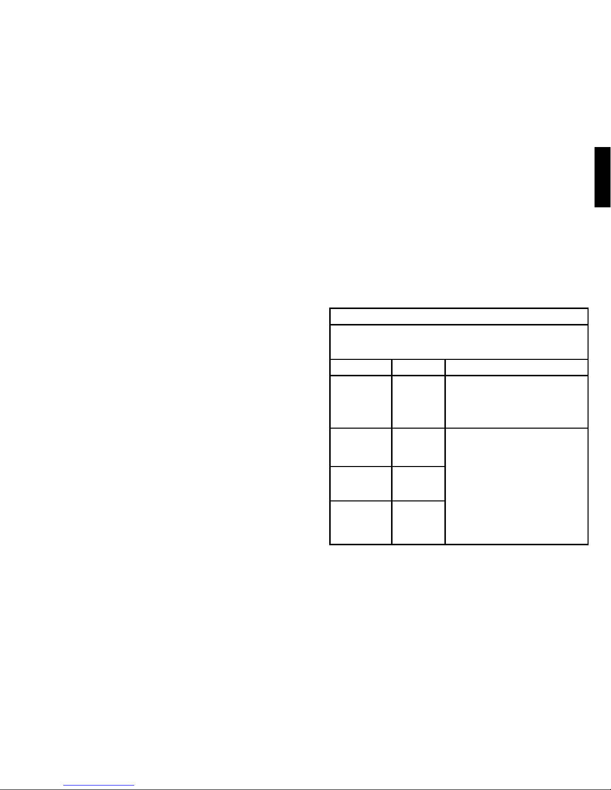
5. Attach Needle Electrode Clip
» Depress the plunger on the Needle
Electrode Clip to expose the connection
hook at the tip. Loop the connection
hook around the Needle Electrode and
release.
6. Determine Current Setting for Therapy
» Turn on the Stimulator by pressing and holding the Power button
for approximately 2 seconds. An audible tone will sound and
symbols will appear on the screen.
Note: If the Lead Wire Status icon is blinking, ensure that the
Lead Wire connector is secure in the Stimulator’s connection site.
» Enter Test mode by pressing and holding the Test button for
approximately 2 seconds. The default setting for Test mode is
level 0 (0mA current).
Note: If the Inactive Current icon appears, current is not flowing
through the Lead Set. Check the security of the Lead Wire
connector, the adherence of the Surface Electrode, and the
placement of the Needle Electrode Clip.
Page 9
English
16
17
» Therapy mode time is automatically set for 30 minutes.
» When the therapy time has elapsed, Therapy mode will
automatically end, the current will be inactive, and the Stimulator
will emit a series of three beeps.
8. Complete Treatment Session
» Turn off the Stimulator by holding down the Power button for
approximately 2 seconds.
» Remove the Needle Electrode Clip from the Needle Electrode.
» Using a smooth, fluid motion, quickly remove the Needle
Electrode from the leg. If bleeding occurs, apply slight pressure
and bandage.
» Disconnect the Lead Wire from the Stimulator and properly
dispose of Lead Set components.
» The treatment session is now complete.
TREATMENT FREQUENCY
» Conduct 12 treatments, typically once per week.
» After the initial 12 treatments, slowly increase the time between
treatments, with the patient closely monitored for the return of
symptoms.
» If symptoms reappear or increase in severity, the patient’s treatment
schedule should revert to the last previously effective treatment
schedule.
MAINTENANCE
After each treatment the surface of the Stimulator device should be
wiped down with a soft cloth. The cloth may be slightly dampened, but
not saturated, with water or with a mix of isopropyl alcohol (70%) and
water (30%).
Use only a 9V alkaline battery (e.g., Duracell) to power the Stimulator.
Never operate the Stimulator with any type of line-powered battery
eliminator or other external power source. Battery life is dependent on
the intensity of treatment; a new 9V battery will perform approximately
12 treatments at a current setting of 5mA (level 11). Recycle or
dispose of batteries in compliance with applicable local and/or national
regulations. If the Stimulator is not working properly, contact Cogentix
Medical.
PERMISSIBLE OPERATING ENVIRONMENT
» Ambient temperature 10°C to 40°C
» Relative humidity 30% to 75%
» Atmospheric pressure 700 hPa to 1060 hPa
MANUFACTURING
The Stimulator is manufactured in accordance with the safety norms set
forth by the International Electrotechnical Commission and Underwriters
Laboratory, IEC/UL 60601, including electromagnetic compatibility.
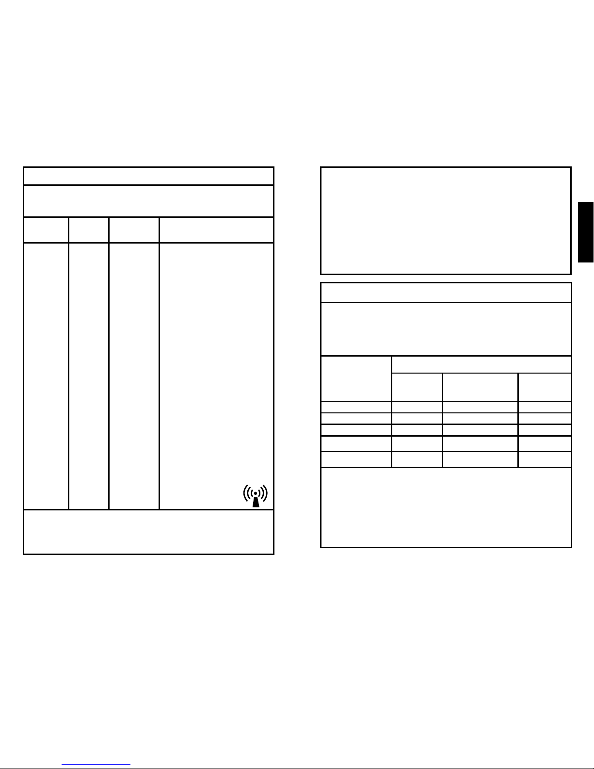
ELECTROMAGNETIC COMPATIBILITY
Guidance and Manufacturer’s Declaration – Electromagnetic Emissions
The Urgent PC Stimulator is intended for use in the electromagnetic environment
specied below. The customer or the user of the Urgent PC Stimulator should assure
that it is used in such an environment.
Emissions Test Compliance Electromagnetic Environment – Guidance
RF emissions
CISPR 11
Group 1 The Urgent PC Stimulator uses RF energy
only for its internal function. Therefore, its RF
emissions are very low and are not likely to
cause any interference in nearby electronic
equipment.
RF emissions
CISPR 11
Class B The Urgent PC Stimulator is suitable for use
in all establishments other than domestic and
those directly connected to the public lowvoltage power supply network that supplies
buildings for domestic purposes.
Harmonic
emissions
IEC 61000-3-2
Not applicable
Voltage
uctuations/
icker emissions
IEC 61000-3-3
Not applicable
Page 10
English
18
19
Guidance and Manufacturer’s Declaration – Electromagnetic Immunity
The Urgent PC Stimulator is intended for use in the electromagnetic environment
specied below. The customer or the user of the Urgent PC Stimulator should assure
that it is used in such an environment.
Immunity Test IEC 60601 Test
Level
Compliance
Level
Electromagnetic
Environment –
Guidance
Electrostatic
discharge (ESD)
IEC 61000-4-2
± 6kV contact
± 8kV air
± 6 kV
contact
± 8 kV air
Floors should be wood,
concrete or ceramic tile.
If oors are covered with
synthetic material, the
relative humidity should
be at least 30%.
Electrical fast
transient/burst
IEC 61000-4-4
± 2kV for power
supply lines
± 1kV for input/
output lines
Not
applicable
Not applicable
Surge
IEC 61000-4-5
± 1kV differential
mode
±2 kV common
mode
Not
applicable
Not applicable
Voltage
dips, short
interruptions
and voltage
variations on
power supply
input lines
IEC 61000-4-11
<5 % U
T
(>95 % dip in UT)
for 0,5 cycle
40 % U
T
(>95 % dip in UT)
for 5 cycles
70 % U
T
(>95 % dip in UT)
for 25 cycles
<5 % U
T
(>95 % dip in UT)
for 5 sec
Not
applicable
Not applicable
Power
frequency
(50/60 Hz)
magnetic eld
IEC 61000-4-8
3 A/m Not
applicable
Not applicable
Guidance and Manufacturer’s Declaration – Electromagnetic Immunity
The Urgent PC Stimulator is intended for use in the electromagnetic environment
specied below. The customer or the user of the Urgent PC Stimulator should assure
that it is used in such an environment.
Immunity
Test
IEC 60601
Test Level
Compliance
Level
Electromagnetic Environment – Guidance
Conducted
RFIEC
61000-4-6
Radiated
RFIEC
61000-4-3
3 Vrms
150 kHz to
80 MHz
3 V/m
80MHz to
2,5 GHz
3 Vrms
3 V/m
Portable and mobile RF communications
equipment should be used no closer to any part of
the Urgent PC Stimulator, including cables, than
the recommended separation distance calculated
from the equation applicable to the frequency of
the transmitter.
Recommended separation distance
d = 1,2√P
d = 1,2√P 80 MHz to 800 MHz
d = 2,3√P 800 MHz to 2,5 GHz
where P is the maximum output power rating
of the transmitter in watts (W) according to
the transmitter manufacturer and d is the
recommended separation distance in metres (m).
Field strength from xed RF transmitters, as
determined by an electromagnetic site survey,a
should be less than the compliance level in each
frequency range.
b
Interference may occur in the vicinity of equipment
marked with the following symbol:
NOTE 1 At 80 MHz and 800 MHz, the higher frequency range applies.
NOTE 2 These guidelines may not apply in all situations. Electromagnetic propagation is
affected by absorption and reection from structures, objects and people.
a
Field strengths from xed transmitters, such as base stations for radio (cellular/
cordless) telephones and land mobile radios, amateur radio, AM and FM radio broadcast
and TV broadcast cannot be predicted theoretically with accuracy. To assess the
electromagnetic environment due to xed RF transmitters, an electromagnetic site survey
should be considered. If the measured eld strength in the location in which the Urgent
PC Stimulator is used exceeds the applicable RF compliance level above, the Urgent PC
Stimulator should be observed to verify normal operation. If abnormal performance is
observed, additional measures may be necessary, such as re-orienting or relocating the
Urgent PC Stimulator
b
Over the frequency range 150 kHz to 80 MHz, eld strengths should be less than 3 V/m.
Page 11
English
20
21
Recommended Separation Distances Between Portable and Mobile RF
Communications Equipment and the Urgent PC Stimulator
The Urgent PC is intended for use in an electromagnetic environment in which radiated
RF disturbances are controlled. The customer or the user of the Urgent PC Stimulator
can help prevent electromagnetic interference by maintaining a minimum distance
between portable and mobile RF communications equipment (transmitters) and the
Urgent PC Stimulator as recommended below, according to the maximum output
power of the communications equipment.
Rated Maximum
Output Power of
Transmitter
W
Separation Distance According to Frequency of
Transmitter
m
150 kHz to 80
MHz
d = 1,2√P
80 MHz to 800 MHz
d = 1,2√P
800 MHz to 2,5
GHz
d = 2,3√P
0,01 0,12 0,12 0,23
0,1 0,38 0,38 0,73
1 1,2 1,2 2,3
10 3,8 3,8 7,3
100 12 12 23
For transmitters rated at a maximum output power not listed above, the recommended
separation distance d in metres (m) can be estimated using the equation applicable to
the frequency of the transmitter, where P is the maximum output power rating of the
transmitter in watts (W) according to the transmitter manufacturer.
NOTE 1 At 80 MHz and 800 MHz, the separation distance for the higher frequency
range applies.
NOTE 2 These guidelines may not apply in all situations. Electromagnetic propagation
is affected by absorption and reection from structure, objects and people.
WARRANTY
Cogentix Medical warrants that reasonable care has been used to
design and manufacture this product. Product will be replaced if
Cogentix Medical determines its material or workmanship is defective.
This is Cogentix Medical’s only warranty, and it excludes all other
warranties (including those implied by operation of law). Cogentix
Medical is not responsible for matters within the control of the user or
others, such as product handling and storage, patient selection and
diagnosis, and treatment procedures.
This Limited Warranty is limited to its express terms. In particular:
(1) Except as expressly provided by this Limited Warranty, COGENTIX
MEDICAL IS NOT RESPONSIBLE FOR ANY DIRECT, INCIDENTAL OR
CONSEQUENTIAL DAMAGES BASED ON ANY DEFECT, FAILURE
OR MALFUNCTION OF THE PRODUCT, WHETHER THE CLAIM IS
BASED ON WARRANTY, CONTRACT, TORT OR OTHERWISE.
(2) This Limited Warranty is made only to the purchaser of the Product.
AS TO ALL OTHERS, COGENTIX MEDICAL MAKES NO WARRANTY,
EXPRESS OR IMPLIED, INCLUDING, BUT NOT LIMITED TO, ANY
IMPLIED WARRANTY OF MERCHANTABILITY OR FITNESS FOR
A PARTICULAR PURPOSE WHETHER ARISING FROM STATUTE,
COMMON LAW, CUSTOM OR OTHERWISE. THIS LIMITED
WARRANTY SHALL BE THE EXCLUSIVE REMEDY AVAILABLE TO
ANY PERSON.
Any implied warranties of merchantability or tness are specically
excluded. Statements and descriptions in marketing literature, while
generally describing this product, do not constitute any warranties.
DISCLAIMER OF WARRANTIES
Cogentix Medical excludes all warranties and responsibilities for:
» Improper use of or tampering with the product
» Failure to follow instructions provided in this insert, and/or
» Failure to follow the Instructions for Use for Urgent PC Stimulator and
Urgent PC Lead Set.
Page 12
Deutsch
22
23
Netzschalter
Stromeinstellungstaste
Testtaste
Stopptaste
Statusanzeige
INHALT:
Beschreibung der Symbole ............................................................... 23
Indikationen ....................................................................................... 23
Produktbeschreibung ......................................................................... 24
Kontraindikationen ............................................................................. 24
Warnhinweise .................................................................................... 25
Vorsichtsmaßnahmen ........................................................................ 26
Produktspezikationen ...................................................................... 27
Gebrauchsanweisung ........................................................................ 32
Elektromagnetische Verträglichkeit ...................................................38
Gewährleistung .................................................................................. 43
Behandlungs-
taste
BESCHREIBUNG DER SYMBOLE
Verschreibungspflichtig
Artikelnummer
Seriennummer
Chargenbezeichnung
Gebrauchsanweisung beachten
Temperaturgrenzwerte: -20 °C (-4 °F) bis 60 °C (140 °F)
Relative Luftfeuchtigkeit 20 % bis 80 %, nichtkondensierend
Atmosphärischer Druck von 500 hPa bis 1060 hPa
Anwendungsteil vom Typ BF
Elektro- und Elektronik-Altgeräte (WEEE) dürfen nicht
als unsortierter städtischer Restmüll entsorgt werden.
Elektro- und Elektronik-Altgeräte müssen getrennt
gesammelt werden.
Gleichstrom
9-Volt-Alkalibatterie
Medizinprodukt geprüft durch Underwriters Laboratories
nur in Bezug auf elektrischen Schlag, Feuer und
mechanische Gefährdung. In Übereinstimmung mit
UL 60601-1, CAN/CSA C22.2 Nr. 601.1, EN 60601-1,
IEC 60601-1 und IEC 60601-2-10.
Hersteller
Bevollmächtigter in der Europäischen Union
INDIKATIONEN
Das Urgent® PC-Neuromodulationssystem ist für die Behandlung von
Patienten vorgesehen, die unter Harndrang, erhöhter Miktionsfrequenz und
SN
-20°C
60°C
20%
80%
500
hPa
1060
hPa
Page 13

Deutsch
24
25
Dranginkontinenz leiden. Das Urgent PC-System ist außerdem für die
Behandlung von Darminkontinenz indiziert.
PRODUKTBESCHREIBUNG
Das Urgent PC-Neuromodulationssystem ist ein minimalinvasives
Neuromodulationssystem, das zur Schaffung eines retrograden Zugangs
zu den Sakralnerven durch perkutane elektrische Stimulation des
Nervus tibialis vorgesehen ist. Dieses Behandlungsverfahren wird als
perkutane Stimulation des Nervus tibialis (PTNS) bezeichnet.
Das Urgent PC-Neuromodulationssystem besteht aus dem Urgent
PC-Stimulator (Stimulator) und dem Urgent PC-Draht-Set (Draht-Set).
Stimulator und Draht-Set sind separat erhältlich.
Der Stimulator ist ein batteriebetriebener, externer Impulsgenerator und
für die Mehrfachverwendung konzipiert, gebaut und hergestellt. Er ist
nur in Kombination mit dem für den einmaligen Gebrauch bestimmten
Draht-Set zu verwenden. Das Draht-Set (bestehend aus Leitungsdraht,
Nadelelektrode und Alkoholkompresse) überträgt den elektrischen Strom
über die Nadelelektrode vom Stimulator zum Nervus tibialis. Die einzigen
steril gelieferten Komponenten des Urgent PC-Neuromodulationssystems
sind die Nadelelektroden.
KONTRAINDIKATIONEN
1. Für eine effektive Behandlung und um mögliche Probleme oder
Komplikationen zu vermeiden, ist dieses Medizinprodukt für die
Anwendung bei Patienten mit der folgenden Anamnese bzw. den
folgenden Beschwerden kontraindiziert:
» Patienten mit Schrittmachern oder implantierbaren Defibrillatoren
» Patienten mit übermäßiger Blutungsneigung
» Patienten mit Nervenschädigung, die die perkutane N. tibialis-
oder Beckenbodenfunktion beeinträchtigen könnte.
2. Der Stimulator ist nicht für die intrakardiale oder transthorakale
Anwendung vorgesehen.
3. Der Stimulator darf nicht bei schwangeren Patientinnen angewendet
oder Patientinnen, die während der Anwendung dieses Produktes
eine Schwangerschaft planen.
4. Die gleichzeitige Anwendung medizinischer Überwachungsgeräte
während der Stimulation wird nicht empfohlen.
5. Dieses Medizinprodukt darf nicht in Gegenwart leicht entzündlicher
Anästhetikamischungen aus Luft, Sauerstoff oder Stickstoffoxid
verwendet werden.
WARNHINWEISE
1. Diese Gebrauchsanweisung stellt KEINE umfassende Referenz
für therapeutische Techniken zur Behandlung der für das Urgent
PC-System angegebenen Indikationen dar.
2. Der Benutzer sollte mit den entsprechenden Anwendungen und
Techniken vertraut sein, die mit dem Einsatz von Stimulator und
Draht-Set verbunden sind.
3. Den Stimulator nicht in oder in der Nähe von Wasser anwenden.
4. Stimulator und Draht-Set dürfen nicht angewendet werden, wenn
die Haut des zu behandelnden Bereichs entzündet, inziert oder auf
sonstige Weise beeinträchtigt ist. Patienten während der Anwendung
auf Schmerzen oder Hautreizungen bzw. -entzündungen beobachten.
Den Einsatz des Stimulators abbrechen, wenn der Patient über diese
Symptome oder sonstige Beschwerden klagt.
5. Batterieabdeckung nicht öffnen, wenn der Stimulator eingeschaltet
oder an den Patienten angeschlossen ist.
6. Die Anwendung des Behandlungsmodus sollte während einer
Behandlungssitzung 30 Minuten nicht überschreiten.
7. Während der Behandlung sollte der Patient bequem sitzen oder in
Rückenlage gelagert sein. Der Patient darf während der Behandlung
nicht aufstehen und umher laufen, da keine Erkenntnisse über die
Auswirkungen von Bewegung während der Behandlung vorliegen.
8. Beschädigte Komponenten des Draht-Sets (Leitungsdraht,
Nadelelektrode oder Alkoholkompresse) nicht verwenden.
9. Die Nadelelektrode bzw. die Alkoholkompresse nicht verwenden,
falls die Verpackung einer dieser Komponenten geöffnet wurde oder
beschädigt ist.
10. Die Einweg-Nadelelektroden, Oberächenelektroden und
Leitungsdrähte nicht wiederverwenden.
11. Die Komponenten des Draht-Sets in einem Abfallbehälter für
biologisch gefährliche Materialien entsorgen.
12. Die Batterie herausnehmen, wenn das Gerät voraussichtlich längere
Zeit nicht verwendet wird.
Page 14

Deutsch
26
27
13. Der gleichzeitige Anschluss von chirurgischen Hochfrequenzsystemen
am Patienten kann zu Verbrennungen an den Positionen der
Stimulatorelektroden sowie zu möglichen Beschädigungen des
Stimulators führen.
14. Der Betrieb des Gerätes in unmittelbarer Nähe (d. h. im Umkreis von
1 Meter) von Kurzwellen- oder Mikrowellen-Therapiegeräten kann
eine instabile Leistung des Stimulators zur Folge haben.
15. Die Anwendung der Elektroden in Thoraxnähe kann das Risiko von
Herzimmern erhöhen.
16. Keine Stimulation im Kopfbereich, direkt auf den Augen, im
Mundbereich, im vorderen Halsbereich (insbesondere an der
Halsschlagader), im Brustbereich, am oberen Rücken oder quer über
dem Herzbereich durchführen.
17. Der Stimulator ist mit einer Schutzvorrichtung gegen Stromschläge
ausgestattet, Schutzart „Gerät mit interner Stromversorgung“.
18. IP-Schutzgrad des Gehäuses: IPX0, kein Schutz vor eindringendem
Wasser.
19. Eine unsachgemäße Veränderung an diesem Gerät kann zu
Verletzungen des Patienten oder des Gerätebedieners führen.
VORSICHTSMASSNAHMEN
1. Vor der Anwendung des Urgent® PC-Neuromodulationssystems alle
Anweisungen in der Gebrauchsanweisung des Urgent PC-Stimulators
und in der Gebrauchsanweisung des Urgent Draht-Sets für die
PC-Stimulation sorgfältig durchlesen.
2. Vorsicht bei Patienten mit Verdacht auf oder mit bestätigten
Herzproblemen, insbesondere im Zusammenhang mit der Stimulation
oder der elektrischen Funktion des Herzens.
3. Die folgenden potentiellen Gesundheitsrisiken sind mit diesem
Gerätetyp und dieser Behandlung verbunden:
» Unwohlsein und Schmerzen (einschließlich klopfender
Schmerzen) an oder im Bereich der Stimulationsstelle
einschließlich des Unterschenkels und Fußes des Patienten
» Blutung an der Einstichstelle der Nadel
» Rötung/Entzündung an oder im Bereich der Stimulationsstelle
» Taubheitsgefühl in den Zehen
» Magenschmerzen
4. Medizinische elektrische Geräte bedürfen besonderer
Vorsichtsmaßnahmen in Bezug auf die elektromagnetische
Verträglichkeit (EMV) und müssen gemäß den EMV-Leitlinien in
dieser Gebrauchsanweisung installiert und in Betrieb genommen
werden (siehe Seite 40 für weitere Informationen).
a. Tragbare und mobile Hochfrequenz (HF)-Kommunikationsgeräte
können die Leistung dieser elektrischen medizinischen
Ausrüstung beeinträchtigen.
b. Der Endanwender dieses Produktes hat sicherzustellen, dass
es in einer geeigneten Umgebung betrieben wird.
i. Keine tragbaren und mobilen HF-Kommunikationsgeräte
(d. h. Mobiltelefone) in unmittelbarer Nähe in Betrieb
nehmen.
ii. Die Magnetfelder mit Netzfrequenzen müssen den für eine
gewerbliche oder Klinikumgebung typischen Bereichen
entsprechen.
PRODUKTSPEZIFIKATIONEN
Urgent PC-Stimulator
1. Designmerkmale:
» Leichtgewichtiges, ergonomisches, handliches Design
» Elektronische Touchpad-Bedienelemente
» Hervorstehende und geprägte Tasten für taktiles Feedback
» LCD-Anzeige zeigt Betriebsstatusan
» Einseitig gerichteter Steckverbinder für das Draht-Set
Page 15
Deutsch
28
29
2. Einstellungen der elektrischen Stromstärke:
» Impulscharakteristik:
◦ Feste Impulsfrequenz von 20 Hz
◦ Impulsdauer 200 μs
◦ Rechteckwellenform
» Widerstand 500–4,000 Ohm
Einstellungen
der elektrischen
Stromstärke
Stromstärke
(in mA)
0 0
1 0,15
2 0,5
3 1,0
4 1,5
5 2,0
6 2,5
7 3,0
8 3,5
9 4,0
Einstellungen
der elektrischen
Stromstärke
Stromstärke
(in mA)
10 4,5
11 5,0
12 5,5
13 6,0
14 6,5
15 7,0
16 7,5
17 8,0
18 8,5
19 9,0
Tastenfunktionen
Die Steuerung des Stimulators erfolgt über hervorstehende Tasten am
Gerät. Folgende Tasten stehen zur Verfügung:
Netzschalter - Ein- und Ausschalten
Hinweis: Um das Gerät ein- bzw. auszuschalten, muss der
Anwender den Netzschalter ca. 2 Sekunden gedrückt halten.
Auf diese Weise wird ein versehentlicher Statuswechsel des
Stimulators verhindert.
Testtaste (gelb) – Starten des Testmodus
Die anfängliche Standardeinstellung der Stromstärke
im Testmodus ist Stufe 0 (0 mA). Nach Beendigung des
Testmodus entspricht die letzte Einstellung der Stromstärke der
Grundeinstellung im Behandlungsmodus.
Hinweis: Der Anwender aktiviert den Testmodus, indem er ca.
2 Sekunden lang die Testtaste drückt. Auf diese Weise wird ein
versehentlicher Statuswechsel des Stimulators verhindert.
Behandlungstaste (grün) – Starten des Behandlungsmodus
Die Standardeinstellung der Stromstärke im Behandlungsmodus
entspricht der letzten Einstellung der Stromstärke im
Testmodus. Die Stromstärkenstufe kann jedoch jederzeit mit der
Stromeinstellungstaste erhöht oder verringert werden.
Hinweis: Der Anwender aktiviert den Behandlungsmodus, indem er
ca. 2 Sekunden lang die Behandlungstaste drückt. Auf diese Weise
wird ein versehentlicher Statuswechsel des Stimulators verhindert.
Stopptaste (rot) – Beendigung des Stromusses im Test- oder
Behandlungsmodus
Hinweis: Wird die Behandlung im Behandlungsmodus gestoppt
bzw. unterbrochen, wird die verbleibende Behandlungsdauer
angezeigt. Wurde die Behandlung gestoppt, muss die
Behandlungssitzung mit dem Testmodus erneut gestartet
werden. Je nach Zeitpunkt der Behandlungsunterbrechung kann
ein neues Draht-Set erforderlich sein.
Stromeinstellungstaste – Erhöhung oder Verringerung der
Stromstärke
Hinweis: Die Stromstärke kann sowohl im Test- wie auch im
Behandlungsmodus eingestellt werden.
Hinweis: Wird 15 Minuten lang keine Taste betätigt, während sich der
Stimulator weder im Test- noch im Behandlungsmodus bendet, schaltet
sich der Stimulator automatisch ab.
Page 16
Deutsch
30
31
Statusanzeige
Die Symbole und alphanumerischen Zeichen der Statusanzeige geben
den Betriebsstatus des Gerätes an. Die Bedeutung der Symbole ist wie
folgt:
Batteriesymbol
Die Anzahl der waagerechten Linien im Batteriesymbol gibt die
verbleibende Kapazität der Batterie an. Sieben waagerechte Linien
zeigen eine vollständig geladene Batterie an. Wird nur noch eine
waagerechte Linie angezeigt, ist die Batterie nahezu entladen.
Ein blinkendes Batteriesymbol zeigt an, dass eine Ersatzbatterie
erforderlich ist. Ist die Batterie nahezu entladen (nur noch eine
Linie im Batteriesymbol), ertönt zudem alle 15 Sekunden ein
akustisches Signal.
Hinweis: Falls die Batteriekapazität für eine vollständige
Behandlung nicht mehr ausreicht, verhindert das System den Start
des Testmodus.
Leitungsdraht-Symbol
Zeigt den Funktionsstatus des Leitungsdrahtes an. Das Symbol
blinkt, wenn ein neuer Leitungsdraht erforderlich ist.
Symbol „Kein Strom“
Zeigt an, dass kein Strom durch das Draht-Set ießt. Anschluss
der Drahtverbindung, Haftung der Oberächenelektrode und
Platzierung der Nadelelektrodenklemme prüfen.
Symbol „Strom aktiv“
Zeigt aktiven Stromuss durch das Draht-Set an.
Wartungssymbol
Bei Erfassung einer Störung wird der Behandlungsmodus beendet,
und in der Anzeige erscheint das Wartungssymbol. Wenden Sie
sich an Cogentix Medical, um weitere Anweisungen zu erhalten.
Hinweis: Das Drücken mehrerer Tasten beim Systemstart kann dazu
führen, dass das Wartungssymbol angezeigt wird. Erscheint dieses
Symbol beim Systemstart, das Gerät mit dem Netzschalter aus- und
wieder einschalten.
Behandlungsstatus (unten rechts in der Anzeige)
Im Testmodus wird das Wort „TEST“ eingeblendet.
Sobald der Behandlungsmodus gestartet wurde, erscheint unten
rechts eine rückwärts laufende Zeitanzeige. Diese Zeitanzeige gibt
die verbleibende Zeit der 30-minütigen Behandlung an.
Nach Abschluss der Behandlung blinkt das Wort „END“ (Ende) so
lange in der Anzeige, bis das System heruntergefahren wird.
Einstellung der Stromstärke (Mitte der Anzeige)
Die gewählte Einstellung der Stromstärke wird stets in der Mitte
der Statusanzeige eingeblendet. Die Stromstärke kann sowohl im
Test- wie auch im Behandlungsmodus eingestellt werden.
Urgent PC-Draht-Set
Das Draht-Set überträgt den elektrischen Strom vom Stimulator auf den
Nervus tibialis. Es umfasst folgende Komponenten:
» Leitungsdraht: Die Komponenten des Leitungsdrahtes bilden die
unsterile Schnittstellenschaltung zwischen Stimulator und Patient.
Am proximalen Ende des Leitungsdrahtes ist ein einseitig gerichteter
Steckverbinder für den Anschluss am Stimulator angebracht. Das distale
Ende des Leitungsdrahtes ist in Einzeldrähte unterteilt. Ein Draht ist an
einer mit selbstklebender Rückseite versehenen Oberächenelektrode
befestigt, der andere Draht ist an der Nadelelektrodenklemme befestigt.
» Nadelelektroden: Zwei 34-G-Nadelelektroden aus massivem
Edelstahl, die sich jeweils in einem Führungsrohr aus Kunststoff mit
Verschlussstopfen benden. Jede Nadelelektrode wird steril in einer
aufreißbaren Einzelverpackung geliefert.
» Alkoholkompresse: Eine abgepackte Alkoholkompresse zur Reinigung
der Einführstelle der Nadelelektrode.
Page 17

Deutsch
32
33
GEBRAUCHSANWEISUNG
Die perkutane Stimulation des Nervus tibialis (PTNS) verlangt die
Platzierung der Nadelelektrode am distalen medialen Aspekt eines
Beins leicht kranial des Malleolus medialis. Eine Oberächenelektrode
wird oberhalb des medialen Aspekts des Kalkaneus desselben Beins
platziert. Der Leitungsdraht wird zunächst mit dem Stimulator verbunden.
Anschließend wird die Nadelelektrodenklemme mit der Nadelelektrode
verbunden. Der Stimulator erzeugt einen regelbaren elektrischen Impuls,
der über den Nervus tibialis zum Sakralnervengeecht wandert. Neben
weiteren Funktionen reguliert das Sakralnervengeecht die Funktion von
Blase und Beckenboden.
Der Patient wird in der Regel über einen Zeitraum von 12 Wochen jeweils
einmal pro Woche 30 Minuten lang behandelt. Ein Abbruch der Therapie
sollte nicht vor Abschluss der 12 Behandlungssitzungen in Betracht
gezogen werden. Bei Patienten, die auf die Behandlung ansprechen,
kann nach Abschluss der ersten 12 Sitzungen die Zeit zwischen den
Behandlungen allmählich erhöht werden, wobei der Patient engmaschig
im Hinblick auf das etwaige Wiederauftreten von Symptomen beobachtet
werden muss. Falls Symptome erneut auftreten oder an Schwere
zunehmen, sollte der letzte zuvor wirksame Behandlungsplan wieder
aufgenommen werden.
BEHANDLUNGSPROTOKOLL FÜR JEDE BEHANDLUNGSSITZUNG
1. Überprüfen des Batteriestatus
» Vor Beginn jeder Behandlung sollte der Batteriestatus überprüft
werden. Dazu den Netzschalter ca. 2 Sekunden gedrückt halten,
um den Stimulator einzuschalten. Ein akustisches Sonsignal
ertönt und in der Anzeige erscheinen Symbole. Weist das
Batteriesymbol nur noch eine Linie auf wird ein Batteriewechsel
empfohlen. Um Batterieleistung zu sparen, kann der Stimulator
während der Vorbereitung des Patienten ausgeschaltet werden.
Hinweis: Reicht die Batteriekapazität für eine vollständige
Behandlung nicht mehr aus, verhindert das System den Start
des Testmodus.
2. Einführen der Nadelelektrode
»
Die Einführstelle für die Nadelelektrode
befindet sich am distalen medialen
Aspekt eines Beins ca. drei Fingerbreit
(5 cm [2”]) kranial des Malleolus medialis
und ca. einen Fingerbreit (2 cm [¾”])
posterior der Tibia.
» Zur Vorbereitung der Einführstelle für die Nadelelektrode
die Verpackung des Draht-Sets öffnen. Die abgepackte
Alkoholkompresse herausnehmen und öffnen. Mit der
Alkoholkompresse den Hautbereich um die Einführstelle reinigen.
» Den Patienten eine bequeme Position einnehmen lassen, in
Rückenlage oder sitzend, um leichten Zugang zur Einführstelle
zu haben. Der Patient kann zum Beispiel mit gegeneinander
gestellten Fußsohlen und abduzierten, gebeugten Knien
sitzen. Die Verpackung mit der sterilen Nadelelektrode öffnen
und die Nadelelektrode zusammen mit dem Führungsrohr
herausnehmen.
» Die Nadelelektrode mit Führungsrohr so über der gereinigten
Einführstelle platzieren, dass zwischen Nadelelektrode und
Knöchel ein Winkel von 60 Grad entsteht. Den Verschlussstopfen
des Führungsrohrs entfernen, um die Nadelelektrode
freizugeben.
» Vorsichtig auf das Kopfende der Nadelelektrode tippen, um
die Haut zu durchstechen. Sobald die Nadelelektrode die
Haut durchbrochen hat, das Führungsrohr entfernen und die
Nadelelektrode mit einer Drehbewegung
vorschieben, um das Einführen zu erleichtern.
Hinweis: Die Nadelelektrode muss beim
Vorschieben parallel zur Tibia einen
Winkel von 60 Grad beibehalten.Wenn die
Nadelelektrode korrekt eingeführt wurde, sitzt
die Elektrode auf einer Länge von ca. 2 cm
(¾”) im Bein.
Page 18
Deutsch
34
35
3. Leitungsdraht an Stimulator anschließen
» Den einseitig gerichteten
Steckverbinder des Leitungsdrahtes
in den Anschluss des Stimulators
stecken. Sicherstellen, dass der
einseitig gerichtete Steckverbinder
korrekt angeschlossen ist.
4. Befestigen der Oberächenelektrode
» Die Klebefolie von der Oberflächenelektrode abziehen.
» Die Oberflächenelektrode nahe dem medialen Aspekt des
Kalkaneus des Beins mit der Nagelelektrode platzieren.
5. Befestigen der Nadelelektrodenklemme
» Den Kolben der
Nadelelektrodenklemme
herunterdrücken, um den
Anschlusshaken an der Spitze
freizulegen. Den Anschlusshaken
um die Nadelelektrode legen und
freigeben.
6. Bestimmen der Stromstärkeeinstellung für die Behandlung
» Den Netzschalter etwa 2 Sekunden gedrückt halten, um den
Stimulator einzuschalten. Ein akustisches Signal ertönt, und in
der Anzeige erscheinen Symbole.
Hinweis: Wenn das Leitungsdraht-Symbol blinkt, sicherstellen,
dass der Steckverbinder des Leitungsdrahtes fest mit dem
Anschluss des Stimulators verbunden ist.
» Die Testtaste ca. 2 Sekunden gedrückt halten, um den
Testmodus zu starten. Die Standardeinstellung im Testmodus ist
Stufe 0 (Stromstärke 0 mA).
Hinweis: Wenn das Symbol „Kein Strom“ angezeigt wird, fließt
kein Strom durch das Draht-Set. Leitungsdrahtverbindung,
Haftung der Oberflächenelektrode und Platzierung der
Nadelelektrodenklemme prüfen.
» Mit der Stromeinstellungstaste langsam die Stromstärke
erhöhen und gleichzeitig die Reaktion des Patienten
überwachen. Die Reaktion des Patienten kann motorischer oder
sensorischer Art sein. Bei manchen Patienten ist die Reaktion
sowohl motorisch als sensorisch. Die motorische Reaktion
äußert sich normalerweise in einem Biegen oder Spreizen eines
Zehs oder im Strecken des ganzen Fußes. Die sensorische
Reaktion wird in der Regel als Kribbeln empfunden, das weiter
in Richtung Ferse, Fußrücken oder Zehen hinauf wandert.
» Sowie eine Patientenreaktion festzustellen ist, die Stromstärke
um eine Stufe reduzieren und mit dem Behandlungsmodus
beginnen.
» Wenn die stufenweise Einstellung der Amplitude weder eine
motorische noch eine sensorische Reaktion hervorruft, die
Stopptaste drücken und die Position der Nadelelektrode leicht
verändern. Den Testmodus, wie oben beschrieben, erneut
starten.
» Falls durch eine Umpositionierung der Nadelelektrode
und erneute stufenweise Erhöhung der Stromstärke keine
Patientenreaktion ausgelöst wird, die Nadelelektrode entsorgen.
Dem Draht-Set die zweite Nadelelektrode entnehmen und die
beschriebene Vorgehensweise am anderen Bein wiederholen.
Page 19

Deutsch
36
37
7. Durchführen der Behandlung
» Es gibt zwei Möglichkeiten, nach Abschluss des Testmodus den
Behandlungsmodus zu starten:
1) Die Stopptaste drücken, um den Testmodus zu beenden, und
anschließend die Behandlungstaste drücken, um mit dem
Behandlungsmodus zu beginnen;
oder 2) die Behandlungstaste drücken, während der Testmodus noch
aktiviert ist.
Hinweis: Die Durchführung des Testmodus ist erforderlich,
um in den Behandlungsmodus schalten zu können.
» Um eine optimale Behandlung zu gewährleisten, entspricht die
Standardeinstellung der Stromstärke im Behandlungsmodus
der letzten Einstellung der Stromstärke im Testmodus. Im
Behandlungsmodus kann die Stromstärkenstufe jedoch jederzeit
mit der Stromeinstellungstaste erhöht oder verringert werden.
» Die Dauer des Behandlungsmodus wird automatisch auf
30 Minuten eingestellt.
» Nach Ablauf der Behandlungszeit wird der Behandlungsmodus
automatisch beendet, der Stromfluss wird deaktiviert und drei
akustische Signale ertönen.
8. Abschließen der Behandlungssitzung
» Den Netzschalter etwa 2 Sekunden gedrückt halten, um den
Stimulator abzuschalten.
» Die Nadelelektrodenklemme von der Nadelelektrode abnehmen.
» Die Nadelelektrode mit einer ruhigen, flüssigen Bewegung zügig
aus dem Bein ziehen. Falls eine Blutung auftritt, leichten Druck
ausüben und einen Verband anlegen.
» Den Leitungsdraht vom Stimulator abziehen und die
Komponenten des Draht-Sets ordnungsgemäß entsorgen.
» Die Behandlungssitzung ist nun abgeschlossen.
HÄUFIGKEIT DER BEHANDLUNG
» In der Regel werden 12 Behandlungen im Abstand von einer Woche
durchgeführt.
» Nach den ersten 12 Behandlungen den Zeitabstand zwischen
den Sitzungen langsam erhöhen und genau darauf achten, ob die
Symptome des Patienten erneut auftreten.
» Falls Symptome erneut auftreten oder an Schwere zunehmen, sollte
der letzte zuvor wirksame Behandlungsplan wieder aufgenommen
werden.
WARTUNG
Die Oberächen des Stimulators nach jeder Behandlung mit einem
weichen Tuch abwischen. Das Tuch mit etwas Wasser oder einer
Mischung aus Isopropylalkohol (70 %) und Wasser (30 %) anfeuchte,
jedoch nicht durchtränken.
Für die Stromversorgung des Stimulators ausschließlich eine
9-Volt-Alkalibatterie (Duracell) verwenden. Den Stimulator in keinem
Fall an einen Anodennetzanschluss jeglicher Art oder eine sonstige
externe Stromquelle anschließen. Die Lebensdauer der Batterie hängt
von der Intensität der Behandlungen ab. Eine neue 9-Volt-Batterie
reicht bei einer Stromstärkeeinstellung von 5 mA (Stufe 11) für etwa
12 Behandlungen aus. Die Batterien in Übereinstimmung mit den
geltenden lokalen und/oder nationalen gesetzlichen Vorschriften
recyceln oder entsorgen. Bei Funktionsstörungen des Stimulators,
wenden Sie sich an Cogentix Medical.
ZULÄSSIGE BETRIEBSUMGEBUNG
» Umgebungstemperatur 10 °C bis 40 °C
» Relative Luftfeuchtigkeit 30 % bis 75 %
» Atmosphärischer Druck 700 hPa bis 1060 hPa
NORMEN
Die Herstellung des Stimulators erfolgt in Übereinstimmung mit den
von der International Electrotechnical Commission (IEC) und dem
Underwriters Laboratories (UL) gemäß IEC/UL 60601 festgelegten
Sicherheitsnormen, einschließlich elektromagnetische Verträglichkeit.
Page 20
Deutsch
38
39
ELEKTROMAGNETISCHE VERTRÄGLICHKEIT
Leitlinien und Herstellererklärung – elektromagnetische Strahlung
Der Urgent PC-Stimulator ist für den Gebrauch im nachfolgend festgelegten
elektromagnetischen Umfeld vorgesehen. Der Kunde oder der Anwender des Urgent PCStimulators hat sicherzustellen, dass das Gerät in einem solchen Umfeld verwendet wird.
Emissionsprüfung Konformität Elektromagnetisches Umfeld – Leitlinien
HF-Emissionen
CISPR 11
Gruppe 1 Der Urgent PC-Stimulator verwendet HF-
Energie ausschließlich für seine internen
Funktionen. Die HF-Emissionen sind daher
sehr niedrig. Die Wahrscheinlichkeit, dass sie
Störungen in elektronischen Geräten in der
Nähe verursachen, ist sehr gering.
HF-Emissionen
CISPR 11
Klasse B Der Urgent PC-Stimulator eignet sich für den
Gebrauch in allen Einrichtungen, mit Ausnahme
von Privatwohnungen und Einrichtungen
mit direktem Anschluss an das öffentliche
Niederspannungsstromnetz zur Versorgung
von Wohngebäuden.
Harmonische
Emissionen
IEC 61000-3-2
Nicht
zutreffend
Spannungsschwankungen/
Flickeremissionen
IEC 61000-3-3
Nicht
zutreffend
Leitlinien und Herstellererklärung – elektromagnetische Störfestigkeit
Der Urgent PC-Stimulator ist für den Gebrauch im nachfolgend festgelegten
elektromagnetischen Umfeld vorgesehen. Der Kunde oder der Anwender des Urgent PCStimulators hat sicherzustellen, dass das Gerät in einem solchen Umfeld verwendet wird.
Prüfung der
Störfestigkeit
IEC 60601 Prüfschärfe Konformitäts-
stufe
Elektromagnetisches
Umfeld – Leitlinien
Elektrostatische
Entladung (ESD)
IEC 61000-4-2
± 6 kV Kontakt
± 8 kV Luft
± 6 kV Kontakt
± 8 kV Luft
Der Fußboden sollte
aus Holz, Beton
oder Keramikiesen
bestehen. Falls der
Fußbodenbelag aus
synthetischem Material
besteht, sollte die
relative Luftfeuchtigkeit
mindestens 30 %
betragen.
Schnelle transiente
Störgrößen/Burst
IEC 61000-4-4
± 2 kV für Stromversorgungsleitungen
± 1 kV für Ein-/ Ausgangsleitungen
Nicht
zutreffend
Nicht zutreffend
Stoßspannung
IEC 61000-4-5
± 1 kV
Differentialtaktspannung
± 2 kV Gleichtaktspannung
Nicht
zutreffend
Nicht zutreffend
Spannungseinbrüche,
Kurzzeitunterbrechungen und
Spannungsschwankungen in
StromversorgungsEingangsleitungen
IEC 61000-4-11
< 5 % U
T
(> 95 % Spannungsabfall
in UT) für 0,5 Zyklen
40 % U
T
(> 95 % Spannungsabfall in
UT) für 5 Zyklen
70 % U
T
(> 95 % Spannungsabfall
in UT) für 25 Zyklen
< 5 % U
T
(> 95 % Spannungsabfall
in UT) für 5 s
Nicht
zutreffend
Nicht zutreffend
Netzfrequenz
(50/60 Hz) Magnetfeld
IEC 61000-4-8
3 A/m Nicht
zutreffend
Nicht zutreffend
Page 21
Deutsch
40
41
a
Die Feldstärke von stationären Sendern wie Basisstationen für Funktelefone (Mobil-/
schnurlose Telefone) sowie Landmobilfunk, Amateurfunk, AM- und FM-Radiosender
und Fernsehsender kann nicht präzise theoretisch berechnet werden. Zur Beurteilung
der elektromagnetischen Umgebung stationärer HF-Sender sollte unter Umständen ein
elektromagnetisches Standortgutachten durchgeführt werden. Überschreitet die gemessene
Feldstärke am Standort des Urgent PC-Stimulators das relevante HF-Compliance-Niveau
(siehe oben), muss der Urgent PC-Stimulator auf ordnungsgemäße Betriebstätigkeit
hin kontrolliert werden. Zeigt das Gerät anomale Leistungen, sind eventuell zusätzliche
Maßnahmen wie eine Neuausrichtung bzw. Umstellung des Urgent PC-Stimulators
notwendig.
b
Im Frequenzbereich zwischen 150 kHz und 80 MHz dürfen die Feldstärken 3 V/m nicht
überschreiten.
Empfohlener Schutzabstand zwischen tragbaren und mobilen
HF-Kommunikationsgeräten und dem Urgent PC-Stimulator
Der Urgent PC ist für die Verwendung in einem elektromagnetischen Umfeld vorgesehen,
in der HF-Störstrahlungen kontrolliert werden. Der Kunde bzw. der Anwender des Urgent
PC-Stimulators kann zur Verhinderung von elektromagnetischen Störungen beitragen,
indem er gemäß der Empfehlung unten, die sich nach der maximalen Ausgangsleistung der
Kommunikationsausrüstung richtet, einen Mindestabstand zwischen der tragbaren und mobilen
HF-Ausrüstung (Sender) und Urgent PC-Stimulator einhält.
Maximale Nenn-
ausgangsleistung des
Senders
W
Schutzabstand entsprechend der Senderfrequenz m
150 kHz bis
80 MHz
d = 1,2√P
80 MHz bis 800 MHz
d = 1,2√P
800 MHz bis
2,5 GHz
d = 2,3√P
0,01 0,12 0,12 0,23
0,1 0,38 0,38 0,73
1 1,2 1,2 2,3
10 3,8 3,8 7,3
100 12 12 23
Für Sender mit einer anderen maximalen Ausgangsnennleistung als oben aufgeführt, kann
der empfohlene Abstand d in Metern (m) anhand der entsprechenden Gleichung für die
Senderfrequenz bestimmt werden, wobei P die maximale Ausgangsnennleistung des Senders in
Watt (W) gemäß Herstellerangaben des Senders darstellt.
HINWEIS 1 Bei 80 MHz und 800 MHz gilt der Schutzabstand für den höheren Frequenzbereich.
HINWEIS 2 Diese Richtlinien treffen eventuell nicht in allen Situationen zu. Die Ausbreitung
elektromagnetischer Wellen hängt von der Absorption und Reexion derselben von Strukturen,
Gegenständen und Personen ab.
Leitlinien und Herstellererklärung – elektromagnetische Störfestigkeit
Der Urgent PC-Stimulator ist für den Gebrauch im nachfolgend festgelegten elektromagnetischen
Umfeld vorgesehen. Der Kunde oder der Anwender des Urgent PC-Stimulators hat sicherzustellen,
dass das Gerät in einem solchen Umfeld verwendet wird.
Prüfung der
Störfestigkeit
IEC 60601
Prüfschärfe
Konformitätsstufe Elektromagnetisches Umfeld – Leitlinie
Abgeleitete
HF
IEC
61000-4-6
Abgestrahlte
HF
IEC
61000-4-3
3 Vrms
150 kHz bis
80 MHz
3 V/m
80 MHz bis
2,5 GHz
3 Vrms
3 V/m
Bei der Verwendung tragbarer und mobiler
HF-Kommunikationsausrüstungen sollte
der empfohlene Abstand zum Urgent
PC-Stimulator einschließlich Kabel
eingehalten werden, der sich aus der für
die Frequenz des Senders geltenden
Gleichung ergibt.
Empfohlener Schutzabstand
d = 1,2√P
d = 1,2√P 80 MHz bis 800 MHz
d = 2,3√P 800 MHz bis 2,5 GHz
Wobei P die maximale Ausgangsleistung
des Senders in Watt (W) und d der
empfohlene Abstand in Metern (m)
gemäß Angaben des Senderherstellers
ist.
b
Die Feldstärke der stationären
HF-Sender, ermittelt durch
elektromagnetische Prüfung
a
, muss
in jedem Frequenzbereich unter dem
Compliance-Niveau liegen.
b
In der Umgebung von Geräten, die
mit diesem Symbol gekennzeichnet sind,
können Interferenzen auftreten:
HINWEIS 1 Bei 80 MHz und 800 MHz gilt der höhere Frequenzbereich.
HINWEIS 2 Diese Richtlinien treffen eventuell nicht in allen Situationen zu. Die Ausbreitung
elektromagnetischer Wellen hängt von der Absorption und Reexion derselben von Strukturen,
Gegenständen und Personen ab.
Page 22

Deutsch
42
43
EINGESCHRÄNKTE GEWÄHRLEISTUNG
Cogentix Medical gewährleistet, dass bei der Entwicklung und
Herstellung dieses Produkts die erforderliche Sorgfalt aufgewendet
wurde. Das Produkt wird ersetzt, wenn Cogentix Medical Materialoder Ausführungsmängel feststellt. Alle sonstigen Gewährleistungen
von Cogentix Medical, und sämtliche anderen Gewährleistungen
(einschließlich der per Gesetz implizierten) sind ausgeschlossen.
Cogentix Medical übernimmt keine Verantwortung für Angelegenheiten,
die unter der Kontrolle des Anwenders oder sonstiger Personen liegen,
wie etwa Handhabung und Lagerung des Produkts, Auswahl der
Patienten, Diagnosestellung und Behandlungsverfahren.
Diese beschränkte Gewährleistung ist auf ihre ausdrücklich vereinbarten
Bedingungen beschränkt. Insbesondere:
(1) Sofern nicht ausdrücklich in dieser beschränkten Gewährleistung
vorgesehen, ÜBERNIMMT COGENTIX MEDICAL KEINE
VERANTWORTUNG FÜR JEGLICHE DIREKTEN ODER
INDIREKTEN SCHÄDEN BZW. FOLGESCHÄDEN AUFGRUND
EINES DEFEKTS, VERSAGENS ODER EINER FEHLFUNKTION DES
PRODUKTS, UNABHÄNGIG DAVON OB SICH DIE FORDERUNG
AUF GEWÄHRLEISTUNG, VERTRAG, SCHADENERSATZ ODER
SONSTIGES BEGRÜNDET.
(2) Diese beschränkte Gewährleistung gilt nur für den Käufer des
Produkts. DRITTEN GEWÄHRT COGENTIX MEDICAL WEDER
IMPLIZITE NOCH EXPLIZITE GARANTIEN, EINSCHLIESSLICH
JEGLICHE IMPLIZITE GARANTIEN, DASS DIE PRODUKTE
VON MARKTGÄNGIGER QUALITÄT UND/ODER FÜR DEN
NORMALEN GEBRAUCH ODER FÜR EINEN BESTIMMTEN ZWECK
GEEIGNET SIND, UNABHÄNGIG DAVON, OB DIESE SICH AUS
GESETZESRECHT, GEMEINEM RECHT, GEWOHNHEIT ODER AUS
SONSTIGEN REGELUNGEN HERLEITEN. DIESE BESCHRÄNKTE
GEWÄHRLEISTUNG IST DER AUSSCHIESSLICH GELTENDE
RECHTSBEHELF.
Stillschweigende Gewährleistungen dass die Produkte von
marktgängiger Qualität und/oder für den normalen Gebrauch oder
für einen bestimmten Zweck geeignet sind, sind ausdrücklich
ausgeschlossen. Darstellungen und Beschreibungen in der
Marketingliteratur sind allgemeine Produktbeschreibungen, die keinerlei
Garantieansprüche begründen.
Stillschweigende Gewährleistungen der Marktgängigkeit oder Eignung
werden spezisch ausgeschlossen. Darstellungen und Beschreibungen
in Marketing-Literatur, die dieses Produkt allgemein beschreiben,
begründen keinerlei Gewährleistungen.
AUSSCHLUSS VON GEWÄHRLEISTUNGEN
Cogentix Medical lehnt jegliche Haftung oder Verantwortung ab bei:
» Unsachgemäßer Anwendung oder Manipulation des Produktes
» Nichtbefolgung der in dieser Packungsbeilage aufgeführten
Anweisungen und/oder
» Nichtbefolgung der Gebrauchsanweisung für den Urgent
PC-Stimulator und das Urgent PC-Draht-Set
Page 23
Español
44
45
Alimentación
Botón de
ajuste de la
corriente
Botón de
prueba
Botón de
parada
Botón de
terapia
Pantalla de
estado
CONTENIDO:
Descripción de los símbolos .............................................................. 45
Indicaciones de uso ........................................................................... 46
Descripción del producto ................................................................... 46
Contraindicaciones de uso ................................................................ 46
Advertencias ...................................................................................... 47
Precauciones ..................................................................................... 48
Especicaciones del producto ........................................................... 49
Instrucciones de uso .......................................................................... 53
Compatibilidad electromagnética ...................................................... 59
Garantía ............................................................................................. 62
DESCRIPCIÓN DE LOS SÍMBOLOS
Uso sólo por prescripción facultativa
Número de referencia del producto
Número de serie
Número de lote
Consulte las instrucciones de uso
Límite de temperatura de -20 °C (-4 °F) a 60 °C (140 °F)
Humedad relativa del 20 % al 80 %, sin condensación
Presión atmosférica de 500 hPa a 1060 hPa
Parte aplicada tipo BF
Los equipos eléctricos y electrónicos desechables
(RAEE) no deben desecharse como basura municipal
no clasificada; dichos productos deben desecharse de
forma separada.
Corriente continua
Pila alcalina de 9 V
Clasificado por Underwriters Laboratories como
equipamiento médico solamente con respecto a los
riesgos de descarga eléctrica, incendio y riesgos
mecánicos. Según la normativa UL 60601-1,
CAN/CSA C22.2 n.º 601.1, EN 60601-1, IEC 60601-1
e IEC 60601-2-10.
Fabricante
Representante autorizado en la Comunidad Europea
SN
-20°C
60°C
20%
80%
500
hPa
1060
hPa
Page 24

Español
46
47
INDICACIONES DE USO
El sistema de neuromodulación Urgent® PC está indicado para el
tratamiento de pacientes que sufren de urgencia urinaria, frecuencia
urinaria e incontinencia urinaria. El Urgent PC también está indicado para
el tratamiento de la incontinencia fecal.
DESCRIPCIÓN DEL PRODUCTO
El sistema de neuromodulación Urgent PC es mínimamente invasivo y
está diseñado para brindar acceso retrógrado al nervio sacro mediante
la estimulación eléctrica percutánea del nervio tibial. El método de
tratamiento es conocido como estimulación percutánea del nervio tibial
(EPNT).
El sistema de neuromodulación Urgent PC se compone del estimulador
Urgent PC (estimulador) y el juego de cables Urgent PC (juego de cables).
El estimulador y el juego de cables se comercializan por separado.
El estimulador es un generador externo de pulsos accionado a pilas, y
está diseñado, construido y fabricado para múltiples usos. El estimulador
debe ser usado sólo con el juego de cables de un solo uso. El juego
de cables (de cables conductores, electrodos de aguja y toallitas de
alcohol) transere la corriente eléctrica del estimulador al nervio tibial
a través del electrodo de aguja. Los únicos componentes del sistema
de neuromodulación Urgent PC que se suministran estériles son los
electrodos de aguja.
CONTRAINDICACIONES DE USO
1. Para que el tratamiento sea efectivo y evitar posibles problemas
o complicaciones, el uso del dispositivo está contraindicado en
aquellos pacientes que presenten los siguientes antecedentes o
estados:
» Pacientes con marcapasos o desfibriladores implantables.
» Pacientes propensos a excesiva hemorragia.
» Pacientes con daño neurológico que podría repercutir en el nervio
tibial percutáneo o en la función del suelo de la pelvis.
2. El estimulador no está indicado para uso intracardíaco ni
transtorácico.
3. No usar el estimulador en pacientes embarazadas o que planean
quedarse embarazadas mientras usan este producto.
4. No se recomienda el uso simultáneo de equipos de monitorización
médica durante la estimulación.
5. Este dispositivo no es apto para uso en presencia de una mezcla
anestésica inamable con aire, o con oxígeno u óxido nitroso.
ADVERTENCIAS
1. Estas instrucciones de uso NO constituyen una referencia exhaustiva
a las técnicas terapéuticas para las indicaciones de tratamiento
señaladas para el dispositivo Urgent PC.
2. Los usuarios deben familiarizarse con la aplicación y las técnicas
correctas implicadas en el uso del estimulador y el juego de cables.
3. No utilizar el estimulador dentro del agua o cerca de la misma.
4. No utilizar el estimulador ni el juego de cables si la piel en la zona de
aplicación estuviera inamada, infectada o de algún modo dañada.
Monitorizar a los pacientes durante el tratamiento por si apareciera
dolor o irritación/inamación cutánea. Suspender el uso del
estimulador si el paciente presenta estos síntomas o cualquier otra
incomodidad.
5. No abra la cubierta de las pilas con el estimulador encendido o
conectado al paciente.
6. Los pacientes no deben pasar más de 30 minutos en el modo de
terapia durante una única sesión de tratamiento.
7. El paciente debe estar cómodamente sentado, o en posición supina,
mientras dure el tratamiento. El paciente no debe levantarse ni
caminar hasta que el tratamiento haya terminado, ya que la movilidad
durante el tratamiento no ha sido evaluada.
8. No utilizar ningún componente del juego de cables (cable de
derivación, electrodo de aguja o toallita de alcohol) si presenta
cualquier tipo de daño.
9. No utilizar el electrodo de aguja o la toallita de alcohol si el envoltorio
de cualquiera de estos componentes ha sido abierto o presenta
daños.
10. No reutilizar el electrodo de aguja, el electrodo de supercie o el cable
de derivación que son de un sólo uso.
11. Desechar los componentes usados del juego de cables en un
contenedor de desecho para materiales de riesgo biológico.
12. Retirar la pila si el equipo no se va a emplear durante cierto tiempo.
Page 25
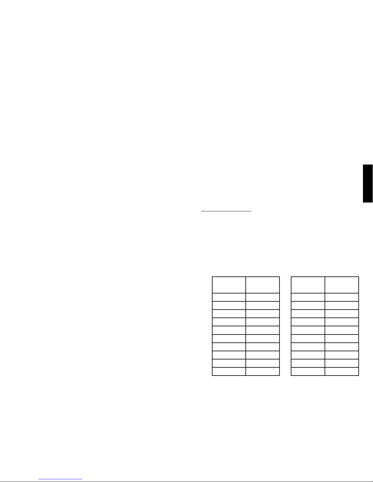
Español
48
49
13. La conexión simultánea de un paciente a un equipo quirúrgico de
alta frecuencia puede ocasionar quemaduras en el lugar de los
electrodos del estimulador y posibles daños al mismo.
14. El funcionamiento del dispositivo a muy escasa distancia (por
ejemplo, 1 metro) de equipos para terapia de onda corta o
microondas puede generar inestabilidad en la salida del estimulador.
15. La aplicación de los electrodos cerca del tórax puede aumentar el
riesgo de brilación cardíaca.
16. No aplique la estimulación en la cabeza o a través de esta,
directamente sobre los ojos, cubriendo la boca, en la parte frontal del
cuello (especialmente en el seno carótido), el pecho, la parte superior
de la espalda o sobre el corazón.
17. El estimulador presenta protección contra descargas de corriente, del
tipo de los “Equipos con alimentación eléctrica interna”.
18. La carcasa del estimulador es de tipo IPX0 y no presenta protección
alguna frente a la entrada de agua.
19. Si se modica el equipo sin la debida autorización, el paciente o el
operador del dispositivo podrían sufrir lesiones.
PRECAUCIONES
1. Antes de usar el sistema de neuromodulación Urgent® PC, lea
y comprenda todas las instrucciones de los manuales de uso
del estimulador Urgent
®
PC y del juego de cables Urgent® PC.
2. Deberá tenerse precaución en los pacientes con problemas cardíacos
sospechados o diagnosticados, especialmente los relacionados con la
estimulación o el funcionamiento eléctrico del corazón.
3. Los siguientes son riesgos potenciales para la salud asociados a
este tipo de dispositivos y de terapia:
» Incomodidad y dolor (incluyendo dolor punzante) en el sitio de
estimulación o cerca de él, incluyendo la parte inferior de la
pierna y el pie del paciente.
» Hemorragia en el lugar de punción de la aguja.
» Enrojecimiento/inflamación en el lugar de estimulación o cerca
de él.
» Entumecimiento de los dedos de los pies.
» Dolor de estómago.
4. Los equipos médicos eléctricos requieren precauciones especiales
respecto de la compatibilidad electromagnética (CEM) y deben
instalarse y ponerse en funcionamiento según las directrices de
CEM que se ofrecen (véase más información en la página 59).
a. Los equipos de comunicación por radiofrecuencia (RF) portátiles
y móviles pueden afectar a los equipos médicos eléctricos.
b. El usuario nal de este producto debe asegurarse de que se
utiliza en un entorno adecuado.
i. No deben usarse cerca de este producto equipos
portátiles y móviles de comunicación por RF (p. ej.,
teléfonos móviles).
ii. Los campos magnéticos por frecuencia de la red deben
encontrarse a los niveles característicos de un entorno
comercial, hospitalario o clínico normal.
ESPECIFICACIONES DEL PRODUCTO
Estimulador Urgent PC
1. Características de diseño:
» Diseño ligero, ergonómico y manual.
» Controles electrónicos mediante pantalla táctil.
» Botones elevados y en relieve para ofrecer percepción táctil.
» Pantalla de estado LCD para ofrecer el estado operativo.
» Lugar de conexión del juego de cables con encaje en sentido
único.
2. Valores eléctricos:
Valor de la
corriente
Corriente
(en mA)
0 0
1 0,15
2 0,5
3 1,0
4 1,5
5 2,0
6 2,5
7 3,0
8 3,5
9 4,0
Valor de la
corriente
Corriente
(en mA)
10 4,5
11 5,0
12 5,5
13 6,0
14 6,5
15 7,0
16 7,5
17 8,0
18 8,5
19 9,0
Page 26
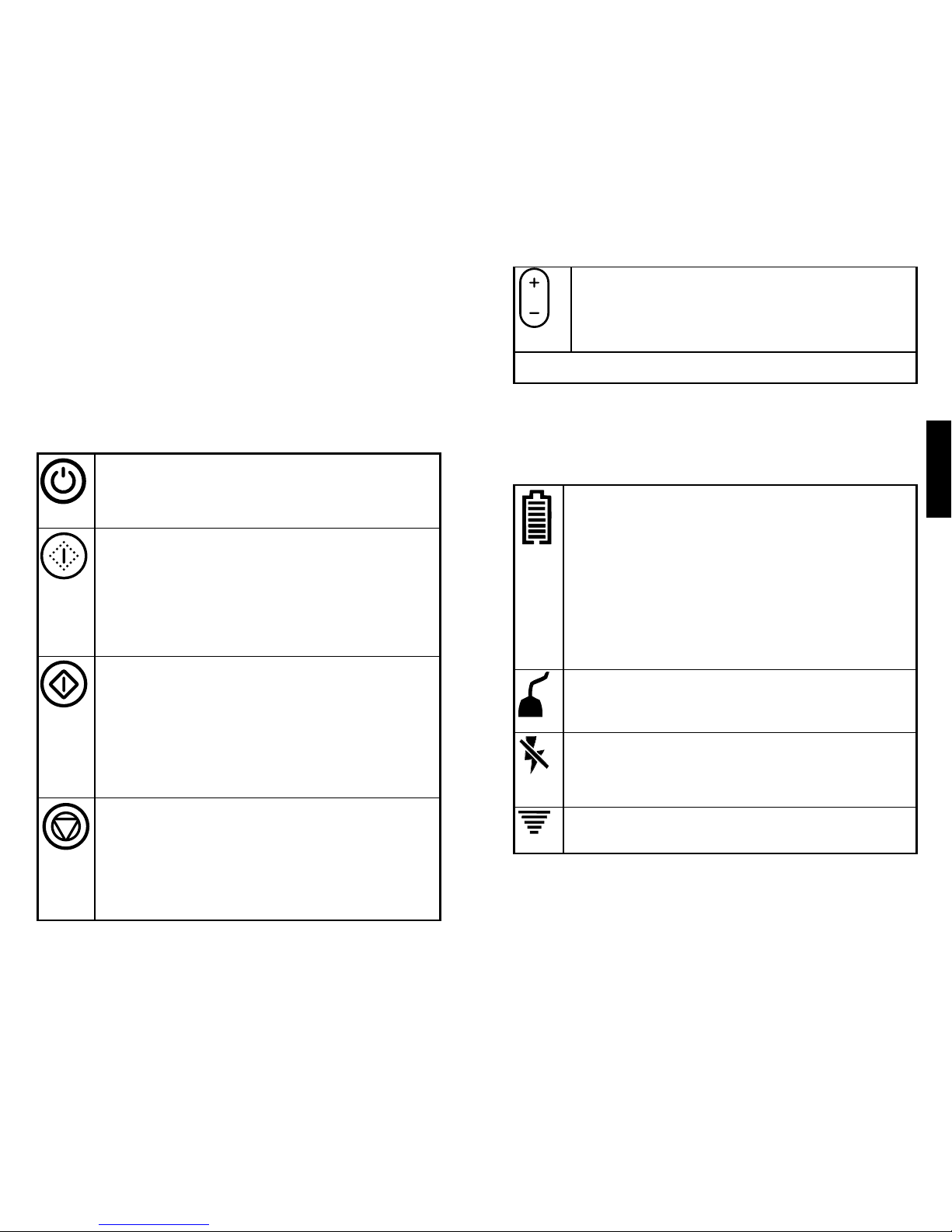
Español
50
51
» Características del pulso:
◦ Frecuencia fija del pulso de 20 Hz.
◦ Anchura del pulso de 200 µsegundos.
◦ Forma de onda cuadrada.
» Resistencia de 500 a 4000 ohmios.
Botones de control
El estimulador está controlado por botones elevados en el dispositivo.
Éstos botones son:
Botón de encendido: enciende y apaga el dispositivo
Nota: para encender o apagar el dispositivo, el usuario tiene que presionar
el botón de encendido durante unos 2 segundos. Esto está diseñado para
proteger al estimulador de cambios de estado involuntarios.
Botón de prueba (amarillo): inicia el modo de prueba
Al entrar en el modo de prueba, el valor de la corriente por defecto
será de 0 (0 mA). Al nal del modo de prueba, el valor nal de la
corriente será el valor basal en el modo de terapia.
Nota: para activar el modo de prueba, el usuario tiene que presionar el
botón del modo de prueba durante unos 2 segundos. Esto está diseñado
para proteger al estimulador de cambios de estado involuntarios.
Botón de terapia (verde): inicia el modo de terapia
El valor de la corriente por defecto para el modo de terapia será el
valor nal de la corriente en el modo de prueba. No obstante, se
puede utilizar el botón de ajuste de la corriente para aumentar o
reducir el nivel de la corriente en cualquier momento.
Nota: para activar el modo de terapia, el usuario tiene que presionar el
botón del modo de terapia durante unos 2 segundos. Esto está diseñado
para proteger al estimulador de cambios de estado involuntarios.
Botón de parada (rojo): interrumpe el ujo de corriente en los modos
de prueba o de terapia
Nota: si se detiene o interrumpe el tratamiento durante el modo de
terapia, aparece el tiempo restante del modo de terapia. Una vez
detenido, habrá que reiniciar la sesión de tratamiento empezando por
el modo de prueba. En función de cuándo fue interrumpida la sesión,
puede ser necesario un nuevo juego de cables.
Botón de ajuste de la corriente: aumenta o reduce la corriente
Nota: la corriente se puede ajustar tanto en el modo de prueba como
en el de terapia.
Nota: si el estimulador no está en el modo de prueba ni en el de terapia y no se
pulsa ningún botón durante 15 minutos, el estimulador se apagará.
Pantalla de estado
Los iconos y caracteres alfanuméricos de la pantalla de estado ofrecen
información operativa. Entre ellos se encuentran:
Icono de nivel de la pila
El número de líneas horizontales presentadas en el icono de nivel de
la pila representa el tiempo de duración restante de la pila. Siete líneas
horizontales indican una pila completamente cargada mientras que una
línea horizontal indica que la pila está casi agotada. Si el icono de nivel
de la pila parpadea, indica que hay que cambiar la pila. Además, el
estimulador emitirá un tono cada 15 segundos cuando la pila esté casi
agotada (sólo aparece una línea en el icono de nivel de la pila).
Nota: el sistema está diseñado para impedir el inicio del modo de
prueba si no queda suciente energía en la pila para completar el
tratamiento.
Icono de estado del cable de derivación
Indica el estado funcional del cable de derivación. El icono parpadea si
hiciera falta un nuevo cable de derivación.
Icono de corriente inactiva
Indica que la corriente no está uyendo por el juego de cables.
Compruebe la seguridad del conector del cable, la adherencia del
electrodo de supercie y la colocación de la pinza del electrodo de aguja.
Icono de corriente activa
Indica que la corriente está uyendo activamente por el juego de cables.
Page 27

Español
52
53
Icono de servicio necesario
Si se detecta una avería, el modo de terapia terminará y aparecerá en
la pantalla el icono de servicio necesario. Póngase en contacto con
Cogentix Medical para recibir más instrucciones.
Nota: si se presiona más de un botón en el encendido, puede
aparecer el icono de servicio necesario en la pantalla. Si aparece
este icono en el encendido, utilice el botón de apagado para
encender y apagar el dispositivo.
Estado del tratamiento (parte inferior derecha de la pantalla)
Durante el modo de prueba, aparecerá la palabra “TEST” en la pantalla.
Una vez que se inicia el modo de terapia, aparecerá un cronómetro de
cuenta atrás en la parte inferior derecha de la pantalla. Este cronómetro
indica el tiempo restante de la sesión de terapia de 30 minutos.
Una vez terminada la terapia, aparecerá la palabra “END” parpadeando
en la pantalla hasta que se apague.
Valor de la corriente (centro de la pantalla)
El valor seleccionado de la corriente aparece en todo momento en el
centro de la pantalla de estado. La corriente se puede ajustar tanto en
el modo de prueba como en el de terapia.
Juego de cables Urgent PC
El juego de cables transere la corriente eléctrica desde el estimulador
hasta el nervio tibial e incluye:
» Cable de derivación los componentes del cable de derivación crean
la interfaz del circuito no estéril entre el estimulador y el paciente.
En el extremo proximal del cable de derivación está jado un
conector del estimulador con acoplamiento de una sola posición.
El extremo distal del cable de derivación está dividido en cables
individuales. Un cable está jado a un electrodo de supercie con
reverso adhesivo; el otro está jado a la pinza del electrodo de aguja.
» Electrodos de aguja: dos electrodos de aguja de calibre 34 de acero
inoxidable macizo, cada uno dentro de un tubo guía de plástico con
tapón. Cada electrodo de aguja se suministra estéril en un recipiente
individual de apertura por tracción.
» Toallita de alcohol: una toallita de alcohol preenvasada para limpiar
el sitio de inserción del electrodo de aguja.
INSTRUCCIONES DE USO
Esta terapia, la estimulación percutánea del nervio tibial (EPNT), implica la
colocación del electrodo de aguja en la cara inferior interna de cualquiera
de las piernas, ligeramente en posición cefálica respecto del maléolo
medial. Se coloca un electrodo de supercie sobre la cara medial del
calcáneo de la misma pierna. El cable de derivación se conecta primero
al estimulador, y después se conecta la pinza del electrodo de aguja al
electrodo de aguja. El estimulador produce un pulso eléctrico regulable
que viaja hasta el plexo nervioso sacro a través del nervio tibial. Entre
otras funciones, el plexo nervioso sacro regula la función de la vejiga y
del perineo.
El paciente normalmente es tratado una vez por semana durante
30 minutos en un período de 12 semanas. No debe tomarse la decisión
de abandonar el tratamiento hasta que el paciente complete los
12 tratamientos. Para los pacientes con respuesta al tratamiento, es
posible aumentar lentamente el lapso entre sesiones después de los
12 tratamientos iniciales, mientras se observa de cerca al paciente para
ver si vuelven a aparecer los síntomas. Si los síntomas reaparecen o
aumenta su gravedad, el programa de tratamiento del paciente debe
retornar al último programa anterior de tratamiento efectivo.
PROTOCOLO DE TRATAMIENTO PARA CADA SESIÓN DE
TRATAMIENTO
1. Compruebe el nivel de la pila
» Antes de iniciar cualquier sesión de tratamiento, es
recomendable comprobar el nivel de la pila. Para comprobar el
nivel de la pila, encienda el estimulador pulsando y sosteniendo
el botón de encendido durante unos 2 segundos. Sonará un
tono audible y aparecerán iconos en la pantalla. Se recomienda
el cambio de la pila cuando sólo quede una línea en el icono de
nivel de la pila. Para conservar la energía de la pila, se puede
apagar el estimulador durante la preparación del paciente.
Nota: el sistema está diseñado para impedir el inicio del
modo de prueba si no queda suficiente energía en la pila para
completar el tratamiento.
Page 28

Español
54
55
2. Inserte el electrodo de aguja
»
Localice el punto de inserción para el
electrodo de aguja identificando la
ubicación en la cara interna inferior de
cualquiera de las piernas, que está
aproximadamente a tres dedos (5 cm
o 2”) en sentido cefálico respecto del
maléolo medial y aproximadamente a
un dedo (2 cm o ¾”) posterior a la tibia.
» Para preparar el punto de inserción del electrodo de aguja,
abra el envase del juego de cables. Retire y abra la toallita de
alcohol. Use la toallita de alcohol para limpiar la zona cutánea
que rodea al sitio de inserción identificado.
» Coloque al paciente en posición cómoda, supina o sentado,
para tener fácil acceso al punto de inserción; por ejemplo, el
paciente puede sentarse con las plantas de los pies juntas y
las rodillas abiertas y flexionadas. Abra el envase del electrodo
de aguja estéril y retire el electrodo de aguja/conjunto del tubo
guía.
» Coloque el electrodo de aguja/conjunto del tubo guía sobre el
sitio de inserción identificado y limpio en una posición tal que
se forme un ángulo de 60 grados entre el electrodo de aguja y
el tobillo. Retire el tapón del tubo guía para liberar el electrodo
de aguja.
» Dé suaves golpecitos a la cabeza del electrodo de aguja para
perforar la piel. Una vez que el electrodo de aguja ha penetrado
en la piel, retire el tubo guía y haga penetrar el electrodo de
aguja usando un movimiento giratorio para facilitar la entrada.
Nota: es importante mantener un ángulo de 60 grados con
el electrodo de aguja mientras se hace
avanzar en una trayectoria paralela a la
tibia. Cuando esté debidamente insertado,
aproximadamente 2 cm (¾”) del electrodo
de aguja quedará introducido en la
extremidad inferior.
3. Conecte el cable de derivación al estimulador
» Enchufe el conector de encaje en
sentido único del cable de derivación
en el puerto de conexión del simulador.
Verifique que el conector de encaje
en sentido único esté correctamente
insertado.
4. Conecte el electrodo de supercie
» Retire la cinta adhesiva del electrodo de superficie.
» Coloque el electrodo de superficie cerca de la cara medial del
calcáneo de la misma pierna de inserción del electrodo de aguja.
5. Conecte la pinza del electrodo de aguja
» Presione el émbolo de la pinza del
electrodo de aguja para descubrir el
gancho de conexión en su extremo.
Pase el gancho de conexión alrededor
del electrodo de aguja y suelte.
6. Determine el valor de la corriente para la terapia
» Encienda el estimulador pulsando y sosteniendo el botón de
encendido durante unos 2 segundos. Sonará un tono audible y
aparecerán símbolos en la pantalla.
Nota: si el icono de estado del cable de derivación parpadea,
compruebe que el conector del mismo está bien sujeto en el puerto
de conexión del estimulador.
» Entre en el modo de prueba presionando y sosteniendo el botón de
prueba durante unos 2 segundos. El valor por defecto para el modo
de prueba es el nivel 0 (corriente de 0 mA).
Nota: si aparece el icono de corriente inactiva, no está fluyendo
corriente por el juego de cables. Compruebe la seguridad del
conector del cable de derivación, la adherencia del electrodo de
superficie y la colocación de la pinza del electrodo de aguja.
Page 29

Español
56
57
» Con el botón de ajuste de la corriente, aumente lentamente la
corriente observando la respuesta del paciente. La respuesta del
paciente puede ser motora o sensorial. En el caso de algunos
pacientes se desencadenan ambas. La respuesta motora suele
ser una flexión o extensión de los dedos del pie, o una extensión
de todo el pie. La respuesta sensorial suele describirse como una
sensación de hormigueo que parte del punto de inserción hacia el
talón, el puente o los dedos del pie.
» Una vez que se confirmado una respuesta del paciente, reduzca el
valor de la corriente un nivel e inicie el modo de terapia.
» Si el ajuste progresivo de la amplitud no produjera respuesta
motora ni sensorial, pulse el botón de parada y recoloque un
poco el electrodo de aguja. Vuelva a entrar en el modo de prueba
siguiendo las instrucciones anteriores.
» Si la recolocación del electrodo de aguja y la repetición del
procedimiento de aumento de la corriente no produjera una
respuesta del paciente, deseche el electrodo de aguja. Abra el
segundo electrodo de aguja que contiene el juego de cables y
repita el procedimiento en la otra pierna.
7. Lleve a cabo la terapia
» Después de completar el modo de prueba, se puede entrar en el
modo de terapia de dos maneras:
1) Pulsando el botón de parada para terminar el modo de
prueba y pulsando después el botón de terapia para iniciar
el modo de terapia.
o 2) Pulsando el botón de terapia mientras el modo de prueba
está todavía activo.
Nota: el modo de prueba es un requisito previo al modo de
terapia.
» Para garantizar un tratamiento óptimo, el valor de la corriente por
defecto para el modo de terapia será el valor final de la corriente
en el modo de prueba. No obstante, se puede utilizar el botón
de ajuste de la corriente para aumentar o reducir el nivel de la
corriente en cualquier momento durante el modo de terapia.
» El modo de terapia está fijado de forma automática en
30 minutos.
» Cuando ha transcurrido el tiempo de terapia, el modo de terapia
terminará automáticamente, la corriente estará inactiva y el
estimulador emitirá una serie de tres tonos.
8. Complete la sesión de tratamiento
» Apague el estimulador manteniendo pulsado el botón de
encendido durante unos 2 segundos.
» Retire la pinza del electrodo de aguja del mismo.
» Con un movimiento suave y fluido, retire rápidamente el
electrodo de aguja de la pierna. Si se produce hemorragia,
aplique una leve presión y una venda.
» Desconecte el cable de derivación del estimulador y deshágase
debidamente de los componentes del juego de cables.
» La sesión de tratamiento ha terminado.
FRECUENCIA DEL TRATAMIENTO
» Realice 12 tratamientos, normalmente una vez por semana.
» Después de los 12 tratamientos iniciales, aumente lentamente el
tiempo entre tratamientos, observando estrechamente al paciente
para ver si vuelven a aparecer los síntomas.
» Si los síntomas reaparecen o aumenta su gravedad, el programa de
tratamiento del paciente debe retornar al último programa anterior de
tratamiento efectivo.
MANTENIMIENTO
Después de cada tratamiento hay que limpiar la supercie del
estimulador con un paño suave. El paño puede estar ligeramente
humedecido, que no saturado, con agua o con una mezcla de alcohol
isopropílico (70%) y agua (30%).
Page 30

Español
58
59
Utilice sólo una pila alcalina de 9 V (p. ej., Duracell) para la alimentación
del estimulador. Nunca utilice el estimulador con ninguna clase de
eliminador de pilas alimentado desde la red ni otra fuente eléctrica
externa. La duración de la pila depende de la intensidad del tratamiento;
una pila nueva de 9 V durará aproximadamente 12 tratamientos con un
valor de la corriente de 5 mA (nivel 11). Recicle o deseche las pilas de
conformidad con la normativa local o nacional que fuere de aplicación.
Si el estimulador no funciona bien, póngase en contacto con Cogentix
Medical.
ENTORNO DE FUNCIONAMIENTO PERMISIBLE
» Temperatura ambiente De 10 °C a 40 °C
» Humedad relativa Del 30 % al 75 %
» Presión atmosférica De 700 hPa a 1060 hPa
FABRICACIÓN
El estimulador ha sido fabricado de conformidad con las normas
de seguridad establecidas por la International Electrotechnical
Commission y Underwriters Laboratories, IEC/UL 60601,
incluyendo compatibilidad electromagnética.
COMPATIBILIDAD ELECTROMAGNÉTICA
Guía y declaración del fabricante: emisiones electromagnéticas
El estimulador Urgent PC está diseñado para su uso en el ambiente electromagnético
especicado más abajo. El cliente o el usuario del estimulador Urgent PC debe
asegurarse de que se emplea en ese tipo de ambiente.
Prueba de emisiones Conformidad Entorno electromagnético:
orientación
Emisiones de
RF CISPR 11
Grupo 1 El estimulador Urgent PC usa energía de
RF solamente para su función interna.
Por consiguiente, sus emisiones de RF
son muy bajas y no es probable que
provoque interferencia alguna en los
equipos electrónicos próximos.
Emisiones de
RF CISPR 11
Clase B El estimulador Urgent PC es apto para
usar en todos los establecimientos
salvo los domésticos y los directamente
conectados a la red pública de suministro
eléctrico de baja tensión que suministra
electricidad a edicios para nes de uso
doméstico.
Emisiones armónicas
IEC 61000-3-2
No aplicable
Fluctuaciones de
tensión/emisiones
de parpadeo
IEC 61000-3-3
No aplicable
Page 31

Español
60
61
Guía y declaración del fabricante: inmunidad electromagnética
El estimulador Urgent PC está diseñado para su uso en el ambiente electromagnético
especicado más abajo. El cliente o el usuario del estimulador Urgent PC debe
asegurarse de que se emplea en ese tipo de ambiente.
Prueba de
inmunidad
Nivel de prueba
IEC 60601
Nivel de
conformidad
Entorno
electromagnético:
orientación
Descarga
electrostática
(DES)
IEC 61000-4-2
± 6 kV contacto
± 8 kV aire
± 6 kV
contacto
± 8 kV aire
Los suelos deben ser
de madera, hormigón o
baldosas cerámicas. Si
los suelos están cubiertos
de material sintético, la
humedad relativa debe ser
del 30% como mínimo.
Ráfaga/
transitoria
eléctrica rápida
IEC 61000-4-4
± 2 kV para líneas de
suministro eléctrico
± 1 kV para líneas de
entrada/salida
No aplicable No aplicable
Subida de
tensión
IEC 61000-4-5
± 1 kV modo
diferencial
± 2 kV modo
común
No aplicable No aplicable
Caídas de
tensión, breves
interrupciones
y variaciones
de tensión
en las líneas
de entrada
de suministro
eléctrico
IEC 61000-4-11
< 5% UT (> 95%
de caída en UT)
durante 0,5 ciclos
40% UT (> 95%
de caída en UT)
durante 5 ciclos
70% UT (> 95%
de caída en UT)
durante 25 ciclos
< 5% UT (> 95%
de caída en UT)
durante 5 segundos
No aplicable No aplicable
Campo
magnético por
frecuencia de la
red (50/60 Hz)
IEC 61000-4-8
3 A/m No aplicable No aplicable
Guía y declaración del fabricante: inmunidad electromagnética
El estimulador Urgent PC está diseñado para su uso en el ambiente electromagnético
especicado más abajo. El cliente o el usuario del estimulador Urgent PC debe
asegurarse de que se emplea en ese tipo de ambiente.
Prueba de
inmunidad
Nivel de
prueba
IEC 60601
Nivel de
conformidad
Entorno electromagnético: orientación
RF
conducida
IEC
61000-4-6
RF
radiada
IEC
61000-4-3
3 Vrms
150 kHz
a 80 MHz
3 V/m
80 MHz a
2,5 GHz
3 Vrms
3 V/m
Los equipos de comunicaciones por RF portátiles
y móviles no deben usarse a una distancia menor
de cualquier parte del estimulador Urgent PC,
incluyendo los cables, que la distancia de separación
recomendada calculada a partir de la ecuación
aplicable a la frecuencia del transmisor.
Distancia de separación recomendada
d = 1,2√P
d = 1,2 √P 80 MHz a 800 MHz
d = 2,3 √P 800 MHz a 2,5 GHz
donde P es la potencia nominal máxima de salida
del transmisor en vatios (W) según el fabricante
del transmisor y d es la distancia de separación
recomendada en metros (m).
La intensidad de campo desde transmisores de
RF jos, según determine un reconocimiento
electromagnético del centro,ª debe ser inferior
al nivel de conformidad en cada intervalo de
frecuencia.
b
Se pueden producir interferencias en las
proximidades de los equipos marcados con el
siguiente símbolo:
NOTA 1 A 80 MHz y 800 MHz, se aplica el intervalo de frecuencia más alto.
NOTA 2 Estas directrices pueden no ser de aplicación en todas las situaciones. La propagación
electromagnética se ve afectada por la absorción y la reexión de las estructuras, objetos y personas.
a
Las intensidades de campo desde transmisores jos, como las estaciones base de
radioteléfonos (móviles/inalámbricos) y radios móviles terrestres, radioacionados, transmisión
de radio AM y FM y transmisión de TV no pueden predecirse teóricamente con precisión. Para
evaluar el entorno electromagnético debido a transmisores jos de RF, hay que considerar
la realización de un reconocimiento electromagnético del centro. Si la intensidad del campo
medido en el lugar en que se utiliza el estimulador Urgent PC supera el nivel de conformidad
de RF aplicable arriba indicado, hay que observar el estimulador Urgent PC para vericar su
funcionamiento normal. Si se observase un funcionamiento anormal pueden ser necesarias
algunas medidas adicionales, tales como reorientar o reubicar el estimulador Urgent PC.
b
En el intervalo de frecuencias de 150 kHz a 80 MHz, las intensidades del campo deben
ser inferiores a 3 V/m.
Page 32

Español
62
63
Distancias recomendadas de separación entre los equipos de
comunicación de RF portátiles y móviles y el estimulador Urgent PC
El estimulador Urgent PC está diseñado para su uso en un ambiente electromagnético
donde las perturbaciones de RF irradiada estén controladas. El cliente o el usuario del
estimulador Urgent PC pueden ayudar a prevenir las interferencias electromagnéticas
manteniendo una distancia mínima entre los equipos de comunicaciones de RF portátiles
y móviles (transmisores) y el estimulador Urgent PC según se recomienda seguidamente,
de conformidad con la potencia máxima de salida del equipo de comunicaciones.
Potencia máxima
nominal de salida
del transmisor
W
Distancia de separación según la
frecuencia del transmisor
m
150 kHz a
80 MHz
d = 1,2√P
80 MHz a 800 MHz
d = 1,2√P
800 MHz a
2,5 GHz
d = 2,3√P
0,01 0,12 0,12 0,23
0,1 0,38 0,38 0,73
1 1,2 1,2 2,3
10 3,8 3,8 7,3
100 12 12 23
Para los transmisores con una potencia nominal máxima de salida no indicada arriba, la
distancia de separación recomendada d en metros (m) puede calcularse utilizando la ecuación
aplicable a la frecuencia del transmisor, donde P es la potencia nominal máxima de salida del
transmisor en vatios (W) según el fabricante del transmisor.
NOTA 1 A 80 MHz y 800 MHz, se aplica la distancia de separación para el intervalo de
frecuencia más alto.
NOTA 2 Estas directrices pueden no ser de aplicación en todas las situaciones. La
propagación electromagnética se ve afectada por la absorción y la reexión de las estructuras,
objetos y personas.
GARANTÍA
Cogentix Medical garantiza haber utilizado un cuidado razonable en
el diseño y fabricación de este producto. Cogentix Medical sustituirá
este producto si determina la existencia de materiales o mano de obra
defectuosos. La presente es la única garantía de Cogentix Medical y
excluye toda otra garantía (incluyendo las implícitas por aplicación de
la ley). Cogentix Medical declina toda responsabilidad en cuestiones
bajo control del usuario u otras personas, tales como manipulación y
almacenamiento del producto, selección de pacientes y procedimientos
de diagnóstico y tratamiento.
La presente garantía limitada se limita a sus términos expresos. En
particular:
(1) Salvo lo expresamente dispuesto por esta garantía limitada,
COGENTIX MEDICAL DECLINA TODA RESPONSABILIDAD POR
NINGÚN DAÑO DIRECTO, ACCESORIO O EMERGENTE BASADO
EN ALGÚN DEFECTO, AVERÍA O MAL FUNCIONAMIENTO DEL
PRODUCTO, INDEPENDIENTEMENTE DE QUE LA RECLAMACIÓN
SE BASE EN LA GARANTÍA, CONTRATO, RESPONSABILIDAD
EXTRACONTRACTUAL O CUALESQUIERA OTRAS CAUSAS.
(2) Esta garantía limitada se otorga sólo al comprador del producto.
RESPECTO A CUALQUIER OTRA PERSONA, COGENTIX MEDICAL
NO OFRECE GARANTÍA ALGUNA, EXPRESA O IMPLÍCITA,
INCLUYENDO, AUNQUE NO LIMITANDO, CUALQUIER GARANTÍA
IMPLÍCITA DE COMERCIABILIDAD O IDONEIDAD PARA UN FIN
PARTICULAR, YA SURJA DE UN ESTATUTO, LEY, COSTUMBRE
O DE CUALESQUIERA OTRA NATURALEZA. ESTA GARANTÍA
LIMITADA ES EL ÚNICO RECURSO DISPONIBLE PARA CUALQUIER
PERSONA.
Cogentix Medical especícamente excluye toda garantía implícita de
comerciabilidad o idoneidad. Las armaciones y descripciones de
nuestra documentación de ventas, si bien describen en general este
producto, no constituyen garantía alguna.
CLÁUSULA DE EXONERACIÓN DE GARANTÍAS
Cogentix Medical excluye todas las garantías y declina toda
responsabilidad por:
» El uso incorrecto o la alteración del producto.
» La omisión de seguir las instrucciones contenidas en esta
publicación.
» La omisión de seguir las instrucciones de uso del estimulador Urgent
PC y juego de cables Urgent PC.
Page 33

Français
64
65
DESCRIPTION DES SYMBOLES
Sur ordonnance uniquement
Numéro de référence du produit
Numéro de Série
Numéro de lot
Consultez les consignes d’utilisation.
Températures comprises entre -20 °C (-4 °F) et 60 °C
(140 °F)
Humidité relative de 20 à 80 %, sans condensation
Pression atmosphérique de 500 hPa à 1 060 hPa
Partie appliquée type BF (toute partie du corps, sauf la
région cardiaque)
Les déchets d’équipement électrique ou électronique
(DEEE) ne doivent pas être jetés comme les déchets
municipaux non préalablement triés. Les DEEE doivent
être collectés séparément.
Courant continu
Batterie alcaline de 9 V
Homologué par les assureurs de laboratoires
d’équipement médical uniquement en ce qui concerne
les risque d’électrocution, d’incendie et d’avaries
mécaniques. Conforme aux UL 60601-1, CAN/CSA
C22.2 No. 601.1, EN 60601-1, IEC 60601-1, et
IEC 60601-2-10.
Fabricant
Représentant agrée pour la Communauté Européenne
SN
Alimentation
Bouton
d’ajustement
du courant
Bouton
Test
Bouton
Arrêt
Bouton
Thérapie
Ecran
d’état
TABLE DES MATIÈRES :
Description des symboles .................................................................. 65
Consignes d’utilisation ....................................................................... 66
Description du dispositif ..................................................................... 66
Contre-indications d’emploi ............................................................... 66
Avertissements .................................................................................. 67
Précautions ........................................................................................ 68
Spécications techniques .................................................................. 69
Mode d’emploi ................................................................................... 73
Compatibilité Electromagnétique ....................................................... 79
Garantie ............................................................................................. 82
-20°C
60°C
20%
80%
500
hPa
1060
hPa
Page 34

Français
66
67
CONSIGNES D’UTILISATION
Le système de neuromodulation percutanée Urgent® PC est prévu pour
traiter les patients souffrant d’urgence urinaire, de mictions fréquentes
et d’incontinence par impériosité. Le système percutané Urgent PC est
également indiqué dans le traitement de l’incontinence fécale.
DESCRIPTION DU DISPOSITIF
Le système de neuromodulation percutanée Urgent PC est un système
de neuromodulation peu invasif, conçu pour stimuler par voie rétrograde
le plexus sacré au moyen d’une stimulation électrique percutanée du nerf
tibial. La méthode de traitement se nomme Stimulation du Nerf Tibial par
Voie Percutanée (PTNS).
Le système de neuromodulation percutanée Urgent PC combine le
stimulateur percutané Urgent PC (Stimulateur) et l’équipement conducteur
percutané Urgent PC (Équipement conducteur). Le stimulateur et
l’équipement conducteur sont vendus séparément.
Le stimulateur est un générateur externe d’impulsions, alimenté par
batteries. Il est conçu, construit, et fabriqué pour des usages multiples.
Le stimulateur doit être utilisé uniquement en conjonction avec
l’équipement conducteur individuel. L’équipement conducteur (comprenant
le l d’électrode, l’aiguille-électrode, et la pastille alcoolisée) transfère le
courant électrique du Stimulateur au nerf tibial via l’aiguille-électrode. Les
seuls composants stériles du système de neuromodulation percutanée
Urgent PC sont les aiguilles-électrodes.
UTILISATIONS CONTRE-INDIQUÉES
1. An d’assurer l’efcacité du traitement et d’éviter toute possibilité de
problèmes ou de complications, il est contre-indiqué de se servir de
ce dispositif sur des patients ayant le dossier médical suivant ou les
affection suivantes :
» Les patients munis de stimulateurs cardiaques ou de
défibrillateurs implantables
» Les patients sujets aux hémorragies
» Les patients présentant des lésions nerveuses susceptibles
d’affecter les fonctions du nerf tibial percutané ou l’activité du
plancher pelvien
2. Le stimulateur n’est pas conçu pour un usage intracardiaque ou
trans-thoracique.
3. Ne pas employer le stimulateur chez les patientes enceintes ou qui
prévoient une grossesse lors de l’utilisation de ce produit.
4. Il n’est pas recommandé d’utiliser des équipements de monitorage
médical lors de la stimulation.
5. Ce dispositif ne convient pas à une utilisation en présence de
mélanges anesthétiques inammables comportant de l’air, de
l’oxygène ou du protoxyde d’azote.
AVERTISSEMENTS
1. Ces consignes d’utilisation NE constituent PAS un guide de
référence exhaustif des techniques thérapeutiques se rapportant aux
indications thérapeutiques du système percutané Urgent PC.
2. L’utilisateur doit se familiariser avec les usages et techniques
impliqués par l’emploi du stimulateur et de l’équipement conducteur.
3. Ne pas se servir du stimulateur dans l’eau ou près d’un point d’eau.
4. Ne pas se servir du stimulateur ou de l’équipement conducteur si
la peau de la zone de traitement est irritée, infectée ou atteinte.
Durant le traitement, surveiller l’apparition de douleurs ou d’irritations/
inammations de la peau. Interrompre l’utilisation du stimulateur si le
patient se plaint de ces symptômes ou de tout autre désagrément.
5. Ne pas ouvrir le couvercle de la batterie lorsque le stimulateur est en
marche ou relié au patient.
6. Une même séance de traitement en mode thérapie ne doit pas
dépasser 30 minutes.
7. Le patient doit demeurer en position assise et confortable, ou bien
allongé, pendant toute la durée du traitement. Le patient ne doit pas
se lever ou marcher avant la n du traitement, car ce dernier n’a pas
été évalué lors des mobilisations.
8. Ne se servir d’aucun des éléments de l’équipement conducteur
(l d’électrode, aiguille-électrode, ou la pastille alcoolisée) si l’élément
est endommagé.
9. Ne pas se servir de l’électrode sur aiguille ou de la rondelle
désinfectante si l’emballage à été préalablement ouvert ou
endommagé.
10. Ne pas se servir plus d’une fois de l’électrode aiguille, de l’électrode
de surface ou des ls d’électrode, qui sont à usage unique.
11. Jeter l’électrode aiguille et les ls d’électrode selon la méthode qui
convient aux déchets biologiques à risque.
Page 35

Français
68
69
12. Retirer la batterie si vous ne prévoyez pas d’utiliser le dispositif
pendant une certaine période.
13. La connexion simultanée d’un patient à un équipement chirurgical
de haute fréquence peut occasionner des brûlures sur la zone des
électrodes du stimulateur et des dégâts éventuels au stimulateur
même.
14. Le fonctionnement du dispositif à proximité (par exemple, 1 mètre)
d’un équipement thérapeutique à onde courtes ou à micro-ondes
peut provoquer une instabilité du fonctionnement du stimulateur.
15. L’application des électrodes à proximité du thorax peut majorer le
risque de brillation cardiaque.
16. Ne pas effectuer de stimulations sur ou au travers de la tête du
patient, directement dans ses yeux, en couvrant sa bouche, sur la
face avant du cou (en particulier au niveau des nerfs sinus de la
carotide), sur la poitrine, la partie supérieure du dos ou à travers le
cœur.
17. Le stimulateur comprend une protection contre l’électrocution de type
« Équipement à alimentation électrique interne ».
18. Le boîtier du stimulateur est du type IPX0 et il n’est pas étanche.
19. Une modication non autorisée de cet équipement pourrait blesser
soit le patient, soit son opérateur.
PRÉCAUTIONS
1. Avant l’utilisation du système de neuromodulation percutanée
Urgent
®
PC et de l’équipement conducteur, il convient de bien lire et
de comprendre toutes les consignes données dans le mode d’emploi
du stimulateur et dans le mode d’emploi de l’équipement conducteur
percutané Urgent PC.
2. Il importe de faire preuve de prudence en cas de troubles cardiaques
suspectés ou avérés, en particulier si ces troubles affectent la
stimulation ou les fonctions électriques du cœur.
3. Parmi les risques potentiels pour la santé que comporte ce type de
dispositif et de thérapie, se trouvent :
» Désagrément ou douleur (y compris une douleur lancinante) sur
ou près de la zone de stimulation, y compris le bas de jambe et le
pied du patient
» Saignement à l’endroit de la perforation de l’aiguille
» Irritation/inflammation sur ou près de la zone de stimulation
» Ankylose des doigts de pied
» Douleur abdominale
4. Les dispositifs médicaux électriques exigent de s’entourer de
précautions particulières pour ce qui tient de la compatibilité
électromagnétique (CEM) et doivent être installés et mis en service
conformément aux informations disponibles de CEM (Voir page 81
pour plus d’informations).
a. Les dispositifs de communication par radiofréquence (RF),
portables et mobiles, peuvent modier le fonctionnement des
appareils électriques médicaux.
b. L’utilisateur nal du produit doit s’assurer que celui-ci fonctionne
dans un environnement électromagnétique approprié.
i. Les appareils portables et mobiles de communication par
RF (les téléphones cellulaires) ne doivent pas être utilisés
à proximité.
ii. Les champs électromagnétiques d’alimentation doivent
avoir les intensités caractéristiques de l’environnement
habituel des commerces, hôpitaux et cliniques.
SPÉCIFICATIONS TECHNIQUES
Stimulateur Urgent PC
1. Caractéristiques:
» Conception légère, ergonomique et portable
» Commandes électroniques tactiles
» Boutons en relief pour une rétroaction tactile
» Écran de contrôle LCD pour l’affichage de l’état d’exécution
» Équipement conducteur à connexion unilatérale
Page 36

Français
70
71
2. Réglages du courant électrique:
» Caractéristiques des impulsions :
◦ Fréquence fixe d’impulsion de 20 Hz
◦ Durée d’impulsion de 200 μsecondes
◦ Forme d’onde carrée
» Résistance de 500-4000 Ohms.
Boutons de Contrôle
Le Stimulateur est contrôlé par des boutons en relief sur l’appareil. Ces
boutons sont:
Interrupteur – éteint et allume l’alimentation
Remarque : pour allumer ou éteindre l’alimentation, l’utilisateur doit
appuyer sur l’interrupteur durant approximativement 2 secondes. Ceci
pour protéger le Stimulateur de changements d’états involontaires.
Bouton Test (jaune) – démarre le mode Test
Lors de l’entrée en mode Test, le courant par défaut sera de
niveau 0 (0 mA). Lors de la conclusion du mode test, le dernier
niveau de courant sera le niveau de courant de référence dans le
mode Thérapie.
Remarque : pour activer le mode Test, l’utilisateur doit appuyer sur le
bouton du mode Test durant approximativement deux secondes. Ceci
pour protéger le Stimulateur de changements d’états involontaires.
Réglages
du courant
Courant
(en mA)
0 0
1 0,15
2 0,5
3 1,0
4 1,5
5 2,0
6 2,5
7 3,0
8 3,5
9 4,0
Réglages
du courant
Courant
(en mA)
10 4,5
11 5,0
12 5,5
13 6,0
14 6,5
15 7,0
16 7,5
17 8,0
18 8,5
19 9,0
Bouton Thérapie (vert) – démarre le mode Thérapie
Le niveau de courant par défaut du mode Thérapie sera le niveau de
courant nal lors du mode Test. Néanmoins, le bouton de réglage de
l’intensité du courant peut être utilisé à n’importe quel moment an
d’augmenter ou de diminuer l’intensité du courant.
Remarque : pour activer le mode Thérapie, l’utilisateur doit appuyer sur
le bouton du mode Thérapie durant approximativement deux secondes.
Ceci pour protéger le Stimulateur de changements d’états involontaires.
Bouton d’arrêt (rouge) – arrête le courant en mode Test ou Thérapie.
Note : si durant le mode Thérapie le traitement est interrompu, la
durée du traitement restant à courir sera afchée. Une fois arrêté,
la session de traitement devra être recommencée, et ceci après le
mode Test. Selon le moment de l’interruption de la session, un nouvel
équipement conducteur peut être nécessaire.
Bouton de réglage de l’intensité du courant – augmente ou
diminue l’intensité du courant
Remarque : l’intensité du courant peut être ajusté aussi bien en mode
Test qu’en mode Thérapie.
Remarque : si le stimulateur n’est pas en mode Test ou Thérapie et
qu’aucun bouton n’est appuyé durant 15 minutes, le stimulateur se
déconnecte et s’arrête.
Ecran d’état
Les icônes et les caractères alphanumériques sur l’écran de contrôle
fournissent un aperçu des opérations. Celles-ci incluent :
Voyant de charge de la batterie
Le nombre de lignes horizontales afchées sur le voyant de charge de
la batterie représente la durée de vie restante de la batterie. Sept lignes
horizontales représentent une batterie entièrement chargée alors qu’une
seule ligne indique que la batterie est presque totalement déchargée. Un
voyant de batterie qui clignote indique qu’il est nécessaire de procéder
au remplacement de la batterie. En outre, lorsque la batterie est presque
totalement déchargée le stimulateur émet un signal sonore toutes les
quinze secondes (uniquement lorsqu’une seule ligne est afchée sur le
voyant de charge de la batterie)
Remarque : le système est conçu pour empêcher le déclenchement du
mode Test si la charge de la batterie est insufsante pour commencer
le traitement.
Page 37

Français
72
73
Voyant d’état du l d’électrode
Indique l’état de fonctionnement de l’électrode. Le voyant clignote si un
nouveau l d’électrode est nécessaire.
Voyant de courant inactif
Vériez la connexion du l électrique, l’adhérence de l’électrode de
surface et le clip de l’aiguille-électrode.
Voyant de courant actif
Indique que le courant circule dans l’équipement conducteur.
Voyant de service
Si un dysfonctionnement est détecté, le mode Thérapie s’arrête et le
voyant de service apparaît à l’écran. Contactez Cogentix Medical pour
des instructions supplémentaires.
Remarque : Appuyer en même temps sur plus d’un bouton au démarrage
de l’appareil peut entraîner l’apparition du voyant de service à l’écran. Si
ce voyant apparaît au démarrage, utilisez l’interrupteur pour éteindre et
rallumer l’appareil.
Voyant d’état du traitement (En bas et à droite de l’écran)
Durant le mode Test, le mot « TEST » apparaît à l’écran.
Lorsque le mode Thérapie est enclenché, un compte à rebours apparaît
en bas et à droite de l’écran. Ce compte à rebours indique le temps
restant lors d’une session de Thérapie de 30 minutes.
Lorsque la séance de Thérapie est terminée, le mot « END » clignote
sur l’écran jusqu’à l’arrêt de l’appareil.
Réglage du courant (Centre de l’écran)
L’intensité de courant sélectionnée est continuellement afchée au
centre de l’écran. L’intensité du courant est ajustable aussi bien en
mode Test qu’en mode Thérapie.
Equipement conducteur Urgent PC
L’équipement conducteur fait passer le courant électrique du Stimulateur
au nerf tibial et comprend :
» Fil d’électrode : les composants du l d’électrode constituent une
interface non stérile entre le Stimulateur et le patient. Un connecteur
à sens unique, insérable dans le stimulateur, est xé à l’extrémité
proximale du l d’électrode. L’extrémité distale du l d’électrode se
divise en deux ls individuels. Un l est relié à une électrode de surface
adhésive ; l’autre au clip de l’aiguille-électrode.
» Aiguilles-électrodes : deux aiguilles-électrodes en acier inoxydable
de 34 Ga, chacune contenue dans un tube de guidage en plastique
avec un capuchon d’arrêt. Chaque aiguille-électrode est fournie sous
emballage individuel stérile pelable.
» Tampons à l’alcool : Des tampons à l’alcool pré-emballés pour nettoyer
le site d’insertion de l’aiguille-électrode.
MODE D’EMPLOI
Cette thérapie, par stimulation percutanée du nerf tibial (PTNS), consiste
à insérer l’aiguille-électrode dans la face inférieure et intérieure de l’une
des jambes, en position légèrement céphalique par rapport à la malléole
médiane. Une électrode de surface est placée sur la face médiane du
calcanéum de la même jambe. Le l d’électrode est branché en premier
lieu au stimulateur, et le clip est ensuite branché à l’aiguille électrode. Le
stimulateur envoie une impulsion électrique réglable qui est dirigée vers le
plexus de nerfs sacrés via le nerf tibial. Entre autres fonctions, le plexus de
nerfs sacrés régule la vessie et le fonctionnement du plancher pelvien.
Le patient est typiquement traité une fois par semaine durant 30 minutes
et pour une période de 12 semaines. Aucune décision d’arrêter le
traitement ne devra être prise jusqu’au terme des 12 sessions. Pour
les patients réagissant favorablement au traitement, le temps entre
les sessions de traitement peut être lentement augmenté après les 12
traitements initiaux, avec une surveillance étroite du patient pour un
réapparition éventuelle des symptômes. Si les symptômes réapparaissent
ou augmentent sévèrement, le programme du traitement du patient devra
revenir au programme précédemment efcace.
PROTOCOLE DE TRAITEMENT POUR CHAQUE SESSION DE
TRAITEMENT
1. Vérier la charge des batteries
» Avant de commencer n’importe quelle session de traitement, il
est recommandé de vérifier la charge de la batterie. Pour vérifier
la charge de la batterie, allumer le stimulateur en appuyant
sur le bouton de mise en marche durant approximativement
2 secondes. Un son retentira et des symboles apparaîtront
à l’écran. Le remplacement de la batterie est recommandé
Page 38

Français
74
75
Remarque : il est important de maintenir
l’aiguille-électrode à un angle de
60 degrés lorsque vous l’enfoncez
parallèlement au tibia. Une fois qu’elle est
correctement insérée, l’aiguille-électrode
doit pénétrer dans la jambe sur une
longueur d’environ 2 cm (¾ de pouces)
3. Connecter le l d’électrode au Stimulateur
» Brancher le connecteur à sens
unique du fil d’électrode dans le site
correspondant du Stimulateur. Vérifier
que le connecteur à sens unique est
correctement inséré.
4. Attacher l’électrode de surface
» Retirer l’adhésif de l’électrode de surface.
» Placer l’électrode de surface près de la face interne du
calcanéum de la même jambe où est insérée l’aiguille-électrode.
5. Attacher le clip de l’aiguille-électrode
» Appuyer sur le piston du clip de
l’aiguille-électrode afin d’exposer le
crochet de connexion à son extrémité.
Boucler le crochet de connexion autour
de l’aiguille-électrode et relâcher.
6. Réglage du courant pour la Thérapie
» Allumer le Stimulateur en appuyant et maintenant l’interrupteur
durant environ 2 secondes. Un son est émis et des symboles
apparaissent sur l’écran.
Remarque : si le symbole du l d’électrode clignote,
assurez-vous que le connecteur du l d’électrode est
lorsqu’il n’y a plus qu’une seule ligne visible sur le voyant du
niveau de charge de la batterie. Afin de conserver l’énergie de
la batterie, le Stimulateur peut être éteint durant la préparation
du patient.
Remarque : le système est conçu pour empêcher le démarrage
du mode Test si la réserve d’énergie de la batterie n’est pas
suffisante pour terminer le traitement.
2. Insertion de l’aiguille-électrode
» Le point d’insertion de l’aiguille-
électrode se situe sur la face inférieure
et intérieure de l’une des jambes à
environ la largeur de trois doigts (5 cm
ou 2 pouces) au dessus de la malléole
interne et approximativement une
largeur de doigts (2 cm ou ¾ de pouce)
en arrière du tibia.
» Pour préparer le site d’insertion de l’aiguille-électrode, ouvrir
l’emballage de l’équipement conducteur. Retirer et ouvrir les
tampons à alcool. Utiliser les tampons à alcool pour nettoyer la
peau autour du site d’insertion de l’aiguille.
» Placer le patient dans une position confortable, allongée ou
assise et, pour un accès aisé au site d’insertion, par exemple,
le patient peut s’asseoir avec les plantes des pieds réunies et
les genoux écartés et fléchis. Ouvrir l’emballage de l’aiguilleélectrode stérilisée et retirer l’ensemble aiguille-électrode/tube
conducteur.
» Placer l’ensemble aiguille-électrode/tube conducteur au dessus
de la zone d’insertion préalablement nettoyée dans une position
telle qu’il y ait un angle de 60 degrés entre l’aiguille-électrode et
la cheville. Retirer le capuchon du tube conducteur pour libérer
l’aiguille-électrode.
» Procéder par de légers tapotements sur l’aiguille-électrode pour
doucement perforer la peau. Une fois que l’aiguille-électrode a
pénétré la peau, retirer le tube conducteur et enfoncez l’aiguilleélectrode en la faisant tourner, pour faciliter sa pénétration.
Page 39

Français
76
77
7. Thérapie
» Après avoir achevé le mode Test, deux manières sont possibles
pour entrer en mode Thérapie:
1) Presser le bouton Stop en mode Test et presser ensuite le
bouton Thérapie pour démarrer le mode Thérapie
ou 2) Presser le bouton Thérapie bien que le mode Test soit
toujours actif.
Remarque : le mode Test est un préalable au mode
Thérapie.
» Afin d’assurer un traitement optimal, le niveau de réglage du
courant par défaut en mode Thérapie sera le dernier niveau
de réglage du courant en mode Test. Toutefois, le bouton
de réglage de l’intensité du courant pourra être utilisé pour
augmenter ou diminuer le niveau du courant à tout moment
durant le mode Thérapie.
» La durée du mode Thérapie est automatiquement fixée à
30 minutes.
» Lorsque le temps du traitement est écoulé, le mode Thérapie
est automatiquement arrêté, le courant devient inactif et le
stimulateur émet une série de trois bips.
8. Comment terminer la session du traitement
» Éteindre le Stimulateur en pressant l’interrupteur durant
approximativement 2 secondes.
» Retirer le clip de l’aiguille-électrode.
» Retirer rapidement l’électrode sur aiguille de la jambe,
d’un geste égal et coulant. En cas de saignement, appuyer
doucement sur le point d’insertion et appliquer un pansement.
» Débrancher le fil d’électrode du Stimulateur et jeter les
composants de l’équipement conducteur selon la méthode
appropriée.
» La session de traitement est maintenant terminée.
FRÉQUENCE DU TRAITEMENT
» Réaliser 12 traitements, typiquement un par semaine.
» À l’issue des 12 premiers traitements, augmenter progressivement
l’espacement des séances tout en surveillant le patient en cas de
réapparition des symptômes.
correctement inséré dans la connexion correspondante
du Stimulateur.
» Entrer en mode Test en appuyant et maintenant le bouton Test
durant environ 2 secondes. Le réglage par défaut du mode Test
est le niveau 0 (courant de 0 mA).
Remarque : si le symbole de courant inactif apparaît, le courant
ne circule pas dans l’équipement conducteur. Vérifier l’attache
du connecteur du fil d’électrode, l’adhérence de l’électrode de
surface, et la fixation du clip de l’aiguille-électrode.
» En utilisant le bouton d’ajustement du courant, augmenter
doucement l’intensité tout en observant le patient pour une
réponse éventuelle. La réponse du patient peut être motrice ou
sensorielle. Pour certains patients, elle est les deux à la fois.
La réponse motrice se manifeste habituellement par la flexion
ou l’écartement en éventail des orteils, ou par une extension de
tout le pied. La réponse sensorielle est généralement décrite
comme une sensation de picotement qui part du site d’insertion
pour se propager au talon, à la voûte plantaire ou aux orteils.
» Une fois que la réaction se manifeste, baisser l’intensité du
courant d’un niveau et commencer le mode Thérapie.
» Si l’ajustement progressif de l’amplitude ne provoque pas de
réponse motrice ou sensorielle, appuyer sur le bouton Arrêt et
repositionner doucement l’aiguille-électrode. Entrer à nouveau
en mode Test en se référant aux précédentes instructions.
» Si le repositionnement de l’aiguille-électrode et la répétition
de la procédure de réglage du courant ne produisent aucune
réaction de la part du patient, jeter l’aiguille-électrode. Ouvrir
la seconde aiguille-électrode incluse dans l’équipement
conducteur et répéter la procédure sur l’autre jambe.
Page 40

Français
78
79
» En cas de réapparition des symptômes ou de leur recrudescence, il
convient de revenir au dernier schéma de traitement qui s’était avéré
efcace.
MAINTENANCE
Après chaque traitement, la surface du Stimulateur doit être nettoyé
à l’aide d’un chiffon souple. Le chiffon peut être légèrement humide,
mais pas mouillé, avec de l’eau ou à l’aide d’un mélange d’alcool
isopropylique (70 %) et d’eau (30 %).
Utiliser uniquement des batteries de 9V (i.e. Duracell) pour alimenter
le Stimulateur. Ne jamais faire fonctionner le stimulateur à partir d’un
éliminateur de batterie relié au secteur électrique ou de tout autre
alimentation électrique extérieure. La durée de vie de la batterie dépend
de l’intensité du traitement. Une batterie neuve de 9V fonctionne durant
approximativement 12 traitements, avec un réglage de courant de 5
mA (niveau 11). Recycler ou se défaire des batteries selon la législation
locale ou nationale en vigueur. Si le Stimulateur ne fonctionne pas
correctement, contactez Cogentix Medical.
ENVIRONNEMENT OPÉRATIONNEL AUTORISÉ
» Température ambiante de 10 °C à 40 °C
» Humidité relative de 30 % à 75 %
» Pression atmosphérique de 700 hPa à 1 060 hPa
FABRICATION
La fabrication du stimulateur est conforme aux normes de sécurité
énoncées par la Commission Internationale d’Électrotechnique et par
l’ Underwriters Laboratory, IEC/UL 60601, notamment pour ce qui
concerne la compatibilité électromagnétique.
COMPATIBILITÉ ELECTROMAGNÉTIQUE
Recommandations et déclaration du fabricant –
Émissions Électromagnétiques
Le Stimulateur Urgent PC est conçu pour une utilisation dans l’environnement
électromagnétique spécié ci-dessous. L’acheteur ou l’utilisateur du Stimulateur
Urgent PC doit s’assurer d’une utilisation dans l’environnement indiqué.
Test d’émission Conformité Environnement électromagnétique - Guide
Émissions de RF
CISPR 11
Groupe 1 Le stimulateur percutané Urgent PC utilise
une énergie de RF uniquement pour son
fonctionnement interne. Par conséquent,
ses émissions de RF sont très faibles et
peu suspectes de provoquer tout parasitage
d’appareils électroniques situés à proximité.
Émissions RF
CISPR 11
Classe B Le Stimulateur Urgent PC Le stimulateur
percutané Urgent PC convient
à l’usage dans tout établissement autre
qu’un domicile privé et qu’un lieu relié
directement au réseau public d’alimentation
électrique à basse tension alimentant les
habitations résidentielles.
Emissions
harmoniques
IEC 61000-3-2
Sans objet
Fluctuations
de voltage /
oscillations
d’émissionsIEC
61000-3-3
Sans objet
Page 41

Français
80
81
Recommandations et déclaration du fabricant –
Insensibilité électromagnétique
Le Stimulateur Urgent PC est conçu pour une utilisation dans l’environnement
électromagnétique spécié ci-dessous. L’acheteur ou l’utilisateur du Stimulateur
Urgent PC doit s’assurer d’une utilisation dans l’environnement indiqué.
Test
d’insensibilité
Test de Niveau
IEC 60601
Niveau de
conformité
Environnement
électromagnétique
- Recommandations
Décharge
électrostatique
(ESD)
IEC 61000-4-2
± 6kV contact
± 8kV air
± 6 kV
contact
± 8 kV air
Les sols doivent être
en bois, en béton ou en
carreaux céramiques.
Si les sols sont
recouverts de matériel
synthétique, l’humidité
relative doit se maintenir
à un minimum de 30 %.
Surtension/
salve électrique
transitoire
IEC 61000-4-4
± 2kV pour
les cordons
d’alimentation
± 1kV pour
les lignes
d’alimentation
Sans objet Sans objet
Saute de
courant
IEC 61000-4-5
± 1kV mode
différentiel
±2 kV mode
commun
Sans objet Sans objet
Baisses
soudaines
de tension,
interruptions
courtes et
variations de
voltage sur les
ls électriques
d’alimentation
IEC 61000-4-11
5 % UT (>95 %
baisse de UT) pour
un cycle 0,5
40 % UT (>95 %
baisse de UT) pour
les cycles 5
70 % UT (>95 %
baisse de UT) pour
les cycles 25
<5 % U
T (>95 %
baisse de UT) pour
5 sec
Sans objet Sans objet
Fréquence
industrielle
champ
magnétique
(50/60 Hz)
IEC 61000-4-8
3 A/m Sans objet Sans objet
Recommandations et déclaration du fabricant –
Insensibilité Electromagnétique
Le Stimulateur Urgent PC est conçu pour l’emploi dans l’environnement
électromagnétique stipulé ci-dessous. L’acheteur ou l’utilisateur du Stimulateur
Urgent PC doit s’assurer de son utilisation dans l’environnement indiqué.
Insensibilité
Test
IEC 60601
Niveau de
Test
Niveau de
Conformité
Environnement Electromagnétique -
Recommandations
Conduit
RFIEC
61000-4-6
Rayonné
RFIEC
61000-4-3
3 Vrms
150 kHz à
80 MHz
3 V/m
80MHz à
2,5 GHz
3 Vrms
3 V/m
Les appareils de communication portables
et mobiles RF ne doivent pas être utilisés à
proximité du stimulateur percutané Urgent PC et
de ses ls, mais à une distance au moins égale à
celle calculée à partir de l’équation correspondant
à la fréquence de l’émetteur.
Distance d’éloignement recommandée
d = 1,2√P
d = 1,2√P 80 MHz à 800 MHz
d = 2,3√P 800 MHz à 2,5 GHz
où P est la puissance maximale délivrée
par l’émetteur en watts (W), conforme aux
spécications du fabricant, et où d est la distance
d’éloignement recommandé en mètres (m).
L’intensité du champ des émetteurs xes de
RF (telle qu’elle est déterminée par une étude
électromagnétique du sitea) doit être inférieure à
l’intensité acceptable de chacune des fréquences
du spectre.
b
Du parasitage peut se produire à proximité de tout
appareil identié par le symbole suivant :
NOTE 1. À 80 MHz et à 800 MHz, c’est la portée d’émission RF la plus étendue qui s’applique.
NOTE 2. Ces directives peuvent ne pas convenir à certaines situations. La propagation
électromagnétique est modiée par l’absorption et la réexion dues aux édices, objets et personnes.
a
L’intensité du champ provenant d’émetteurs xes, telles que les stations de base d’un
téléphone radio (cellulaire/sans l) et de radios mobiles, des radios d’amateur, des émissions
AM et FM de radio et des émissions de TV ne peuvent se prédire avec exactitude. Pour
apprécier l’environnement électromagnétique provenant des émetteurs xes de RF, il faut
envisager une étude électromagnétique du site. Si l’intensité de champ mesurée dans
l’environnement où se trouve le stimulateur Urgent PC dépasse le niveau de RF applicable
ci-dessus, il convient de surveiller le bon fonctionnement du stimulateur Urgent PC. Dans le
cas d’un fonctionnement anormal, de nouvelles mesures peuvent alors s’imposer, telles que la
réorientation ou le déplacement du stimulateur Urgent PC
b
Dans l’intervalle de fréquence allant de 150 kHz à 80 MHz, l’intensité des champs doit être
inférieure à 3 V/m.
Page 42

Français
82
83
Distances d’éloignement recommandées entre un appareil de
communication portable et mobile de RF et le stimulateur Urgent PC
Le stimulateur percutané Urgent PC est conçu pour un environnement
électromagnétique dans lequel les perturbations rayonnées de RF sont contrôlées.
L’acheteur ou l’usager du stimulateur percutané Urgent PC peut contribuer à la
prévention des parasites électromagnétiques en gardant une distance minimum entre
les appareils de communication portable et mobile RF (émetteurs) et le stimulateur
percutané Urgent PC, conformément au tableau de recommandations ci-dessous et en
fonction de la puissance maximale délivrée par l’appareil de télécommunication.
Maximum établi
Puissance délivrée
de l’émetteur
W
Distance d’éloignement en fonction de la fréquence
du transmetteur
m
150 kHz à
80 MHz
d = 1,2√P
80 MHz à 800 MHz
d = 1,2√P
800 MHz à
2,5 GHz
d = 2,3√P
0,01 0,12 0,12 0,23
0,1 0,38 0,38 0,73
1 1,2 1,2 2,3
10 3,8 3,8 7,3
100 12 12 23
Dans le cas de transmetteurs dont la puissance maximale ne gure pas sur le tableau
ci-dessus, l’éloignement recommandé d en mètres (m) peut se calculer au moyen de
l’équation appropriée pour la fréquence de l’émetteur, où P est la puissance maximale
de l’émetteur en watts (W) tel que xé par le fabricant de l’émetteur.
NOTE 1. À 80 MHz et à 800 MHz, la distance d’éloignement doit correspondre à la
portée la plus étendue de l’émission RF.
NOTE 2. Ces directives peuvent ne pas convenir à certaines situations. La propagation
électromagnétique est modiée par l’absorption et la réexion dues aux édices,
objets et personnes.
GARANTIE
Cogentix Medical garantit que ce produit a été conçu et fabriqué avec
beaucoup de soins. Cogentix Medical s’engage à remplacer le produit s’il
juge que son matériel est imparfait ou que sa fabrication est défectueuse.
Ceci constitue la seule et unique garantie de Cogentix Medical, qui exclut
toute autre garantie (y compris celles mises en avant lors d’une action en
justice). Cogentix Medical ne saurait être tenu responsable d’événements
relevant du contrôle même de l’utilisateur ou de personnes tierces, tels
que le maniement et le rangement de l’appareil, la sélection, le diagnostic
et l’opération du patient.
Cette garantie limitée ne couvre que les termes explicites qui y sont
exposés. En particulier :
(1) Sauf indiqué explicitement par cette garantie limitée, COGENTIX
MEDICAL NE SAURAIT ÊTRE TENU RESPONSABLE DE TOUT
DOMMAGE DIRECT, INDIRECT OU CONSÉCUTIF, AYANT POUR
ORIGINE UN DÉFAUT, UNE PANNE OU UN DYSFONCTIONNEMENT
DE L’APPAREIL, QUE LA RÉCLAMATION PORTE SUR LA GARANTIE,
LE CONTRAT, UN ACTE DÉLICTUEL OU AUTRE.
(2) Cette garantie limitée ne s’applique qu’à l’acheteur de ce produit.
S’AGISSANT DES PERSONNES TIERCES, COGENTIX MEDICAL
NE S’ENGAGE À AUCUNE GARANTIE, EXPLICITE OU IMPLICITE,
Y COMPRIS, DE FAÇON NON EXCLUSIVE, À TOUTE GARANTIE
IMPLICITE DE QUALITÉ MARCHANDE OU D’APTITUDE À UN USAGE
PARTICULIER, QUE LA CAUSE PROVIENNE D’UNE LOI, DU DROIT
COMMUN, DES USAGES OU D’AUTRES CIRCONSTANCES. CETTE
GARANTIE LIMITÉE CONSTITUE LE RECOURS EXCLUSIF AUQUEL
PEUT SE RÉFÉRER TOUTE PERSONNE.
Toutes garanties implicites de qualité marchande ou d’aptitude sont
explicitement exclues. Les déclarations et les descriptions des imprimés
publicitaires, bien que décrivant le produit, ne constituent aucune forme
de garantie.
AVIS D’EXCLUSION DE GARANTIE
Cogentix Medical décline toute garantie ou responsabilité concernant :
» Une utilisation inappropriée ou un bricolage de l’appareil
» Un manquement aux consignes d’utilisation fournies par ce dépliant et/ou
» Un manquement aux consignes d’utilisation du stimulateur percutané
Urgent PC et à celles de l’équipement conducteur Urgent PC.
Page 43

Italiano
84
85
DESCRIZIONE DEI SIMBOLI
Solo su prescrizione medica
Numero di riferimento del prodotto
Numero di serie
Numero di lotto
Consultare le istruzioni per l’uso.
Limitazione di temperatura da -20 °C (-4 °F) a 60 °C
(140 °F)
Umidità relativa da 20% a 80%, senza condensa
Pressione atmosferica da 500 hPa a 1060 hPa
Parte applicata di tipo BF
I rifiuti di apparecchiature elettriche ed elettroniche
(RAEE) non devono essere smaltiti come rifiuti generici,
ma raccolti separatamente.
Corrente continua
Batteria alcalina da 9 V
Apparecchiatura medica classificata dagli Underwriters
Laboratories relativamente ai rischi meccanici, di
scossa elettrica e incendio. Conforme alle norme UL
60601-1, CAN/CSA C22.2 N°. 601.1, EN 60601-1, IEC
60601-1 e IEC 60601-2-10.
Produttore
Rappresentante autorizzato per la Comunità europea
Alimentazione
Pulsante ‘Regolazione
corrente’ (‘Current Ad-
justment’)
Pulsante
‘Test’
Pulsante
‘Stop’
Pulsante
‘Terapia’
(‘Therapy’)
Schermata di
stato
INDICE:
Descrizione dei simboli ...................................................................... 85
Indicazioni per l’uso ........................................................................... 86
Descrizione del prodotto .................................................................... 86
Controindicazioni all’uso .................................................................... 86
Avvertenze ......................................................................................... 87
Precauzioni ........................................................................................ 88
Speciche del prodotto ...................................................................... 89
Istruzioni per l’uso .............................................................................. 93
Compatibilità elettromagnetica .......................................................... 99
Garanzia .......................................................................................... 102
SN
-20°C
60°C
20%
80%
500
hPa
1060
hPa
Page 44

Italiano
86
87
INDICAZIONI PER L’USO
Il sistema di neuromodulazione Urgent® PC è destinato al trattamento
di pazienti che soffrono di urgenza minzionale, frequenza minzionale
e incontinenza da stimolo. Il sistema Urgent PC è indicato anche per il
trattamento dell’incontinenza fecale.
DESCRIZIONE DEL PRODOTTO
Il sistema di neuromodulazione Urgent PC è un sistema mininvasivo,
progettato per consentire un accesso retrogrado al nervo sacrale,
mediante la stimolazione elettrica percutanea del nervo tibiale. Il metodo di
trattamento è chiamato stimolazione percutanea del nervo tibiale (PTNS,
Percutaneous Tibial Nerve Stimulation).
Il sistema di neuromodulazione Urgent PC è composto dallo
stimolatore Urgent PC (stimolatore) e dal set conduttore Urgent PC (set
conduttore). Lo stimolatore e il set conduttore Urgent PC sono venduti
separatamente
Lo stimolatore è un generatore di impulsi esterno, a batteria, ed è
progettato, costruito e prodotto per usi molteplici. Usare lo stimolatore
solo unitamente al set conduttore monouso. Il set conduttore (composto
da li conduttori, elettrodo ad ago e tampone imbevuto con alcool)
conduce la corrente elettrica dallo stimolatore al nervo tibiale, attraverso
l’elettrodo ad ago. Gli unici componenti del sistema di neuromodulazione
Urgent PC forniti sterili sono gli elettrodi ad ago.
CONTROINDICAZIONI ALL’USO
1. Perché il trattamento risulti efcace e per evitare qualunque
possibile problema o complicanza, il dispositivo è controindicato
per l’uso su pazienti con le seguenti anamnesi o condizioni:
» Pazienti con pacemaker o defibrillatori impiantabili
» Pazienti predisposti a eccessivo sanguinamento
» Pazienti con lesioni nervose che potrebbero influenzare il nervo
tibiale percutaneo o la funzionalità del pavimento pelvico
2. Lo stimolatore non è previsto per uso intracardiaco o transtoracico.
3. Non usare lo stimolatore su pazienti in gravidanza o che prevedono
l’inizio di una gravidanza durante l’uso del prodotto.
4. Si consiglia di evitare l’uso contemporaneo di dispositivi di
monitoraggio medico durante la stimolazione.
5. Il dispositivo non è adatto a essere utilizzato in presenza di miscele
inammabili di anestetici e aria, ossigeno o protossido di azoto.
AVVERTENZE
1. Queste Istruzioni per l’uso NON descrivono dettagliatamente
le tecniche terapeutiche relative alle indicazioni di trattamento
dell’Urgent PC.
2. L’utilizzatore deve avere dimestichezza con le applicazioni e le
tecniche corrette necessarie all’uso dello stimolatore e del set
conduttore.
3. Non utilizzare lo stimolatore in acqua o in prossimità di acqua.
4. Non usare lo stimolatore o il set conduttore se la cute dell’area
di applicazione è inammata, infetta o comunque compromessa.
Durante il trattamento monitorare i pazienti per individuare
eventuale dolore o irritazione/inammazione cutanea. Interrompere
l’uso dello stimolatore se il paziente lamenta questi sintomi o
qualsiasi altro disagio.
5. Non aprire il coperchio della batteria mentre lo stimolatore è
alimentato o collegato al paziente.
6. Durante una singola sessione, il paziente non potrà rimanere in
modalità “Terapia” (Therapy) per più di 30 minuti.
7. Per tutta la durata del trattamento, il paziente deve restare
comodamente seduto o in posizione supina. Fino al completamento
della terapia, il paziente non deve alzarsi o camminare, in quanto la
mobilità durante il trattamento non è stata valutata.
8. Non utilizzare i componenti del set conduttore se danneggiati
(li conduttori, elettrodo ad ago o tampone imbevuto con alcool).
9. Non utilizzare l’elettrodo ad ago o il tampone imbevuto con alcool
se la rispettiva confezione è stata aperta o risulta danneggiata.
10. Non riutilizzare l’elettrodo ad ago, l’elettrodo di supercie o i li
conduttori monouso.
11. Smaltire i componenti del set conduttore in un contenitore per lo
smaltimento dei materiali a rischio biologico.
12. Rimuovere la batteria se è probabile che l’apparecchiatura non
venga usata per un periodo prolungato.
13. Il collegamento contemporaneo del paziente ad un’apparecchiatura
elettrico-chirurgica ad alta frequenza può provocare ustioni
nella sede degli elettrodi dello stimolatore e possibili danni
all’apparecchio.
Page 45

Italiano
88
89
14. Il funzionamento del dispositivo nell’immediata vicinanza (ad
es. un metro) di un’apparecchiatura terapeutica a onde corte
o a microonde può provocare l’instabilità di erogazione dello
stimolatore.
15. L’applicazione degli elettrodi vicino al torace può aumentare il
rischio di brillazione cardiaca.
16. Non applicare la stimolazione attraverso la testa, direttamente
sugli occhi, coprendo la bocca o sulla parte anteriore del collo
(specialmente sul seno carotideo), sul torace, sulle spalle o
attraversando il cuore.
17. Lo stimolatore è dotato di protezione contro le scosse elettriche,
del tipo “Apparecchiatura ad alimentazione interna”.
18. La custodia dello stimolatore è di tipo IPX0 e non protegge
dall’ingresso di acqua.
19. La modica non autorizzata di questa apparecchiatura potrebbe
causare lesioni al paziente o all’operatore del dispositivo.
PRECAUZIONI
1. Prima di utilizzare il sistema di neuromodulazione Urgent® PC,
leggere con attenzione tutte le istruzioni contenute nelle Istruzioni
per l’uso dello stimolatore e nelle Istruzioni per l’uso del set
conduttore.
2. Usare cautela nei pazienti con problemi cardiaci, sospetti o
diagnosticati, specialmente quelli relativi alla stimolazione o al
funzionamento elettrico del cuore.
3. Quelli che seguono sono potenziali rischi per la salute associati a
questo tipo di dispositivo e di terapia.
» Fastidio e dolore (compreso dolore pulsante) nella sede di
stimolazione o intorno ad essa, compresi la parte inferiore della
gamba e il piede del paziente.
» Sanguinamento nella sede di inserimento dell’ago
» Arrossamento/infiammazione nella sede di stimolazione o
intorno ad essa
» Insensibilità alle dita dei piedi
» Dolori allo stomaco
4. Le apparecchiature elettromedicali necessitano di precauzioni
particolari riguardo alla compatibilità elettromagnetica (EMC) e
devono essere installate e messe in funzione in conformità alle
linee guida sull’ EMC fornite (per ulteriori informazioni, vedere
pagina 101).
a. Le apparecchiature di comunicazione portatili e mobili a
radiofrequenza (RF) possono inuire sul funzionamento delle
apparecchiature elettromedicali.
b. L’utilizzatore nale è tenuto a garantire che l’uso del prodotto
avvenga in un ambiente appropriato.
i. Nelle immediate vicinanze non devono essere utilizzate
apparecchiature portatili e mobili per la comunicazione
(quali i cellulari) a RF.
ii. I campi magnetici di frequenza devono corrispondere
ai normali livelli di un tipico ambiente commerciale,
ospedaliero o ambulatoriale.
SPECIFICHE DEL PRODOTTO
Stimolatore Urgent PC
1. Caratteristiche del modello:
» Leggero, ergonomico, portatile
» Comandi elettronici con touchpad
» Pulsanti alti e in rilievo per consentire il controllo tattile
» Schermo LCD per la visualizzazione dello stato operativo
» Connessione con collegamento a una via per il set conduttore
Page 46

Italiano
90
91
2. Impostazioni corrente elettrica:
» Caratteristiche degli impulsi:
◦ Frequenza impulso fisso di 20 Hz
◦ Ampiezza impulso di 200 μsecondi
◦ Forma d’onda quadra
» Resistenza di 500-4.000 Ohm.
Impostazione
della corrente
Corrente
(in mA)
0 0
1 0,15
2 0,5
3 1,0
4 1,5
5 2,0
6 2,5
7 3,0
8 3,5
9 4,0
Impostazione
della corrente
Corrente
(in mA)
10 4,5
11 5,0
12 5,5
13 6,0
14 6,5
15 7,0
16 7,5
17 8,0
18 8,5
19 9,0
Comandi a pulsante
Lo stimolatore riceve i comandi attraverso i pulsanti in rilievo posti sul
dispositivo. I pulsanti sono:
Pulsante ‘Alimentazione’ – accende e spegne lo stimolatore
Nota: per accendere e spegnere lo stimolatore, è necessario tenere
premuto il pulsante di alimentazione per circa 2 secondi. Ciò protegge lo
stimolatore da cambiamenti di stato involontari.
Pulsante ‘Test’ (giallo) – avvia la modalità ‘Test’
All’attivazione nella modalità ‘Test’, l’impostazione predenita della
corrente sarà 0 (0 mA). Al termine della modalità ‘Test’, l’impostazione
nale della corrente rappresenterà il valore basale della modalità
‘Terapia’.
Nota: per attivare la modalità ‘Test’, è necessario tenere premuto
il pulsante corrispondente per circa 2 secondi. Ciò protegge lo
stimolatore da cambiamenti di stato involontari. .
Pulsante ‘Terapia’ (verde) – avvia la modalità ‘Terapia’.
L’impostazione predenita della corrente per la modalità ‘Terapia’ è
quella nale della modalità ‘Test’. Tuttavia, in qualsiasi momento, è
possibile usare il pulsante ‘Regolazione corrente’ per aumentare o
ridurre il livello di corrente.
Nota: per attivare la modalità ‘Terapia’, è necessario tenere premuto
il pulsante corrispondente per circa 2 secondi. Ciò protegge lo
stimolatore da cambiamenti di stato involontari.
Pulsante ‘Stop’ – interrompe il usso di corrente in modalità ‘Test’
o ‘Terapia’.
Nota: se il trattamento viene terminato o interrotto in modalità
‘Terapia’, viene visualizzato il tempo residuo in tale modalità. Una
volta terminata, la sessione di trattamento deve essere riavviata a
partire dalla modalità ‘Test’. La necessità di utilizzare un nuovo set
conduttore dipende dal momento in cui è stata interrotta la sessione.
Pulsante ‘Regolazione corrente’ – aumenta o riduce la corrente
Nota: è possibile regolare la corrente in modalità ‘Test’ e ‘Terapia’.
Nota: quando non è in modalità ‘Test’ o ‘Terapia’, lo stimolatore si spegne se
non viene premuto nessun pulsante per 15 minuti.
Page 47

Italiano
92
93
Schermata di Stato
Le icone e i caratteri alfa-numerici visualizzati sulla schermata di stato
forniscono feedback operativi, che includono:
Icona ‘Livello batteria’ (‘Battery Level’)
Il numero di linee orizzontali visualizzato nell’icona ‘Livello batteria’
rappresenta la carica residua della batteria. Sette linee orizzontali
indicano una carica completa, mentre una linea orizzontale segnala
che la batteria è quasi scarica. L’icona ‘Livello batteria’ lampeggia per
segnalare la necessità di cambiare la batteria. Inoltre, lo stimolatore
emette un segnale sonoro ogni 15 secondi quando la batteria è quasi
scarica (una sola linea visualizzata nell’icona ‘Livello batteria’).
Nota: il sistema è concepito per impedire l’avvio della modalità ‘Test’ in
caso di carica residua insufciente per completare il trattamento.
Icona ‘Stato dei li conduttori’ (‘Lead Wire Status’)
Indica lo stato funzionale dei li conduttori. L’icona lampeggia per
segnalare la necessità di sostituire i li conduttori.
Icona ‘Corrente inattiva’ (‘Inactive Current’)
Segnala l’assenza del usso di corrente nel set conduttore. Controllare
la sicurezza del connettore, l’aderenza dell’elettrodo di supercie e la
posizione del sistema di ssaggio dell’elettrodo ad ago.
Icona ‘Corrente attiva’ (‘Active Current’)
Indica la presenza di un usso di corrente attraverso il set conduttore.
Icona ‘Necessario intervento’ (‘Service Required’)
Quando viene rilevato un malfunzionamento, la modalità ‘Terapia’ viene
interrotta e sullo schermo appare l’icona ‘Necessario intervento’. Per
ulteriori istruzioni contattare Cogentix Medical.
Nota: l’eventuale pressione di più pulsanti all’avvio può portare alla
comparsa sullo schermo dell’icona ‘Necessario intervento’. Se tale icona
appare all’avvio, spegnere e riaccendere lo stimolatore con il pulsante
‘Alimentazione’.
Stato del trattamento (in basso a destra sullo schermo)
In modalità ‘Test’, viene visualizzata sullo schermo la parola TEST.
Avviata la modalità ‘Terapia’, nell’area in basso a destra sullo
schermo compare un cronometro che visualizza il tempo residuo per il
completamento dei 30 minuti della sessione Terapia.
Completata la sessione, la parola ‘FINE’ (‘END’) lampeggia sullo
schermo sino allo spegnimento.
Impostazione della corrente (centro dello schermo)
L’impostazione della corrente selezionata è costantemente visualizzata
al centro della schermata di stato e può essere corretta nelle modalità
‘Test’ e ‘Terapia’.
Set conduttore Urgent PC
Il set conduttore conduce la corrente elettrica dallo stimolatore al nervo
tibiale e comprende:
» Fili conduttori: i li conduttori creano l’interfaccia non sterile del
circuito tra stimolatore e paziente. Un connettore con attacco a una
via per lo stimolatore è inserito all’estremità prossimale del set di li
conduttori. L’estremità distale del set di li conduttori è divisa in li
singoli. Un lo è attaccato a un elettrodo di supercie adesivo, l’altro
al sistema di ssaggio dell’elettrodo ad ago.
» Elettrodi ad ago: due elettrodi ad ago in acciaio inossidabile pieno da
34 Ga, contenuti ciascuno in un tubo guida di plastica con tappo di
arresto. Ciascun elettrodo ad ago viene fornito sterile in confezione
singola con apertura a strappo.
» Tampone imbevuto con alcool: tampone preconfezionato, imbevuto
con alcool, per la pulizia della sede di inserimento dell’elettrodo ad ago.
ISTRUZIONI PER L’USO
Questa terapia, la stimolazione percutanea del nervo tibiale (PTNS),
prevede la collocazione dell’elettrodo ad ago sul lato interno di una
delle gambe, leggermente al di sopra del malleolo mediale. Sulla stessa
gamba, sul lato mediale del calcagno, viene collocato un elettrodo di
supercie. Prima si collega il set dei li conduttori allo stimolatore, poi
il sistema di ssaggio all’elettrodo ad ago. Lo stimolatore produce un
impulso elettrico regolabile che arriva al plesso sacrale attraverso il
Page 48

Italiano
94
95
nervo tibiale. Tra le altre funzioni, il plesso sacrale regola la funzione
della vescica e del pavimento pelvico.
Normalmente, il paziente viene trattato per un periodo di 12 settimane,
una volta alla settimana per 30 minuti. Non si deve decidere di
interrompere il trattamento prima che il paziente abbia completato le
12 sedute. Nei pazienti che rispondono al trattamento, il tempo tra le
sedute può essere lentamente aumentato dopo i 12 trattamenti iniziali,
osservando attentamente l’eventuale ricomparsa dei sintomi. In caso
di ricomparsa o aumento di intensità, tornare all’ultimo programma di
trattamento efcace.
PROTOCOLLO DI TRATTAMENTO PER CIASCUNA SESSIONE
1. Controllare il livello della batteria
» Prima di iniziare qualsiasi sessione di trattamento, è consigliabile
controllare il livello della batteria. A tal fine, accendere lo
stimolatore tenendo premuto il pulsante ‘Alimentazione’ per circa
2 secondi. Lo stimolatore emetterà un suono e sullo schermo
appariranno delle icone. Sostituire la batteria quando l’icona del
livello di carica visualizza una sola barra. Per preservare la carica
della batteria, è possibile spegnere lo stimolatore durante la
preparazione del paziente.
Nota: il sistema è concepito per impedire l’avvio della modalità
‘Test’ in caso di carica residua insufficiente per completare il
trattamento.
2. Inserire l’elettrodo ad ago
» Localizzare la sede di inserimento
dell’elettrodo ad ago identificando
un punto sulla parte inferiore del lato
interno di una delle gambe, circa tre
dita (5 cm / 2”) al di sopra del malleolo
mediale e circa un dito (2 cm o ¾”)
posteriormente alla tibia.
» Per preparare la sede di inserimento dell’elettrodo ad ago, aprire
la confezione del set conduttore. Estrarre e aprire il tampone
imbevuto con alcool. Con il tampone imbevuto con alcool pulire
l’area cutanea intorno alla sede individuata per l’inserimento.
» Collocare il paziente in posizione comoda, supino o seduto, per
avere facile accesso alla sede di inserimento; ad esempio, il
paziente può sedersi con le piante dei piedi unite e le ginocchia
abdotte e flesse. Aprire la confezione sterile dell’elettrodo ad
ago ed estrarre il gruppo elettrodo ad ago/tubo guida.
» Collocare il gruppo elettrodo ad ago/tubo guida sulla sede
di inserimento identificata e pulita, in una posizione tale da
creare un angolo di 60 gradi tra l’elettrodo ad ago e la caviglia.
Rimuovere il tappo d’arresto nel tubo guida per liberare
l’elettrodo ad ago.
» Picchiettare leggermente sul l’elettrodo ad ago per bucare
la cute. Quando l’elettrodo ad ago è penetrato nella cute,
rimuovere il tubo guida e far avanzare
l’elettrodo ad ago con un movimento
rotatorio per facilitare l’inserimento.
Nota: è importante mantenere l’elettrodo ad
ago inclinato di 60 gradi mentre si procede
in direzione parallela alla tibia. L’elettrodo
ad ago è posizionato correttamente quando
circa 2 cm (¾”) saranno inseriti nella
gamba.
3. Collegare i li conduttori allo stimolatore
» Inserire il connettore dei fili conduttori
con attacco a una via nella sede
di connessione dello stimolatore.
Verificare che il connettore con
connettore a una via sia inserito
correttamente.
Page 49

Italiano
96
97
4. Fissare l’elettrodo di supercie
» Rimuovere il rivestimento adesivo dall’elettrodo di superficie.
» Collocare l’elettrodo di superficie vicino al lato mediale del
calcagno, sulla stessa gamba sulla quale è stato inserito
l’elettrodo ad ago.
5. Attaccare il sistema di ssaggio dell’elettrodo ad ago
» Premere il pulsante del sistema di
fissaggio dell’elettrodo ad ago per
esporre il gancio di collegamento
sull’estremità. Avvolgere il gancio di
collegamento intorno all’elettrodo ad
ago e rilasciare.
6. Determinare l’impostazione della corrente per la terapia
» Accendere lo stimolatore tenendo premuto il pulsante
‘Alimentazione’ per circa 2 secondi. Lo stimolatore emetterà
un suono e sullo schermo compariranno dei simboli.
Nota: se l’icona ‘Stato dei fili conduttori’ lampeggia, verificare
che il connettore del set di fili sia ben inserito nella sede di
connessione dello stimolatore.
» Entrare in modalità ‘Test’ mantenento premuto per circa
2 secondi il pulsante ‘Test’. L’impostazione predefinita per
la modalità ‘Test’ è il livello 0 (0 mA di corrente).
Nota: la comparsa dell’icona ‘Corrente inattiva’ segnala
il mancato flusso di corrente attraverso il set conduttore.
Controllare la sicurezza del connettore dei fili conduttori,
l’aderenza dell’elettrodo di superficie e la posizione del
sistema di fissaggio dell’elettrodo ad ago.
» Mediante il pulsante ‘Regolazione corrente’, aumentare
lentamente la corrente, tenendo sotto controllo la risposta
del paziente. La risposta del paziente può essere motoria o
sensoriale. In alcuni pazienti si verificano entrambe. La risposta
motoria consiste in genere in una flessione o in un tremolio
dell’alluce o in un’estensione di tutto il piede. La risposta
sensoriale in genere è descritta come una sensazione di
formicolio che si sposta dal sito di inserimento verso il tallone,
l’arco o le dita del piede.
» Nel momento in cui si conferma una risposta del paziente,
diminuire la corrente di un livello e avviare la modalità ‘Terapia’.
» Se l’aumento della regolazione dell’ampiezza non induce
una risposta motoria o sensoriale, premere il pulsante ‘Stop’
e riposizionare leggermente l’elettrodo ad ago. Riavviare la
modalità ‘Test’ seguendo le istruzioni già fornite.
» Se il riposizionamento dell’elettrodo e la reimpostazione della
corrente non inducono una risposta, gettare l’elettrodo ad ago.
Aprire il secondo elettrodo ad ago fornito con il set conduttore
e ripetere la procedura sull’altra gamba.
7. Effettuare la terapia
» Completata la modalità ‘Test’, è possibile accedere alla modalità
‘Terapia’:
1) Premendo il pulsante ‘Stop’ per terminare la modalità
‘Test’ e quindi premendo il pulsante ‘Terapia’ per avviare
la modalità ‘Terapia’.
o 2) Premendo il pulsante ‘Terapia’ mentre la modalità ‘Test’
è ancora attiva.
Nota: l’accesso alla modalità ‘Test’ è necessario per
l’avvio della modalità ‘Terapia’.
» Per ottimizzare il trattamento, l’impostazione predefinita della
corrente per la modalità ‘Terapia’ è quella finale della modalità
‘Test’. Tuttavia, in qualsiasi momento in modalità ‘Terapia’ è
Page 50

Italiano
98
99
possibile usare il pulsante ‘Regolazione corrente’ per aumentare
o ridurre il livello di corrente.
» La durata della terapia è automaticamente fissata a 30 minuti.
» Passato il tempo prefissato per la terapia, la modalità ‘Terapia’
viene automaticamente terminata, la corrente si disattiva e lo
stimolatore emette una serie di 3 impulsi sonori.
8. Completamento della sessione di terapia
» Spegnere lo stimolatore mantenendo premuto il pulsante
‘Alimentazione’ per circa 2 secondi.
» Rimuovere il sistema di fissaggio dell’elettrodo ad ago
dall’elettrodo stesso.
» Con un movimento fluido e uniforme, rimuovere rapidamente
l’elettrodo ad ago dalla gamba. Se si dovesse verificare un
sanguinamento, premere leggermente e medicare.
» Scollegare i fili conduttori dallo stimolatore e smaltire
appropriatamente i componenti del set conduttore.
» La sessione di trattamento a questo punto è completata.
FREQUENZA DEL TRATTAMENTO
» Eseguire 12 trattamenti, generalmente una volta alla settimana.
» Dopo le prime 12 sedute, aumentare leggermente l’intervallo tra i
trattamenti, monitorando con attenzione il paziente per vericare
l’eventuale ricomparsa dei sintomi.
» Se i sintomi ricompaiono o aumentano di intensità, tornare all’ultimo
programma di trattamento efcace.
MANUTENZIONE
Dopo ciascun trattamento pulire lo stimolatore con un panno morbido. Il
panno può essere leggermente inumidito, ma non impregnato, con acqua
o con una miscela di alcool isopropilico (70%) e acqua (30%).
Per alimentare lo stimolatore, utilizzare solo una batteria alcalina da 9 V
(Duracell). Non far funzionare mai lo stimolatore con un eliminatore della
batteria a rete o con altra sorgente esterna di alimentazione. La durata
della batteria dipende dall’intensità del trattamento; una batteria nuova
da 9 V consente circa 12 trattamenti con un’impostazione della corrente
di 5 mA (livello 11). Riciclare o smaltire le batterie conformemente alle
normative locali e/o nazionali in vigore. Se lo stimolatore non funziona
correttamente, contattare Cogentix Medical.
AMBIENTE OPERATIVO CONSENTITO
» Temperatura ambiente Da 10 °C a 40 °C
» Umidità relativa Da 30% a 75%
» Pressione atmosferica Da 700 hPa a 1060 hPa
FABBRICAZIONE
Lo stimolatore è prodotto conformemente alle norme di sicurezza
stabilite dalla International Electrotechnical Commission e
dall’Underwriters Laboratory, IEC/UL 60601, compatibilità
elettromagnetica inclusa.
COMPATIBILITÀ ELETTROMAGNETICA
Guida e dichiarazione del produttore – emissioni elettromagnetiche
Lo stimolatore Urgent PC è destinato all’uso nell’ambiente elettromagnetico specicato
più avanti. Il cliente o l’utilizzatore dello stimolatore Urgent PC deve accertarsi che
venga usato in un tale ambiente.
Test sulle
emissioni
Conformità Ambiente elettromagnetico – guida
Emissioni di
RF CISPR 11
Gruppo 1 Lo stimolatore Urgent PC utilizza energia a
RF solo per le sue funzioni interne. Perciò
le sue emissioni di RF sono molto basse e
solitamente non tali da causare interferenze
alle apparecchiature elettroniche nelle
vicinanze.
Emissioni di
RF CISPR 11
Classe B Lo stimolatore Urgent PC è adatto ad essere
utilizzato in tutti gli edici eccetto quelli
domestici e quelli direttamente collegati alla
rete elettrica pubblica a bassa tensione, che
fornisce gli edici adibiti ad abitazione.
Emissioni
armoniche
IEC 61000-3-2
Non
applicabile
Fluttuazioni di
tensione/icker
IEC 61000-3-3
Non
applicabile
Page 51

Italiano
100
101
Guida e dichiarazione del produttore – immunità elettromagnetica
Lo stimolatore Urgent PC è destinato all’uso nell’ambiente elettromagnetico
specicato più avanti. Il cliente o l’utilizzatore dello stimolatore Urgent PC deve
accertarsi che venga usato in un tale ambiente.
Test
sull’immunità
Livello test IEC
60601
Livello di
conformità
Ambiente
elettromagnetico –
guida
Scarica
elettrostatica
(ESD)
IEC 61000-4-2
Contatto ± 6 kV
Aria ± 8 kV
Contatto
± 6 kV
Aria ± 8 kV
I pavimenti devono
essere in legno,
cemento o piastrelle
di ceramica. Se il
rivestimento dei
pavimenti è in materiale
sintetico, l’umidità
relativa deve essere
almeno del 30%.
Transitori elettrici
veloci/burst
IEC 61000-4-4
± 2 kV per linee di
alimentazione
± 1 kV per linee di
entrata/uscita
Non
applicabile
Non applicabile
Sovratensione
transitoria
IEC 61000-4-5
Modalità
differenziale
± 1 kV
Modalità comune
± 2 kV
Non
applicabile
Non applicabile
Caduta di
tensione, brevi
interruzioni e
variazioni di
tensione su linee
d’ingresso dell’
alimentazione
IEC 61000-4-11
<5 % U
T
(>95% calo in UT)
per 0,5 cicli
40 % U
T
(>95% calo in UT)
per 5 cicli
70 % U
T
(>95% calo in UT)
per 25 cicli
<5 % U
T
(>95% calo in UT)
per 5 sec
Non
applicabile
Non applicabile
Campo magnetico
di frequenza
(50/60 Hz)
IEC 61000-4-8
3 A/m Non
applicabile
Non applicabile
Guida e dichiarazione del produttore – immunità elettromagnetica
Lo stimolatore Urgent PC è destinato all’uso nell’ambiente elettromagnetico
specicato più avanti. Il cliente o l’utilizzatore dello stimolatore Urgent PC deve
accertarsi che venga usato in un tale ambiente.
Test sul-
l’immunità
IEC 60601
Livello test
Livello di
conformità
Ambiente elettromagnetico – guida
Conduzione
RFIEC
61000-4-6
Irradiazione
RFIEC
61000-4-3
3 Vrms
da 150 kHz
a 80 MHz
3 V/m
da 80 MHz
a 2,5 GHz
3 Vrms
3 V/m
Le apparecchiature mobili e portatili di
comunicazione a RF non devono essere
utilizzate a una distanza da qualunque parte dello
stimolatore Urgent PC (cavi compresi) inferiore a
quella consigliata, calcolata in base all’equazione
applicabile alla frequenza del trasmettitore.
Distanza consigliata
d = 1,2√P
d = 1,2√P tra 80 MHz e 800 MHz
d = 2,3√P tra 800 MHz e 2,5 GHz
dove P è la potenza nominale di uscita
massima del trasmettitore in watt (W), secondo
il costruttore del trasmettitore e d è la distanza
consigliata in metri (m).
L’intensità di campo proveniente da trasmettitori
ssi a RF, determinata da un’indagine sul sito
elettromagnetico,
a
deve essere inferiore al livello
di conformità in ciascun intervallo di frequenza.b
Possono vericarsi interferenze nelle vicinanze di
apparecchiature marcate con il seguente simbolo:
NOTA 1 A 80 MHz e 800 MHz, è valido l’intervallo di frequenze più elevato.
NOTA 2 Queste linee guida possono non essere valide per tutte le situazioni. La
propagazione elettromagnetica è inuenzata dall’assorbimento e dalla riessione di
strutture, oggetti e persone.
a
Le intensità di campo di trasmettitori ssi, quali stazioni base per telefoni radio (cellulari/
cordless) e radio mobili di terra, CB, trasmissioni radio AM e FM e trasmissioni TV
non possono essere previste teoricamente con precisione. Per valutare l’ambiente
elettromagnetico determinato da trasmettitori ssi a RF, è necessario prendere in
considerazione un’indagine elettromagnetica del sito. Se l’intensità di campo misurata nel
luogo in cui viene utilizzato lo supera il livello di conformità applicabile delle RF di cui sopra,
è necessario vericare che lo stimolatore stesso funzioni normalmente. Nel caso si osservi
un funzionamento anomalo, possono essere necessarie ulteriori misure, quali un nuovo
orientamento o una nuova collocazione dello Stimolatore Urgent PC
b
Sull’intervallo di frequenza da 150 kHz a 80 MHz, l’intensità di campo deve essere inferiore a 3 V/m.
Page 52

Italiano
102
103
Distanza consigliate tra apparecchiature portatili e mobili di
comunicazione a RF e lo Stimolatore Urgent PC
L’Urgent PC è destinato all’uso in un ambiente elettromagnetico in cui i disturbi da
irraggiamento di RF sono controllati. Il cliente o l’utilizzatore dello stimolatore Urgent
PC possono contribuire a impedire l’interferenza elettromagnetica mantenendo una
distanza minima tra l’apparecchiatura di comunicazione portatile e mobile a RF
(trasmettitori) e lo stimolatore Urgent PC come consigliato più avanti, secondo la
potenza massima di uscita delle apparecchiature di comunicazione.
Potenza max
nominale in uscita
del trasmettitore
W
Distanza in base alla frequenza del trasmettitore
m
da 150 kHz a
80 MHz
d = 1,2√P
da 80 MHz a 800 MHz
d = 1,2√P
da 800 MHz a
2,5 GHz
d = 2,3√P
0,01 0,12 0,12 0,23
0,1 0,38 0,38 0,73
1 1,2 1,2 2,3
10 3,8 3,8 7,3
100 12 12 23
Per trasmettitori di potenza massima nominale non elencata qui sopra, la distanza
consigliata d in metri (m) può essere valutata servendosi dell’equazione valida per
la frequenza del trasmettitore, in cui P è la potenza massima nominale di uscita del
trasmettitore in watt (W) secondo il produttore del trasmettitore.
NOTA 1 A 80 MHz e 800 MHz, è valido l’intervallo di frequenze più elevato.
NOTA 2 Queste linee guida possono non essere valide per tutte le situazioni. La
propagazione elettromagnetica è inuenzata dall’assorbimento e dalla riessione di
strutture, oggetti e persone.
GARANZIA
Cogentix Medical garantisce che nella progettazione e nella
fabbricazione di questo prodotto è stata applicata la necessaria
attenzione. Il prodotto sarà sostituito nel caso in cui Cogentix Medical
individui difetti nel materiale o nella fabbricazione. Questa è l’unica
garanzia prestata da Cogentix Medical, che esclude tutte le altre
(comprese quelle implicite per azione di legge). Cogentix Medical
non è responsabile per casi attribuibili all’utilizzatore o ad altri, quali
la manipolazione e la conservazione del prodotto, la selezione e la
diagnosi dei pazienti e le procedure di trattamento.
Questa garanzia è limitata alle condizioni espressamente indicate. In
particolare:
(1) Eccetto per quanto espressamente previsto da questa garanzia
limitata, COGENTIX MEDICAL NON PUÒ ESSERE RITENUTA
RESPONSABILE PER QUALSIVOGLIA DANNO DIRETTO,
INCIDENTALE O CONSEGUENTE, DERIVATE DA EVENTUALI
DIFETTI, GUASTI O DAL CATTIVO FUNZIONAMENTO DEL
PRODOTTO, SIA CHE LA RICHIESTA SI BASI SU GARANZIA,
CONTRATTO, ATTO ILLECITO O ALTRO.
(2) La presente garanzia limitata viene concessa esclusivamente
all’acquirente del prodotto. PER TUTTI GLI ALTRI, COGENTIX
MEDICAL NON STABILISCE ALCUNA GARANZIA, ESPLICITA O
NON ESPLICITA, COMPRESA, MA NON LIMITATA A, EVENTUALE
GARANZIA IMPLICITA DI COMMERCIABILITÀ O IDONEITÀ AD UNO
SCOPO PRECISO, DERIVANTE DA LEGGE STATALE, DIRITTO
CONSUETUDINARIO, CONSUETUDINE O ALTRO. LA PRESENTE
GARANZIA LIMITATA RAPPRESENTA L’ESCLUSIVO RIMEDIO
DISPONIBILE A CHIUNQUE.
Si esclude in modo specico qualsivoglia garanzia implicita di
commerciabilità o di idoneità. Dichiarazioni e descrizioni contenute
nella documentazione commerciale a descrizione del prodotto, non
costituiscono garanzia.
ESCLUSIONE DI GARANZIE
Cogentix Medical esclude qualsiasi garanzia e responsabilità riguardo a:
» Uso improprio o manomissione del prodotto
» Mancata osservanza delle istruzioni fornite in questo inserto e/o
» Mancata osservanza delle Istruzioni per l’uso dello stimolatore
Urgent PC e del relativo set conduttore.
Page 53

Nederlands
104
105
OMSCHRIJVING VAN SYMBOLEN
Uitsluitend gebruiken op voorschrift van een arts
Productreferentienummer
Serienummer
Lotnummer
Raadpleeg de Instructies voor gebruik.
Temperatuurbegrenzing van -20 °C (-4 °F) tot 60 °C
(140 °F)
Relatieve vochtigheid van 20% tot 80%, zonder
condensatie
Luchtdruk van 500 hPa tot 1060 hPa
Type BF toegepast onderdeel
Afgedankte elektrische en elektronische apparatuur
(AEEA) mag niet worden weggegooid als ongesorteerd
huishoudelijk afval; AEEA moet apart worden
verzameld.
Gelijkstroom
9V-alkalinebatterij
Geclassificeerd door Underwriters Laboratories
Medische apparatuur Alleen met betrekking tot
elektrische schokken, brand en mechanische gevaren.
In overeenstemming met UL 60601-1, CAN/CSA
C22.2 No. 601.1, EN 60601-1, IEC 60601-1 en IEC
60601-2-10.
Fabrikant
Geautoriseerde vertegenwoordiger in de Europese
Gemeenschap
Aan/uit
Knop voor
stroomaanpassing
Testknop
Stopknop
Statusscherm
INHOUD:
Omschrijving van symbolen ............................................................. 105
Indicaties voor het gebruik ............................................................... 106
Productbeschrijving ......................................................................... 106
Contra-indicaties voor gebruik ......................................................... 106
Waarschuwingen ............................................................................. 107
Voorzorgsmaatregelen ....................................................................108
Productspecicaties ......................................................................... 109
Instructies voor gebruik ....................................................................113
Elektromagnetische compatibiliteit .................................................. 120
Garantie ........................................................................................... 123
SN
Behandelknop
-20°C
60°C
20%
80%
500
hPa
1060
hPa
Page 54

Nederlands
106
107
INDICATIES VOOR HET GEBRUIK
Het Urgent® PC Neuromodulatiesysteem is geïndiceerd voor de
behandeling van patiënten die lijden aan urineaandrang, vaak plassen
en urge-incontinentie. De Urgent PC is ook geïndiceerd voor de
behandeling van fecesincontinentie.
PRODUCTBESCHRIJVING
Het Urgent PC Neuromodulatiesysteem is een minimaal invasief
neuromodulatiesysteem ontworpen voor het leveren van een retrograde
toegang tot de heiligbeenzenuw door percutane elektrische stimulatie
van de scheenbeenzenuw. De behandelingsmethode wordt percutane
scheenbeenzenuwstimulatie (PTNS) genoemd.
Het Urgent PC Neuromodulatiesysteem is een combinatie van de Urgent
PC-stimulator (Stimulator) en de Urgent PC-leadset (Leadset). De
stimulator en leadset worden apart verkocht.
De stimulator is een externe pulsgenerator op batterijvoeding en is
bedoeld, ontworpen en geproduceerd voor meermalig gebruik. De
stimulator mag alleen in combinatie met de leadset voor eenmalig
gebruik gebruikt worden. De leadset (bestaande uit de leaddraad, de
naaldelektrode en het alcoholdoekje) brengt de elektrische stroom van
de stimulator over naar de scheenbeenzenuw via de naaldelektrode.
De naaldelektroden zijn de enige steriel geleverde onderdelen van het
Urgent
®
PC Neuromodulatiesysteem.
CONTRA-INDICATIES VOOR GEBRUIK
1. Om de behandeling effectief te laten zijn en alle mogelijke
problemen of complicaties te voorkomen, is het apparaat gecontraindiceerd voor gebruik bij patiënten die de volgende aandoeningen
(gehad) hebben:
» patiënten met pacemakers of implanteerbare defibrillators
» patiënten vatbaar voor excessief bloeden
» patiënten met schade aan zenuwen die de percutane
scheenbeenzenuw of de bekkenbodemfunctie kan beïnvloeden
2. De stimulator is niet bedoeld voor intracardiaal of transthoracaal
gebruik.
3. Gebruik de stimulator niet bij patiënten die zwanger zijn of plannen
hebben zwanger te worden.
4. Gelijktijdig gebruik van medische bewakingsapparatuur tijdens
stimulatie wordt niet aanbevolen.
5. Dit apparaat is niet geschikt voor gebruik in de aanwezigheid van
een brandbaar anesthetisch mengsel met lucht of met zuurstof of
lachgas.
WAARSCHUWINGEN
1. Deze Instructies voor gebruik mogen NIET worden beschouwd als
uitgebreid referentiemateriaal voor therapeutische technieken voor
behandelindicaties aangegeven voor de Urgent PC.
2. Gebruikers moeten bekend zijn met de geschikte toepassing en
technieken behorende bij het gebruik van de stimulator en de
leadset.
3. Gebruik de stimulator niet in of bij water.
4. Gebruik de stimulator of leadset niet indien de huid in de omgeving
ervan ontstoken is, geïnfecteerd of anderszins beschadigd.
Controleer patiënten tijdens de behandeling op pijn of huidirritatie/
-ontsteking. Beëindig het gebruik van de stimulator indien de
patiënt klaagt over deze symptomen of andere ongemakken.
5. Open de batterijklep niet als de stimulator is ingeschakeld of met de
patiënt is verbonden.
6. Patiënten dienen tijdens een enkele behandelsessie niet meer dan
30 minuten in behandelmodus door te brengen.
7. De patiënt moet gedurende de behandeling comfortabel blijven
zitten of op de rug liggen. De patiënt mag niet opstaan of lopentot
de behandeling afgelopen is, daar mobiliteit tijdens de behandeling
niet beoordeeld is.
8. Gebruik geen leadsetonderdelen (leaddraad, naaldelektrode of
alcoholdoekje) indien ze beschadigd zijn.
9. Gebruik de naaldelektrode of het alcoholdoekje niet indien
de verpakking van een van deze onderdelen is geopend of
beschadigd.
10. Gebruik de naaldelektrode, oppervlakte-elektrode of leaddraad voor
eenmalig gebruik niet opnieuw.
11. Gooi de gebruikte leadsetonderdelen weg in een container voor
gevaarlijk biologisch afval.
12. Verwijder de batterij indien de apparatuur waarschijnlijk enige tijd
niet gebruikt gaat worden.
Page 55

Nederlands
108
109
13. Gelijktijdige aansluiting van een patiënt op hoogfrequente
chirurgische apparatuur kan leiden tot brandwonden op de plaats
van de stimulatorelektroden en mogelijke schade aan de stimulator.
14. Gebruik van het apparaat zeer dichtbij (b.v. 1 meter) apparatuur
voor kortegolf- of microgolftherapie kan instabiliteit in de
stimulatoruitvoer veroorzaken.
15. De toepassing van de elektroden dichtbij de thorax kan het risico op
hartbrillatie verhogen.
16. Pas geen stimulatie toe over of door het hoofd, direct op de
ogen, over de mond, op de voorkant van de nek (vooral de sinus
caroticus), op de borstkas, op de bovenrug of over het hart.
17. De stimulator heeft bescherming tegen elektrische schokken, type
“Interngevoede apparatuur”.
18. De stimulatoromhulling is van het type IPX0 en beschermt niet
tegen het binnendringen van water.
19. Ongeoorloofde aanpassingen van deze apparatuur kunnen leiden
tot letsel bij de patiënt of bij degene die het apparaat bedient.
VOORZORGSMAATREGELEN
1. Neem eerst alle instructies uit beide Instructies voor gebruik,
zowel die van de Urgent PC-stimulator als van de Urgent PCstimulatieleadset, grondig door voordat u met het Urgent
®
PC
Neuromodulatiesysteem aan het werk gaat.
2. Voorzichtigheid dient te worden betracht bij patiënten waarbij
hartproblemen worden vermoed of zijn gediagnosticeerd, in het
bijzonder problemen die betrekking hebben op de stimulatie of de
elektrische functie van het hart.
3. De volgende zaken zijn mogelijke gezondheidsrisico‘s behorende
bij dit type apparaat en therapie:
» Ongemak en pijn (inclusief kloppende pijn) bij of in de buurt van
de stimulatieplaats, inclusief het onderbeen en de voet van de
patiënt
» Bloeden bij de naaldplaats
» Roodheid/ontsteking bij of in de buurt van de stimulatieplaats
» Verdoofd gevoel in de tenen
» Maagpijn
4. Medische elektrische apparatuur behoeft speciale
voorzorgsmaatregelen betreffende elektromagnetische
compatibiliteit (EMC) en moet worden geïnstalleerd en in
onderhoud genomen worden volgens de geleverde EMC-richtlijnen
(zie pagina 123 voor meer informatie).
a. Draagbare en mobiele hoogfrequente (HF)-
communicatieapparatuur kan medische elektrische apparatuur
storen.
b. De eindgebruiker van dit product dient ervoor te zorgen dat het
wordt gebruikt in een geschikte omgeving.
i. Draagbare en mobiele HF-communicatieapparatuur (b.v.
mobiele telefoons) mogen niet dichtbij gebruikt worden.
ii. Magnetische velden van de netspanningsfrequentie
dienen te voldoen aan de eisen van een standaardbedrijf
of ziekenhuis.
PRODUCTSPECIFICATIES
Urgent PC-stimulator
1. Kenmerken van het ontwerp:
» Lichtgewicht, ergonomisch, draagbaar
» Elektronische touch-padbedieningsknoppen
» Verhoogde knoppen en knoppen met reliëf zodat u ze
gemakkelijk kunt vinden
» LCD-statusscherm voor het geven van gebruikstatus
» Leadset die maar op een manier aangesloten kan worden
Page 56

Nederlands
110
111
2. Elektrische stroominstellingen:
» Pulskarakteristieken:
◦ Vaste pulsfrequentie van 20 Hz
◦ Pulsbreedte van 200 μseconden
◦ Blokgolfvorm
» Weerstand van 500-4000 ohm.
Stroomin-
stelling
Stroom
(in mA)
0 0
1 0,15
2 0,5
3 1,0
4 1,5
5 2,0
6 2,5
7 3,0
8 3,5
9 4,0
Stroomin-
stelling
Stroom
(in mA)
10 4,5
11 5,0
12 5,5
13 6,0
14 6,5
15 7,0
16 7,5
17 8,0
18 8,5
19 9,0
Bedieningstoetsen
De stimulator wordt bediend door middel van verhoogde knoppen op het
apparaat. Deze knoppen zijn:
Aan/uitknop - zet het apparaat aan en uit
Let op: Om het apparaat aan of uit te schakelen, dient de gebruiker
de aan/uitknop gedurende ongeveer 2 seconden in te drukken. Dit is
om te voorkomen dat de stimulator onbedoeld statusveranderingen
ondergaat.
Testknop (geel) – begint de testmodus
Bij het activeren van de testmodus zal de standaardstroominstelling
0 (0 mA) zijn. Als de testmodus voltooid is, wordt de uiteindelijke
stroominstelling de basisinstelling in de behandelmodus.
Let op: Om de testmodus in te schakelen, dient de gebruiker de
testknop gedurende ongeveer 2 seconden in te drukken. Dit is om
te voorkomen dat de stimulator onbedoeld statusveranderingen
ondergaat.
Behandelknop (groen) – activeert de behandelmodus
De standaardstroominstelling voor de behandelmodus zal de
uiteindelijke stroominstelling in de testmodus zijn. De knop voor het
aanpassen van de stroom kan echter gebruikt worden om op elk
moment het stroomniveau te wijzigen.
Let op: Om de behandelmodus in te schakelen, dient de gebruiker de
behandelknop gedurende ongeveer 2 seconden in te drukken. Dit is
om te voorkomen dat de stimulator onbedoeld statusveranderingen
ondergaat.
Stopknop (rood) – stopt de stroom in de test- of behandelmodus
Let op: Indien behandeling gestopt of onderbroken wordt tijdens
de behandelmodus, wordt de resterende tijd in de behandelmodus
getoond. Als de behandelsessie gestopt is, moet de behandelsessie
herstart worden, te beginnen met de testmodus. Afhankelijk van
wanneer de sessie onderbroken werd, kan het nodig zijn een nieuwe
leadset te gebruiken.
Knop voor stroomaanpassing – verhoogt of verlaagt de stroom
Let op: De stroom is regelbaar in zowel de test- als in de behandelmodus.
Let op: als de stimulator niet in test- of behandelmodus is en er wordt
gedurende 15 minuten geen knop ingedrukt, zal de stimulator worden
uitgeschakeld.
Page 57

Nederlands
112
113
Statusscherm
Pictogrammen en alfanumerieke tekens op het statusscherm geven
gebruiksfeedback. Voorbeelden hiervan zijn:
Pictogram voor het batterijniveau
Het aantal horizontale balken dat in het pictogram voor het
batterijniveau getoond wordt, geeft de resterende batterijlevensduur
aan. Zeven horizontale balken geven aan dat de batterij volledig
opgeladen is, terwijl één horizontale balk aangeeft dat de batterij bijna
leeg is. Een knipperend pictogram voor het batterijniveau geeft aan
dat de batterij vervangen dient te worden. De stimulator zal bovendien
elke 15 seconden een piep laten horen wanneer de batterij bijna leeg is
(er staat dan maar één balkje in het pictogram voor het batterijniveau).
Let op: Het systeem is ontwikkeld om te verhinderen dat de testmodus
gestart wordt als er onvoldoende batterijlevensduur resteert om de
behandeling te voltooien.
Pictogram voor de leaddraadstatus
Geeft de functionele status van de leaddraad aan. Het pictogram zal
knipperen als er een nieuwe leaddraad nodig is.
Pictogram voor inactieve stroom
Geeft aan dat de stroom niet door de leadset gaat. Controleer
de beveiliging van de leadconnector, de hechting van de oppervlakteelektrode en de plaatsing van de naaldelektrodeklem.
Het pictogram voor actieve stroom
Geeft aan dat stroom actief door de leadset stroomt.
Pictogram voor service
Als er een storing gedetecteerd wordt, zal de behandelmodus beëindigd
worden en het pictogram voor service zal op het scherm verschijnen.
Neem contact op met Cogentix Medical voor verdere instructies.
Let op: Als er meer dan een knop tegelijk ingedrukt wordt bij het
opstarten, kan het gebeuren dat het pictogram voor service op het
scherm verschijnt. Als dit pictogram verschijnt bij het opstarten, gebruikt u
de aan/uitknop om het apparaat uit en weer aan te zetten.
Behandelstatus (rechtsonder op het scherm)
Tijdens de testmodus zal het woord “TEST” op het scherm verschijnen.
Zodra de behandelmodus gestart wordt, zal een terugtellende tijdklok
rechtsonder op het scherm verschijnen. Deze tijdklok geeft aan hoeveel
tijd nog resteert van de behandelsessie van 30 minuten.
Na aoop van de behandeling zal het woord “END” op het scherm
knipperen tot het apparaat uitgeschakeld wordt.
Stroominstelling (midden op het scherm)
De geselecteerde stroominstelling wordt voortdurend in het midden van
het statusscherm getoond. De stroom is regelbaar in zowel de test- als
in de behandelmodus.
Urgent PC-leadset
De leadset brengt de elektrische stroom van de stimulator over naar de
scheenbeenzenuw en bestaat uit:
» Leaddraad: de onderdelen van de leaddraad creëren de niet-
steriele circuitinterface tussen de stimulator en de patiënt. Een
stimulatorconnector die maar op een manier bevestigd kan worden,
wordt aangesloten op het proximale uiteinde van de leaddraad. Het
distale uiteinde van de leaddraad is gesplitst in afzonderlijke draden.
Eén draad wordt bevestigd aan een zelfklevende oppervlakteelektrode; de andere draad wordt bevestigd aan de klem van de
naaldelektrode.
» Naaldelektroden: twee massieve 34 Ga. roestvrij stalen
naaldelektroden, die elk in een kunststof geleidebuis zitten met
een afsluitdop. Elke naaldelektrode wordt steriel geleverd in een
afzonderlijke opentrekverpakking.
» Alcoholdoekje: een voorverpakt alcoholdoekje om de inbrengplaats
voor de naaldelektrode schoon te maken.
INSTRUCTIES VOOR GEBRUIK
Deze behandeling, percutane scheenbeenzenuwstimulatie (PTNS),
houdt in dat de naaldelektrode aan de binnenkant van een onderbeen,
iets cefaal in de richting van de mediale malleolus, wordt geplaatst. Er
wordt een oppervlakte-elektrode geplaatst boven het mediale deel van
de calcaneus op hetzelfde been. De leaddraad wordt eerst verbonden
met de stimulator en vervolgens wordt de klem van de naaldelektrode
Page 58

Nederlands
114
115
verbonden met de naaldelektrode. De stimulator produceert een
instelbare elektrische puls die via de scheenbeenzenuw naar de plexus
van de heiligbeenzenuwen loopt. De plexus van de heiligbeenzenuw
reguleert onder andere de functie van de blaas en bekkenbodem.
De patiënt wordt in het algemeen eenmaal per week 30 minuten lang
behandeld gedurende een periode van 12 weken. Er dient geen besluit
te worden genomen om de behandeling te staken tot de patiënt de
12 behandelingen heeft volbracht. Voor patiënten die reageren op
de behandeling, kan de tijd tussen de behandelsessies na de eerste
12 behandelingen langzaam worden verhoogd terwijl de patiënt goed
wordt geobserveerd voor eventueel terugkeren van de symptomen.
Als de symptomen terugkeren of erger worden, dient u terug te gaan
naar het laatste effectieve behandelschema.
BEHANDELPROTOCOL VOOR ELKE BEHANDELSESSIE
1. Batterijniveau controleren
» Voor u begint met een behandelsessie, is het aan te raden
het batterijniveau te controleren. Voor het controleren van het
batterijniveau dient u de stimulator aan te zetten door de aan/
uitknop in te drukken en ongeveer 2 seconden vast te houden.
Er zal een akoestische toon klinken en er zullen pictogrammen
op het scherm verschijnen. Wij raden u aan de batterij te
vervangen als er nog maar één balkje resteert in het pictogram
voor het batterijniveau. Om batterijvoeding te sparen, kan de
stimulator uitgezet worden tijdens het voorbereiden van de
patiënt.
Let op: Het systeem is ontwikkeld om te verhinderen dat de
testmodus gestart wordt als er onvoldoende batterijlevensduur
resteert om de behandeling te voltooien.
2. Naaldelektrode inbrengen
»
Lokaliseer de inbrengplaats voor de
naaldelektrode door de plaats te
bepalen aan de binnenkant van een
onderbeen ongeveer drie
vingerbreedtes (5 cm of 2”) cefaal van
de mediale malleolus en ongeveer één
vingerbreedte (2 cm of ¾”) posterior
van het scheenbeen.
» Open de verpakking van de leadset om de inbrengplaats van
de naaldelektrode voor te bereiden. Verwijder en open het
alcoholdoekje. Gebruik het alcoholdoekje om het huidoppervlak
rondom de zojuist bepaalde inbrengplaats schoon te maken.
» Plaats de patiënt in een comfortabele positie, op de rug liggend
of zittend, voor makkelijke toegang tot de inbrengplaats; de
patiënt kan bijvoorbeeld met de zolen van de voeten bij elkaar
en de knieën uit elkaar en gebogen zitten. Open de verpakking
van de steriele naaldelektrode en verwijder de naaldelektrode/
geleidingsbuis-unit.
» Plaats de naaldelektrode/geleidingsbuis-unit boven de zojuist
bepaalde en schoongemaakte inbrengplaats in een positie die
een hoek van 60 graden maakt tussen de naaldelektrode en
de enkel. Verwijder de afsluitdop uit de geleidingsbuis om de
naaldelektrode vrij te maken.
» Tik voorzichtig tegen de kop van de naaldelektrode om door
de huid te prikken. Zodra de naaldelektrode de huid heeft
gepenetreerd, verwijdert u de geleidingsbuis en drukt u de
naaldelektrode naar voren met een draaiende beweging om het
inbrengen mogelijk te maken.
Let op: Het is belangrijk een hoek
van 60 graden aan te houden met de
naaldelektrode terwijl de naald in een baan
parallel aan het scheenbeen bewogen wordt.
Als de naaldelektrode juist ingebracht is, zal
ongeveer 2 cm (¾”) van de naaldelektrode
in het been ingebracht zijn.
Page 59

Nederlands
116
117
3. Leaddraad op de stimulator aansluiten
» Steek de maar op een manier te
bevestigen connector van de leaddraad
in de aansluitplaats op de stimulator.
Controleer of de connector op de juiste
wijze is bevestigd.
4. Oppervlakte-elektrode aansluiten
» Verwijder de zelfklevende achterkant van de oppervlakte-
elektrode.
» Plaats de oppervlakte-elektrode dichtbij de mediale zijde van
de calcaneus op hetzelfde been als waar de naaldelektrode
ingebracht is.
5. Klem van de naaldelektrode bevestigen
» Druk de plunjer op de
naaldelektrodeklem naar beneden om
de verbindingshaak aan de punt bloot te
leggen. Maak de verbindingshaak met
een lus rond de naaldelektrode vast en
laat deze los.
6. Stroominstelling voor behandeling bepalen
» Zet de stimulator aan door de aan/uitknop in te drukken en
ongeveer 2 seconden vast te houden. Er zal een akoestische toon
klinken en er zullen pictogrammen op het scherm verschijnen.
Let op: Als het pictogram van de leaddraadstatus knippert,
controleert u of de leaddraadconnector goed aangesloten is op
de stimulator.
» Activeer de testmodus door op de testknop te druken en deze
ongeveer 2 seconden ingedrukt te houden. De standaardinstelling
voor de testmodus is niveau 0 (0 mA stroom).
Let op: Als het pictogram voor inactieve stroom verschijnt,
gaat er geen stroom door de leadset. Controleer of de
leaddraadconnector stevig vastzit, of de oppervlakte-elektrode
op haar plaats vastzit en of de naaldelektrodeklem goed is
geplaatst.
» Met de knop voor het aanpassen van de stroom kunt u de
stroom langzaam opvoeren terwijl u controleert of de patiënt
reactie vertoont. De reactie van de patiënt kan zowel motorisch
als sensorisch zijn. Bij sommige patiënten is het beide. Een
motorische reactie bestaat in het algemeen uit teenflexie of
supinatie of het uitrekken van de hele voet. Een sensorische
reactie wordt meestal omschreven als een tintelend gevoel
dat zich van de invoerplek af beweegt, richting de hiel, wreef
of tenen.
» Verminder de stroominstelling met één niveau zodra er
een reactie bij de patiënt wordt opgemerkt en voer de
behandelmodus uit.
» Indien de verhoogde instelling van de amplitude geen
motorische of sensorische reactie oproept, druk dan op de
stopknop en pas de positie van de naaldelektrode enigszins
aan. Start de testmodus opnieuw door de hiervoor genoemde
instructies te volgen.
» Als het verplaatsen van de naaldelektrode en het herhalen van
de procedure van het verhogen van de stroom geen reactie bij
de patiënt oproept, dient u de naaldelektrode weg te gooien.
Maak de tweede naaldelektrode open die meegeleverd is bij de
leadset en herhaal de procedure op het andere been.
Page 60

Nederlands
118
119
7. Behandeling uitvoeren
» Na het voltooien van de testmodus kan de behandelmodus als
volgt geactiveerd worden:
1) Druk op de stopknop om de testmodus te beëindigen en
druk daarna de behandelknop in om te beginnen met de
behandelmodus.
of 2) Druk op de behandelknop terwijl de testmodus nog actief is.
Let op: Testmodus is een voorwaarde voor de
behandelmodus.
» Voor een optimaal behandelresultaat zal de
standaardstroominstelling voor de behandelmodus de
uiteindelijke stroominstelling in de testmodus zijn. De knop
voor het aanpassen van de stroom kan echter op elk moment
in de behandelmodus gebruikt worden om het stroomniveau te
wijzigen.
» De tijd voor de behandelmodus staat automatisch ingesteld
op 30 minuten.
» Wanneer de behandeltijd verstreken is, zal de behandelmodus
automatisch eindigen, zal de stroom inactief zijn en zal de
stimulator een serie van drie piepjes laten horen.
8. Behandelsessie beëindigen
» Zet de stimulator uit door de aan/uitknop in te drukken en
ongeveer 2 seconden vas te te houden.
» Verwijder de naaldelektrodeklem van de naaldelektrode.
» Verwijder met een soepele, vloeiende beweging snel de
naaldelektrode uit het been. Mocht er een bloeding optreden,
dan volstaat het een lichte druk op de plaats van de bloeding uit
te oefenen en een verband te gebruiken.
» Maak de leaddraad los van de stimulator en gooi de onderdelen
van de leadset op de juiste wijze weg.
» De behandelsessie is nu beëindigd.
BEHANDELFREQUENTIE
» Voer 12 behandelingen uit, in het algemeen één keer per week.
» Vergroot na de eerste 12 behandelingen langzaam de tijd tussen
de behandelingen terwijl u patiënt nauwlettend controleert op het
terugkeren van de symptomen.
» Als de symptomen terugkeren of erger worden, dient u terug te gaan
naar het laatste effectieve behandelschema.
ONDERHOUD
Na elke behandeling dient het stimulatorapparaat schoongeveegd te
worden met een zachte doek. De doek mag licht vochtig zijn, maar niet
doordrenkt, met water of met een mengsel van isopropylalcohol (70%)
en water (30%).
Gebruik als voeding voor de stimulator alleen een 9 V-alkalinebatterij
(b.v. Duracell). Voed de stimulator nooit met transformatorvoeding of een
andere externe voedingsbron. De levensduur van de batterij is afhankelijk
van de intensiteit van de behandeling. Een nieuwe 9 V-batterij zal goed
zijn voor ongeveer 12 behandelingen bij een stroomsterkte van 5 mA
(niveau 11). Recycle batterijen of verwijder ze in overeenstemming met
de van toepassing zijnde plaatselijke en/of nationale voorschriften. Als de
stimulator niet juist werkt, neem dan contact op met Cogentix Medical.
TOEGESTANE GEBRUIKSOMGEVING
» Omgevingstemperatuur 10 °C tot 40 °C
» Relatieve vochtigheid 30% tot 75%
» Luchtdruk 700 hPa tot 1060 hPa
FABRICAGE
De stimulator wordt gefabriceerd in overeenstemming met de
veiligheidsnormen ingesteld door International Electrotechnical
Commission and Underwriters Laboratory, IEC/UL 60601, inclusief
elektromagnetische compatibiliteit.
Page 61

Nederlands
120
121
Leidraad en Verklaring van de Fabrikant - Elektromagnetische immuniteit
De Urgent PC-stimulator is bedoeld voor gebruik in de elektromagnetische omgeving
zoals hieronder gespeciceerd. De klant of de gebruiker van de Urgent PC-stimulator
dient ervoor te zorgen dat het apparaat in een dergelijke omgeving wordt gebruikt.
Immuniteitstest IEC 60601
Testniveau
Complian-
tieniveau
Elektromagnetische
omgeving – Leidraad
Elektrostatische
ontlading (ESD)
IEC 61000-4-2
± 6kV contact
± 8kV lucht
± 6kV
contact
± 8kV lucht
Vloeren dienen te zijn
gemaakt van hout, beton
of keramische tegels. Als
de vloeren bedekt zijn met
een synthetisch materiaal,
dan dient de relatieve
vochtigheid minimaal 30%
te zijn.
Elektrische
snelle
transiënt/burst
IEC 61000-4-4
± 2kV voor
voedingskabels
± 1kV voor ingangs/
uitgangslijnen
Niet van
toepassing
Niet van toepassing
Puls
IEC 61000-4-5
± 1kV
differentieelmodus
± 2 kV gemeenschappelijke modus
Niet van
toepassing
Niet van toepassing
Spanningsdalingen, korte
onderbrekingen
en spanningswisselingen op
de ingangsvoedingsleidingen
IEC 61000-4-11
<5 % UT (>95 %
daling in UT)
gedurende 0,5 cycli
40 % UT (>95 %
daling in UT)
gedurende 5 cycli
70 % U
T (>95 %
daling in UT)
gedurende 25 cycli
<5 % UT (>95 %
daling in UT)
gedurende
5 seconden
Niet van
toepassing
Niet van toepassing
Spanningsfrequentie
(50/60 Hz)
magnetisch veld
IEC 61000-4-8
3 A/m Niet van
toepassing
Niet van toepassing
ELEKTROMAGNETISCHE COMPATIBILITEIT
Leidraad en Verklaring van de Fabrikant - Elektromagnetische emissies
De Urgent PC-stimulator is bedoeld voor gebruik in de elektromagnetische omgeving
zoals hieronder gespeciceerd. De klant of de gebruiker van de Urgent PC-stimulator
dient ervoor te zorgen dat het apparaat in een dergelijke omgeving wordt gebruikt.
Emissietest Compliantie Elektromagnetische omgeving - Richtlijn
HF-emissies
CISPR 11
Groep 1 De Urgent PC-stimulator gebruikt HF-
energie alleen voor het eigen functioneren.
De HF-emissie is daarom erg laag en
zal naar verwachting nimmer nabije
elektronische apparatuur storen.
HF-emissies
CISPR 11
klasse B De Urgent PC-stimulator is geschikt
voor gebruik in alle inrichtingen behalve
de huishoudelijke en die welke direct
verbonden zijn met het openbare
laagspanningsnet, dat gebouwen voor
huishoudelijke doeleinden van elektriciteit
voorziet.
Harmonische
emissies
IEC 61000-3-2
Niet van
toepassing
Spanningsschommelingen /
ikkeremissies
IEC 61000-3-3
Niet van
toepassing
Page 62

Nederlands
122
123
Aanbevolen scheidingsafstanden tussen draagbare en mobiele HF-
communicatieapparatuur en de Urgent PC-stimulator
De Urgent PC is bedoeld voor gebruik in een elektromagnetische omgeving waarin
uitgezonden HF-storingen gecontroleerd worden. De klant of de gebruiker van de
Urgent PC-stimulator kan bijdragen aan het voorkomen van elektromagnetische
storing door een minimale afstand te hanteren tussen draagbare en mobiele
HF-communicatieapparatuur (zenders) en de Urgent PC-stimulator zoals hieronder
aanbevolen, volgens het maximumuitgangsvermogen van de communicatieapparatuur.
Maximaal nominaal
uitgangsvermogen
van de zender
W
Scheidingsafstand volgens frequentie van zender
m
150 kHz tot
80 MHz
d = 1,2√P
80 MHz tot 800 MHz
d = 1,2√P
800 MHz tot
2,5 GHz
d = 2,3√P
0,01 0,12 0,12 0,23
0,1 0,38 0,38 0,73
1 1,2 1,2 2,3
10 3,8 3,8 7,3
100 12 12 23
Voor de zenders met een maximaal nominaal uitgangsvermogen dat niet in de
bovenstaande lijst vermeld is, kan, met behulp van de formule die van toepassing is op
de frequentie van de zender, de aanbevolen scheidingsafstand d in meters (m) worden
ingeschat, waarbij P het maximum uitgangsvermogen van de zender is, in watt (W),
conform bepalingen van de zenderfabrikant.
OPMERKING 1 Bij 80 MHz en 800 MHz is de scheidingsafstand voor het hogere
frequentiebereik van toepassing.
OPMERKING 2 Deze richtlijnen hoeven niet in alle situaties van toepassing te zijn.
Elektromagnetische voortplanting wordt beïnvloed door absorptie en reectie van
structuren, voorwerpen en personen.
GARANTIE
Cogentix Medical garandeert dat voldoende zorg is besteed aan het
ontwerp en de fabricage van dit product. Het product wordt vervangen
indien Cogentix Medical bepaalt dat het materiaal of de afwerking
gebreken vertoont. Dit is de enige garantie van Cogentix Medical en
het sluit alle andere garanties uit (inclusief die in de wet geïmpliceerd
zijn). Cogentix Medical is niet verantwoordelijk voor zaken die de
gebruiker of anderen onder controle hebben, zoals het omgaan met het
product en de opslag ervan, patiëntenselectie en diagnosestelling en
behandelingsprocedures.
Leidraad en Verklaring van de Fabrikant - Elektromagnetische immuniteit
De Urgent PC-stimulator is bedoeld voor gebruik in de elektromagnetische omgeving
zoals hieronder gespeciceerd. De klant of de gebruiker van de Urgent PC-stimulator
dient ervoor te zorgen dat het apparaat in een dergelijke omgeving wordt gebruikt.
Immuniteits-
test
IEC 60601
Testniveau
Complian-
tieniveau
Elektromagnetische omgeving – Leidraad
Geleide
RFIEC
61000-4-6
Gestraalde
RFIEC
61000-4-3
3 Vrms
150 kHz tot
80 MHz
3 V/m
80 MHz tot
2,5 GHz
3 Vrms
3 V/m
Draagbare en mobiele HFcommunicatieapparatuur mag bij geen enkel
onderdeel van de Urgent PC-stimulator, inclusief
kabels, dichterbij worden gebruikt dan de
aanbevolen scheidingsafstand, berekend vanuit
de vergelijking die van toepassing is op de
frequentie van de zender.
Aanbevolen scheidingsafstand
d = 1,2√P
d = 1,2√P 80 MHz tot 800 MHz
d = 2,3√P 800 MHz tot 2,5 GHz
waarbij P het maximale uitgangsvermogen
van de zender in watt (W) is volgens
de zenderfabrikant en d de aanbevolen
scheidingsafstand in meter (m) is.
Veldsterkte van vaste HF-zenders, zoals bepaald
door een elektromagnetische meting ter plaatse,a
moet lager zijn dan het compliantieniveau in elk
frequentiebereik.b
Interferentie kan zich voordoen in de nabijheid van
apparatuur gemarkeerd met het volgende symbool:
OPMERKING 1 Bij 80 MHz en 800 MHz is het hoogste frequentiebereik van toepassing.
OPMERKING 2 Deze richtlijnen hoeven niet in alle situaties van toepassing te zijn.
Elektromagnetische voortplanting wordt beïnvloed door absorptie en reectie van
structuren, voorwerpen en personen
a
Veldsterktes van vaste zenders, zoals basisstations voor radio (mobiele/draagbare) telefoons
en landmobiele radio’s, amateurradio‘s, AM en FM-radio-omroep en tv-omroep kunnen niet
theoretisch accuraat worden voorspeld. Om de elektromagnetische omgeving ten gevolge van
vaste HF-zenders te kunnen vaststellen, dient een elektromagnetisch locatieonderzoek te worden
uitgevoerd. Als de gemeten veldsterkte in de locatie waarin de Urgent PC-stimulator wordt
gebruikt het hierboven vermelde van toepassing zijnde HF-compliantieniveau overstijgt, dient
gecontroleerd te worden of de Urgent PC-stimulator normaal werkt. Als het apparaat niet normaal
functioneert, kunnen extra maatregelen nodig zijn, zoals het anders of elders neerzetten van de
Urgent PC-stimulator
b
Over het gehele frequentiebereik van 150 kHz tot 80 MHz mag de veldsterkte niet hoger zijn dan 3 V/m.
Page 63

Nederlands
124
125
Deze beperkte garantie beperkt zich tot de uitdrukkelijke bepalingen die
daarin zijn opgenomen. In het bijzonder:
(1) Behalve indien hierin uitdrukkelijk is voorzien door deze beperkte
garantie, IS COGENTIX MEDICAL NIET VERANTWOORDELIJK
VOOR WELKE DIRECTE, INCIDENTELE OF ALS GEVOLG DAARVAN
OPTREDENDE SCHADES GEBASEERD OP ENIG DEFECT, GEBREK
OF STORING VAN HET PRODUCT, OF DE CLAIM NU IS GEBASEERD
OP GARANTIE, CONTRACT, ONRECHTMATIGE DAAD OF ANDERE
OORZAKEN.
(2) Deze beperkte garantie is alleen geldig voor de koper van het
product. VOOR ALLE ANDEREN GEEFT COGENTIX MEDICAL GEEN
GARANTIE, UITDRUKKELIJK OF GEÏMPLICEERD, INCLUSIEF,
MAAR NIET BEPERKT TOT ENIGE GEÏMPLICEERDE GARANTIE
VAN VERKOOPBAARHEID OF GESCHIKTHEID VOOR EEN
SPECIFIEK DOEL OF VOORTVLOEIEND UIT VERORDENING,
ALGEMEEN RECHT, ALGEMEEN GEBRUIK OF ANDERE ZAKEN.
DEZE BEPERKTE GARANTIE IS DE EXCLUSIEVE REMEDIE
BESCHIKBAAR VOOR ENIG PERSOON.
Alle geïmpliceerde garanties van verkoopbaarheid of geschiktheid
zijn speciek uitgesloten. Verklaringen en beschrijvingen in
marketingliteratuur, die dit product in het algemeen beschrijven,
bevatten geen enkele garantie.
VRIJWARINGSCLAUSULE VAN GARANTIES
Cogentix Medical sluit alle garanties en verantwoordelijkheden uit voor:
» Onjuist gebruik van of knoeien met het product
» Het niet opvolgen van de instructies die hierbij geleverd zijn, en/of
» Het niet opvolgen van de instructies voor gebruik voor de
Urgent PC-stimulator en Urgent PC-leadset.
Page 64

Português
126
127
Botão para
ligar/desligar
Botão de ajuste
de corrente
Botão de
teste
Botão de
paragem
Botão de
tratamento
Ecrã
ÍNDICE:
Descrição dos símbolos .................................................................. 127
Indicações de utilização .................................................................. 128
Descrição do produto ...................................................................... 128
Contra-indicações de utilização ....................................................... 128
Avisos .............................................................................................. 129
Precauções ...................................................................................... 130
Especicações do produto .............................................................. 131
Instruções de utilização ................................................................... 135
Compatibilidade electromagnética .................................................. 141
Garantia ........................................................................................... 144
DESCRIÇÃO DOS SÍMBOLOS
Utilização apenas sob prescrição médica.
Número de catálogo do produto
Número de série
Número de lote
Consulte as instruções de utilização
Limitação de temperatura de -20°C (-4°F) a 60°C
(140°F)
Humidade relativa de 20% a 80%, sem condensação
Pressão atmosférica de 500 hPa a 1060 hPa
Peça aplicada de tipo BF
Os resíduos dos equipamentos eléctricos e electrónicos
(REEE) não devem ser eliminados como resíduos
municipais não triados; os REEE devem ser recolhidos
separadamente.
Corrente contínua
Pilha alcalina de 9 V
Classificado por Underwriters Laboratories como sendo
Equipamento Médico, no que diz respeito apenas a
riscos de choque eléctrico, incêndio e riscos mecânicos,
de acordo com a norma UL 60601-1, CAN/CSA C22.2
Nº. 601.1, EN 60601-1, IEC 60601-1 e IEC 60601-2-10.
Fabricante
Representante autorizado na Comunidade Europeia
SN
-20°C
60°C
20%
80%
500
hPa
1060
hPa
Page 65

Português
128
129
INDICAÇÕES DE UTILIZAÇÃO
O sistema de neuromodulação Urgent® PC destina-se a tratar os doentes
com urgência urinária, frequência urinária e incontinência urinária.
O Urgent PC destina-se também ao tratamento da incontinência fecal.
DESCRIÇÃO DO PRODUTO
O sistema de neuromodulação Urgent PC é um sistema de
neuromodulação minimamente invasivo, concebido para possibilitar
acesso retrógrado ao nervo sacro, através da estimulação eléctrica
percutânea do nervo tibial. O método de tratamento é denominado por
electroestimulação percutânea do nervo tibial (EPNT).
O sistema de neuromodulação Urgent PC é uma combinação do
Estimulador Urgent PC (Estimulador) e do Conjunto de Eléctrodos de
Estimulação Urgent PC (Conjunto de Eléctrodos). O estimulador e o
conjunto de eléctrodos são vendidos em separado.
O estimulador é um gerador de impulsos externo, alimentado por uma
pilha, e foi concebido, construído e fabricado para múltiplas utilizações.
O estimulador só pode ser usado com um conjunto de eléctrodos
de utilização única. O conjunto de eléctrodos (constituído por cabo
de eléctrodo, pólo de agulha e compressa com álcool) transfere a
corrente eléctrica do estimulador para o nervo tibial através do pólo de
agulha. Os pólos de agulha săo os únicos componentes do sistema de
neuromodulaçăo Urgent PC que săo fornecidos esterilizados.
CONTRA-INDICAÇÕES DE UTILIZAÇÃO
1. Para o tratamento ser ecaz e evitar a ocorrência de quaisquer
problemas ou complicações, o dispositivo está contra-indicado em
doentes com o seguinte historial médico ou condições clínicas:
» doentes com pacemakers ou desfibrilhadores implantáveis
» doentes com tendência para hemorragias excessivas
» doentes com lesões nervosas que possam influenciar a função
do nervo tibial percutâneo ou do pavimento pélvico
2. O estimulador não se destina a utilização intracardíaca ou
transtorácica.
3. Não utilize o estimulador em doentes que estejam grávidas, ou que
estejam a planear engravidar enquanto estiverem a utilizar este
produto.
4. Não se recomenda a utilização simultânea de equipamento de
monitorização médica durante a estimulação.
5. Este dispositivo não é adequado para ser utilizado na presença de
uma mistura anestésica inamável com ar, ou com oxigénio, ou
protóxido de azoto.
AVISOS
1. As instruções de utilização NÃO constituem uma referência
abrangente às técnicas terapêuticas para as indicações de
tratamento referidas para o Urgent PC.
2. Os utilizadores devem estar familiarizados com as aplicações e
técnicas apropriadas que se encontram envolvidas na utilização do
estimulador e conjunto de eléctrodos.
3. Não utilize o estimulador dentro ou perto de água.
4. Não utilize o estimulador ou o conjunto de eléctrodos, se a zona da
pele estiver inamada, infectada, ou comprometida de alguma forma.
Monitorize os doentes durante o tratamento para detectar possíveis
dores ou irritação/inamação cutânea. Interrompa a utilização do
estimulador, se o doente se queixar destes sintomas ou de qualquer
outro desconforto.
5. Não abra a tampa da pilha enquanto o estimulador estiver ligado ou
conectado ao doente.
6. Os doentes não devem ser sujeitos a mais de 30 minutos (em modo
de tratamento) durante uma só sessão de tratamento.
7. O doente deve permanecer confortavelmente sentado ou em posição
supina durante o tratamento. O doente não deve levantar-se ou
andar até o tratamento estar concluído, visto que a mobilidade
durante o tratamento ainda não foi avaliada.
8. Não utilize qualquer componente do conjunto de eléctrodos (cabo
de eléctrodo, pólo de agulha ou compressa com álcool) que esteja
danicado.
9. Não utilize o pólo de agulha ou a compressa com álcool, se a
embalagem de qualquer componente estiver aberta ou danicada.
10. Não reutilize o pólo de agulha, o pólo de superfície ou os cabos dos
eléctrodos de uso único.
11. Descarte o pólo de agulha e os cabos dos eléctrodos num contentor
destinado a material de risco biológico.
12. Retire a pilha, se não for utilizar o equipamento durante algum tempo.
Page 66

Português
130
131
13. A ligação simultânea de um doente a equipamento cirúrgico de alta
frequência pode originar queimaduras, no local de colocação dos
pólos do estimulador, e possíveis danos no estimulador.
14. A utilização do dispositivo perto (por exemplo, a 1 metro de distância)
de equipamento de terapia de ondas curtas ou de microondas pode
provocar instabilidade na potência de saída do estimulador.
15. A aplicação dos pólos perto do tórax pode aumentar o risco de
brilhação cardíaca.
16. Não aplique a estimulação em redor ou através da cabeça,
directamente sobre a vista, tapando a boca, na garganta
(especialmente no seio carotídeo), no tórax, na parte superior das
costas ou atravessando o coração.
17. O estimulador possui protecção contra choques eléctricos, do tipo de
“equipamento de alimentação interna”.
18. O invólucro do estimulador é do tipo IPXO e não o protege contra a
inltração de água.
19. A modicação não autorizada deste equipamento pode causar lesões
no doente ou no operador do dispositivo.
PRECAUÇÕES
1. Antes de utilizar o sistema de neuromodulação Urgent® PC, leia
e compreenda todas as instruções fornecidas nas instruções de
utilização do estimulador Urgent PC e do conjunto de eléctrodos de
estimulação Urgent PC.
2. Deve usar-se de cuidado nos doentes com problemas coronários
diagnosticados ou prováveis, em especial os relacionados com a
estimulação ou funcionamento eléctrico do coração.
3. Em seguida, encontram-se indicados os potenciais riscos para a
saúde, associados a este tipo de dispositivo e terapia:
» desconforto e dores (incluindo dores latejantes) no local de
estimulação ou perto deste, incluindo na zona inferior da perna
e no pé do doente
» hemorragia no local da perfuração
» vermelhidão/inflamação no local de estimulação ou perto deste
» dormência nos dedos dos pés
» dores de estômago/barriga
4. O equipamento eléctrico médico precisa de precauções especiais, no
que diz respeito à compatibilidade electromagnética (EMC) e tem de
ser instalado e ser utilizado, de acordo com as directrizes referidas
sobre EMC (consulte a página 141 para informações adicionais).
a. O equipamento de comunicações de radiofrequência (RF) portátil
e móvel pode afectar o equipamento médico eléctrico.
b. O utilizador nal deste produto deve certicar-se de que ele é
utilizado num ambiente adequado.
i. O equipamento de comunicações RF portátil e móvel
(por exemplo, telemóveis) não deve ser utilizado a curtas
distâncias deste.
ii. Os campos magnéticos da frequência eléctrica devem estar
a níveis característicos de uma localização comum, num
ambiente comercial, hospitalar ou clínico típico.
ESPECIFICAÇÕES DO PRODUTO
Estimulador Urgent PC
1. Características de design:
» Leve, ergonómico, portátil
» Controlos electrónicos tácteis
» Botões em relevo e gravados para proporcionar um feedback
ao tacto
» Ecrã LCD para fornecer informações sobre o estado operacional
» Ligação de encaixe único para o conjunto de eléctrodos
Page 67

Português
132
133
2. Denições da corrente eléctrica:
» Características do impulso:
◦ frequência fixa do impulso de 20 Hz
◦ largura de impulso de 200 μsegundos
◦ onda quadrada
» Resistência de 500-4000 Ohms.
Denição de
corrente
Corrente
(em mA)
0 0
1 0,15
2 0,5
3 1,0
4 1,5
5 2,0
6 2,5
7 3,0
8 3,5
9 4,0
Denição de
corrente
Corrente
(em mA)
10 4,5
11 5,0
12 5,5
13 6,0
14 6,5
15 7,0
16 7,5
17 8,0
18 8,5
19 9,0
Botões de controlo
O estimulador é controlado por botões salientes, localizados no
dispositivo. Estes botões são:
Botão de alimentação - liga e desliga o dispositivo
Nota: para ligar ou desligar o dispositivo, o utilizador deve carregar
no botão de alimentação durante dois segundos, aproximadamente.
Esta função destina-se a proteger o estimulador de alterações
inadvertidas.
Botão (amarelo) de teste - inicia o modo de teste
Depois de iniciar o modo de teste, a especicação predenida da
corrente será 0 (0 mA). Ao concluir o modo de teste, a especicação
da corrente nal será a linha de base, no modo de tratamento.
Nota: para a activar o modo de teste, o utilizador tem de carregar no
botão de modo de teste durante dois segundos, aproximadamente. Esta
função destina-se a proteger o estimulador de alterações inadvertidas.
Botão (verde) de tratamento - inicia o modo de tratamento
A especicação predenida da corrente do modo de tratamento será a
especicação da corrente nal em modo de teste. No entanto, o botão
de ajuste de corrente pode ser usado para aumentar ou diminuir o
nível de corrente em qualquer momento.
Nota: para activar o modo de tratamento, o utilizador tem de
carregar no botão do modo de tratamento durante dois segundos,
aproximadamente. Esta função destina-se a proteger o estimulador
de alterações inadvertidas.
Botão (vermelho) de paragem - interrupção do uxo de corrente em
modo de teste ou modo de tratamento
Nota: se o tratamento for parado ou interrompido durante o modo de
tratamento, o período restante do modo de tratamento surgirá no ecrã.
Uma vez suspensa, a sessão de tratamento terá de ser reiniciada,
começando pelo modo de teste. Dependendo da altura em que a sessão
foi interrompida, pode ser necessário outro conjunto de eléctrodos.
Botão de ajuste de corrente - aumenta ou diminui a corrente
Nota: a corrente é ajustável, tanto no modo de teste como no modo
de tratamento.
Nota: se o estimulador não estiver em modo de teste ou modo de
tratamento e não se carregar em nenhum botão durante 15 minutos,
o estimulador desligar-se-á.
Page 68

Português
134
135
Ecrã
Os símbolos e os caracteres alfanuméricos no ecrã fornecem um
feedback sobre o funcionamento operacional. Estes incluem:
Indicador da carga da pilha
O número de linhas horizontais, apresentadas no símbolo de carga
da pilha, representa a carga restante da pilha. Sete linhas horizontais
indicam uma pilha com carga máxima, enquanto que uma linha
horizontal indica uma pilha quase esgotada. O símbolo de carga da
pilha a piscar signica que a pilha tem de ser substituída rapidamente.
Além disso, o estimulador emitirá um bip de 15 em 15 segundos,
quando a pilha estiver quase descarregada (só aparece uma linha
horizontal no símbolo de carga da pilha).
Nota: o sistema foi concebido para proibir o início do modo de teste, se
a carga da pilha for insuciente para concluir o tratamento.
O símbolo do cabo de eléctrodo
O símbolo do cabo de eléctrodo indica o estado funcional do
componente. TO símbolo piscará, se for necessário substituir o cabo
de eléctrodo.
Símbolo de corrente inactiva
Indica que a corrente não está a passar pelo conjunto de eléctrodos.
Verique a segurança do conector do pólo, a aderência do pólo de
superfície e a colocação do clipe do pólo de agulha.
Símbolo de corrente activa
Indica que a corrente está a passar pelo conjunto de eléctrodos.
Símbolo de necessidade de manutenção
Se for detectada alguma avaria, o modo de tratamento terminará com o
aparecimento do símbolo de manutenção no ecrã. Contacte a Cogentix
Medical para obter mais informações.
Nota: carregar em mais de um botão no arranque pode resultar no
aparecimento do símbolo de manutenção no ecrã. Se este símbolo
aparecer no arranque, use o botão de alimentação para desligar e voltar
a ligar o dispositivo.
Estado de tratamento (parte inferior direita do ecrã)
Durante o modo de teste, a palavra “TEST” aparecerá no ecrã.
Iniciado o modo de tratamento, aparece um temporizador na parte
inferior direita do ecrã. Este temporizador indica quanto tempo resta
numa sessão terapêutica de 30 minutos.
Depois do tratamento concluído, aparecerá a palavra “END” a piscar no
ecrã até o dispositivo se desligar.
Especicação da corrente (centro do ecrã)
A especicação de corrente seleccionada aparecerá sempre no
centro do ecrã. A corrente é ajustável, tanto no modo de teste
como no modo de tratamento.
Conjunto de eléctrodos Urgent PC
O conjunto de eléctrodos transfere a corrente eléctrica do estimulador
para o nervo tibial, e este inclui:
» cabo de eléctrodo: os componentes do conjunto de eléctrodos
criarão a interface não estéril do circuito entre o estimulador e o
doente. Um conector de estimulador integrado de via única está
preso à extremidade proximal do cabo de eléctrodo. A extremidade
distal do cabo de eléctrodo divide-se em os individuais. Um o está
ligado ao pólo de superfície auto-adesivo; o outro está ligado ao clipe
do pólo de agulha.
» Pólos de agulha: dois pólos de agulha, sólidos de aço inoxidável de
calibre 34 Ga., cada um fornecido dentro de um tubo-guia de plástico
com um tampão. Cada pólo de agulha é fornecido devidamente
esterilizado em carteira individual de abertura fácil.
» Compressa com álcool: uma compressa com álcool previamente
embalada para limpar o local de introdução do pólo de agulha.
INSTRUÇÕES DE UTILIZAÇÃO
Este tratamento (electroestimulação percutânea do nervo tibial -
EPNT) envolve a introdução de um pólo de agulha na zona inferior e
interior de uma das pernas, ligeiramente na direcção da cabeça, em
relação ao maléolo médio. É colocado um pólo de superfície por cima
da zona mediana do calcâneo na mesma perna. Primeiro o o condutor
de eléctrodo é ligado ao estimulador, e depois o clipe do pólo de agulha
é ligado ao pólo de agulha. O estimulador produz um impulso eléctrico
Page 69

Português
136
137
ajustável que viaja até ao plexo do nervo sacro através do nervo tibial. Entre
outras funções, o plexo do nervo sacro regula a função da bexiga e do
pavimento pélvico.
Normalmente, o doente é tratado uma vez por semana, durante 30 minutos,
num período de 12 semanas. Não deve ser tomada qualquer decisão de
interromper o tratamento antes de o doente concluir os 12 tratamentos. No
caso dos doentes que reagem ao tratamento, o período entre as sessões
de tratamento pode ser aumentado lentamente, depois dos 12 tratamentos
iniciais, enquanto se vigia atentamente o doente para detectar uma eventual
recidiva dos sintomas. Se os sintomas reaparecerem ou aumentarem
de gravidade, deve ser retomado o último calendário de tratamento
anteriormente ecaz.
PROTOCOLO DE TRATAMENTO PARA CADA SESSÃO DE
TRATAMENTO
1. Vericação da carga da pilha
» Antes de iniciar qualquer tratamento, é aconselhável verificar a
carga da pilha. Para verificar a carga da pilha, ligue o estimulador,
carregando no botão de alimentação durante dois segundos,
aproximadamente. Ouvir-se-á um som audível e aparecerão
símbolos no ecrã. Recomenda-se a substituição da pilha, quando só
restar uma linha no símbolo da carga da pilha. Para poupar a carga
da pilha, o estimulador pode ser desligado durante a preparação
do doente.
Nota: o sistema foi concebido para proibir o início do modo de teste,
se a carga da pilha for insuficiente para concluir o tratamento.
2. Introdução do pólo de agulha
»
O local de introdução do pólo de agulha
é na zona inferior interior de qualquer
perna, aproximadamente
a três dedos de distância (5 cm ou
2 polegadas), na direcção da cabeça em
relação ao maléolo médio,
e aproximadamente um dedo de
distância (2 cm ou 3/4 polegadas)
a seguir à tíbia.
» Para preparar o local de introdução do pólo de agulha, abra
a embalagem do conjunto de eléctrodos. Retire e abra a
compressa com álcool. Utilize a compressa com álcool
para limpar a área da pele em redor do local de introdução
identificado.
» Coloque o doente numa posição confortável, em posição supina
ou sentado, para obter um fácil acesso ao local de introdução;
por exemplo, o doente pode sentar-se com as plantas dos pés
juntas e os joelhos abductidos e flectidos. Abra a embalagem
do pólo de agulha estéril e retire o pólo de agulha/conjunto do
tubo-guia.
» Coloque o pólo de agulha/conjunto do tubo-guia sobre o local
de introdução identificado e limpo, numa posição de forma
a criar um ângulo de 60 graus entre o pólo de agulha e o
tornozelo. Retire o tampão do tubo-guia para libertar o pólo de
agulha.
» Dê uma pancadinha ligeira na cabeça do pólo de agulha para
perfurar a pele. Depois de o pólo de agulha ter penetrado a
pele, retire o tubo-guia e faça avançar o
pólo de agulha, utilizando um movimento
rotativo para facilitar a entrada.
Nota: é importante manter um ângulo de
60 graus com o pólo de agulha, ao mesmo
tempo que se avança paralelamente à
tíbia. Depois de introduzido correctamente,
cerca de 2 cm (3/4 de polegada) do pólo de
agulha ficam inseridos na perna.
3. Ligação do cabo de eléctrodo ao estimulador
» Encaixe o conector de via única do
cabo de eléctrodo no local da ligação
do estimulador. Certifique-se de que
o conector integrado de via única se
encontra devidamente introduzido.
Page 70

Português
138
139
4. Colocação do pólo de superfície
» Retire a parte de trás do adesivo do pólo de superfície.
» Coloque o pólo de superfície perto da zona interior/medial do
calcanhar na mesma perna em que foi introduzido o pólo de
agulha.
5. Colocação do clipe do pólo de agulha
» Carregue no êmbolo do clipe do pólo
de agulha para expor o gancho de
ligação na ponta. Envolva o gancho
de ligação em redor do pólo de agulha
e solte-o.
6. Especicação da corrente para o tratamento
» Ligue o estimulador, carregando no botão de alimentação
durante dois segundos, aproximadamente. Ouvir-se-á um som
audível e aparecerão símbolos no ecrã.
Nota: se o símbolo do cabo de eléctrodo estiver a piscar,
certifique-se de que o conector do cabo está bem ligado ao
estimulador.
» Inicie o modo de teste, carregando no botão de teste durante
dois segundos, aproximadamente. A especificação predefinida
do modo de teste é o nível 0 (corrente 0 mA).
Nota: se aparecer o símbolo de corrente inactiva, a corrente não
está a passar pelo conjunto de eléctrodos. Verifique a segurança
do conector do cabo de eléctrodo, a aderência do pólo de
superfície e a colocação do clipe do pólo de agulha.
» Usando o botão de ajuste de corrente, aumente lentamente a
corrente enquanto observa uma possível reacção do doente.
A reacção do doente pode ser motora ou sensorial. Alguns
doentes podem manifestar ambas as reacções. A reacção
motora é, geralmente, uma flexão ou reacção “leque” dos dedos
dos pés ou uma extensão de todo o pé. A reacção sensorial é
geralmente descrita como uma sensação de formigueiro que
se manifesta desde o local de inserção até ao calcanhar, arco
plantar ou dedos dos pés.
» Depois de confirmada a reacção do doente, reduza a especificação
da corrente em um nível e inicie o Modo de Tratamento.
» Se o ajuste incremental da amplitude não conseguir
desencadear uma reacção motora ou sensorial, prima o botão
de paragem e recoloque o eléctrodo de agulha com cuidado.
Reinicie o modo de teste, seguindo as instruções já referidas.
» Se depois de reposicionar o pólo de agulha e após várias
tentativas no procedimento de aumento de corrente não houver
reacção do doente, descarte o pólo de agulha. Abra o segundo
pólo de agulha, incluído no conjunto de eléctrodo, e repita o
procedimento na outra perna.
7. Aplicação do tratamento
» Depois de concluir o modo de teste, pode iniciar-se o modo de
tratamento das seguintes formas:
1) carregue no botão de paragem para terminar o modo de
teste e, depois, pressione o botão de tratamento para iniciar
a sessão;
ou 2) carregue no botão de tratamento, com o modo de teste
activo.
Nota: o modo de teste é um pré-requisito do modo de
tratamento.
» Para assegurar o melhor tratamento, a especificação da corrente
predefinida para o modo de tratamento, será a especificação da
corrente final no modo de teste. No entanto, o botão de ajuste
de corrente pode ser usado para aumentar ou diminuir o nível de
corrente, a qualquer altura, durante o modo de tratamento.
» O período do modo de tratamento é definido automaticamente
para 30 minutos.
Page 71

Português
140
141
» Decorrido o período de tratamento, o modo de tratamento
terminará automaticamente, a corrente ficará inactiva e o
estimulador emitirá uma série de três bips.
8. Conclusão da sessão de tratamento
» Desligue o estimulador, carregando no botão de alimentação
durante dois segundos, aproximadamente.
» Retire o clipe do pólo de agulha.
» Usando um movimento fluido e suave, retire rapidamente o pólo
de agulha da perna. Se ocorrer alguma hemorragia, aplique
uma ligeira pressão e uma ligadura.
» Desligue o cabo de eléctrodo do estimulador e descarte
adequadamente os componentes do conjunto de eléctrodos.
» A sessão de tratamento encontra-se concluída.
FREQUÊNCIA DO TRATAMENTO
» Efectue 12 tratamentos, normalmente uma vez por semana.
» Após os 12 tratamentos iniciais, aumente ligeiramente o intervalo
entre os tratamentos, enquanto observa o doente para detectar uma
possível recidiva dos sintomas.
» Se os sintomas reaparecerem ou aumentarem de gravidade, deve
ser retomado o plano de tratamentos que anteriormente fora ecaz.
MANUTENÇÃO
Limpe o dispositivo do estimulador, depois de cada tratamento, com
um pano macio. O pano pode estar ligeiramente humedecido, mas não
excessivamente, com água ou uma mistura de álcool isopropílico (70 %)
e água (30 %).
Utilize apenas uma pilha alcalina de 9 V (isto é, Duracell) para alimentar
o estimulador. Nunca alimente o estimulador com qualquer tipo de
substituto de pilhas, alimentado por corrente eléctrica, ou qualquer outra
fonte de corrente externa. A vida útil da pilha depende da intensidade do
tratamento; uma pilha nova de 9 V efectuará, aproximadamente, doze
tratamentos com uma denição de 5 mA (nível 11). Recicle ou descarte as
pilhas, de acordo com os regulamentos locais e/ou nacionais aplicáveis.
Se o estimulador não estiver a funcionar devidamente, contacte a
Cogentix Medical.
AMBIENTE OPERACIONAL ADMISSÍVEL
» Temperatura ambiente 10°C a 40°C
» Humidade relativa 30% a 75%
» Pressão atmosférica 700 hPa a 1060 hPa
FABRICO
O estimulador é fabricado de acordo com as normas de segurança
determinadas pela Comissão Electrotécnica Internacional (CEI) e
o Underwriters Laboratory, na norma IEC/UL 60601, incluindo a
compatibilidade electromagnética.
COMPATIBILIDADE ELECTROMAGNÉTICA
Orientação e declaração do fabricante – emissões electromagnéticas
O estimulador Urgent PC destina-se a ser utilizado no ambiente electromagnético
especicado a seguir. O cliente ou utilizador do estimulador Urgent PC deve
certicar-se de que ele é utilizado em tal ambiente.
Teste de emissões Cumprimento Ambiente electromagnético
– orientação
Emissões
RF CISPR 11
Grupo 1 O estimulador Urgent PC utiliza energia RF
apenas para a sua função interna. Assim
sendo, as suas emissões RF são muito
reduzidas e não é provável que provoquem
qualquer interferência no equipamento
electrónico que se encontre por perto.
Emissões
RF CISPR 11
Classe B O estimulador Urgent PC é adequado
para ser utilizado em todos os locais que
não sejam domésticos e que estejam
directamente ligados à rede pública de
abastecimento de corrente de baixa tensão,
que alimenta edifícios para ns domésticos.
Emissões
harmónicas
IEC 61000-3-2
Não aplicável
Flutuações de
tensão/emissões
de cintilação
IEC 61000-3-3
Não aplicável
Page 72

Português
142
143
Orientação e declaração do fabricante – imunidade electromagnética
O estimulador Urgent PC destina-se a ser utilizado no ambiente electromagnético
especicado a seguir. O cliente ou utilizador do estimulador Urgent PC deve
certicar-se de que ele é utilizado em tal ambiente.
Teste de
imunidade
Nível de teste
IEC 60601
Nível de
cumprimento
Ambiente
electromagnético -
orientação
Descarga
electrostática
(ESD)
IEC 61000-4-2
± 6 kV contacto
± 8kV sem contacto
± 6 kV
contacto
± 8 kV sem
contacto
O chão deve ser de
madeira, betão ou
cerâmica. Se o chão
estiver coberto por
material sintético, a
humidade relativa deve
ser de 30%, pelo menos.
Correntes
eléctricas
transitórias
rápidas / em
burst
IEC 61000-4-4
± 2 kV para linhas
de abastecimento
eléctrico
± 1 kV para linhas
de entrada/saída
Não aplicável Não aplicável
Pico
IEC 61000-4-5
± 1 kV no modo
diferencial
± 2 kV no modo
comum
Não aplicável Não aplicável
Quebras de
tensão, breves
interrupções
e variações
de tensão
nas linhas de
entrada do
abastecimento
eléctrico
IEC 61000-4-11
<5 % UT (quebra
de >95 % em UT)
para 0,5 ciclo
40 % UT (quebra
de >95 % em UT)
para 5 ciclos
70 % U
T (quebra
de >95 % em UT)
para 25 ciclos
<5 % U
T (quebra
de >95 % em UT)
para 5 segundos
Não aplicável Não aplicável
Campo
magnético da
frequência
eléctrica
(50/60 Hz)
IEC 61000-4-8
3 A/m Não aplicável Não aplicável
Orientação e declaração do fabricante – imunidade electromagnética
O estimulador Urgent PC destina-se a ser utilizado no ambiente electromagnético
especicado a seguir. O cliente ou utilizador do estimulador Urgent PC deve
certicar-se de que ele é utilizado em tal ambiente.
Teste de
imunidade
Nível
de teste
IEC 60601
Nível de
cumprimento
Ambiente electromagnético – orientação
Conduzido
RFIEC
61000-4-6
Irradiado
RFIEC
61000-4-3
3 Vrms
150 kHz a
80 MHz
3 V/m
80 MHz a
2,5 GHz
3 Vrms
3 V/m
O equipamento de comunicações RF portátil
e móvel não deve ser utilizado mais perto de
qualquer parte do estimulador Urgent PC,
incluindo cabos, do que a distância de separação
recomendada, calculada com base na equação
aplicável à frequência do transmissor.
Distância de separação recomendada
d = 1,2√P
d = 1,2√P 80 MHz a 800 MHz
d = 2,3√P 800 MHz a 2,5 GHz
em que P é a classicação máxima da potência
de saída do transmissor em watts (W), de acordo
com o fabricante do transmissor e d é a distância
de separação recomendada em metros (m).
A força do campo de transmissores RF xos,
conforme determinado por uma sondagem
electromagnética das instalações, deve ser
inferior ao nível de cumprimento em cada
variação da frequência.b
Podem ocorrer interferências perto de
equipamento com o seguinte símbolo:
NOTA 1 Aos 80 MHz e 800 MHz, aplica-se a variação da frequência mais elevada.
NOTA 2 Estas directrizes podem não se aplicar em todas as situações. A propagação
electromagnética é afectada pela absorção e reexo de estruturas, objectos e pessoas.
a
As forças de campos de transmissores xos, tais como estações de base para rádio-telefones
(celulares/ sem os) e rádios móveis de terra, rádio amador, emissões rádio AM e FM e
emissões de TV não podem ser previstos teoricamente com precisão. Para avaliar o ambiente
electromagnético criado por transmissores RF xos, deve ser tomado em consideração/efectuada
uma sondagem electromagnética nas instalações. Se a força do campo, medida no local onde
o estimulador Urgent PC é utilizado, ultrapassar o nível de cumprimento RF aplicável, indicado
anteriormente, o estimulador Urgent PC deve ser monitorizado com vista a detectar quaisquer
anomalias no seu funcionamento normal. Se for observado algum desempenho anómalo, pode ser
necessário tomar medidas adicionais, tais como a reorientação ou mudança de local do estimulador
Urgent PC.
b
Acima da variação da frequência de 150 kHz a 80 MHz, as forças do campo devem ser inferiores a 3 V/m.
Page 73

Português
144
145
Distâncias de separação recomendadas entre o equipamento de
comunicações RF portátil e móvel e o estimulador Urgent PC
O Urgent PC destina-se a ser utilizado num ambiente electromagnético em que os
distúrbios RF irradiados são controlados. O cliente ou utilizador do estimulador Urgent
PC pode ajudar a prevenir a interferência electromagnética, mantendo uma distância
mínima entre o equipamento de comunicações RF portátil e móvel (transmissores) e o
estimulador Urgent PC, conforme recomendado a seguir, de acordo com a potência de
saída máxima do equipamento de comunicações.
Potência máxima de
saída classicada
do transmissor
W
Distância de separação, segundo a frequência
do transmissor
m
150 kHz a
80 MHz
d = 1,2√P
80 MHz a 800 MHz
d = 1,2√P
800 MHz a
2,5 GHz
d = 2,3√P
0,01 0,12 0,12 0,23
0,1 0,38 0,38 0,73
1 1,2 1,2 2,3
10 3,8 3,8 7,3
100 12 12 23
No caso de transmissores classicados com uma potência de saída máxima não
enunciada anteriormente, a distância de separação recomendada d em metros (m)
pode ser calculada, utilizando a equação aplicável à frequência do transmissor, em
que P é a classicação máxima da potência de saída do transmissor em watts (W), de
acordo com o fabricante do transmissor.
NOTA 1 A 80 MHz e 800 MHz, aplica-se a distância de separação para a variação da
frequência mais elevada.
NOTA 2 Estas directrizes podem não se aplicar em todas as situações. A propagação
electromagnética é afectada pela absorção e reexo de estruturas, objectos e pessoas.
GARANTIA
UA Cogentix Medical garante que foram exercidos os devidos cuidados
para conceber e fabricar este produto. O produto será substituído, se
a Cogentix Medical determinar que o seu material ou mão-de-obra
apresentam defeitos. Esta é a única garantia fornecida pela Cogentix
Medical, e exclui todas as restantes garantias (incluindo as inferidas por
meios jurídicos). A Cogentix Medical não é responsável por assuntos
que se encontram dentro do controlo do utilizador ou outros, tais como o
manuseamento e armazenamento do produto, selecção de pacientes e
diagnósticos, e procedimentos de tratamento.
Esta Garantia Limitada encontra-se limitada aos seus termos expressos.
Em particular:
(1) Excepto conforme expressamente indicado nesta Garantia Limitada,
A COGENTIX MEDICAL NÃO É RESPONSÁVEL POR QUAISQUER
DANOS DIRECTOS, ACIDENTAIS OU CONSEQUENTES, COM BASE
EM QUALQUER DEFEITO, FALHA OU AVARIA DO PRODUTO, QUER
A REIVINDICAÇÃO SE BASEIE NA GARANTIA, CONTRATO, DIREITO
OU OUTRO.
(2) Esta Garantia Limitada aplica-se apenas para o comprador do
Produto. TAL COMO PARA TODOS OS OUTROS, A COGENTIX
MEDICAL NÃO FORNECE QUALQUER GARANTIA, EXPRESSA OU
IMPLÍCITA, INCLUINDO, ENTRE OUTRAS, QUALQUER GARANTIA
IMPLÍCITA DE COMERCIALIZAÇÃO OU ADEQUAÇÃO PARA UM
DETERMINADO OBJECTIVO QUER ADVINDO DOS ESTATUTOS,
LEI COMUM, COSTUMES OU OUTRO. ESTA GARANTIA LIMITADA
SERÁ A ÚNICA SOLUÇÃO QUE SE ENCONTRA DISPONÍVEL PARA
QUALQUER PESSOA.
Quaisquer garantias implícitas de comercialização ou adequação são
especicamente excluídas. As declarações e descrições na literatura
de Marketing, apenas descrevem em termos gerais este produto e não
constituem por si só quaisquer garantias.
RENÚNCIA DE GARANTIAS
A Cogentix Medical recusa-se a fornecer quaisquer garantias e assumir
quaisquer responsabilidades quanto à:
» utilização imprópria ou modicação do produto
» inobservância das instruções fornecidas neste folheto, e/ou,
» não cumprimento das instruções de utilização do estimulador Urgent
PC e do conjunto de eléctrodos Urgent PC.
Page 74

Türk
146
147
İÇİNDEKİLER:
Sembollerin Açıklaması ................................................................... 147
Endikasyonlar .................................................................................. 148
Ürün Tanımı ..................................................................................... 148
Kontraendikasyonlar ........................................................................ 148
Uyarılar ............................................................................................ 149
Önlemler .......................................................................................... 150
Ürün Özellikleri ................................................................................ 151
Kullanım Kılavuzu ............................................................................ 154
Elektromanyetik Uyumluluk ............................................................. 160
Garanti ............................................................................................. 163
Güç
Akım Ayarlama
düğmesi
Test
düğmesi
Dur
düğmesi
Terapi
düğmesi
Durum
Ekranı
SEMBOLLERİN AÇIKLAMASI
Sadece Reçeteyle Alınır
Ürün Referans Numarası
Seri Numarası
Lot Numarası
Kullanma Talimatlarına bakın
Sıcaklık sınırı -20°C (-4°F) ila 60°C (140°F)
Bağıl nem %20 ila %80, yoğunlaşmayan
Atmosferik basınç 500 hPa ila 1060 hPa
BF Tipi Uygulanan Parça
Elektrikli ve elektronik ekipman atıkları (WEEE)
ayrıştırılmamış kentsel atıklarla birlikte atılmamalı,
ayrıca toplanmalıdır.
Doğru Akım
9V Alkalin Pil
Sigortacılar Laboratuarı Tarafından Tıbbi Cihaz Olarak,
Sadece Elektrik Çarpması, Yangın ve Mekanik Tehlikeler
Sınıfında Değerlendirilmiştir. Uygun olarak UL 60601-1,
CAN/CSA C22.2 No. 601.1, EN 60601-1, IEC 60601-1,
ve IEC 60601-2-10.
Üretici
Avrupa Topluluğu Yetkili Temsilcisi
SN
-20°C
60°C
20%
80%
500
hPa
1060
hPa
Page 75

Türk
148
149
ENDİKASYONLAR
Urgent® PC Nöromodülasyon Sistemi, idrar sıkışıklığı, sık idrara çıkma
ve idrar kaçırmadan (inkontinans) yakınan hastaların tedavisinde
kullanılır. Urgent PC aynı zamanda, dışkı kaçırma (fekal inkontinans)
tedavisinde de endikedir.
ÜRÜN TANIMI
Urgent PC Nöromodülasyon Sistemi asgari yayılımcı (invaziv) bir
nöromodülasyon sistemi olup, tibial sinirin perkütan elektrik uyarısı
yoluyla sakral sinire retrograd geçiş sağlamak üzere tasarlanmıştır. Bu
tedavi metodu Perkütan Tibial Sinir Stimülasyonu olarak bilinir (PTNS).
Urgent PC Nöromodülasyon Sistemi, Urgent PC Stimülatörü (Stimülatör)
ve Urgent PC Kablo Setinden (Kablo Seti) meydana gelir. Stimülatör ve
Kablo Seti ayrı satılır.
Stimülatör, pille çalışan bir harici vuru jeneratörüdür ve çoklu kullanım için
tasarlanmış, düzenlenmiş ve üretilmiştir. Stimülatör, sadece tek kullanımlık
Kablo Seti ile birlikte kullanılacaktır. Kablo Seti, (Kablo Teli, İğne Elektrot ve
Alkollü Pedden oluşur) Stimülatörden tibial sinire İğne Elektrot vasıtasıyla
elektrik akımı transferini sağlar. Urgent PC Nöromodülasyon Sistemi’nde
steril olarak sağlanan yegane parçalar İğne Elektrotlardır.
KONTRAENDİKASYONLAR
1. Tedavinin efektif olabilmesi, ve olası problem ve komplikasyonları
önlemek için cihaz aşağıda belirtilen sağlık geçmişine veya
sorunlarına sahip hastalarda kullanılmamalıdır:
» Kalp pili veya vücuda yerleştirilmiş defibrilatör taşıyan hastalar
» Aşırı kanamaya yatkın hastalar
» Perkütan tibial siniri veya pelvik düzlem fonksiyonlarını
etkileyebilecek sinir hasarına uğramış hastalar
2. Stimülatör, kalp-içi (intrakardiyak) veya toraks yolu (transtorasik)
kullanımı için uygun değildir.
3. Stimülatörü, hamile veya bu ürünün kullanımı sırasında hamile
kalmayı planlayan hastalar üzerinde kullanmayınız.
4. Stimülasyon sırasında eşzamanlı olarak tıbbi gözlem cihazları
kullanılması tavsiye edilmez.
5. Bu cihaz, hava veya oksijen veya azot protoksit (N2O) ile karışık
yanıcı anesteziklerin bulunduğu ortamlarda kullanıma uygun değildir.
UYARILAR
1. Bu Kullanım Kılavuzu, Urgent PC için belirtilen tedavi gerekirliklerinin
tamamını gösteren tedavi tekniklerini içeren kapsamlı bir referans
DEĞİLDİR.
2. Kullanıcılar, Stimülatör ve Kablo Seti kullanımı için gereken doğru
uygulama ve tekniklere vakıf olmalıdırlar.
3. Stimülatörü su içinde veya yakınlarında kullanmayınız.
4. Stimülatör veya Kablo Setini yangılı, iltihaplı ya da herhangi bir
biçimde hastalıklı deri bölgelerinde kullanmayınız. Hastaları, tedavi
sırasında acı veya deri iritasyonu/yangısı konularında gözlemleyiniz.
Hasta bu semptomlardan veya herhangi bir rahatsızlıktan şikayetçi
olursa Stimülatörün kullanımını durdurunuz.
5. Stimülatör açıkken veya hastaya bağlıyken pil kapağını açmayın.
6. Hastalar, bir seanslık tedavi süresinde, Terapi modunda 30 dakikadan
fazla zaman geçirmemelidirler.
7. Hasta, tedavi süresince rahat bir biçimde oturur veya sırt üstü yatar
durumda olmalıdır. Tedavi sırasındaki hareketliliğin değerlendirilmesi
yapılmadığından hasta, tedavi sona ermeden yerinden kalkmamalı
veya yürümemelidir.
8. Kablo Setinin herhangi bir parçası (Kablo Teli, İğne Elektrot veya
Alkollü Ped) zarar görmüşse, kullanmayınız.
9. İğne Elektrot veya Alkollü Ped paketleri açılmış veya zarar görmüşse
kullanmayınız.
10. Tek kullanımlık İğne Elektrodunu, Yüzey Elektrodunu, veya Kablo
Telini tekrar kullanmayınız.
11. Kablo Seti parçalarını Tehlikeli Tıbbi Atık kutusuna atınız.
12. Cihaz bir süre kullanılmayacaksa pili çıkartınız.
13. Hastanın eş zamanlı olarak yüksek frekanslı bir cerrahi cihaza bağlı
olması, Stimülatörün elektrotlarının bağlantı noktalarında yanmaya ve
Stimülatörde olası zarara neden olabilir.
14. Kısa mesafede (ör. 1 metre) kısa veya mikrodalga terapi cihazı
kullanılması Stimülatörün veriminde değişkenliğe (instabilite) neden
olabilir.
15. Elektrotların toraks yakınında kullanımı kalp çırpınımı (kardiyak
brilasyon) riskini arttırabilir.
16. Baş üzerinden veya baş boyunca, doğrudan gözlere, ağzı kapatarak,
boynun ön tarafına (özellikle karotis sinüs), göğse, üst sırt veya kalbin
Page 76

Türk
150
151
üstünden geçerek stimülasyon uygulamayın.
17. Stimülatörün, “Dahili Güç Kaynaklı Cihaz” Tipi elektrik çarpması
emniyeti bulunmaktadır.
18. Stimülatör muhafazası IPX0 türü olup cihaza su girişine karşı güvenlik
sağlamaz.
19. Bu ekipmanın yetki dışı değiştirilmesi hasta veya cihaz operatöründe
yaralanmaya neden olabilir.
ÖNLEMLER
1. Urgent® PC Nöromodülasyon Sistemini kullanmadan önce Urgent
PC Stimülasyon Sistemi Kullanım Kılavuzunu, ve Urgent PC Kablo
Seti Kullanım Kılavuzunu okuyup anlayınız.
2. Kalp sorunu teşhisi konulmuş olan, özellikle ritim ve elektriksel
fonksiyon bozuklukları bulunan hastalarda kullanımda ihtiyatlı
olunmalıdır.
3. Aşağıdakiler bu cihazın ve tedavinin neden olabileceği potansiyel
sağlık riskleridir:
» Stimülasyon bölgesi veya yakınlarında, hastanın alt bacak ve
ayağı dahil olmak üzere, rahatsızlık hissi ve ağrı (zonklama
dahil)
» İğne girişinde kanama
» Stimülasyon bölgesi veya yakınlarında kızarıklık/yangı
» Ayak parmaklarında hissizlik
» Karın ağrısı
4. Elektrikli tıbbi cihazlar elektromanyetik uyumluluk (EMU) konusunda
özel tedbirler gerektirmektedir ve EMU Yönetmeliklerine uygun
biçimde kurularak hizmete sokulmalıdır (daha fazla bilgi için sayfa
161’e gidiniz).
a. Taşınabilir ve mobil radyo frekanslı (RF) iletişim cihazları
elektrikli tıbbi cihazları etkileyebilir.
b. Bu cihazın son kullanıcısı, cihazın uygun ortamda
kullanılmasını sağlamalıdır.
i. Taşınabilir ve mobil RF İletişim cihazları (ör. cep
telefonları) yakın mesafelerde kullanılmamalıdır.
ii. Güç frekansı manyetik alanları tipik olarak ticari, hastane
veya klinik bölgelerinde olması gereken seviyede
bulunmalıdır.
ÜRÜN ÖZELLİKLERİ
Urgent PC Stimülatörü
1. Tasarım Nitelikleri:
» Hafif, ergonomik, ele oturan tasarım
» Elektronik, dokunmalı kumanda
» Dokunsal geribildirim sağlayan yükseltilmiş ve kabartılı düğmeler
» İşlemsel durumu gösteren LCD durum ekranı
» Kablo Seti için tek-girişli bağlantı
2. Elektik Akımı Ayarları:
» Vuru karakteristikleri:
◦ Sabit vuru frekansı 20 Hz
◦ 200 μ saniyelik vuru genişliği
◦ Dik dalga
» 500-4000 Ohm’luk rezistans.
Akım Ayarı
Akım
(mA cinsinden)
0 0
1 0,15
2 0,5
3 1,0
4 1,5
5 2,0
6 2,5
7 3,0
8 3,5
9 4,0
Akım Ayarı
Akım
(mA cinsinden)
10 4,5
11 5,0
12 5,5
13 6,0
14 6,5
15 7,0
16 7,5
17 8,0
18 8,5
19 9,0
Page 77

Türk
152
153
Kontrol Düğmeleri
Stimülatör, cihazın üzerindeki yükseltilmiş düğmeler yoluyla kontrol edilir.
Bu düğmeler şunlardır:
Güç düğmesi - Cihazı açar ve kapar
Not: Cihazın açılması veya kapatılması için kullanıcının
Güç düğmesini yaklaşık 2 saniye basılı tutması gerekir. Bu,
Stimülatör’ü istenmeyen durum değişiklerinden korumak için
tasarlanmıştır.
Test (sarı) düğmesi - Test modunu başlatır
Test modu girişinde varsayılan akım ayarı 0 (0mA) olacaktır.
Test modunun tamamlanmasıyla beraber, son akım ayarı, Terapi
modunun başlangıç ayarı olacaktır.
Not: Test modunu başlatmak için kullanıcının Test modu
düğmesini yaklaşık 2 saniye basılı tutması gerekir. Bu,
Stimülatör’ü istenmeyen durum değişiklerinden korumak için
tasarlanmıştır.
Terapi (yeşil) düğmesi - Terapi modunu başlatır
Terapi modunun varsayılan ayarı test modunun son akım ayarı
oalcaktır. Ancak, Akım Ayarlama düğmesi, akım seviyesini,
istenildiği zaman artırmak ve azaltmakta kullanılabilir.
Not: Terapi modunu başlatmak için kullanıcının Terapi modu
düğmesini yaklaşık 2 saniye basılı tutması gerekir. Bu,
Stimülatör’ü istenmeyen durum değişiklerinden korumak için
tasarlanmıştır.
Dur (kırmızı) düğmesi - Test veya Terapi modlarında akım
akışını durdurur
Not: Tedavi, Terapi modunda durdurulur veya kesilirse, kalan
Terapi modu zamanı gösterilecektir. Durdurulduğu takdirde,
tedavi seansının Test moduyla tekrar başlatılması gerekmektedir.
Seansın nerede kesildiğine bağlı olarak yeni bir Kablo Seti
kullanmak gerekebilir.
Akım Ayarlama düğmesi - akımı artırır veya azaltır
Not: Akım, hem test hem de Terapi modlarında ayarlanabilir.
Not: Eğer Stimülatör Test veya Terapi modunda değilse ve 15 dakika
boyunca herhangi bir düğmeye basılmazsa, Stimülatör kapanacaktır.
Durum Ekranı
Durum Ekranındaki ikon, harf ve rakamlar operasyonel geri bildirim
sağlar. Bunlar:
Pil Seviyesi ikonu
Pil Seviyesi ikonunda görünen yatay çizgiler pilin kalan ömrünü
gösterir. Yedi yatay çizgi pilin tamamen dolu olduğunu gösterirken,
bir yatay çizgi pilin neredeyse boş olduğunu gösterir. Yanıp sönen
Pil Seviyesi ikonu pil değişimi gerektiğinin göstergesidir. Ayrıca,
Stimülatör, pil boş olduğunda, her 15 saniyede bir bip sesiçıkarır
(Pil Seviyesi ikonunda sadece bir yatay çizgi görülür).
Not: Sistem, eğer pilin ömrü tedaviyi tamamlamaya yeterli değilse,
Test modunu başlatmamak üzere tasarlanmıştır.
Kablo Teli Durum ikonu
Kablo Telinin işlevsel durumunu gösterir. Yeni bir Kablo Teli
gerektiğinde ikon yanıp sönecektir.
Durgun/İnaktif Akım ikonu
Akımın Kablo Setinden geçmediğini gösterir. Kablo bağlantısını,
Yüzey Elektrodunun bağlı olup olmadığını, ve İğne Elektrot
Klipsinin yerleştirilişini kontrol edin.
Etkin/Aktif Akım ikonu
Akımın Kablo setinden aktif olarak akmakta olduğunu gösterir.
Servis Gerekir ikonu
Eğer bir hata belirlenirse Terapi modu durur ve Servis Gerekir
ikonu ekrana gelir. Daha fazla bilgi için Cogentix Medical’ye
başvurunuz.
Not: Başlangıçta birden fazla düğmeye basmak Servis Gerekir
ikonunun ekranda görünmesine neden olabilir. Eğer bu ikon
başlangıçta ortaya çıkıyorsa, Güç düğmesini kullanarak cihazı
kapatın ve açın.
Page 78

Türk
154
155
Tedavi Durumu (Ekranın sağ altında)
Test modu süresince ekranda “TEST” sözcüğü görünecektir.
Terapi modunun başlamasıyla beraber ekranın sağ altında bir geri
sayım ölçeri görünecektir. Bu ölçer, 30 dakikalık Terapi seansında
ne kadar zaman kaldığını gösterir.
Terapi tamamlanınca, cihaz kapanıncaya kadar, ekranda “END”
sözcüğü yanıp sönecektir.
Akım Ayarı (ekranın ortasında)
Seçilen akım ayarı sürekli durum ekranının ortasında görünecektir.
Akım, hem test hem de Terapi modlarında ayarlanabilir.
Urgent PC Kablo Seti
Kablo Seti elektrik akımını Stimülatör’den tibial sinire aktarır ve şunları
içerir:
» Kablo Teli: kablo telinin bileşenleri, Stimülatör ve hasta arasında
steril olmayan bir elektrik devresi arayüzü kurar. Tek çıkışlı Stimülatör
bağlantısı kablo telinin yakınsal ucuna takılır. Kablo Telinin uzaksal
ucu tek tek ayrılmıştır. Tellerden biri yapışkan-altlı Yüzey Elektroduna;
diğeri ise İğne Elektrot Klipsine bağlanır.
» İğne Elektrotları: iki 34 Ga. paslanmaz çelik İğne Elektrot, her biri, dur
mandalıyla birlikte plastik kılavuz tüpü içinde. Her bir İğne Elektrot,
steril olarak kendi soyulup açılabilir paketi içindedir.
» Alkollü Ped: İğne Elektrodun giriş noktasını temizlemek için
kullanılacak ambalajlı alkollü ped.
KULLANIM KILAVUZU
Bu terapi, yani perkütan tibial sinir stimülasyonu (PTNS), İğne
Elektrodun herhangi bir bacağın alt, iç bölgesine, malleolus medialis’in
bir parça sefaladında yerleştirilmesini içerir. Aynı bacaktaki kalkaneus
medialine (Topuk kemiğinin orta alanına) bir Yüzey Elektrodu
yerleştirilir. Kablo Teli önce Stimülatöre, ardından İğne Elektrodu
Klipsi İğne Elektroduna bağlanır. Stimülatör, tibial sinir yoluyla sakral
sinir plekususuna giden, ayarlanabilir bir elektriksel vuru üretir. Diğer
işlevlerinin yanı sıra, sakral sinir pleksusu idrar torbası ve pelvik düzlem
fonksiyonlarını düzenler.
Hasta, tipik olarak, 12 hafta boyunca haftada bir kere 30 dakika
süreyle tedavi edilir. Hasta, 12 tedavi seansını tamamlamadan tedaviyi
sonlandırma kararı alınmamalıdır. Tedaviye yanıt veren hastalar için
seans aralıkları ilk 12 tedavi seansından sonra yavaş yavaş açılabilir,
ancak hasta, semptomların geri dönüşü için yakından takip edilmelidir.
Semptomların geri gelmesi veya şiddetlerinin artması halinde hastanın
tedavi rutini önceki efektif programa dönmelidir.
TEDAVİ SEANSLARI İÇİN TEDAVİ PROTOKOLÜ
1. Pil Seviyesi Kontrolü
» Herhangi bir tedavi seansına başlamadan önce pil seviyesinin
kontrol edilmesi önerilir. Pil seviyesini kontrol etmek için
Stimülatör’ün Güç düğmesini yaklaşık 2 saniye boyunca basılı
tutunuz. Bir ses duyulacak ve ekranda ikonlar görünecek.
Pil değişimi ekrandaki Pil Seviyesi ikonu sadece bir çizgi
gösterdiğinde önerilir. Pilin ömrünü muhafaza etmek için hasta
hazırlığı sırasında Stimülatör kapatılabilir.
Not: Sistem, eğer pilin ömrü tedaviyi tamamlamaya yeterli
değilse, Test modunu başlatmamak üzere tasarlanmıştır.
2. İğne Elektrodun Yerleştirilmesi
»
Herhangi bir bacağın iç kısmında,
medial malleolus’un üç parmak (5 cm
veya 2”) sefaladında, ve tibianın bir
parmak (2 cm veya 3/4”)
posteriyorunda (arkasında) İğne
Elektrodun yerleşim noktasını tespit
ediniz.
» İğne Elektrodu yerleşim noktasını hazırlamak için Kablo Seti
paketini açınız. Alkollü Pedi açarak paketten çıkarınız. Alkollü
Pedi kullanarak yerleşim alanında cildi ve çevresini temizleyiniz.
» Yerleşim noktasına kolaylıkla ulaşabilmek için, hastayı rahat
bir pozisyonda oturtunuz veya sırt üstü yatırınız. Örneğin,
hasta ayakları bitişik, dizleri kıvrılıp hafif yana yatmış biçimde
oturtulabilir. Streril İğne Elektrodu paketini açınız ve İğne
Elektrodu/Kılavuz Tüpü takımını çıkartınız.
Page 79

Türk
156
157
» İğne Elektrodu/Kılavuz Tüpü takımını tespit edilen ve
temizlenmiş yerleşim noktasına, İğne Elektrodu ile ayak bileği
arasında 60 derecelik bir açı kalacak şekilde koyunuz. Kılavuz
tüpünün içindeki dur mandalını çıkartarak İğne elektrodu serbest
bırakınız.
» Deriyi delebilmesi için İğne Elektrodun tepesine hafifçe
vurunuz. İğne Elektrodun deriye girmesiyle
beraber kılavuz tüpü çıkartınız ve dönüşlü
hareketlerle İğne Elektrodun girişini
kolaylaştırınız.
Not: tibiaya paralel ilerlerken İğne Elektrodun
60 derecelik açıda kalmasına dikkat
edilmelidir. Uygun biçimde yerleştirildiğinde
İğne Elektrodun yaklaşık 2 cm’lik (3/4”)
bölümü bacağa girmiş olacaktır.
3. Kablo Telininin Stimülatör’e Bağlanması
»
Kablo Telinin tek çıkışlı konektörünü
Stimülatör’ün bağlantı noktasına
takınız. Tek çıkışlı konektörün doğru
bağlandığını kontrol ediniz.
4. Yüzey Elektrodunun Yerleşimi
» Yüzey Elektrodunun yapışkanlı tarafındaki bandı çıkartınız.
» Yüzey Elektrodunu, İğne Elektrodunu yerleştirdiğiniz bacağın
kalkaneusunun medialine yerleştiriniz.
5. İğne Elektrodu Klipsinin Takılması
»
İğne Elektrodu Klipsinin üstündeki
manivelayı bastırarak ucundaki
bağlantı kancasını ortaya çıkarınız.
Bağlantı kancasını İğne Elektroda takıp
bırakınız.
6. Terapi Akım Ayarının Belirlenmesi
» Güç düğmesini yaklaşık 2 saniye basılı tutarak Stimülatör’ü
açınız. Bir ses duyulacak ve ekranda ikonlar görünecek.
Not: Kablo Teli Durumu ışığı yanıp sönüyorsa Stimülatör’ün
bağlantı noktasında Kablo Telinin güvenli bir şekilde bağlı
olduğunu kontrol ediniz.
» Test Düğmesini yaklaşık 2 saniye basılı tutarak Test moduna
giriniz. Test modunun varsayılan ayarı 0’dır (0mA akım).
Not: Eğer İnaktif Akım ikonu görünüyorsa Kablo Setinden akım
geçmiyor demektir. Kablo Teli bağlantısının güvenliğini, Yüzey
Elektrodunun bağlı olup olmadığını, ve İğne Elektrot Klipsinin
yerleştirilişini kontrol ediniz.
» Akım Ayarlama düğmesini kullanarak akımı yavaşça arttırınız
ve bir taraftan da hastayı tepkisini ölçmek için gözlemleyiniz.
Hastanın tepkisi motor ya da duyusal olabilir. Bazı hastalarda
her ikisi de bulunur. Motor tepki genellikle ayak parmaklarının
gerilmesi veya açılması, ya da ayağın bütünüyle gerilmesi
şeklinde olacaktır. Duyusal yanıt genellikle giriş yerinden
topuk, ayak kemeri veya parmakların yukarısına doğru olan bir
karıncalanma duygusu olarak tanımlanır.
» Ayak tepkisi doğrulandıktan sonra akımı bir derece azaltarak
Terapi moduna başlayınız.
» Akım büyüklüğünün inkremental (büyüyen) ayarı motor veya
bir duyusal tepki sağlamakta başarısız olursa Dur düğmesine
basarak İğne Elektrotunu hafifçe yeniden konumlandırınız.
Önceki talimatları uygulayarak Test moduna geri dönünüz.
» İğne Elektrodunu yeniden konumlandırmak ve akım artırımını
tekrarlamak hastada tepki sağlamakta başarısız olduysa İğne
Page 80

Türk
158
159
Elektrodunu atınız. Kablo Setindeki ikinci İğne Elektrodunu
açarak aynı prosedürü diğer bacakta tekrarlayınız.
7. Terapinin Yürütülmesi
» Test modunun bitiminde Terapi moduna iki şekilde geçilebilir:
1) Dur düğmesine basarak Test modunu sonlandırmak
ve ardından Terapi düğmesine basarak Terapi moduna
geçmek.
ya da 2) Test modu aktif haldeyken Terapi düğmesine basmak.
Not: Test modu Terapi modunun ön koşuludur.
» Optimal tedavinin sağlanabilmesi için Terapi modundaki
varsayılan akım ayarı Test modundaki en son akım ayarı
olacaktır. Ancak, Akım Ayarlama düğmesi, akım seviyesini,
Terapi modunda istenildiği zaman arttırmak ve azaltmakta
kullanılabilir.
» Terapi modu otomatik olarak 30 dakikaya ayarlanmıştır.
» Terapi zamanı sona erdiğinde Terapi modu otomatik olarak biter,
akım inaktif hale gelir, ve Stimülatör birbirini izleyen üç bip sesi
çıkarır.
8. Tedavi Seansının Tamamlanması
» Güç düğmesini yaklaşık iki saniye basılı tutarak Stimülatör’ü
kapatınız.
» İğne Elektrodu Klipsini İğne Elektrodundan çıkartınız.
» Yumuşak, akıcı bir hareketle İğne Elektrodunu çabucak
bacaktan çıkartınız. Eğer kanama olursa, hafif basınç ve bandaj
uygulayınız.
» Kablo Telini Stimülatörden ayırınız ve Kablo Seti ve bileşenlerini
uygun bir şekilde çöpe atınız.
» Tedavi seansı tamamlanmıştır.
TEDAVİ ARALIĞI
» Tipik olarak haftada bir defa olmak üzere 12 tedavi uygulaması
yapınız.
» İlk 12 tedaviden sonra tedavi aralıklarını yavaş yavaş artırınız
ve hastanın semptomlarının geri dönüp dönmediğini yakından
takip ediniz.
» Semptomların geri gelmesi veya şiddetlerinin artması halinde
hastanın tedavi rutini önceki efektif programa dönmelidir.
BAKIM
Her tedaviden sonra Stimülatör cihazı yumuşak bir bezle silinmelidir.
Bez, su veya izopropil alkol (% 70) ve su (% 30) karışımıyla hafçe
ıslatılmış, ama tamamen suya batırılmamış olabilir.
Stimülatörü çalıştırmak için sadece 9V Alkalin pil (ör. Duracell) kullanınız.
Stimülatör’de asla doğru akım kablosu takmayınız veya harici herhangi
bir güç kaynağı kullanmayınız. Pil ömrü, tedavinin yoğunluğu ile ilgilidir;
yeni bir 9V pil 5mA’da (seviye 11) yaklaşık 12 tedavi gerçekleştirecektir.
Pilleri yerel ve/veya ulusal yönetmeliklere göre geri dönüşüme veya çöpe
atınız. Eğer Stimülatör uygun bir biçimde çalışmıyorsa Cogentix Medical
ile bağlantıya geçiniz.
İZİN VERİLEBİLİR ÇALIŞTIRMA ORTAMI
» Ortam sıcaklığı 10°C ila 40°C
» Bağıl nem %30 ila %75
» Atmosferik basınç 700 hPa ila 1060 hPa
ÜRETİM
Stimülatör, Uluslararası Elektroteknik Komisyonu ve Sigortacılar
Laboratuarı, IEC/UL 60601, tarafından konulan güvenlik ve
elektromanyetik uyumluluk normlarına uygun olarak üretilmiştir.
Page 81

Türk
160
161
ELOKTROMANYETİK UYUMLULUK
Kılavuz ve Üreticinin Bildirimi - Elektromanyetik Emisyon (Yayım)
Urgent PC Stimülatörü aşağıda belirtilen elektromanyetik ortamlarda kullanılabilir.
Urgent PC Stimülatörü’nün satın alan veya kullanan kişi cihazın bu ortamlarda
kullanılmasını sağlamalıdır.
Emisyon Testi Uygunluk Elektromanyetik Ortam - Kılavuz
RF Emisyonları
CISPR 11
Grup 1 Urgent PC Stimülatörü RF enerjisini sadece
içsel fonksiyonu dahilinde kullanır. Bu
nedenle, RF emisyonları çok düşüktür ve
civardaki elektronik cihazlara etki yapması
beklenmez.
RF emisyonları
CISPR 11
Sınıf B Urgent PC Stimülatörü; evler, ve ev
olarak kullanılan binalara doğrudan güç
sağlayan umumi düşük voltaj ağlarının
bulunduğu ortamlar dışındaki tüm tesislerde
kullanılabilir.
Armonik emisyonlar
IEC 61000-3-2
Geçerli değil
Voltaj
dalgalanmaları/
titrek emisyonlar IEC
61000-3-3
Geçerli değil
Kılavuz ve Üreticinin Bildirimi - Elektromanyetik Bağışıklık
Urgent PC Stimülatörü aşağıda belirtilen elektromanyetik ortamlarda kullanılabilir.
Urgent PC Stimülatörü’nün satın alan veya kullanan kişi cihazın bu ortamlarda
kullanılmasını sağlamalıdır.
Bağışıklık Testi IEC 60601 Test
Seviyesi
Uygunluk
Seviyesi
Elektromanyetik
Ortam - Kılavuz
Elektrostatik
deşarj (ESD)
IEC 61000-4-2
± 6kV kontak
± 8kV hava
± 6 kV kontak
± 8 kV air
Yer döşemeleri ahşap,
beton veya seramik
fayans olmalıdır. Yerin
sentetik malzemeyle
kaplı olması halindenispi
nemin en az
% 30 olması gerekir.
Elektriksel hızlı
geçici rejim
IEC 61000-4-4
± 2kV güç dağıtım
kabloları için
± 1kV giriş/çıkış
kabloları için
Geçerli değil Geçerli değil
Ani voltaj
yükselmesi
IEC 61000-4-5
± 1kV ayrışımlı
(diferansiyel) mod
±2 kV genel mod
Geçerli değil Geçerli değil
Voltaj düşmesi,
kısa elektrik
kesilmeleri ve güç
girişi hatlarında
voltaj değişimleri
IEC 61000-4-11
< % 5 U
T
(> % 95 azalma
UT)
0,5 dönüşüm için
% 40 U
T
(> % 95 azalma
UT) 5 devir için
% 70 U
T
(> % 95 azalma
UT) 25 devir için
< % 5 U
T
(> % 95 azalma
UT) 5 saniye için
Geçerli değil Geçerli değil
Güç frekansı
(50/60Hz)
manyetik alanı
IEC 61000-4-8
3 A/m Geçerli değil Geçerli değil
Page 82

Türk
162
163
Kılavuz ve Üreticinin Bildirimi - Elektromanyetik Bağışıklık
Urgent PC Stimülatörü aşağıda belirtilen elektromanyetik ortamlarda kullanılabilir.
Urgent PC Stimülatörü’nün satın alan veya kullanan kişi cihazın bu ortamlarda
kullanılmasını sağlamalıdır.
Bağışıklık
Testi
IEC 60601
Test
Seviyesi
Uygunluk
Seviyesi
Elektromanyetik Ortam - Kılavuz
İletimle
RFIEC
61000-4-6
Işınımla
RFIEC
61000-4-3
3 Vrms
150 KHz ila
80 MHz
3 V/m
80 MHz ila
2,5 GHz
3 Vrms
3 V/m
Taşınabilir ve mobil RF iletişim cihazları
Urgent PC Stimülatörü’nün, kablolar dahil
olmak üzere, herhangi bir parçasına,
vericinin frekansına dair denklem verisiyle
hesaplanılarak önerilen ayrım mesafesinden
daha yakında kullanılmamalıdır.
Önerilen ayrım mesafesi
d = 1,2√P
d = 1,2√P 80 MHz ila 800 MHz
d = 2,3√P 800 MHz ila 2,5 GHz
vericinin, verici üreticisi tarafından belirlenen,
watt (W) üzerinden en yüksek güç çıkışının P
olduğu durumdadmetre olarak, önerilen ayrım
mesafesidir.
Elektromanyetik alan taraması sonucu tespit
edilen,a sabit RF vericilerinin alan kuvveti, her
frekans aralığında, uygunluk seviyesinden
düşük olmalıdır.
b
Aşağıdaki sembolle işaretlenen cihazların
yakınındaelektriksel karışım (enterferans)
oluşabilir:
NOT 1 80MHz ve 800 MHz’de yüksek frekans aralığı geçerlidir.
NOT 2 Bu yönergeler her duruma uymayabilir. Elektromanyetik yayılım; yapılar, eşyalar
ve insanlar tarafından emilmek ve yansıtılmak suretiyle etkilenir.
a
Sabit vericilerin kuvvet alanları, örneğin radyotelefon (cep/telsiz) baz istasyonları
ve mobil radyolar, amatör radyolar, AM ve FM radyo yayınları ve TV yayınları, teorik
olarak, tam bir kesinlikle önceden tahmin edilemez. Sabit RF vericileri tarafından
yaratılan elektromanyetik ortam ölçümü için elektromanyetik alan taraması yapılması
düşünülmelidir. Eğer Urgent PC Stimülatörünün kullanıldığı yerde ölçümlenen
alan kuvveti yukarda belirtilen RF uygunluk seviyesini aşıyorsa, Urgent PC
Stimülatörü’nün normal olarak çalıştığının doğrulanması gerekir. Anormal bir performans
gözlemlenmesi durumunda Urgent PC Stimülatörü’nün yeniden konuşlandırılması veya
konumlandırılması gibi ek tedbirler gerekebilir
b
150 kHz’den 80 MHz’e kadar olan aralıkta, alan kuvveti 3V/m’den az olmalıdır.
Taşınabilir ve mobil RF iletişim cihazları ve Urgent PC Stimülatörü
Önerilen Ayrım Mesafeleri
Urgent PC Stimülatörü ışınımla yayılan RF etkileşimlerinin kontrol edilebildiği
ortamlarda kullanılır. Urgent PC Stimülatörü’nü satın alan veya kullanan kişi,
elektromanyetik etkileşimi, taşınabilir ve mobil RF iletişim cihazları (vericiler) ile Urgent
PC Stimülatörü arasına, iletişim cihazının maksimum güç çıkışına göre, aşağıda
önerilen minimum mesafeyi koyarak önleyebilir.
Vericinin
Maksimim Güç
Çıkış Oranı
W
Vericinin Frekansına Göre Ayrım Mesafesi
m
150 kHz ila
80 MHz
d = 1,2√P
80 MHz ila 800 MHz
d = 1,2√P
800 MHz ila
2,5 GHz
d = 2,3√P
0,01 0,12 0,12 0,23
0,1 0,38 0,38 0,73
1 1,2 1,2 2,3
10 3,8 3,8 7,3
100 12 12 23
Güç çıkış oranı yukarda listelenmemiş vericiler için önerilen ayrım mesafesi metre
olarak (m) vericinin frekansına bağlı denklemle hesaplanabilir. Bu durumda P watt (W)
üzerinden, vericinin üreticisi tarafından belirtilen maksimum güç çıkışıdır.
NOT 1 80MHz ve 800 MHz’de yüksek frekans aralığı geçerlidir.
NOT 2 Bu yönergeler her duruma uymayabilir. Elektromanyetik yayılım; yapılar,
eşyalar ve insanlar tarafından emilmek ve yansıtılmak suretiyle etkilenir.
GARANTİ
Cogentix Medical, bu ürünün tasarlanmasında ve üretiminde makul dikkat
gösterildiğini garanti eder. Ürün, Cogentix Medical malzeme ve işçilik
hatası tespit ettiği takdirde değiştirilecektir. Bu, Cogentix Medical’nin
yegane garantisi olup diğer tüm garantilerin (kanunların uygulanmasında
belirtilenler dahil) üzerindedir. Cogentix Medical, ürünün taşınması ve
depolanması, hastaların seçimi ve tanı konulması, ve tedavi prosedürleri
gibi kullanıcı ve diğerlerinin kontrolü altındaki konularda sorumluluk kabul
etmez.
Page 83

Türk
164
165
Bu Sınırlı Garanti açıkça ifade edilen sözleşme şartlarıyla sınırlıdır.
Özellikle:
(1) Bu Sınırlı Garanti’de açıkca ifade edilen şartlar dışında, COGENTIX
MEDICAL, CİHAZIN HERHANGİ BİR ARIZA, HATA VEYA BOZULMASI
NEDENİYLE OLUŞAN, DOĞRUDAN, RASTLANTISAL VEYA DOLAYLI
ZARARLARDAN, İDDİA, GARANTİYE, KONTRATA, ŞAHSİ BİR FİİLE
VEYA NEYE BAĞLI OLURSA OLSUN, SORUMLU DEĞİLDİR.
(2) Bu Sınırlı Garanti sadece cihazı satın alana verilmiştir. COGENTIX
MEDICAL, DİĞER TÜM KİŞİLERE, AÇIK VEYA ÖRTÜLÜ OLMAK
ÜZERE, ÖRTÜLÜ TİCARİ NİTELİK VEYA UYGUNLUKLAR DAHİL
FAKAT BUNLARLA SINIRLI OLMAMAK ÜZERE, KANUN, TEAMÜL
HUKUKU, ADET VEYA BAŞKA BİR NEDENLE OLUŞACAK HERHANGİ
BİR GARANTİ VERMEMEKTEDİR. BU SINIRLI GARANTİ, TÜM
KİŞİLER İÇİN TEK MÜRACAAT YOLU OLACAKTIR.
Örtülü tüm ticari nitelik ve uygunluk garantileri bilhassa hariç
tutulmuştur. Pazarlama amaçlı beyan ve açıklamalar, ürünü genel olarak
betimlemekle beraber, garanti teşkil etmez.
GARANTİNİN GEÇERLİ OLMADIĞI DURUMLAR
Cogentix Medical, aşağıdaki koşullar altında tüm garanti ve sorumluktan
muaftır:
» Cihazın yanlış kullanımı veya tahri
» Bu belgede belirtilen kullanım talimatlarını takip etmeme, ve/veya
» Urgent PC Stimülatörü ve Urgent PC Kablo Seti Kullanım
Kılavuzlarını takip etmeme.
Page 84

166 167
Urgent is a registered trademark. Patent Information:
www.cogentixmedical.com/patents
Urgent ist eine eingetragene Marke. Patentinformationen:
www.cogentixmedical.com/patents
Urgent es una marca comercial registrada. Información de patentes:
www.cogentixmedical.com/patents
Urgent est une marque déposée. Informations concernant le brevet :
www.cogentixmedical.com/patents
Urgent è un marchio registrato.Informazioni sui brevetti:
www.cogentixmedical.com/patents
Urgent is een geregistreerd handelsmerk. Patentinformatie:
www.cogentixmedical.com/patents
Urgent é uma marca registada. Informação sobre patentes:
www.cogentixmedical.com/patents
Urgent, tescil edilmiş ticari bir markadır. Patent bilgileri:
www.cogentixmedical.com/patents
For additional information, please contact Cogentix Medical or the
Authorized Representative in the EC, Uroplasty BV, at the following:
Weitere Informationen erhalten Sie über Cogentix Medical, Inc. oder
den bevollmächtigten Vertreter in der EU, Uroplasty BV, unter folgenden
Adressen:
Para obtener información adicional, por favor contactar a Cogentix
Medical o al Representante Autorizado en la CE, Uroplasty BV, en las
siguientes direcciones:
Pour tous renseignements supplémentaires, veuillez contacter la
Société Cogentix Medical ou Uroplasty BV, son représentant homologué
dans la Communauté Européenne, à l’adresse suivante:
Per ulteriori informazioni, vi preghiamo di contattare Cogentix Medical o
il suo Rappresentante Autorizzato per la CE, Uroplasty BV, ai seguenti
recapiti:
Voor aanvullende informatie, kunt u contact opnemen met Cogentix
Medical of met de Geautoriseerde Vertegenwoordiger in de EC,
Uroplasty BV, op het volgende adres:
Para obter informações adicionais, contacte a Cogentix Medical ou
o represen tante autorizado na União Europeia, a Uroplasty BV, nas
seguintes moradas:
Daha fazla bilgi için lütfen Cogentix Medical ile veya aşağıda belirtilen,
Uroplasty BV, Avrupa Topluluğu Yetkili Temsilcisi ile bağlantıya geçiniz:
Page 85

168
© 2015 Cogentix Medical. All Rights Reserved. PN 4288 Rev. G 09/2016
Uroplasty BV
Hofkamp 2, 6161 DC Geleen, The Netherlands
tel +31 (0)88.423.79.21
email info.holland@cogentixmedical.com
www cogentixmedical.com
UK Customer Care:
tel 0800.032.5964
email info.uk@cogentixmedical.com
Uroplasty LLC, a wholly owned subsidiary of Cogentix Medical
5420 Feltl Road, Minnetonka, MN 55343 USA
tel 866.258.2182 fax 866.255.4522
email info.usa@cogentixmedical.com
www cogentixmedical.com
 Loading...