

Page 1
MANUAL
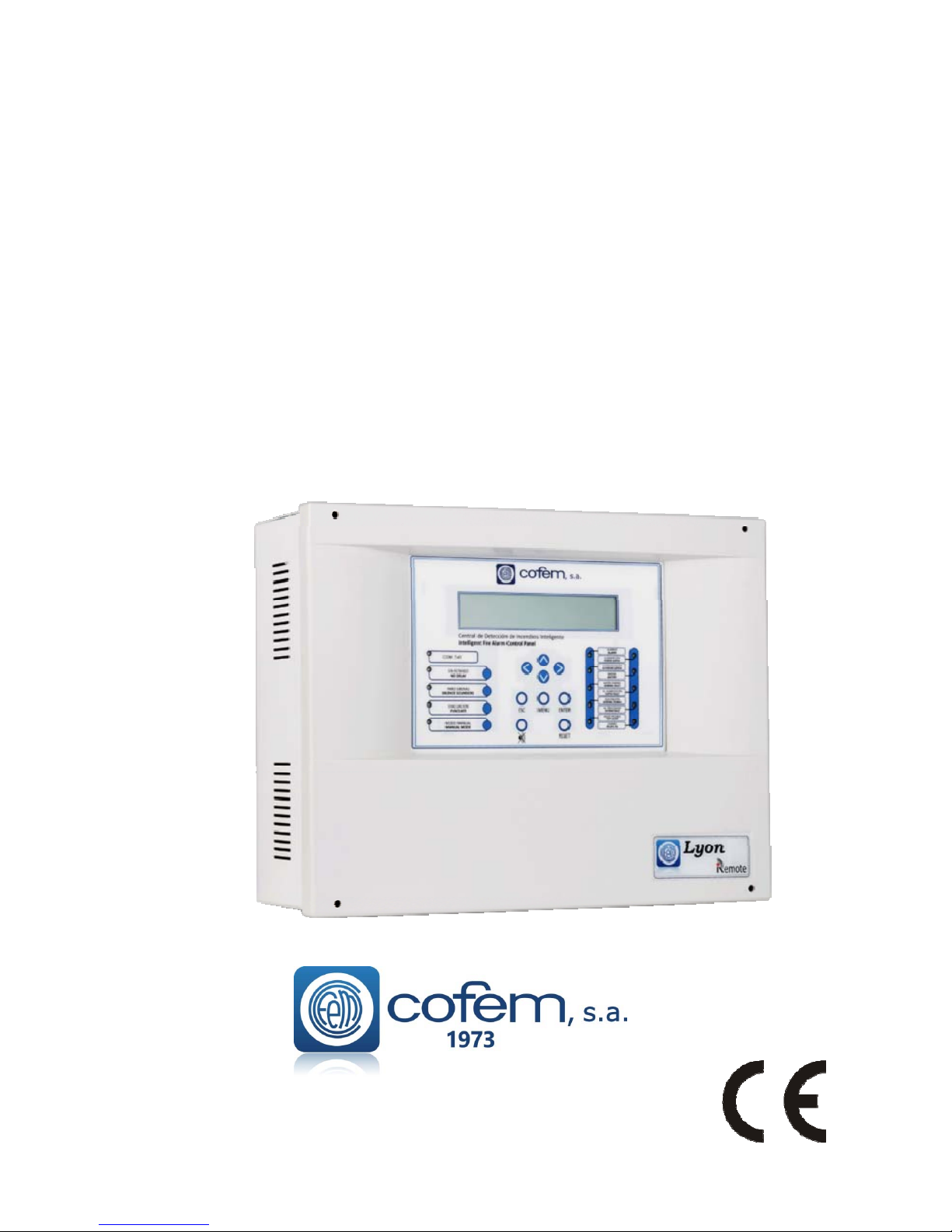
Digital fire detection control panel
Lyon
Page 2

Digital fire detection control panel
LYON
FIRE PROTECTION MANUFACTURER
Ctra. de Molins de Rei a Rubí, Km. 8,4 - 08191 RUBÍ (Barcelona) ESPAÑA.
1.- System description .................................................................................................................................................. 7
1.1.- Introduction ...................................................................................................................................................... 7
1.2.- Principle of operation ....................................................................................................................................... 7
1.3.- Characteristics .................................................................................................................................................. 8
1.4.- Composition of the control panel ..................................................................................................................... 8
1.5. - Loop Elements Capacity .................................................................................................................................. 9
1.5.1.- Analogue sensors ..................................................................................................................................... 13
1.5.1.1.‐Analoguesmokesensors(A30XHA&A30XHA‐S).............................................................................13
1.5.1.2.‐Analoguetemperaturesensor(A30XTA).........................................................................................14
1.5.1.3.‐Analoguemulti‐sensor(A30XHTCO)................................................................................................15
1.5.2.- Analogue alarm Manual Call Point (PUCAY)......................................................................................... 17
1.5.3. - Modules .................................................................................................................................................. 18
1.5.3.1‐Masterdetectionmodule(KMAY)....................................................................................................18
1.5.3.2‐Masterrelaysmodule(MDA1Y)
........................................................................................................19
1.5.3.3‐Masterrelaymodule(MDA2Y)..........................................................................................................19
1.5.3.4‐Technicalsignalsmodule(MSTAY)....................................................................................................21
1.5.3.5‐Loopisolator(KABY)..........................................................................................................................22
1.5.3.6‐Addressablesounder(SIRAY/SIRAYL/SIRAY+BSLC).......................................................................23
1.5.3.7‐Masterrelayandtechnicalsignalsmodule(MYOA).........................................................................25
1.5.4.- Repeaters .................................................................................................................................................. 26
1.5.4.1.‐Installation........................................................................................................................................26
1.5.4.2.Operationand
Configuration............................................................................................................26
1.5.4.3.‐Repeatermenus...............................................................................................................................27
1.5.5.- Control panels network ............................................................................................................................ 29
1.5.5.1.‐Installation........................................................................................................................................29
1.5.5.2.‐Operationandconfiguration............................................................................................................30
1.5.5.3.‐Controlpanelsnetworkmenu..........................................................................................................30
1.6.- Accessories. .................................................................................................................................................... 32
1.6.1.- PC Keyboard ............................................................................................................................................ 32
1.6.2.- PC based configuration software. ............................................................................................................ 32
2.- Installation ............................................................................................................................................................. 32
2.1.- Control panel installation. ............................................................................................................................... 32
2.2.- Lyon analogue system connection .................................................................................................................. 33
DOCLYONING-ENE19
Page 3

Digital fire detection control panel
LYON
FIRE PROTECTION MANUFACTURER
Ctra. de Molins de Rei a Rubí, Km. 8,4 - 08191 RUBÍ (Barcelona) ESPAÑA.
Tlf.: +34 935 862 690 - Fax:+34 936 999 261 - [email protected] - www.cofem.com 3
2.2.1.- Electrical supply network. ....................................................................................................................... 33
2.2.2.- Loop driver............................................................................................................................................... 34
2.2.3.- Power supply auxiliary outputs and charging of power source batteries. ................................................ 35
2.3.- Components. ................................................................................................................................................... 36
2.3.1.- Batteries. .................................................................................................................................................. 36
2.3.2.- Connection schematic of a typical loop. .................................................................................................. 36
2.3.3.- Sounder and controls with relays. ............................................................................................................ 38
2.3.3.1.‐Connectionoftheinternaltwotone24VSounder(SIR‐24B/SIR‐24BL)..........................................38
2.3.3.2.‐Connectionofthenon‐flashinginternal24VSounder(SIR24P)......................................................38
2.3.3.3.‐Connectionoftheflashinginternal24VSounder(SIR24F)..............................................................39
2.3.3.4.‐Connecting
theexternal24Valarmbox(CAE‐PL)...........................................................................39
2.4.- Accessories. .................................................................................................................................................... 40
2.4.1.- PC keyboard ............................................................................................................................................. 40
2.4.2.- Computer. ................................................................................................................................................ 41
3.- Operation and configuration.................................................................................................................................. 43
3.1.- Description of the front panel. ........................................................................................................................ 43
3.1.1.- Keypad. .................................................................................................................................................... 43
3.1.2.- Light indicators. ....................................................................................................................................... 43
3.1.3.- Screen. ...................................................................................................................................................... 44
3.2.- Access levels. ................................................................................................................................................. 44
3.2.1.- Level 1 access. ......................................................................................................................................... 47
3.2.1.1.‐Activationofthecontrolpanel........................................................................................................47
3.2.1.2.Incidentandanomalydisplay............................................................................................................49
3.2.1.3.‐Movingthroughincidents................................................................................................................51
3.2.1.4.‐Lookupincidents.............................................................................................................................
51
3.2.1.5.‐Silencebuzzer...................................................................................................................................52
3.2.2. - Level 2 access. ........................................................................................................................................ 52
3.2.2.1.‐Accesscode.....................................................................................................................................52
3.2.2.2.‐Frontpanelkeypad...........................................................................................................................52
3.2.2.3.‐Resetevents.....................................................................................................................................52
3.2.2.4.‐Monitor............................................................................................................................................52
3.2.2.5.‐Activate/Deactivatelogicalrelays..................................................................................................53
3.2.2.6.‐Activate/Deactivategeneralrelays................................................................................................53
3.2.2.7.‐Systemconfiguration.
......................................................................................................................53
3.2.2.8.‐Enable/Disableelementsandzones...............................................................................................53
3.2.2.9.‐Systemtest.......................................................................................................................................53
3.2.2.10.‐Welcomemessage.........................................................................................................................54
3.2.2.11.‐Generalreset.................................................................................................................................54
Page 4

Digital fire detection control panel
LYON
FIRE PROTECTION MANUFACTURER
Ctra. de Molins de Rei a Rubí, Km. 8,4 - 08191 RUBÍ (Barcelona) ESPAÑA.
3.2.2.12.‐Reviewhistory...............................................................................................................................54
3.2.3- Level 3 access. .......................................................................................................................................... 55
3.2.3.1‐Accesscode.......................................................................................................................................55
3.2.3.2.‐Labelelements.................................................................................................................................55
3.2.3.3.‐Configure..........................................................................................................................................55
3.2.3.3.1.‐Loopconfiguration....................................................................................................................55
3.2.3.3.2.‐Configurelogicalrelays.............................................................................................................56
3.2.3.3.3.‐Configurealarmzones...............................................................................................................57
3.2.3.3.4.‐Configureelementsensitivity....................................................................................................57
3.2.3.3.5.‐Additionalpasswords................................................................................................................57
3.2.3.3.6.‐Configure
auto‐evacuation........................................................................................................57
3.2.3.3.7‐AddedDelaySetup.....................................................................................................................58
3.2.3.3.8‐FastTriggerZone........................................................................................................................58
3.2.3.3.9‐SendZonestoRepeaters............................................................................................................58
3.2.3.4.‐Updatedateandtime......................................................................................................................58
3.2.3.5.‐Day/Nighttimes...............................................................................................................................58
3.2.3.6.‐Putintotest/normalmode..............................................................................................................58
3.2.3.7‐LedON/OFF.....................................................................................................................................
59
3.2.3.8.‐Languagemenu................................................................................................................................59
3.2.3.9.‐Communications..............................................................................................................................59
3.2.3.10.‐StopSounderFunction...................................................................................................................61
4.- Set-up. ................................................................................................................................................................... 61
4.1.- Prior verifications. .......................................................................................................................................... 61
4.2.- Supply ............................................................................................................................................................. 62
4.3.- Loops and relays ............................................................................................................................................. 62
4.4.- Faults .............................................................................................................................................................. 63
Annex 1: Use of the Control Panel LYON / C-LYON / ZAFIR system .................................................................... 69
1. What is a control panel LYON / C_LYON /ZAFIR SYSTEM? ........................................................................ 69
2. Front panel of the system .................................................................................................................................... 69
3. What happens if the buzzer sounds? ................................................................................................................... 69
4. Checking the incident ......................................................................................................................................... 69
5. Evacuation .......................................................................................................................................................... 70
6. SILENCE SIRENS ............................................................................................................................................. 70
7. RESET EVENTS ................................................................................................................................................ 70
Annex 2: Elements configuration Lyon / C-Lyon / Zafir ........................................................................................... 71
1. Introduction ......................................................................................................................................................... 71
2. Keypad access ..................................................................................................................................................... 71
3. Configuration of points in a loop ........................................................................................................................ 72
Page 5

Digital fire detection control panel
LYON
FIRE PROTECTION MANUFACTURER
Ctra. de Molins de Rei a Rubí, Km. 8,4 - 08191 RUBÍ (Barcelona) ESPAÑA.
Tlf.: +34 935 862 690 - Fax:+34 936 999 261 - [email protected] - www.cofem.com 5
3.1. System Programming ................................................................................................................................... 73
3.2. Configure ...................................................................................................................................................... 73
3.3. Configure Loop ............................................................................................................................................ 73
3.4. Loop Configuration ...................................................................................................................................... 73
3.5. Assign a number to Point ............................................................................................................................. 74
4. Programming verification process ...................................................................................................................... 74
5. Configure Zones ................................................................................................................................................ 74
6. Replacing a loop element .................................................................................................................................... 75
Page 6
Digital fire detection control panel
LYON
FIRE PROTECTION MANUFACTURER
Ctra. de Molins de Rei a Rubí, Km. 8,4 - 08191 RUBÍ (Barcelona) ESPAÑA.
6
CERTIFICATION
Lyon control panels are supplied with the following material:
2 end of line resistances 4K7 2W 5%
2 diodes DBY252
4 fuses: 1 A, 2 A, 4 A y 8 A.
0099
,
Crta. Molins de Rei a Rubí, Km 8,4 CP 08191 Rubí, Barcelona (España)
09 / 10
0099/CPR/A74/0074 – 0099/CPR/A74/0100
EN 54-2
Equipo de control e indicación para sistemas de detección y
alarma de incendios en edificios
Control and indicating equipment for fire detection and alarm
systems in buildings
“CDAn Lyon”
Comportamiento frente a incendios
Performance under fire condition
Cumple/ Passed
Intervalo de respuesta (tiempo de respuesta al fuego)
Response delay (response time to fire)
Cumple/ Passed
Seguridad Operacional
Operational reliability
Cumple/ Passed
Duración de la seguridad operacional y retardo a la respuesta;
resistencia a la temperatura
Durability of operational reliability, Temperature resistance
Cumple/ Passed
Duración de la seguridad operacional y retardo a la respuesta;
resistencia a la vibración
Durability of operational reliability Vibration resistance
Cumple/ Passed
Duración de la seguridad operacional y retardo a la respuesta;
estabilidad eléctrica
Durability of operational reliability: electrical stability
Cumple/ Passed
Duración de la seguridad operacional y retardo a la respuesta;
resistencia a la humedad
Durability of operational reliability: humidity resistance
Cumple/ Passed
EN 54-4
Equipo de suministro de alimentación de sistemas de
detección y alarma de incendios en edificios
Power supply equipment for fire detection and alarm systems
in buildings
“CDFA-01”
Comportamiento de suministro de alimentación/
Performances of Power Supply
Cumple/ Passed
Fiabilidad en el funcionamiento/
Operational reliability
Cumple/ Passed
Duración de la seguridad operacional y retardo a la respuesta;
resistencia a la temperatura
Durability of operational reliability, Temperature resistance
Cumple/ Passed
Duración de la seguridad operacional y retardo a la respuesta;
resistencia a la vibración
Durability of operational reliability Vibration resistance
Cumple/ Passed
Duración de la seguridad operacional y retardo a la respuesta;
estabilidad eléctrica
Durability of operational reliability: electrical stability
Cumple/ Passed
Duración de la seguridad operacional y retardo a la respuesta;
resistencia a la humedad
Durability of operational reliability: humidity resistance
Cumple/ Passed
Page 7

Digital fire detection control panel
LYON
FIRE PROTECTION MANUFACTURER
Ctra. de Molins de Rei a Rubí, Km. 8,4 - 08191 RUBÍ (Barcelona) ESPAÑA.
Tlf.: +34 935 862 690 - Fax:+34 936 999 261 - [email protected] - www.cofem.com 7
1.- System description
1.1.- Introduction
The Analogue Fire detection Control Panel LYON is EN54-2 and EN 54-4 standard certified
according to the latest CE directives and can succesfully overcome difficult environmental conditions,
electrical interference, electromagnetic radiate upsets, vibrations, etc.
The Analogue Detection System represents the most modern technology in fire detection and
constitutes a natural evolution from the Identifiable Detection System towards equipment that not only is
able to identify the element that produces the alarm (sensor or button), but that also allows for the total
configuration of detection parameters (alarm levels, sensitivity,…) as well as the adaptation of the set-up to
the environmental conditions and the dirtiness of the sensor.
In the Cofem Analogue Detection System, the loop elements (sensors, manual call points, relay
modules, masters, analogue sounders and technical indicator modules) are auto-identifiable, in other words,
all of them can be installed with no need for prior manual encoding, facilitating enormously the assembly of
and subsequent modifications to the installation.
1.2.- Principle of operation
The Analogue Detection System is based on the measurement and transmission of the instant value
of the monitored magnitude (smoke, temperature or monoxide concentration), for their subsequent
processing in the control panel, which will consider the alert or standby status of the sensor.
The temperature, the smoke concentration and the amount of monoxide are sent through the
corresponding sensor in electrical voltages related to the measured magnitude.
After an adaptation process, an optimal relationship between the measured magnitude and the
electrical voltage is obtained.
Each sensor incorporates a microprocessor responsible for the digitisation of the analogue value read
in the sensor, for transmission of this value to the control panel and for identification of the sensor.
The main difference between the conventional and analogical detection systems lies in that for the
former the Voltage delivered by the transducer is compared with a predetermined and fixed threshold
(V
alarm
), obtaining from that comparison the system in standby or system in alarm status.
In the Digital Detection System, on the contrary, the value given by the transducer is constantly
recorded and processed, being possible to act on the detection parameters, as well as, for example, the alarm
threshold.
With this type of system, not only we can vary the sensitivity of the sensor, but we can even adapt
the sensitivity to the environmental conditions.
Each sensor on the Cofem Analogue Detection System transmits its analogue value to the control
panel with a regularity of less than 10 seconds. The control panel gathers the readings from each sensor and
determines the status thereof according to these instant readings, any previous readings (history), the preprogrammed parameters and on the decision algorithm.
Note: Within the detection and fire alarm systems, there are 2 different technologies. In the
CONVENTIONAL SYSTEM, the detector or the alarm call point is causing alarm in the control panel. In
the ADDRESSABLE SYSTEM, the detector, the alarm call point or the module, is the device which
communicates the value of reading or state to the control panel, and this one processes the alarm state.
Page 8

Digital fire detection control panel
LYON
FIRE PROTECTION MANUFACTURER
Ctra. de Molins de Rei a Rubí, Km. 8,4 - 08191 RUBÍ (Barcelona) ESPAÑA.
1.3.- Characteristics
Base control panel configurable and expandable from 1 to 20 loops.
Allows 199 connection elements per loop.
All the loop elements are monitored, except the KABY loop isolator.
Capacity for up to 199 configurable relays.
Enables programming of 99 zones.
File that stores up to 4095 events with date and time
Monitored delayable general siren output identified as “S1 SIRENA” (sounder).
Voltage-free non-monitored alarm output identified as “S2 ALARMA” (Alarm).
Non-monitored delayable free voltage general failure output identified as “S3 AVERIA” (Fault).
Evacuation button.
Backlit LCD display of 4 lines and 40 characters.
Incorporates Spanish, English, French, Portuguese, etc, languages.
Configurable and manageable through PC I-Link software.
Allows connection to an external keyboard (PC standard – PS2).
Allows connection of up to 15 repeaters and 15 network control panels.
MODBUS (See specific manual of this functionality).
Contact ID (See specific manual of this functionality).
Cofem REMOTE.
Size: 424 x 330 x 140 mm
IP30.
Certified and CE marked according to EN 54-2 and EN 54-4 Standard.
1.4.- Composition of the control panel
Backlit LCD display of 4 lines and 40 characters.
Keyboard made up of 13 keys that form two groups; one where the menu handling keys can be
found and the other where specific control panel functions may be performed.
15 LEDs that enable quick viewing of the control panel status (Supply, Mode of operation,
Alarms and Failures).
Communications port: USB 2.0.
Access to the interior of the control panel by means of a key.
Power supply: independent module responsible for controlling the Voltage of the primary 30V
supply that supplies the other boards. In this there are: protection fuses, 30V output, battery
connection terminals, relay outputs:
S1 SIRENA (Sounder): delayable monitored relay.
S2 ALARMA (Alarm): Voltage-free relay.
S3 AVERIA (Failure): free voltage delayable relay
Power supply controller: card that manages all the power supply information, that is to say,
monitors and controls the outputs and inputs of the power supply to subsequently send the
information to the CPU or to execute the instructions that it receives from the latter. The
communication is performed via RS485.
System managed by microprocessor.
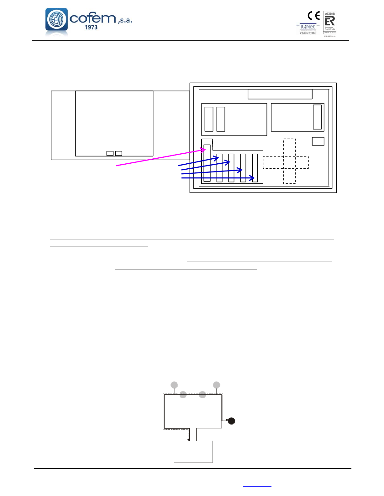
Loop controller: modular cards incorporated into the rack system connected to the control panel
back panel (circuit with connectors and guides from the top left part). This card manages the
information corresponding to 4 loops, that is to say, for every 4 loops we must have a loop
controller. The communication between controller and the CPU are performed by means of
RS485.
Loop driver: modular cards incorporated in the rack system, located inside the box and
connected to its corresponding loop controller by means of a flat 26 strand cable. These are
configured as 1 or 2 loops depending on the number of loops of the control panel. The driver of
Page 9
Digital fire detection control panel
LYON
FIRE PROTECTION MANUFACTURER
Ctra. de Molins de Rei a Rubí, Km. 8,4 - 08191 RUBÍ (Barcelona) ESPAÑA.
Tlf.: +34 935 862 690 - Fax:+34 936 999 261 - [email protected] - www.cofem.com
9
loops 1 and 2 will be plugged into the lower connector of the loop controller, and the driver of
loops 3 and 4 will be connected to the upper connector of the loop controller.
In a single box we will be able to connect 2 loop controllers and their 4 corresponding loop
drivers. Therefore for configurations in excess of 8 loops we will need two boxes.
Figure 1. Layout of circuits in the control panel
1.5. - Loop Elements Capacity
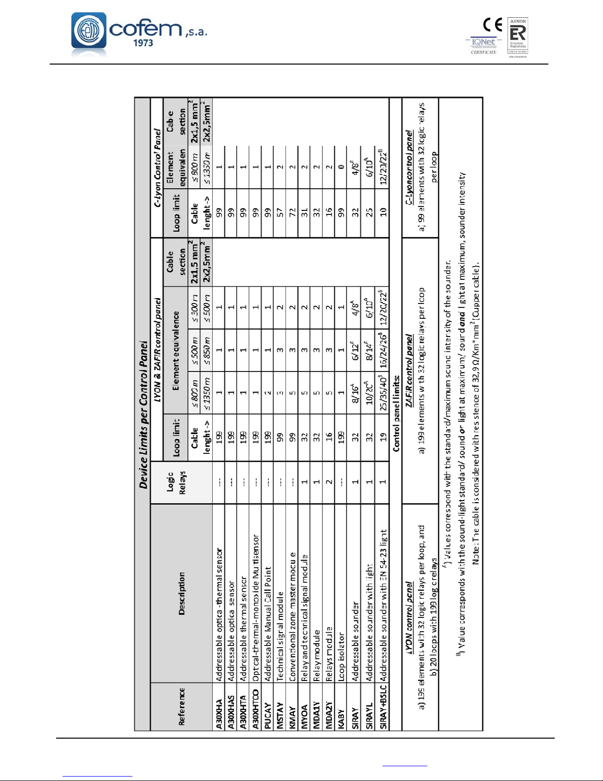
The number of devices that it is possible to connect to the loop is calculated of precise form by the software
of loop elements capacity calculation.
When it is not feasible to use the previous software, it can be used next table to obtain approximate capacity
,
which, in a general way, gives values under the real performances of the system
.
For this motive, it is necessary to check real capacity of the system by means of the loop elements capacity
calculation software when results of using table approximation doesn’t allow to satisfy the installation
necessities, as the real capacity of the system can be higher than expected by the tables.
To calculate the capacity of the system, it should take into account two parameters: The number equivalent
elements connected in the loop (shown in the table depending on cable length, cable section and control
panel model) and number of logic relays (also shown in the table).
The system will work properly when it meets the limits establieshed in the device limit per control panel.
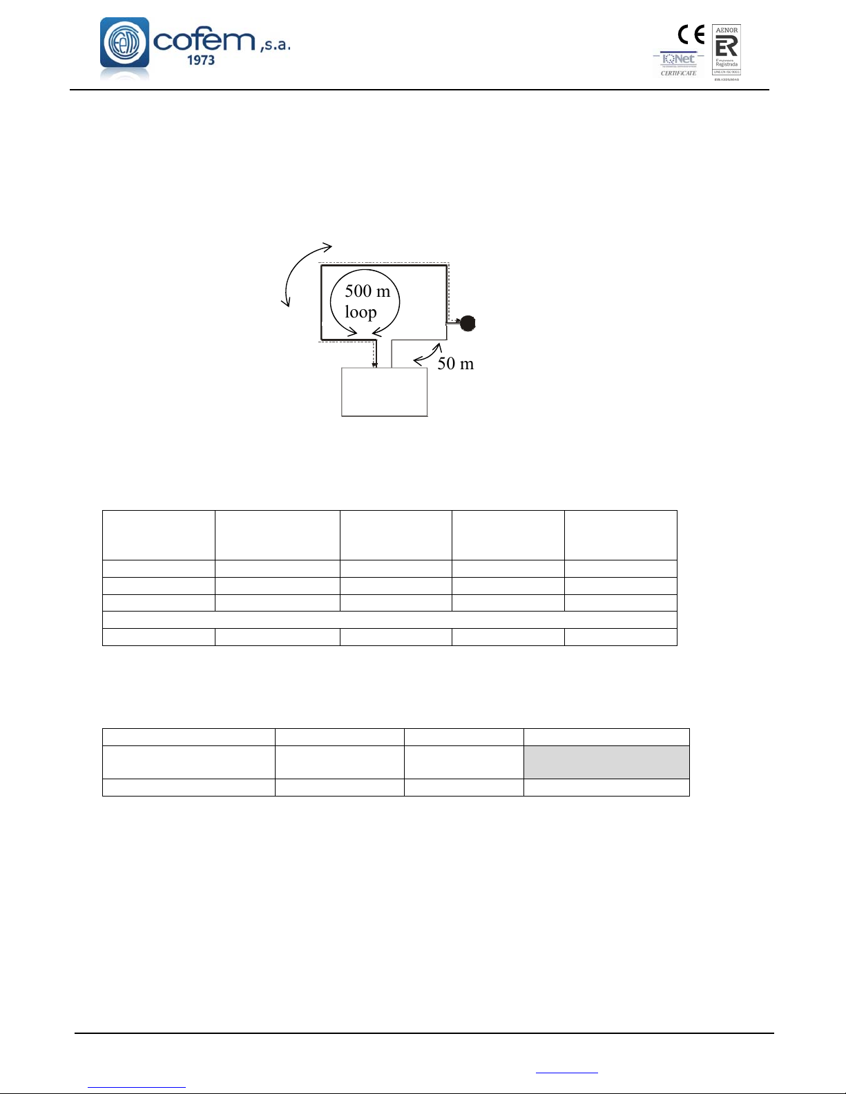
For the system, the cable length is the length of the loop cable from the nearest element in the loop to the
control panel, measure to the other side of the control panel loop input/output. That means length cable is
always less that the cable length loop as it is shown in the figure.
CPU
Switching Pow er Supply
Power Supply
BackPanel
Loop
Controller
Loop
Driver
REMOTE
Card
USB
PS2
Page 10
Digital fire detection control panel
LYON
FIRE PROTECTION MANUFACTURER
Ctra. de Molins de Rei a Rubí, Km. 8,4 - 08191 RUBÍ (Barcelona) ESPAÑA.
The cable material for the table is Cu with 41 Ω* mm2/Km, as it is stated in the corresponding note.
Page 11
Digital fire detection control panel
LYON
FIRE PROTECTION MANUFACTURER
Ctra. de Molins de Rei a Rubí, Km. 8,4 - 08191 RUBÍ (Barcelona) ESPAÑA.
Tlf.: +34 935 862 690 - Fax:+34 936 999 261 - [email protected] - www.cofem.com
11
EXAMPLE OF CALCULATION
An installation requires 136 A30XHAS sensors, 17 PUCAY manual call points and 18 addressable
sounders SIRAY with standard sound level.
It is known that installation requires 1 loop cable of 500 m with 2x1,5 mm
2
section, where the
nearest device to control panel is 50 m.
First, it is made calculation using table of device limits per control panel, with a Lyon control panel,
2x1,5 mm
2
section, and cable lenght ≤ 500 m (for this case, cable lenght is 450 m). Following table is
obtained:
Devices in
installation
Elements
equivalence
according to table
Elements
consumption
Relays
equivalence
according to table
Relays
consumption
136 A30XHAS 1 136 - 0
17 PUCAY 1 17 - 0
18 SIRAY 6 108 1 18
TOTAL
171 Elements - 261 Elements - 18 Relays
Comparing these results with the boundaries of the control panel at the device limits of control panel,
we get:
Control panel Lyon Calculation
RESULTS
Loop elements
consumption
199 261
199 < 261 → EXCESS
Relays limits 32 18 32 ≥ 18 → Ok
The limit of loop elements consumption of control panel is 199 elements. Calculation gets 261
elements, therefore, capacity of the loop is exceed.
Now, calculation will be accurately made by the software of loop elements capacity calculation.
500 m
loop
50 m
450 m
Page 12
Digital fire detection control panel
LYON
FIRE PROTECTION MANUFACTURER
Ctra. de Molins de Rei a Rubí, Km. 8,4 - 08191 RUBÍ (Barcelona) ESPAÑA.
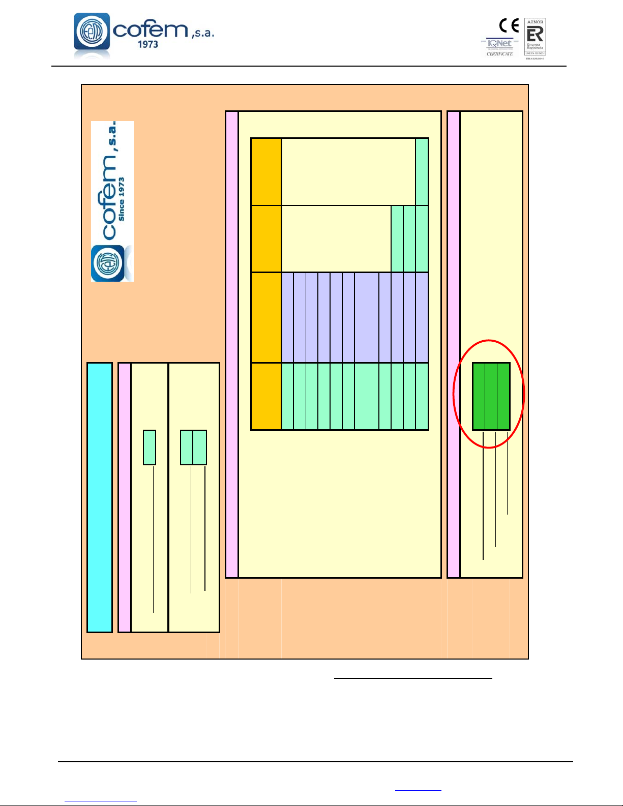
It is shown the results. Loop of control panel LYON perfectly support this configuration instead of
calculation by table of device limits per control panel were excess of capacity.
This example clearly states that it is important to check results by software of loop elements capacity
calculation when it is obtained excess performances by using the table of device limits per control panel.
It also could have achieved this result using the software directly.
LYON
450 m
1,5
mm
2
NºElements/Nº
Equipos
Model/
Modelo
SounddB/
SonidodB
PowerLight/
PotenciaLuz
17 PUCAY
0 KMAY
0 MSTAY
0 MDA1Y
0 MDA2Y
0 MYOA
136
A30XHA/A30XHAS/
A30XTA/A30XHTCO
0 KABY
18 SIRAY Standard
0 SIRAYL Standard
0 (SIRAY+BSLC) Standard Standard
78,21%
171
18NºRelays/NºReles=
LOOPELEMENTSDATA/DATOSELEMENTOSBUCLE
RESULTS/RESULTADOS
LOOPLOAD/CARGADELBUCLE=
NºElements/NºElementos=
Cablesection/Seccióndelcable=
LOOPELEMENTSCAPACITYCALCULATION
CÁLCULODECAPACIDADDEELEMENTOSDELBUCLE
GENERALDATA/DATOSGENERALES
ControlPanelModel/ModeloCentral=
Wirelenght/Longituddelcable=
Page 13
Digital fire detection control panel
LYON
FIRE PROTECTION MANUFACTURER
Ctra. de Molins de Rei a Rubí, Km. 8,4 - 08191 RUBÍ (Barcelona) ESPAÑA.
Tlf.: +34 935 862 690 - Fax:+34 936 999 261 - [email protected] - www.cofem.com
13
1.5.1.- Analogue sensors
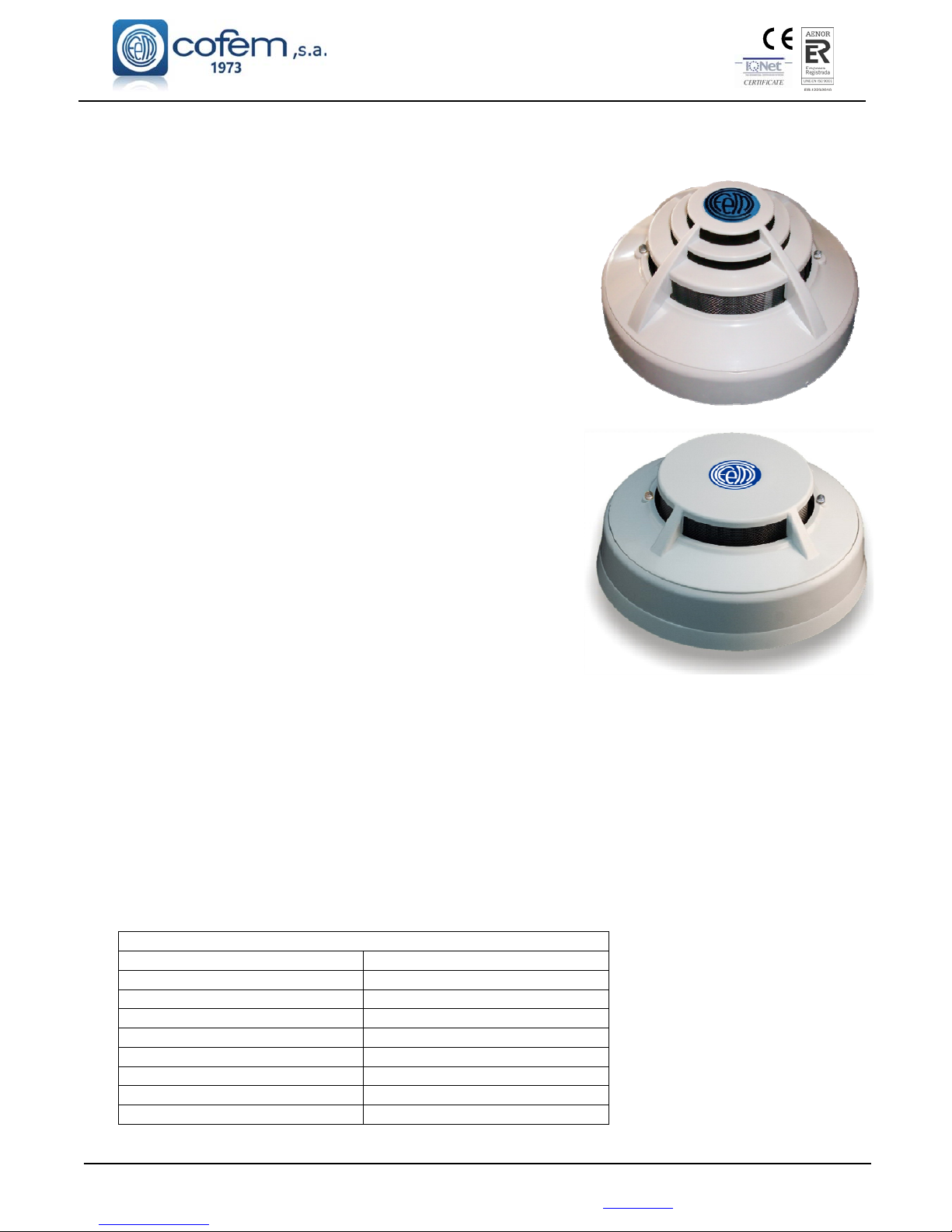
1.5.1.1.- Analogue smoke sensors (A30XHA & A30XHA-S)
The analogue smoke sensors measure the smoke particle
concentration by unit of volume present in the atmosphere. If we
designate by Y an un-dimensioned parameter proportional to the
smoke concentration, then Y will have to be close to zero, and will
be growing as the atmosphere is contaminated.
The implemented dynamic processing algorithms in the
control panel, use the Y
alarm
value as level for setting off the Alarm.
This preset level is at:
Y
alarm
= 40
This level can be manually modified from the control panel.
When the concentration of smoke exceeds the Alarm Level
(the average must exceed Y
alarm
) the alarm for the sensor is
activated.
Through the control panel, a level Y
dirty
(20) is set and when
this is exceeded the system warns us of the need to replace or repair
the sensor.
The Optical Smoke Sensor (A30XHA) is based on the
Tyndall effect created in an optical camera. The variation of the
electrical characteristics in the presence of combustion aerosols
makes it suitable as a smoke sensor.
The sensor element is formed by an optical camera provided
with an infrared emitter and receiver. In the absence of smoke the
intensity of infrared caught by the receiver is null, due to the
physical labyrinth created between the two. When smoke is present,
the infrared reflections from the particles of the same cause the
receiver to obtain a certain luminance intensity, (Voltage value proportional to the
level of obscuration), all of which is controlled by the microprocessor system.
This sensor has a thermistor, acting as a temperature sensor, triggering at 60ºC, considerably
augmenting its response to fire.
An optical smoke sensor without a thermal element is also available, with reference A30XHA-S.
The A30XHA and A30XHA-S are conformant with EN 54-7 with the conformity mark awarded by
AENOR.
The head and the base (interchangeable throughout the range of sensors) are made in thermal
resistant ABS.
The flashing of the red transparent LEDs indicates communication with the Control panel Lyon
system, and if they remain lit they indicate the alert status of the sensor.
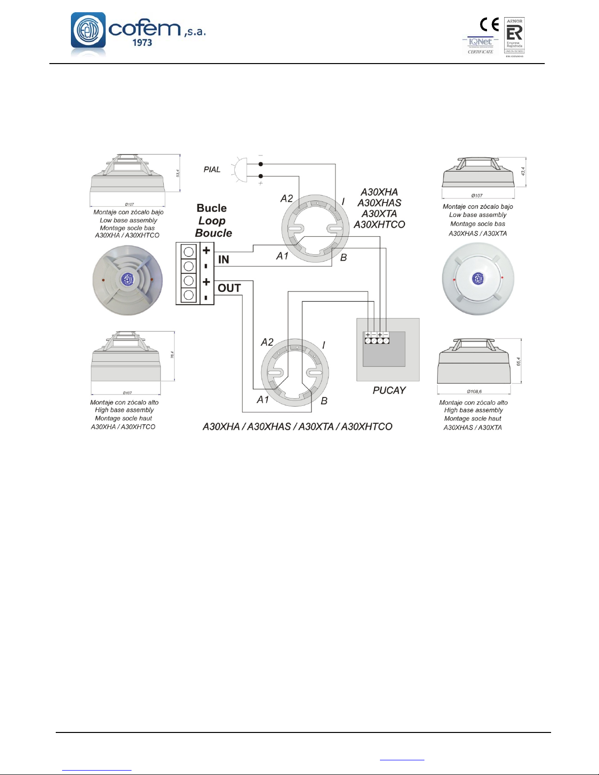
Connection is made according to figure 2.
Technical specifications A30XHA and A30XHA-S
Supply 24 – 35 V any polarity
Standby consumption 1 mA
Alarm consumption 5 mA
Indicator activation Double red LED
Remote indicator output Yes
Humidity 20% – 95% RH
Temperature -10º + 50ºC
Sensitivity According to EN 54-7
IP IP40
Sensor A30XHA
Sensor A30XHAS
Page 14
Digital fire detection control panel
LYON
FIRE PROTECTION MANUFACTURER
Ctra. de Molins de Rei a Rubí, Km. 8,4 - 08191 RUBÍ (Barcelona) ESPAÑA.
14
1.5.1.2.- Analogue temperature sensor (A30XTA)
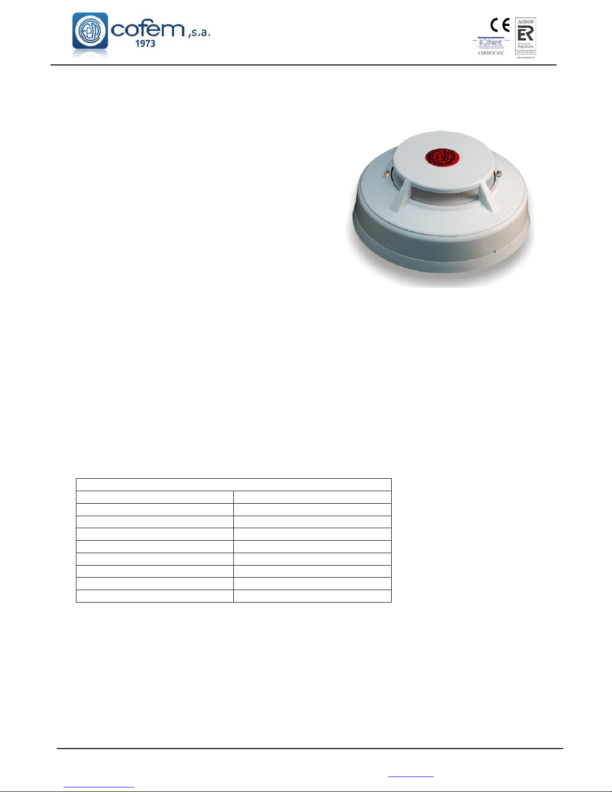
The Analogue Temperature Sensor (A30XTA) measures the room temperature, as well as its rate of
change.
When the ambient temperature experiences slow
rates of change (less than 1ºC / min), the Alarm level remains
constant to 60ºC. However, for fast variations in temperature
(above 1 ºC/min), the control panel uses an algorithm capable
of evaluating the rate of change of temperature, and of
adjusting the Alarm level to different gradients (rate of rise
detection of temperature). In this way, a fast variation causes
a decrease in the Alarm threshold, thereby accelerating the
detection.
The chosen degree of sensitivity will depend on the
room temperature of the place where each sensor is installed,
and in each case the alarm temperature will adapt to the
chosen degree.
Also in the detection of temperature confirmation by means of two consecutive readings is used (less
than 10 seconds), before activation of the Alarm.
The operation principle is based on the physical properties of an NTC. The variation in electrical
characteristics of the thermistor, due to the variation of the room temperature, is what enables its use as a
sensor element.
The measurement made by the sensor is converted in a Voltage value, which is digitized and
transmitted to the control panel.
The A30XTA is conforms to EN 54-5 with the mark of conformity with the regulations awarded by
AENOR with an A2R sensitivity degree.
The head and the base (interchangeable throughout the range of sensors) are made in thermal
resistant ABS.
The flashing of the red transparent LED indicates communication with the Control panel Lyon
system, and if they remain lit they indicate the alert status of the sensor.
Connection is made according to figure 2.
Technical specifications A30XTA
Supply 24 – 35 V, any polarity
Standby consumption 1 mA
Alarm consumption 5 mA
Indicator activation Double red LED
Remote indicator output Yes
Humidity 20% – 95% RH
Temperature -10º + 50ºC
Sensitivity According to EN 54-5
IP IP20
Page 15
Digital fire detection control panel
LYON
FIRE PROTECTION MANUFACTURER
Ctra. de Molins de Rei a Rubí, Km. 8,4 - 08191 RUBÍ (Barcelona) ESPAÑA.
Tlf.: +34 935 862 690 - Fax:+34 936 999 261 - [email protected] - www.cofem.com
15
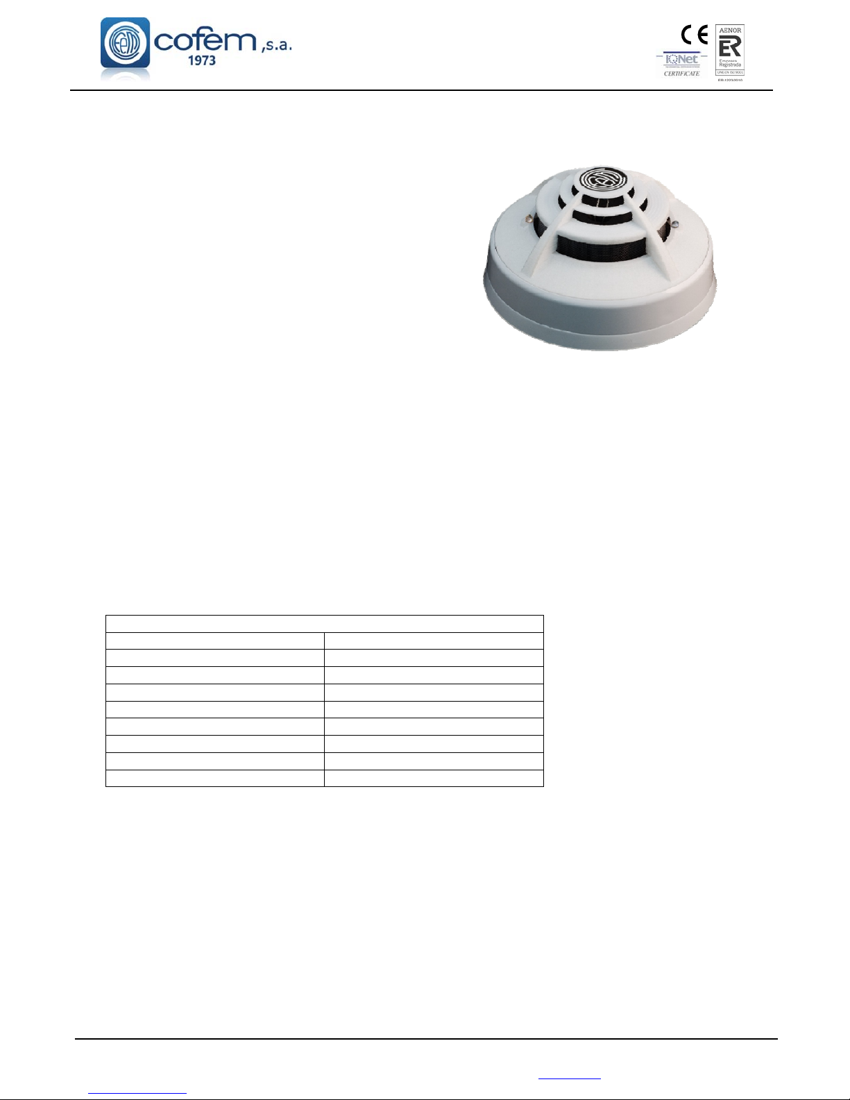
1.5.1.3.- Analogue multi-sensor (A30XHTCO)
The analogue multi-sensor A30XHTCO has three
detection types: monoxide, temperature and smoke.
The analogue multi-sensors is able to measure three
types of parameters so the control panel calculates an
average by means of a dynamic processing algorithm which
will vary with the three phenomena. This processing
algorithm will avoid false alarms to a great extent thanks to
the incorporation of the monoxide sensor.
The processing algorithm is able to compensate for
dirt on the optical camera by combining the measurements
of the three different sensors.
The sensor element is formed by an optical camera
provided with an infrared emitter and receiver. In the
absence of smoke the intensity of infrared captured by the receiver is null, due to the physical labyrinth
created between the two. When smoke is present, the infrared reflections from the particles of the same cause
the receiver to obtain a certain luminance intensity, (Voltage value proportional to the level of obscuration),
all of which is controlled by the microprocessor system.
In addition, it has a carbon monoxide sensor with a fast response in the presence of CO which is
present in the vast majority of fires.
Finally this sensor has a thermal probe, acting as a thermal sensor, triggering at 60ºC, considerably
increasing its response to fire.
The A30XHTCO is conformant with EN 54-7 with the conformity mark awarded by AENOR.
The head and the base (interchangeable throughout the range of sensors) are made in thermal
resistant ABS.
The flashing of the red transparent LEDs indicates communication with the Centralised Lyon
system, and if they remain lit they indicate the alert status of the sensor.
Connection is made according to figure 2.
Technical specifications A30XHTCO
Supply 24 – 35 V any polarity
Standby consumption 1 mA
Alarm consumption 5 mA
Indicator activation Double red LED
Remote indicator output Yes
Humidity 20% – 95% RH
Temperature -10º + 50ºC
Sensitivity According to EN 54-7
IP IP40
Page 16
Digital fire detection control panel
LYON
FIRE PROTECTION MANUFACTURER
Ctra. de Molins de Rei a Rubí, Km. 8,4 - 08191 RUBÍ (Barcelona) ESPAÑA.
Figure 2. Connection schematic A30XHA, A30XTA, A30XHTCO and PUCAY
Page 17
Digital fire detection control panel
LYON
FIRE PROTECTION MANUFACTURER
Ctra. de Molins de Rei a Rubí, Km. 8,4 - 08191 RUBÍ (Barcelona) ESPAÑA.
Tlf.: +34 935 862 690 - Fax:+34 936 999 261 - [email protected] - www.cofem.com
17
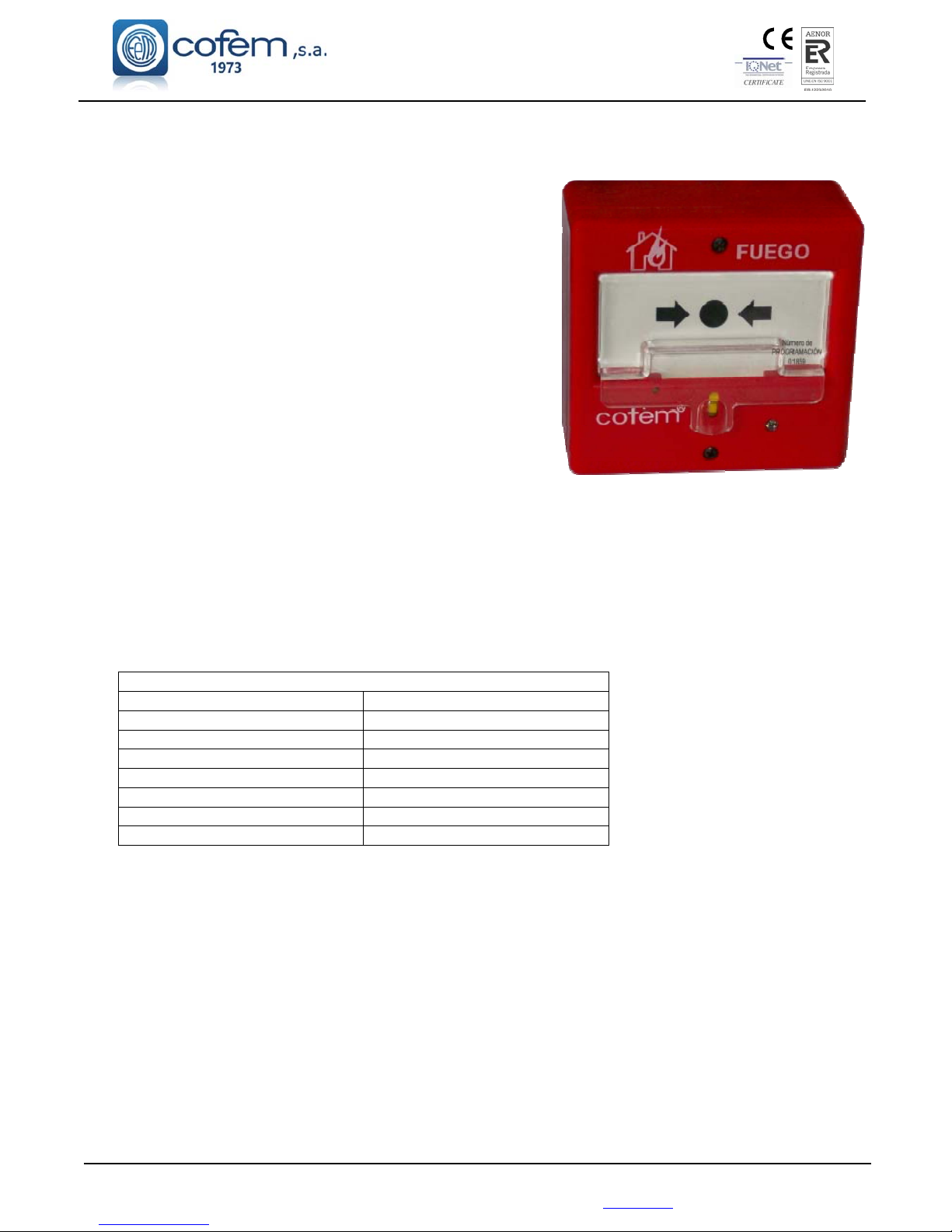
1.5.2.- Analogue alarm Manual Call Point (PUCAY)
The re-settable Analogue and Addressable manual call
point (with short-circuit isolator) incorporates an action indicator
(LED) which is illuminated in the case of being manually
activated (alarm).
The flashing of the transparent red LED indicates
communication with the Control panel Lyon system, and if it
remains on it indicates the alert status of the button.
There is a version “PUCAYEXT” that it is computed by
control panel as the activation of 2 simultaneous devices. In this
way, crossed relay L and crossed relay SL can be trigged directly
when you push this PUCAYEXT. From loop device capacity,
PUCAYEXT version is considered as a PUCAY.
The connection is made according to figure 2.
The PUCAY is conformant with EN 54-11 with the conformity mark awarded by AENOR.
Note: To determine the number of PUCAY it can be installed, consult the devices limit per
control panel table (Chapter 1.5)
Technical specifications PUCAY
Supply 24 – 35 V with polarity
Standby consumption 1 mA
Alarm consumption 5 mA
Indicator activation red LED
Remote indicator output No
Humidity 20% – 95% RH
Temperature -10º + 50ºC
IP IP50
Page 18
Digital fire detection control panel
LYON
FIRE PROTECTION MANUFACTURER
Ctra. de Molins de Rei a Rubí, Km. 8,4 - 08191 RUBÍ (Barcelona) ESPAÑA.
1.5.3. - Modules
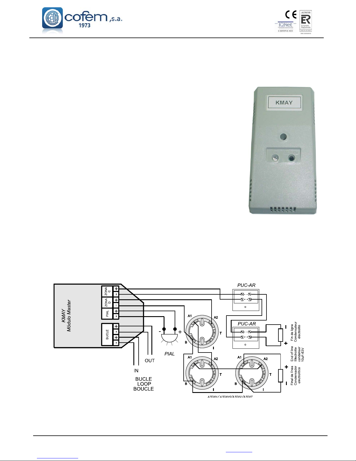
1.5.3.1- Master detection module (KMAY)
Microprocessed analogue and addressable device (with short-circuit isolator) installed as another
element inside the loop.
This is a device that allows connecting conventional detectors and/or
manual call point inside an analogue fire detection system, realising the interface
function between the analogue detection system and the conventional one.
In the “Zona C” terminal, a maximum of 10 conventional call points can
be installed. In the “Zona D” terminal, it is allowed 20 temperature detectors
(A30XT, A30XV) or 15 elements between conventional smoke detectors
(A30XH, A30XHS) and manual call points. Both terminals are monitored by an
end of line capacitor, 10 µF/63V. In this way, it is indicated an open line, crossed
line, alarm detector or alarm manual call point status.
The flashing of the transparent red LED indicates communication with
the control panel, and if it remains on it indicates the alarm status of a detector or
manual call point connected to this module.
This module has an output for activation of a remote indicator which will
be activated when alarm status is reached. The Master Detection Module takes
the power supply from the loop.
The Master Detection Modules is placed in a rectangular, heat-resistant ABS box.
The KMAY is conformant with EN 54-18 with the conformity mark awarded by AENOR.
Connection is made according to figure 3.
Note: To determine the number of KMAY it can be installed, consult the devices limit per
control panel table (Chapter 1.5)
Figure 3. Connection schematic KMAY
Page 19
Digital fire detection control panel
LYON
FIRE PROTECTION MANUFACTURER
Ctra. de Molins de Rei a Rubí, Km. 8,4 - 08191 RUBÍ (Barcelona) ESPAÑA.
Tlf.: +34 935 862 690 - Fax:+34 936 999 261 - [email protected] - www.cofem.com 19
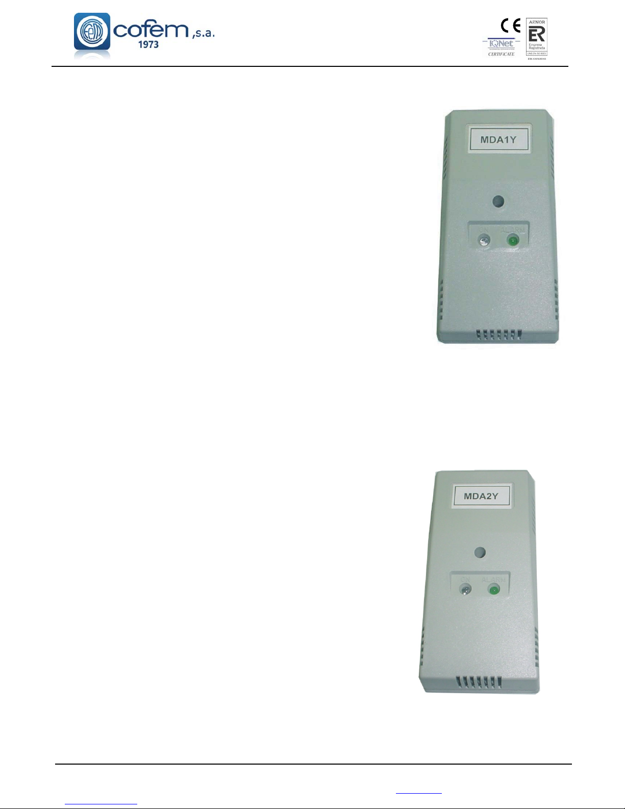
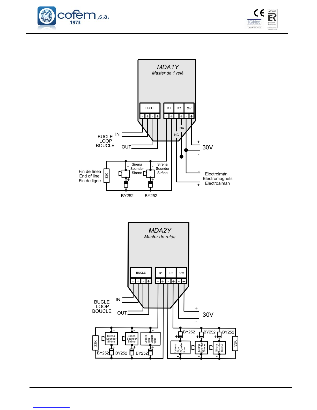
1.5.3.2- Master relays module (MDA1Y)
Microprocessed analogue and addressable devices (with short-circuit
isolator) installed as another element inside the loop.
The Modules take the power supply from the loop, but they require an
auxiliary 30V supply to give the necessary energy to the devices controled by
the relays. They monitor the presence of Voltage in the auxiliary supply line of
30V and in the output of the monitored relays. The Module is protected by 0.9
A resettable fuse and each monitored output by 0,5 A. The flashing of the
transparent red LED indicates communication with the Lyon system.
Illumination of the green LED indicates the actuation of a relay.
The device is placed in a rectangular, heat-resistant ABS box.
This is a module with two relay outputs of simultaneous activation
(with a single function), not only in its type of application (sounder, switches
or crossed relay), but also in their timing and in the combination of sensors
that activate them. The R1 output relay is monitored with a line termination
resistance of 33KΩ, indicating the state of opened line or crossed line. The R2
output relay acts as a dry contact NO and NC, not monitored, which typical
application is the energising of the electromagnets of fire-resistant doors.
Considering the consumption produced across the system, it is recommended
installation of an External Power Supply when connecting more than 10 electromagnets altogether per
detection system.
The MDA1Y is conformant with EN 54-18 with the conformity mark awarded by AENOR.
Connection will be made according to figure 4.
Note: To determine the number of MDA1Y it can be installed, consult the devices limit per
control panel table (Chapter 1.5)
1.5.3.3- Master relay module (MDA2Y)
Microprocessed analogue and addressable devices (with short-circuit
isolator) installed as another element inside the loop.
The Modules take the power supply from the loop, but they require
an auxiliary 30V supply to give the necessary energy to the devices controled
by the relays. They monitor the presence of Voltage in the auxiliary supply
line of 30V and in the output of the monitored relays. The Module is
protected by 0.9 A resettable fuse and each monitored output by 0,5 A. The
flashing of the transparent red LED indicates communication with the Lyon
system. Illumination of the green LED indicates the actuation of a relay.
The device is placed in a rectangular, heat-resistant ABS box.
It is a module with two relay outputs of independent activation (two
functions), not only in their type of application (sounder, switches or crossed
relay), but also in their timing and in the combination of sensors that activate
them. In the standby state, the MDA2Y monitors both external line by means
of a 33 KΩ resistance, indicating the state of open line or crossed line.
The MDA2Y is conformant with EN 54-18 with the conformity
mark awarded by AENOR.
Connection will be made according to figure 5.
Note: To determine the number of MDA2Y it can be installed, consult the devices limit per
control panel table (Chapter 1.5)
Page 20
Digital fire detection control panel
LYON
FIRE PROTECTION MANUFACTURER
Ctra. de Molins de Rei a Rubí, Km. 8,4 - 08191 RUBÍ (Barcelona) ESPAÑA.
Figure 4. Connection Schematic
Figure 5. Connection Schematic
INPUT
Page 21
Digital fire detection control panel
LYON
FIRE PROTECTION MANUFACTURER
Ctra. de Molins de Rei a Rubí, Km. 8,4 - 08191 RUBÍ (Barcelona) ESPAÑA.
Tlf.: +34 935 862 690 - Fax:+34 936 999 261 - [email protected] - www.cofem.com 21
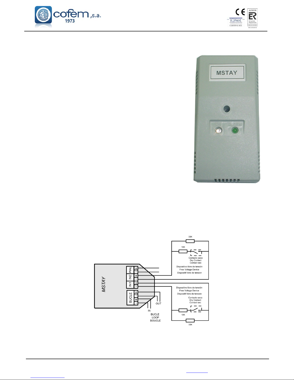
1.5.3.4- Technical signals module (MSTAY)
Microprocessed analogue and addressable devices (with short-circuit
isolator) installed as another element inside the loop.
It has two inputs to distinguish between the open or close state of a dry
contact connected in series with a 10 K resistor. In quiescent condition,
the contact has to be open, and in anomaly condition, the contact has to be
closed. In the first input (marked with IN1), the closed contact is detected
as an ALARM condition. In the second input (marked wit IN2), the closed
contact is detected as FAULT Warning condition. It is possible to associate
both inputs having an alarm and fault conditions information.
In the quiescent condition, the device supervises the electrical connection
through a 33 K resistor, which allows indication of open or closed
electrical connection status.
It is typically used to signal the status of other detection systems that
may exist, as for example, connection of flow sensors in the case of
sprinkler installations, end of travel in the case of fire-resistant doors,
elevators, level of deposits, etc.
The flashing of the transparent red LED indicates communication with the
Control Panel, and if it remains lit, it indicates an alarm status. The
illumination of the green LED indicates activation of one or both inputs.
This device has an output for connection to a remote action indicator, which is activated when in alarm status. This
element is electrical fed through the loop connection.
The MSTAY is conformant with EN 54-18 with the conformity mark awarded by AENOR.
Connection will be made according to figure 6.
Note: To determine the number of MSTAY it can be installed, consult the devices limit per control panel
table (Chapter 1.5)
IN1: Gives an alarm signal to the control panel
IN2: Gives a fault signal to the control panel
Figure 6. Connection schematic MSTAY
Page 22
Digital fire detection control panel
LYON
FIRE PROTECTION MANUFACTURER
Ctra. de Molins de Rei a Rubí, Km. 8,4 - 08191 RUBÍ (Barcelona) ESPAÑA.
22
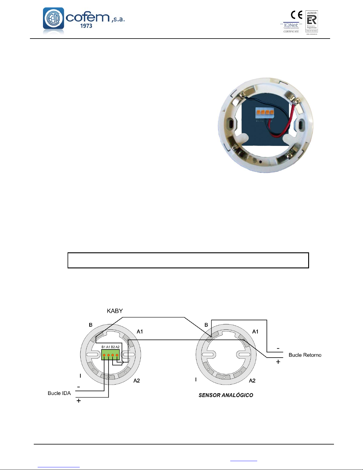
1.5.3.5- Loop isolator (KABY)
Microprocesed analogue element installed as another
element inside the loop (It is not addressable - There is not need to
configure this element).
This is a protection element that is connected into the
detection loop, with the aim of isolating stretches with
crossed line failures, and allowing therefore the rest of the loop
to operate normally.
It is supplied installed inside of a high base. This assembly
allows having it in the same place as the detector, making easy the
connection of the loop wiring.
The base has two stickers in the outer side with the word
“KABY” to allow easy recognition.
The element is feed from the loop connection.
The KABY is conformant with EN 54-17 with the conformity mark awarded by AENOR.
Connection will be made according to figure 7.
Note: To determine the number of KABY it can be installed, consult the devices limit per control
panel table (Chapter 1.5)
IMPORTANT The polarity in the KABY as shown in figure 7 must be observed.
Figure 7. Connection schematic KABY
Page 23
Digital fire detection control panel
LYON
FIRE PROTECTION MANUFACTURER
Ctra. de Molins de Rei a Rubí, Km. 8,4 - 08191 RUBÍ (Barcelona) ESPAÑA.
Tlf.: +34 935 862 690 - Fax:+34 936 999 261 - [email protected] - www.cofem.com 23
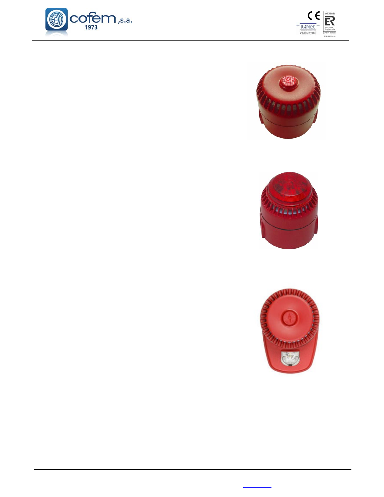
1.5.3.6- Addressable sounder (SIRAY / SIRAYL / SIRAY+BSLC)
Microprocessed addressable sounder (with short-circuit isolator)
installed as another element inside the loop.
This sounder is manufactured in red plastic ABS.
It is a module with a single programming function respecting the
timing and combination of sensors that activate it. This sounder is
configured as a relay being able to act as a sounder.
The SIRAYL and SIRAY+BSLC variants additionally emits light
signals, where, SIRAY+BSLC is EN 54-23 certified (visual alarm
devices). The fact that these sirens emit light specifically does not affect
the programming of control panel. For this reason, these devices are
programmed in the control panel as it was SIRAY.
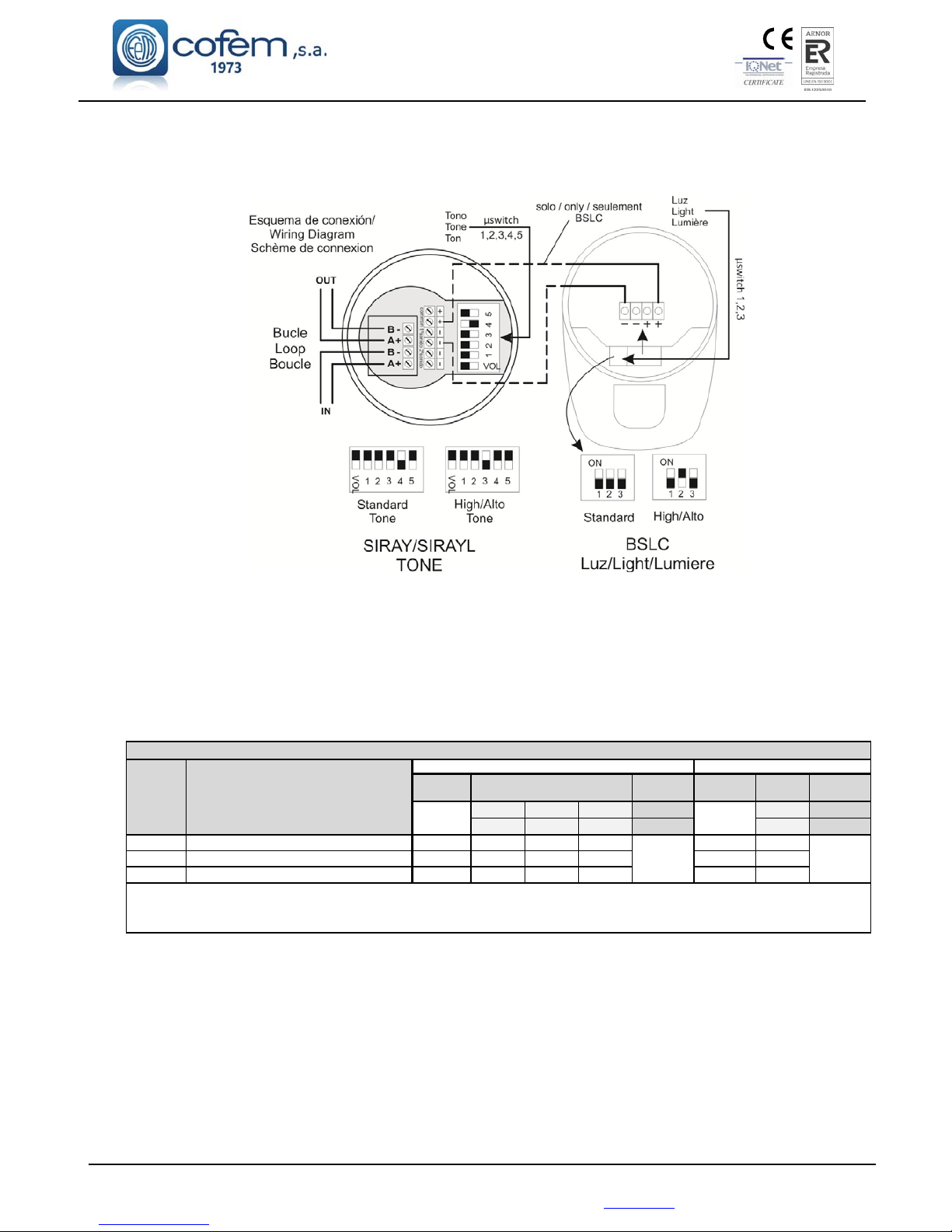
The standard configuration of the sound of the siren is shown in
Figure 8A according to EN 54-3 (sounder). In the same figure the
standard configuration of the light signal in the socket of the
SIRAY+BSLC siren according to EN 54-23 (visual alarm device) is
shown.
It is allowed to change the selection of the tone and light signal,
but this operation affects the power consumption of the sounder, and
therefore consumption elements equivalence of the device. Figure 8B is
a table showing equivalence to tone selections (standard 95-1m dB and
105 dB maximum sound intensity-1m) and visual signal (W-2,4-2,3/7,5).
Calculation can be made with the software of loop elements capacity
calculation.
It is shown the microswitchs position for standard and maximum
loudness at figure 8A, also including light signal for standard or
maximum power emission.
Internal wiring and other microswitch positions should not be
modified.
SIRAY
SIRAYL
SIRAY+BSLC
Page 24
Digital fire detection control panel
LYON
FIRE PROTECTION MANUFACTURER
Ctra. de Molins de Rei a Rubí, Km. 8,4 - 08191 RUBÍ (Barcelona) ESPAÑA.
Figure 8A. SIRAY / SIRAYL / SIRAY+BSLC Schematic connection
Figure 8B. SIRAY / SIRAYL / SIRAY+BSLC sounder limits by control panel
Looplimit
Cable
section
Looplimit
Element
equivalenc
Cable
section
≤800m ≤500m ≤300m
2x1,5mm
2
≤800m
2x1,5mm
2
≤1350m ≤850m ≤500m
2x2,5mm
2
≤1350m
2x2,5mm
2
SIRAY 32 8/16
A
6/12
A
4/8
A
32 4/8
A
SIRAYL 32 10/20A8/14
A
6/10
A
25 6/10
A
SIRAY+BSLC 19
25/35/40
B
16/24/26B12/20/22
B
10
12/20/22
B
Addressablesounder
Addressablesounderwithlight
AddressablesounderwithEN54‐23light
A
)Valuescorrespondwiththestandard/maximumsoundintensityofthesounder.
B
)Valuecorrespondswiththesound‐lightstandard/soundor lightatmaximum/soundand lightatmaximum,sounderintensity
Note:Thecableisconsideredwithresistenceof32,9Ω/Km*mm
2
(Cuppercable).
DeviceslimitsperControlPane
l
Reference Description
LYON&ZAFIRcontrolpanel C‐LyonControlPanel
Elementequivalence
Cablelenght
‐>
Cablelenght
‐
>
Page 25
Digital fire detection control panel
LYON
FIRE PROTECTION MANUFACTURER
Ctra. de Molins de Rei a Rubí, Km. 8,4 - 08191 RUBÍ (Barcelona) ESPAÑA.
Tlf.: +34 935 862 690 - Fax:+34 936 999 261 - [email protected] - www.cofem.com 25
1.5.3.7-
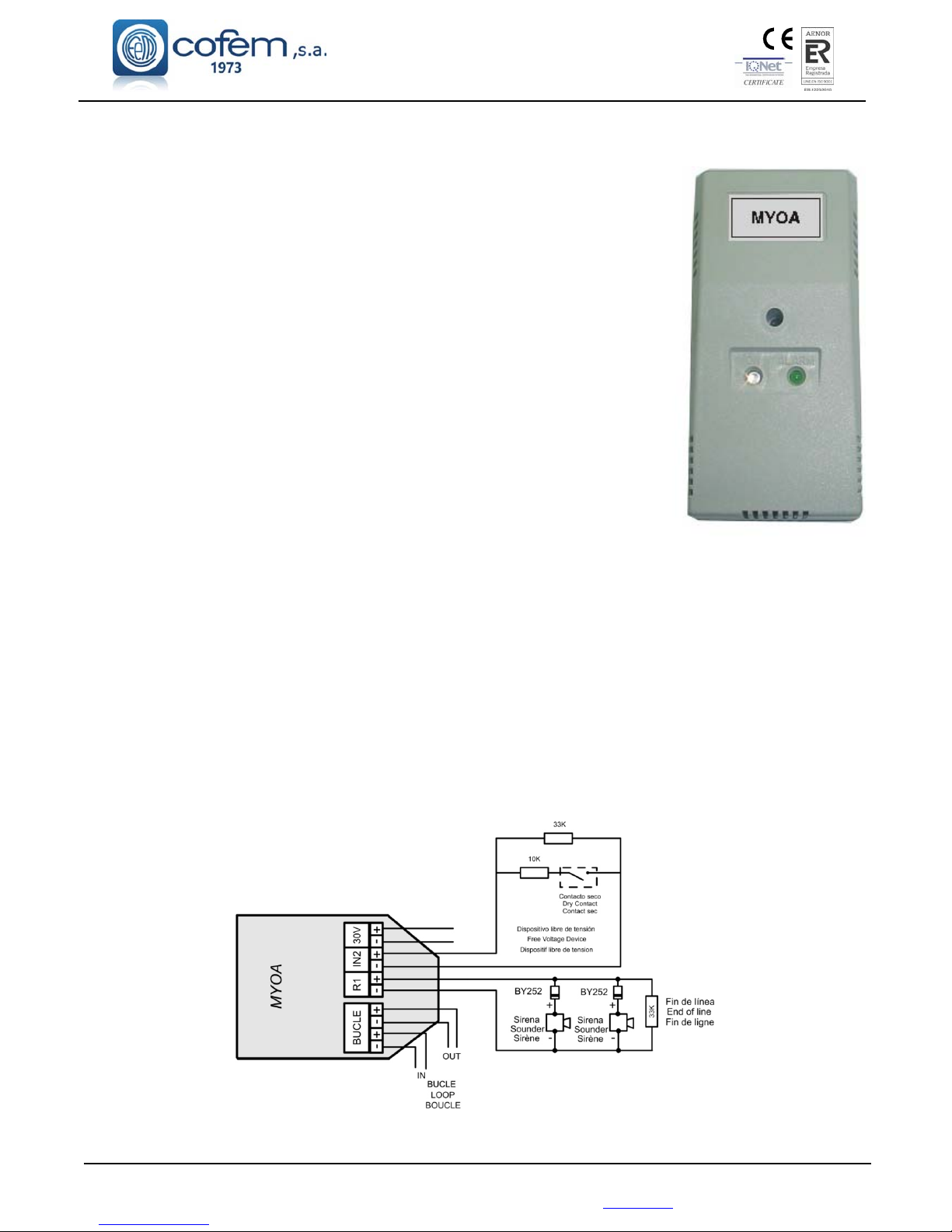
Master relay and technical signals module (MYOA)
Microprocessed analogue and addressable devices (with short-circuit
isolator) installed as another element inside the loop.
This module has one relay output fed by external 30 V and one
technical signal input to distinguish the open or closed state of a dry contact.
The Module is protected by 0.9 A resettable fuse and the relay by 0,5 A.
It is required auxiliary 30 V for feeding the equipments connected to the
relay output. The relay is configured with only one function (sounder, switched
or crossed relay), but also in its timing and in the combination of sensors that
activate it. The module monitors the presence of Voltage in the auxiliary supply
line of 30V and in the output of the monitored relay. The volatge ouput of the
realy is 30 V.
The technical signal input has a 10 K resistor connected in serie with
the dry contact. In quiescent condition, the contact has to be open, and in
anomaly condition, the contact has to be closed. In the input (marked with IN2),
the closed contact is detected as ALARM condition.
The MYOA supervises each external line (relay ouput and technical
signal input) through a 33 K each one, which allows indication of open or
closed electrical connection status.
The flashing of the transparent red LED indicates communication with the Control Panel. The
illuminated green LED indicates the actuation of the relay an alarm statu. Illumination of the green LED
indicates activation of the relay or closed dry contact. This module is electrical fed through the loop
connection.
The Realy and Technical signal Module is placed in a rectangular, heat-resistant ABS box.
The MYOA is conformant with EN 54-18 with the conformity mark awarded by AENOR.
The Realy and Technical signal Module is placed in a rectangular, heat-resistant ABS box.
Note: To determine the number of MYOA it can be installed, consult the devices limit per
control panel table (Chapter 1.5)
Figure 9. Connection schematic MYOA
INPUT
+
-
Page 26
Digital fire detection control panel
LYON
FIRE PROTECTION MANUFACTURER
Ctra. de Molins de Rei a Rubí, Km. 8,4 - 08191 RUBÍ (Barcelona) ESPAÑA.
1.5.4.- Repeaters
1.5.4.1.- Installation
The repeater must be fixed on a vertical wall face. The side slots must be left free for heat to escape.
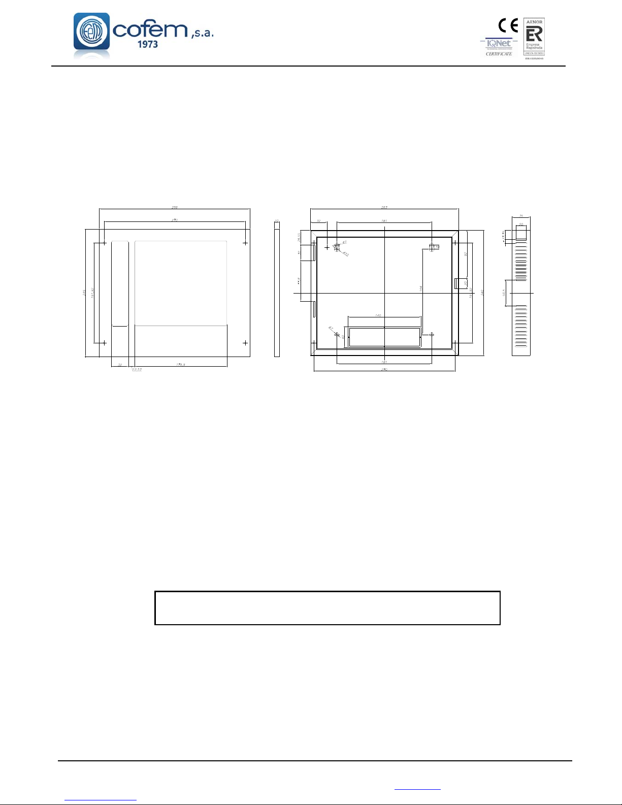
The dimensions and the pre-drilled holes for cable entry are shown in the following diagram.
Figure 10. Repeater box
The LYON control panel allows up to 15 repeaters to be connected to it. For this, a 4-wire
connection of 1.5 mm
2
wires (two for power supply and two for communication, for the RS485 line) must be
used. The two wires for the RS485 line are to be connected from the control panel’s back panel to the
terminals of each control panel labelled as “REPETITOR” in the front label. The two power supply wires are
to be connected from the 30V output of the control panel’s power supply to the terminal labelled as 30 V of
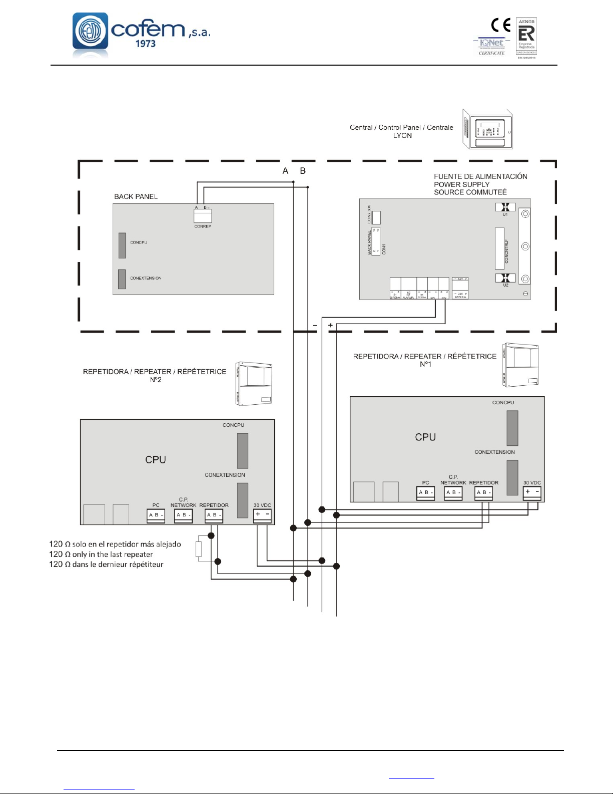
the corresponding repeaters. The repeaters must be connected as shown in figure 11.
Up to 3 repeaters can be connected to the Lyon control panel’s power supply 30V output. From
4 to 15 repeaters must be fed from the 30V output of an auxiliary power supply (FAE).
For connecting the repeaters, both the communication and 30V power supply cables must be
2 x 1.5 mm HALOGEN-FREE SCREENED BRAIDED CABLE, up to a maximum cable length of
1200 metres.
On completing the installation, a 120 Ohm resistor must be connected between the terminals A and B
in the “REPETITOR” connector of the last repeater connected.
DISCONNECT the 110~230V MAINS voltage and the BATTERIES
before handling the inside of the control panel or the repeaters.
1.5.4.2. Operation and Configuration
The repeaters display all the information about alarms, disconnections, relay actuations and faults.
Once the repeaters have been connected, they must then be configured in the control panel by
entering the number of each repeater to be configured. To do this, follow this sequence in the control panel:
Menu (access code 27) 4. System configuration (access code 9000) 8 Communications 1- Repeater
network 2 - Configure repeaters.
Page 27
Digital fire detection control panel
LYON
FIRE PROTECTION MANUFACTURER
Ctra. de Molins de Rei a Rubí, Km. 8,4 - 08191 RUBÍ (Barcelona) ESPAÑA.
Tlf.: +34 935 862 690 - Fax:+34 936 999 261 - [email protected] - www.cofem.com 27
After configuring the control panel, a number must then be assigned to each repeater. This must be
the same as the one which was configured in the control panel. To do this, follow this sequence in the
corresponding repeater: Menu (access code 27) 1. System configuration (access code 9000) 3-
Repeater number.
When configuration has been completed, the general system reset must be performed from the
control panel. To do this, follow this sequence: Menu (access code 27) 8- General reset. The zone labels
must then be sent according to this sequence in the control panel: Menu (access code 27) 1. System
configuration (access code 9000) 3 Configure 7 Send Zones to Repeaters.
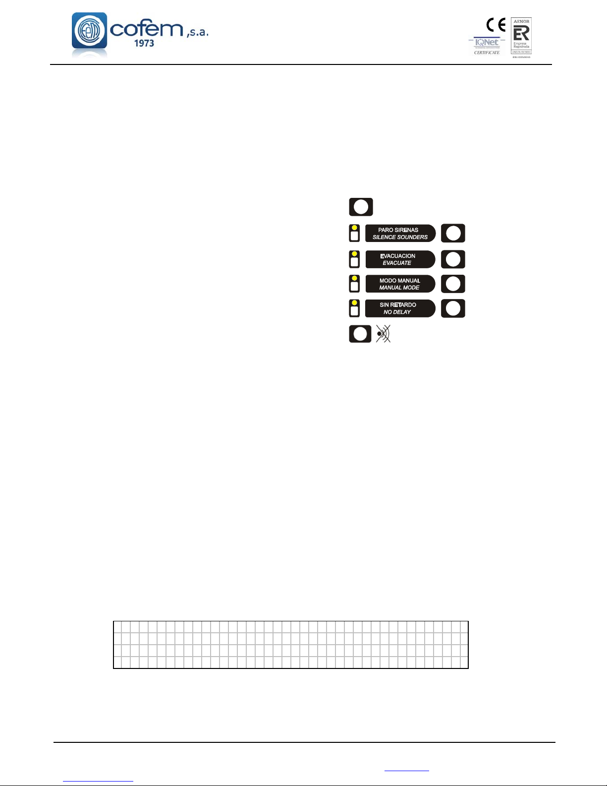
Functions that can be carried out from the repeater:
Reset alarms and faults. RESET
Activate or deactivate silence sounders.
Activate or deactivate evacuation.
Activate or deactivate manual mode.
Activate or deactivate delays.
Deactivate the buzzer.
General reset.
1.5.4.3.- Repeater menus
The following menus are accessible in the repeater:
SYSTEM CONFIGURATION
ADDITIONAL PASSWORDS: From this menu, an additional password can be entered for
access level 2 and another password for access level 3. Every time a new password is entered,
the password entered previously will be deleted. The passwords which came pre-installed from
the factory (access level 2: 27; and in access level 3: 9000) cannot be deleted.
LANGUAGES MENU: From this menu, the repeater’s language can be selected. The repeater
has Spanish, English, French, Italian, Hungarian, Ukrainian and Portuguese pre-installed at
factory.
REPEATER NUMBER: From this menu, the repeater number to be used when communicating
with the control panel can be selected. This number can never be used in more than one repeater.
GENERAL RESET: From this option, the whole system can be reset. When the system is reset, all
the events are deleted from the control panel and the repeaters, i.e. alarms, faults and relay
actuations. The status of the elements and/or zones that are out of service is maintained.
SYSTEM TEST: This option is used to test the repeater's indicators. In this test, all the leds should
light up, the buzzer should sound, and the following screen should be displayed:
█
███████████████████████████████████████
████████████████████████████████████████
████████████████████████████████████████
███████████████████████████████████████
█
WELCOME MESSAGE: From this option, the welcome message can be changed. The welcome
message is the text that is displayed in the first line when the repeater is in standby. This message
can have up to 40 characters. These are entered using the repeater’s cursors or an external keyboard.
Page 28
Digital fire detection control panel
LYON
FIRE PROTECTION MANUFACTURER
Ctra. de Molins de Rei a Rubí, Km. 8,4 - 08191 RUBÍ (Barcelona) ESPAÑA.
Figure 11. Repeater connection
Page 29
Digital fire detection control panel
LYON
FIRE PROTECTION MANUFACTURER
Ctra. de Molins de Rei a Rubí, Km. 8,4 - 08191 RUBÍ (Barcelona) ESPAÑA.
Tlf.: +34 935 862 690 - Fax:+34 936 999 261 - [email protected] - www.cofem.com 29
352
R5
R4
416
7
266
88
17
120
148
311
22
8
342
342
1.5.5.- Control panels network
1.5.5.1.- Installation
The control panel must be assembled on a vertical face. The lateral grooves in the control panel must
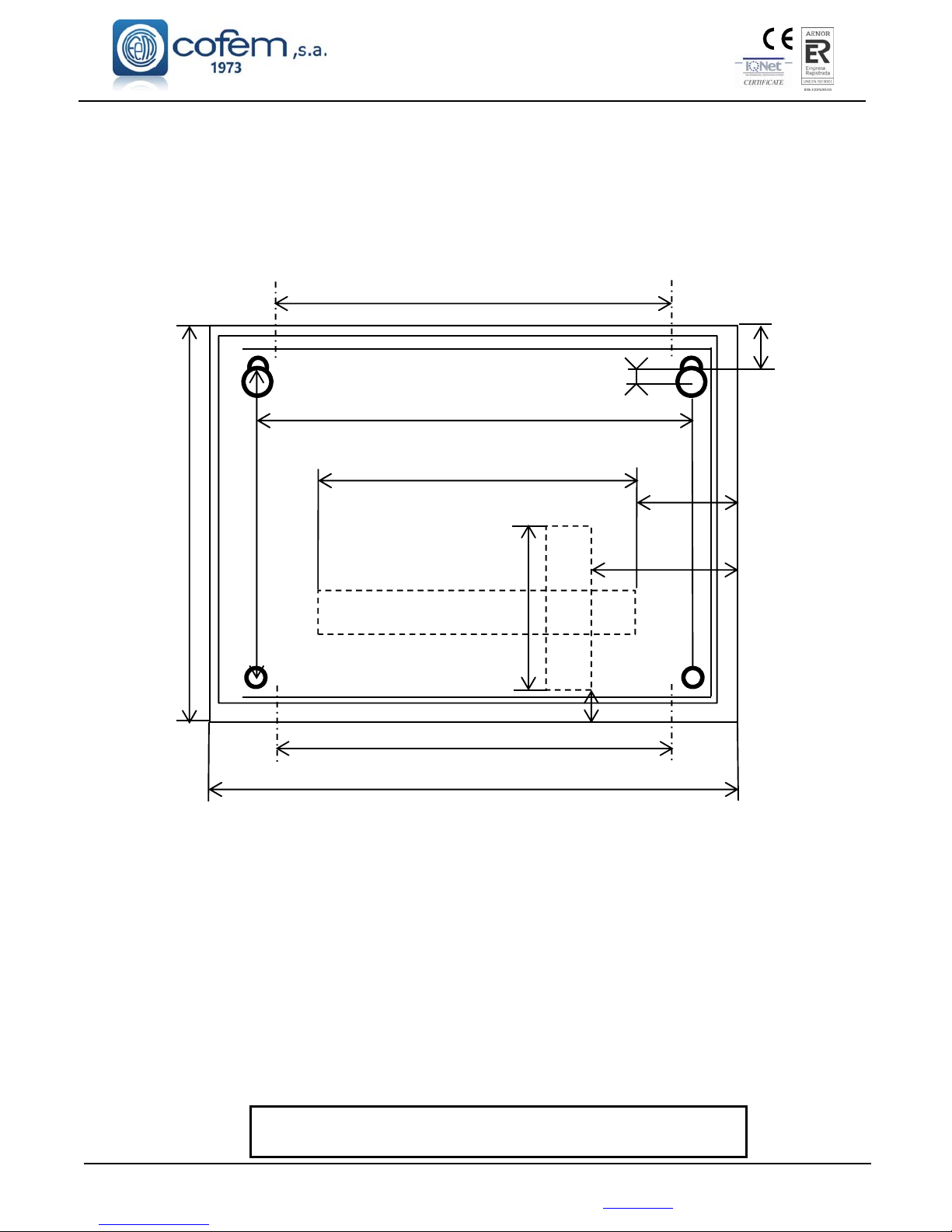
be left free for correct heat evacuation. The dimensions and pre-drilling for the cable input are in the
following figure.
Figure 12. Lyon box
Cofem Digital Detection System allows to connect up to 15 control panels in a network, by
connecting 2 wires of 1,5 mm
2
(RS485 communication line). The two wires of the RS485 line will
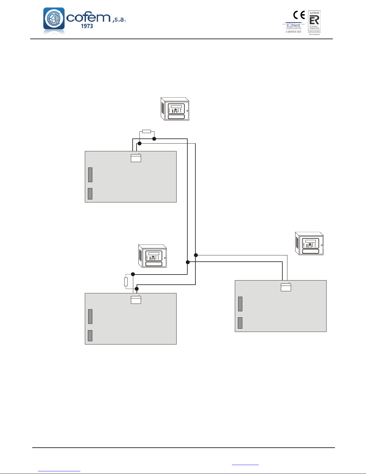
be connected from the “CONRED” indication in the back panel of each control panel. Such
connections are shown in Figure 13.
Power is held in each control panel separately. Each control panel will be connected to
the 110~230V mains and its corresponding set of batteries.
The communication cables connection between control panels will be made with cable
2 x 1,5 mm twisted shielded halogen free, up to a maximum cable length of 1200 meters.
On completing the installation, a 120 Ohm resistor must be connected between the terminals A and B
in the “CONRED” connector both the first and the last control panel connected.
DISCONNECT the 110~230V MAINS voltage and the BATTERIES
before handling the inside of the control panel or the repeaters.
Page 30

Digital fire detection control panel
LYON
FIRE PROTECTION MANUFACTURER
Ctra. de Molins de Rei a Rubí, Km. 8,4 - 08191 RUBÍ (Barcelona) ESPAÑA.
1.5.5.2.- Operation and configuration
Each control panel in the network displays all information from other control panel and
interact with each other.
Once the power connection, proceed to the configuration in each of the control panels,
entering the number of each (without repeat). For this we perform the following sequence in control
panel menu (code 27): Menu (code 27) 4- System configuration (code 9000) 8- Communications
3- Set control panel number.
After the configuration should perform a general reset at each control panel of the network.
For this we perform the following sequence: Menu (code 27) 8- General reset.
A control panel in the network can perform the same functions as any normal control panel.
You can also perform the following functions on the rest of the control panels of the network:
Reset alarms and faults in the network control panels.
Reset all the network control panels.
Enable or disable without delay mode in all network control panels.
Enable or disable sirens stop in all network control panels.
Enable or disable the evacuation in all network control panels.
Enable or disable manual mode in all network control panels.
Disable the buzzer in all network control panels.
1.5.5.3.- Control panels network menu
In the control panels we can find the next specific control panels network menus:
VISUALIZE CONTROL PANELS: Visualize the set control panels.
RESET CONTROL PANEL NETWORK: Reset all the control panels in the network.
SPECIAL FUNCTIONS:
WITHOUT DELAY: Enable or disable all the delays of all the relays associated with
all network control panels.
OFF SIRENS: Enable or disable all the sirens stop associated with all network
control panels.
EVACUATION: Enable or disable all the relays associated with all network control
panels.
MANUAL MODE: Enable or disable manual mode in all network control panels.
SETUP CONTROL PANEL NUMBER:
ENTER CONTROL PANEL NUMBER.
CONTROL PANEL NUMBER:
VISUALIZE THE CONTROL PANEL NUMBER.
Page 31
Digital fire detection control panel
LYON
FIRE PROTECTION MANUFACTURER
Ctra. de Molins de Rei a Rubí, Km. 8,4 - 08191 RUBÍ (Barcelona) ESPAÑA.
Tlf.: +34 935 862 690 - Fax:+34 936 999 261 - [email protected] - www.cofem.com 31
Figure 13. Control panels network connection
BACK PANNEL
AB
A B
CONRED
CONCPU
CONEXTENSION
Central / Control Panel / Centrale
LYON Nº1
Central / Control Panel / Centrale
LYON Nº3
Central / Control Panel / Centrale
LYON Nº2
BACK PANNEL
A
B
CONRED
CONCPU
CONEXTENSION
120
central más alejada
BACK PANNEL
A
B
CONRED
CONCPU
CONEXTENSION
120
primera central
Page 32
Digital fire detection control panel
LYON
FIRE PROTECTION MANUFACTURER
Ctra. de Molins de Rei a Rubí, Km. 8,4 - 08191 RUBÍ (Barcelona) ESPAÑA.
352
R5
R4
416
7
266
88
17
120
148
311
22
8
342
342
1.6.- Accessories.
1.6.1.- PC Keyboard
The control panel LYON system allows a standard PC keyboard to be connected, with PS2
connector (minidin6), thereby enabling the programming and the labelling of zones, elements and relays.
1.6.2.- PC based configuration software.
Software is available for the analogue control panel LYON (I-Link), that means of which the user
can perform all the control panel programming in a simple and intuitive way. With this system it will be
possible to maintain the configuration for future use.
The minimum configuration of the PC is:
1.8 GHz
Windows 7,8,10
2 GB of RAM
1 GB free space on the hard disk
DirectX9 Minimum resolution 1024x768
Free USB port
2.- Installation
2.1.- Control panel installation.
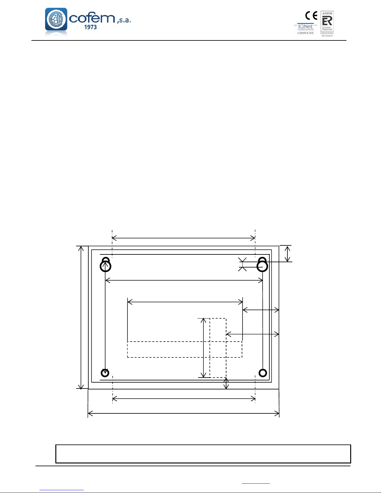
The control panel must be assembled on a vertical face. The lateral grooves in the control panel must
be left free for correct heat evacuation. The dimensions and pre-drilling for the cable input are in the
following figure.
Figure 14. Centralised Lyon system box
Any connection or movement of the control panel must be carried out with the panel disconnected, both
from the power supply, and from the batteries.
Page 33
Digital fire detection control panel
LYON
FIRE PROTECTION MANUFACTURER
Ctra. de Molins de Rei a Rubí, Km. 8,4 - 08191 RUBÍ (Barcelona) ESPAÑA.
Tlf.: +34 935 862 690 - Fax:+34 936 999 261 - [email protected] - www.cofem.com 33
2.2.- Lyon analogue system connection
Connection of the Lyon analogue system will be carried out with 2 x 1.5 mm BRAIDED CABLE
SCREENED HALOGEN FREE, both the loops as well as the sirens, KMAY connected elements and
failure outputs and 30 volt supplies.
The loop must be connected using HALOGEN-FREE SCREENED BRAIDED CABLE
2 x 1.5 mm for lengths of up to 800 metres and HALOGEN-FREE SCREENED AND BRAIDED
CABLE 2 x 2.5 mm for lengths of up to 1500 metres.
Connection of the loop elements will be carried out in accordance with the schematics indicated in
figures 2, 3, 4, 5, 6, 7, 8, 9.
As the assembly of a loop sensor is performed (A30XTA, A30XHA and A30XHTCO), the cover on
each sensor must be replaced until the installation is completely finished and clean.
A list must be made for each loop with the location, type and programming number of each element, this
programming number goes from 1 to the 65533, see the example in the following table:
Loop: 01
POINT Programming no. Label Type Notes
1 12757 ROOM 101 A30XHA
2 12432 ROOM 102 A30XHA
3 4767 BUTTON P1 PUCAY
4 6982 CORRIDOR P1 MDA1Y
DISCONNECT the 110~230V Voltage circuit and BATTERIES
before accessing the interior of the control panel.
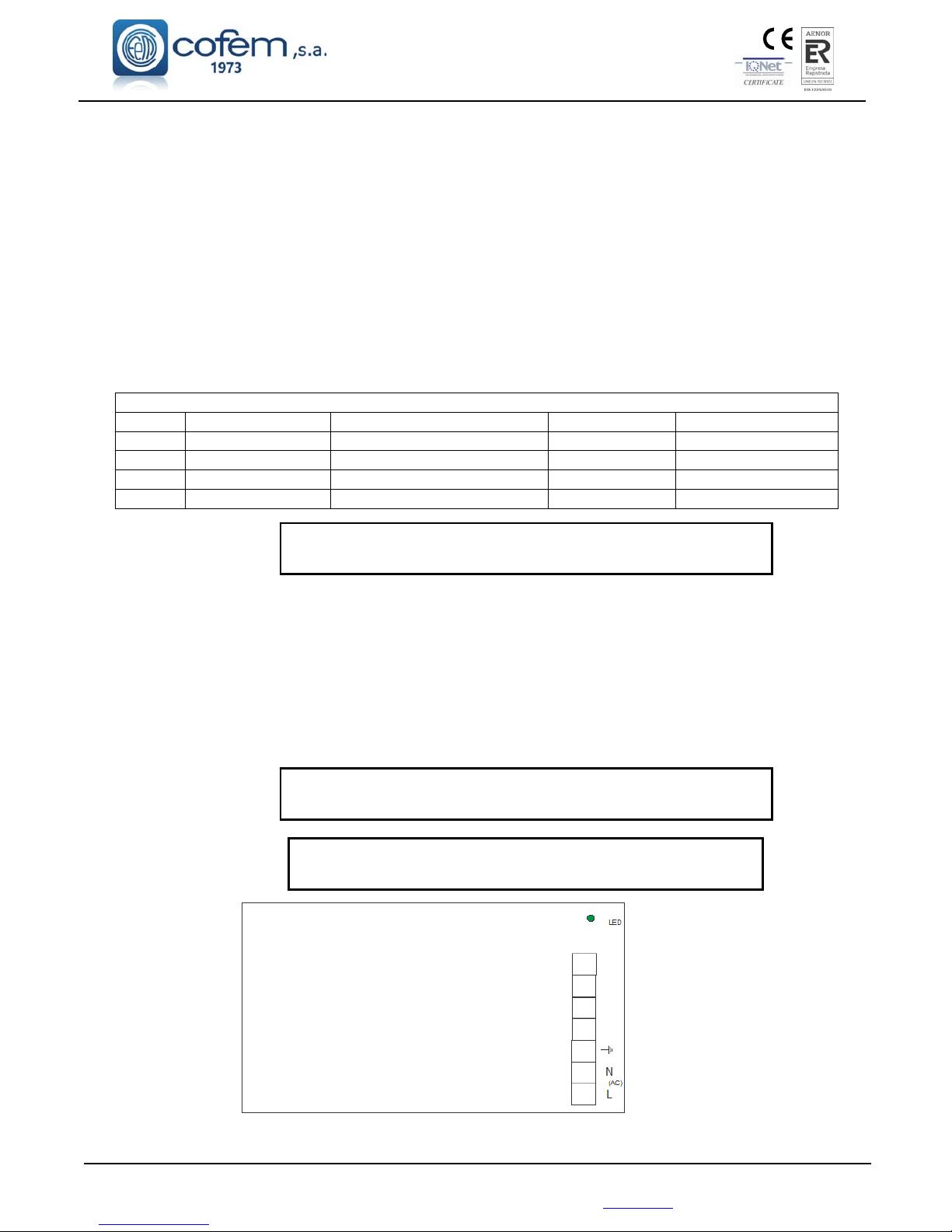
2.2.1.- Electrical supply network.
Power supply is 110~230V ±10% 50 - 60 Hertz. Connection will be made by means of 3 strands
with a minimum section of 1.5mm the connection of the earth cable to the terminal of the switched supply
being obligatory. The maximum consumption for a control panel of up to 8 loops is 150 W and for control
panel of 9 to 20 loops is 300W.
Connection will be made according to figure 15.
DISCONNECT the 110~230V Voltage circuit and BATTERIES
before accessing the interior of the control panel.
Do not cut power to the control panel during the boot process.
Such action may cause malfunction of the unit.
Switched Source
Figure 15. Switched Source
Page 34
Digital fire detection control panel
LYON
FIRE PROTECTION MANUFACTURER
Ctra. de Molins de Rei a Rubí, Km. 8,4 - 08191 RUBÍ (Barcelona) ESPAÑA.
2.2.2.- Loop driver
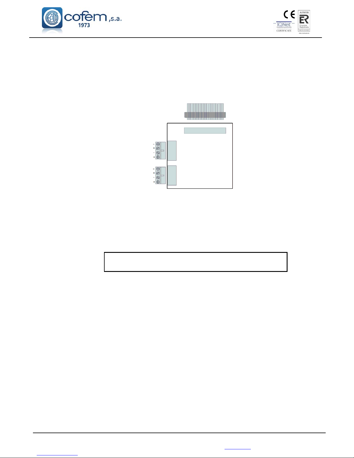
The standard control panel can have a maximum of 4 loop drivers of 2 loops, located in its interior.
In the event of needing more than 8 loops, that is to say, more than 4 drivers, the control panel will be
provided with two joined boxes providing a maximum of 20 loops.
35V Supply
Driver controller connection
LOOP 1
LOOP 2
Figure 16. Loop driver
Each loop driver is numbered, to identify the corresponding loop. The numbering and the polarity
come on the strip connector.
Connection of the loops of the Lyon analogue system will be made with 2 x 1.5 mm BRAIDED
SCREENED HALOGEN-FREE CABLE for lengths of up to 800 metres and 2 x 2.5 mm BRAIDED
SCREENED HALOGEN-FREE CABLE for lengths of up to 1500 metres.
Connection will be made according to figure 19.
DISCONNECT the 110~230V Voltage circuit and BATTERIES
before accessing the interior of the control panel.
Page 35
Digital fire detection control panel
LYON
FIRE PROTECTION MANUFACTURER
Ctra. de Molins de Rei a Rubí, Km. 8,4 - 08191 RUBÍ (Barcelona) ESPAÑA.
Tlf.: +34 935 862 690 - Fax:+34 936 999 261 - [email protected] - www.cofem.com 35
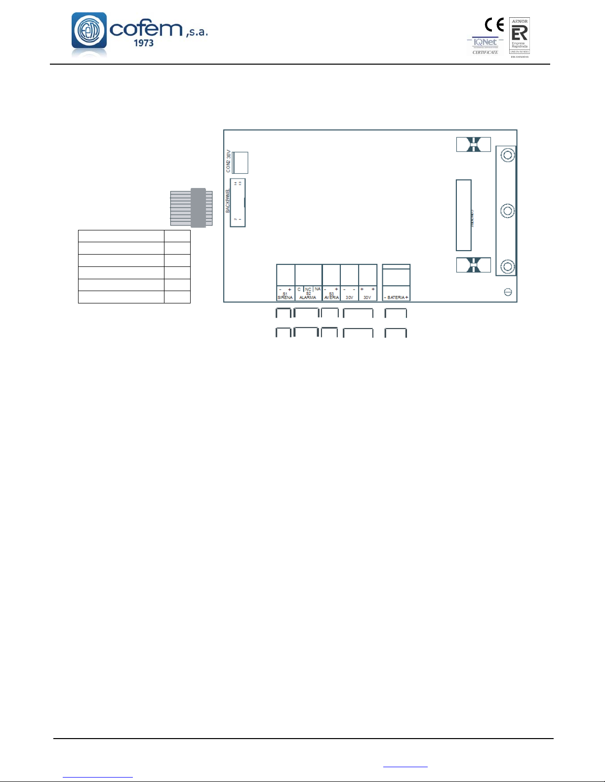
2.2.3.- Power supply auxiliary outputs and charging of power source batteries.
Power supply board:
30v DC output
supply for battery
charger control
CPU and sirens
Power supply
Supply fuse 8 A
Battery fuse 5 A
Bat. charger fuse 1 A
30V fuse 2 A
S1 Siren fuse 2 A
S3 Fault fuse 1 A
COMMON
+24
V
COMMON
NC
NA
COMMON
+24
V
GND
GND
+30
V
+30
V
GND
+24v
MONITORED
SIREN
ALARM
OUTPUT
FAULT
OUTPUT
AUXILIARY
30V OUTPUT
24V
BATTERIES
Figure 17. Power supply auxiliary outputs
S1 Sounder
Output of the monitored siren and protected by means of a fuse, to which a delay can be
applied by means of the configuration menu, see 3 chapter configuration.
The installation of sirens will be performed according to the schematic of figure 19. It will be
activated whenever an alarm occurs in the system and the programmed delay has passed. It is
only deactivated when there is no alarm in the system.
S2 Sounder
Unmonitored voltage-free output exit. It is activated whenever an alarm occurs in the system.
It is only deactivated when there is no alarm in the system.
S3 Fault
Monitored fault output and protected by means of fuse, to which a delay can be applied by
means of the configuration menu, see 3 chapter configuration. It will be activated whenever there
is a fault in the system and the programmed delay has passed. It is only deactivated when there is
no fault in the system.
Auxiliary 30V output
This is a 30V output that enables the supply of analogue modules or relays or other external
devices. This output is monitored and protected by means of a fuse.
Page 36
Digital fire detection control panel
LYON
FIRE PROTECTION MANUFACTURER
Ctra. de Molins de Rei a Rubí, Km. 8,4 - 08191 RUBÍ (Barcelona) ESPAÑA.
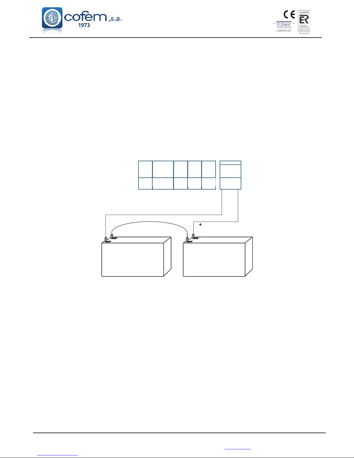
2.3.- Components.
2.3.1.- Batteries.
The supervised battery input/output allows the connection of batteries to the control panel. The
batteries are charged through this connection as well as the monitoring of its status. The battery charge is
compensated depending on the temperature of the batteries. This input/output is protected by a fuse and also
against inversion of polarity. In addition to this fuse there is the battery charger fuse.
The capacity of the batteries that are incorporated into the control panel will depend on the number
of loops and additional loads (e.g. relays modules), 7Ah being the minimum recommended. Batteries with a
capacity of 15Ah or 24Ah will have to be housed in a box external to the control panel, ref C-55.
Connection of the two 12V batteries in series is exactly as indicated in figure 18.
Power supply
Figure 18. Battery connection schematic
2.3.2.- Connection schematic of a typical loop.
Connection of the Lyon analogue system will be made with CABLE OF 2 x 1.5 mm TWISTED
AND SCREENED HALOGEN FREE not only loops but also sounder and fault outputs and elements
connected to the KMAY and the 30V supplies.
The loop is to be connected using 2 x 1.5 mm TWISTED AND SCREENED HALOGEN FREE
for lengths of up to 800 metres and 2 x 2.5 mm TWISTED AND SCREENED HALOGEN FREE for
lengths of up to 1500 metres.
NOTE: For specific details of how each element is to be connected, please see the relevant chapter.
12V
12V
-
-
+
-
+
BATERIA
-
+
++
30V
30V
-
-
AVE RIA
S3
-
+
S2
ALARMA
NC
C
NA
S1
SIRENA
+
-
Page 37
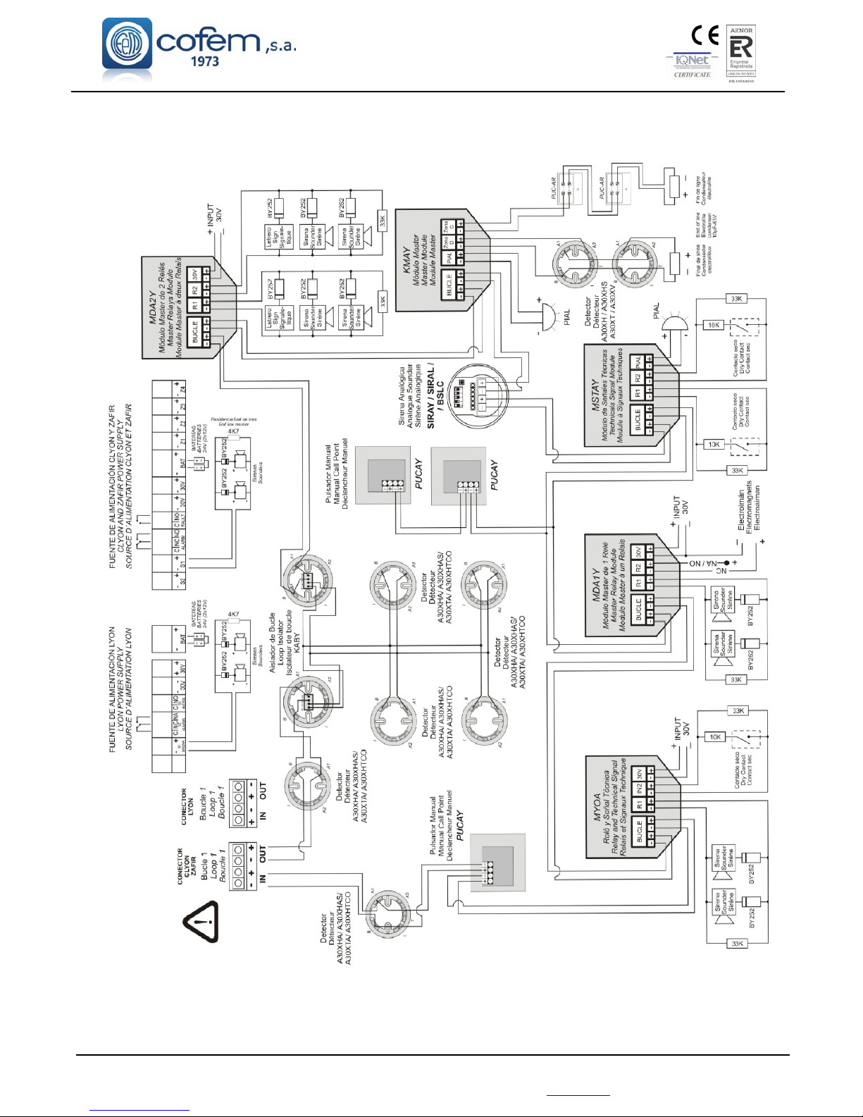
Digital fire detection control panel
LYON
FIRE PROTECTION MANUFACTURER
Ctra. de Molins de Rei a Rubí, Km. 8,4 - 08191 RUBÍ (Barcelona) ESPAÑA.
Tlf.: +34 935 862 690 - Fax:+34 936 999 261 - [email protected] - www.cofem.com 37
Figure 19. General Wiring Diagram
Page 38
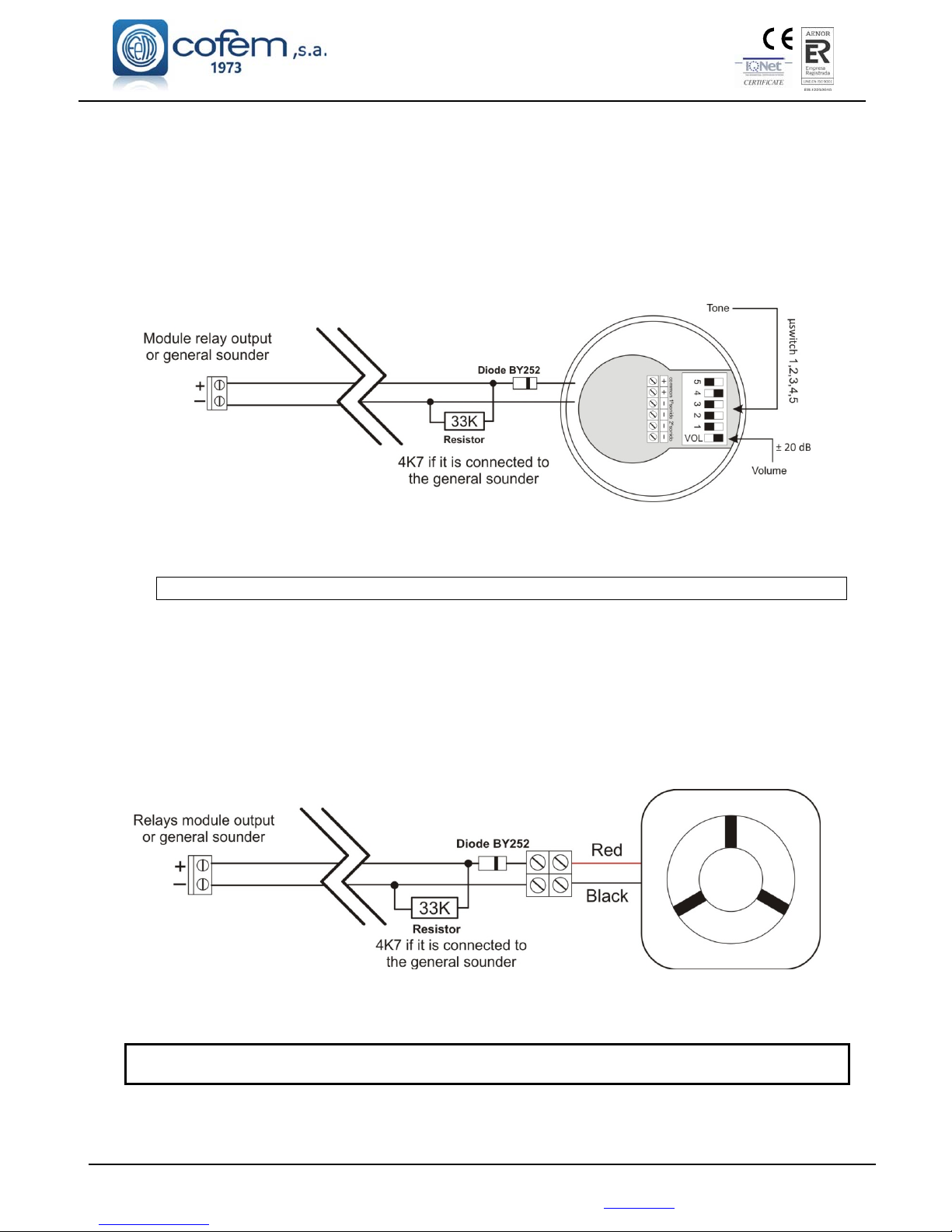
Digital fire detection control panel
LYON
FIRE PROTECTION MANUFACTURER
Ctra. de Molins de Rei a Rubí, Km. 8,4 - 08191 RUBÍ (Barcelona) ESPAÑA.
2.3.3.- Sounder and controls with relays.
2.3.3.1.- Connection of the internal two tone 24V Sounder (SIR-24B/SIR-24BL)
Elements needed for its correct installation:
1 Resistance 33 KΩ, in the event of being connected to the general sounder the resistance is 4K7,
included in the control panel and/or modules.
1 Diode BY252, two diodes are included with each control panel Lyon system.
Figure 20. SIR-24B/SIR-24BL connection schematic
NOTE!! An auxiliary 30V supply is necessary for MYOA, MDA1Y and MDA2Y modules
2.3.3.2.- Connection of the non-flashing internal 24V Sounder (SIR24P)
Elements needed for its correct installation:
1 Resistance of 33 KΩ; in the event of the sounder being connected to the general sounder, the
resistance should be 4K7, which is included in the control panel and/or the modules.
1 BY252 Diode; two diodes are included with each Lyon control panel.
Figure 21. SIR24P Connection schematic
Modules MYOA, MDA1Y and MDA2Y require an auxiliary 30V power supply
Page 39
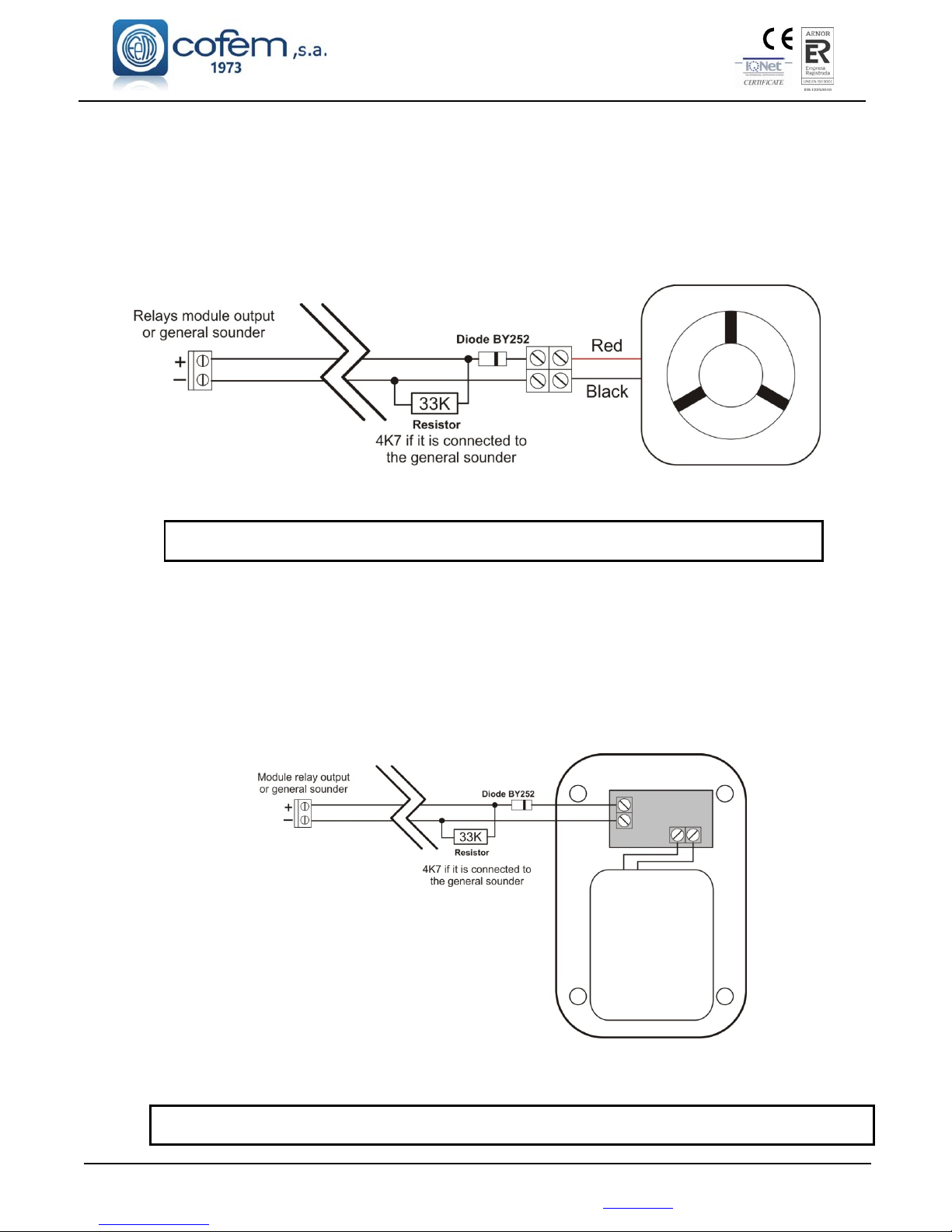
Digital fire detection control panel
LYON
FIRE PROTECTION MANUFACTURER
Ctra. de Molins de Rei a Rubí, Km. 8,4 - 08191 RUBÍ (Barcelona) ESPAÑA.
Tlf.: +34 935 862 690 - Fax:+34 936 999 261 - [email protected] - www.cofem.com 39
Auxiliary 30V supply is required for the MYOA, MDA1Y and MDA2Y modules
2.3.3.3.- Connection of the flashing internal 24V Sounder (SIR24F)
Elements needed for its correct installation:
1 Resistance of 33 KΩ; in the event of the sounder being connected to the general sounder, the
resistance should be 4K7, which is included in the control panel and/or the modules.
1 BY252 Diode; two diodes are included with each Lyon control panel.
Figure 22. CAE24V Connection schematic
2.3.3.4.- Connecting the external 24V alarm box (CAE-PL)
Elements needed for its correct installation:
1 33 KΩ Resistance; in the event of the sounder being connected to the general sounder, the
resistance should be 4K7, which is included in the control panel and/or the modules.
1 BY252 Diode; two diodes are included with each Lyon control panel.
Figure 23. CAE24V Connection schematic
Modules MYOA, MDA1Y and MDA2Y require an auxiliary 30V power supply
Page 40
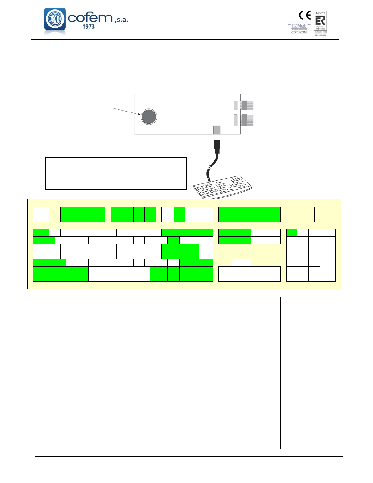
Digital fire detection control panel
LYON
FIRE PROTECTION MANUFACTURER
Ctra. de Molins de Rei a Rubí, Km. 8,4 - 08191 RUBÍ (Barcelona) ESPAÑA.
2.4.- Accessories.
2.4.1.- PC keyboard
The standard keyboard, with PS2 connection, will be connected to the plate located in the door of the
control panel as in the attached drawing.
Buzzer Display connection
Connection with the
Back panel
PS2
Minidin6
DISCONNECT the control panel and repeaters
from the MAINS 110~230V and the BATTERIES
before connecting the external keyboard.
ES
C
F9
F11 F1
2
1 2 3 4 5 6 7 8 9 0 Pg Up / * -
Q W E R T Y U I O P - Enter Pg Down 7 8 9
+
Caps
Lock
A S D F G H J K L 4 5 6
Z X C V B N M , . / Up 1 2 3
Ent
er
(SPACE)
Lef
t
Dwn Rght 0 .
F9 – Silence buzzer
F11 – Menu
F12 – Reset
Pag+ – Go forwards three options in any menu and one loop
in the monitoring screen
Pag- – Go backwards three options in any menu and one
loop in the monitoring screen
+ Numeric keypad – Advance one relay in the logical relay
configuration menu and one loop in the loop configuration
menu
- Numeric keypad – Go back one relay in the logical relay
configuration menu and one loop in the loop configuration
menu
Page 41
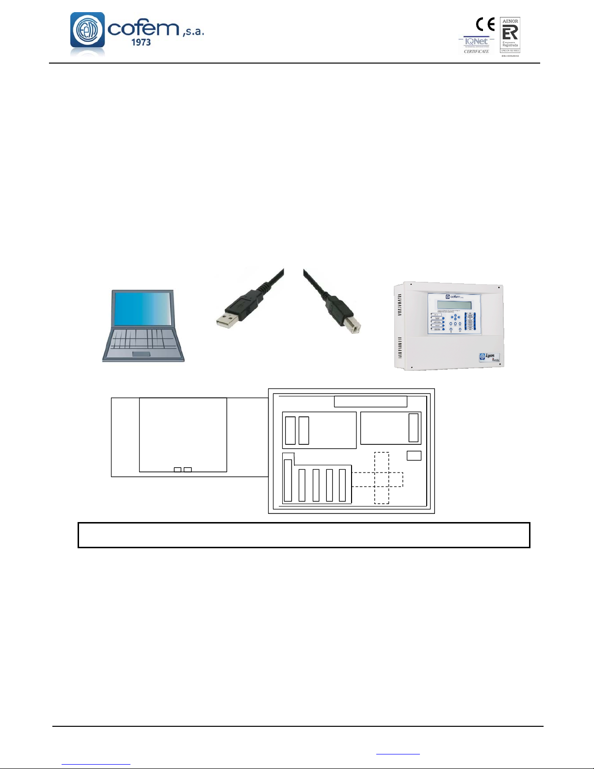
Digital fire detection control panel
LYON
FIRE PROTECTION MANUFACTURER
Ctra. de Molins de Rei a Rubí, Km. 8,4 - 08191 RUBÍ (Barcelona) ESPAÑA.
Tlf.: +34 935 862 690 - Fax:+34 936 999 261 - [email protected] - www.cofem.com
41
The connection to the USB port must be made using a cable no more than 3 metres long.
2.4.2.- Computer.
The LYON analogue control panel system can use software (I-Link), with which the user can
completely programme the control panel, easily and intuitively. By using this system, the configuration can
be saved for future use.
Minimum PC Configuration:
1.8 GHz
Windows 7,8,10
2 GB of RAM
1 GB free space on the hard disk
DirectX9 Minimum resolution 1024x768
Free USB port
As shown in the diagram the connection between the PC and the control panel must be made using a USB
2.0 PORT.
.
The use of the I-Link program and the configuration of the communication ports of the computer are
described in the manual (Manual I-Link).
In the case of installing the functionality of I-Link ONLINE, uses RS485 connection as indicated in
the control panel backpanel port with “CONPC” (instead of using the USB connection). This will avoids
potential interference with communication and allows greater separation distances between control panel and
PC. The following figure shows examples of wiring.
CPU
USB
PS2
USB
Type A Type B
Page 42
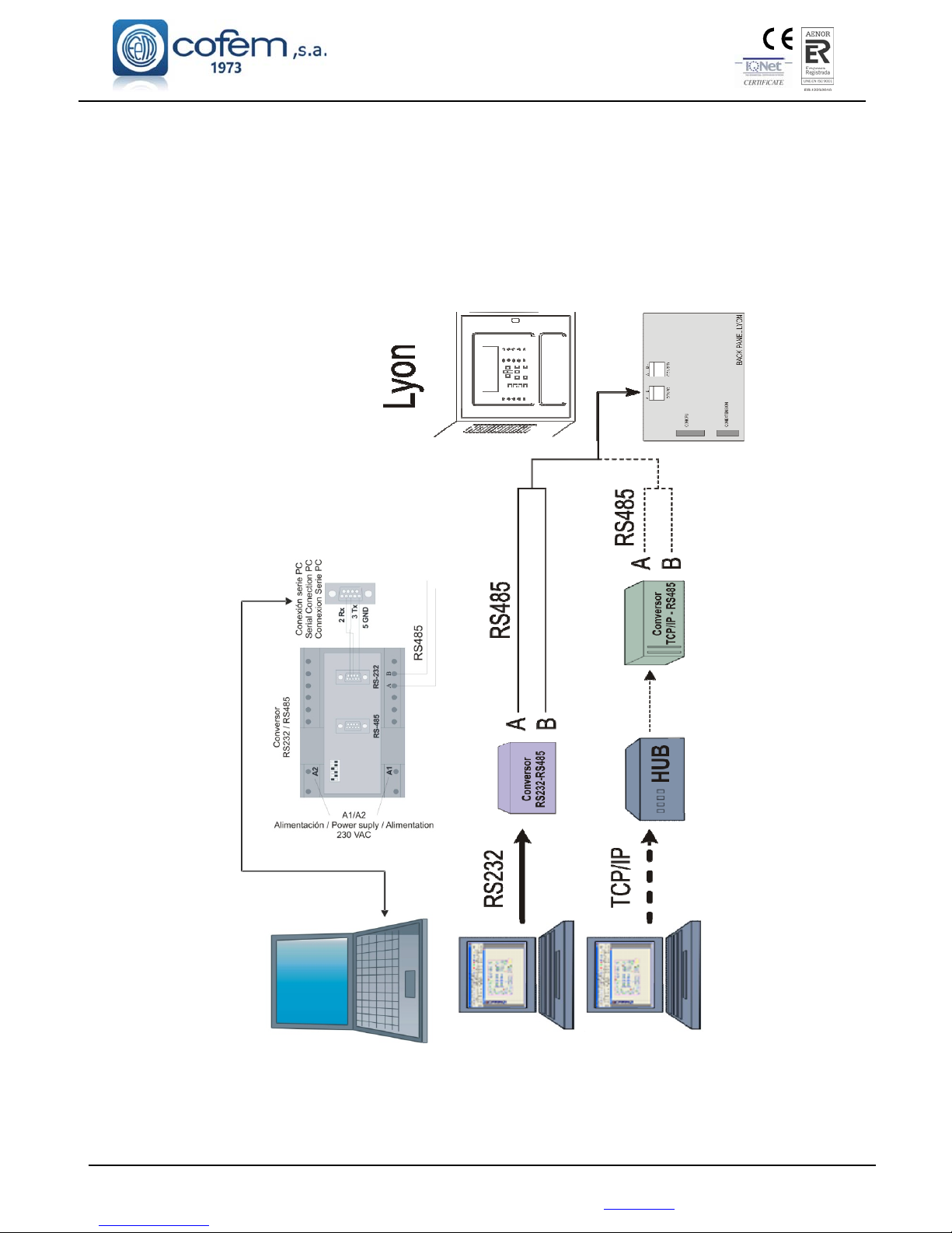
Digital fire detection control panel
LYON
FIRE PROTECTION MANUFACTURER
Ctra. de Molins de Rei a Rubí, Km. 8,4 - 08191 RUBÍ (Barcelona) ESPAÑA.
42
Example of PC connection (I-Link ONLINE) with LYON control panel
(through a RS232/RS485 converter or using TCP/IP connection)
Page 43
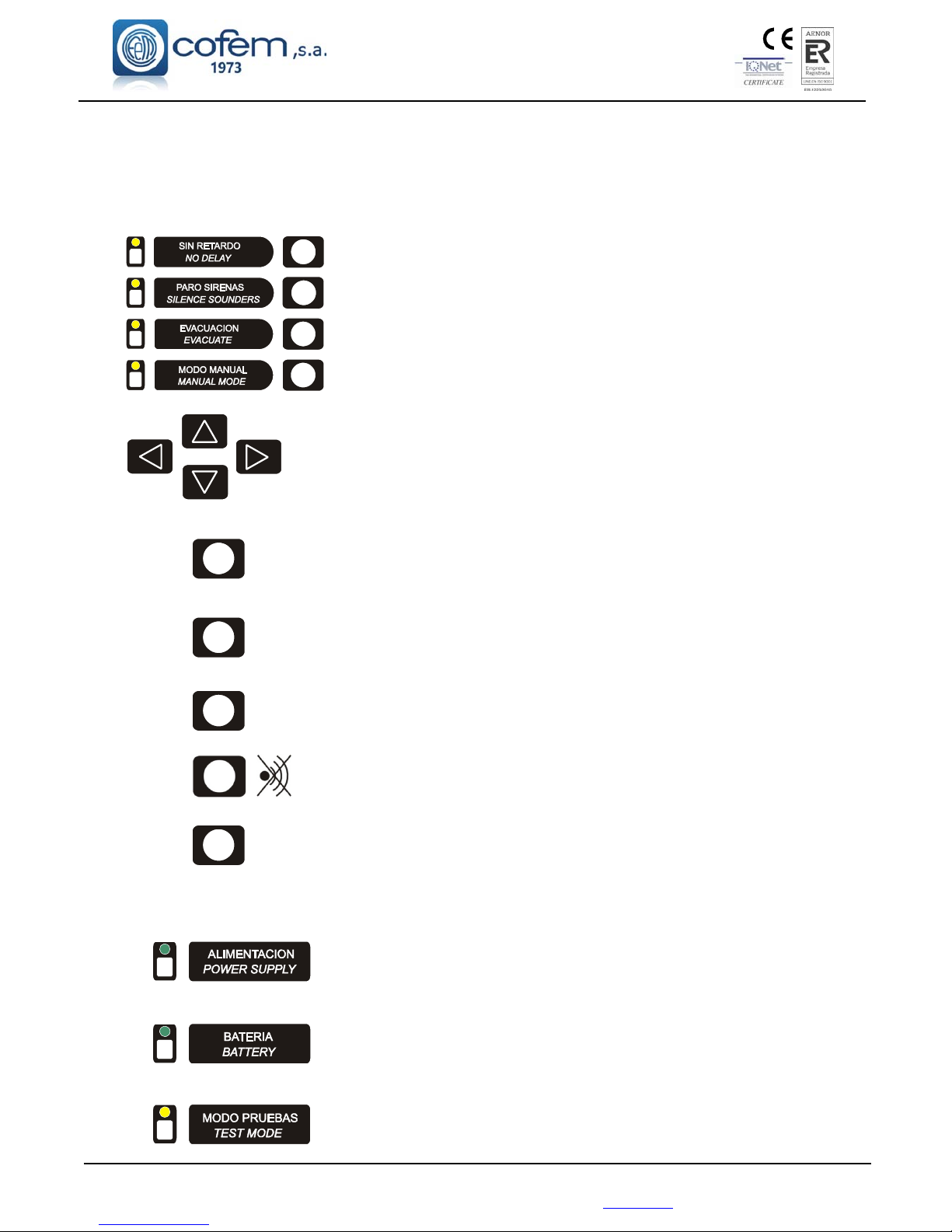
Digital fire detection control panel
LYON
FIRE PROTECTION MANUFACTURER
Ctra. de Molins de Rei a Rubí, Km. 8,4 - 08191 RUBÍ (Barcelona) ESPAÑA.
Tlf.: +34 935 862 690 - Fax:+34 936 999 261 - [email protected] - www.cofem.com 43
3.- Operation and configuration.
3.1.- Description of the front panel.
3.1.1.- Keypad.
Disable the configured relay delays
Disable all relays that are configured as sirens.
Activate all relays programmed as sirens and switches.
Change to manual mode and disable all automatic relay activations.
These cursors allow us to move through the menu that appears on the
screen and to select characters in text mode.
ESC Key that enables the user to pass from one level to a higher level in the menu
tree of the control panel and to cancel menu selections
MENU This key enables us to enter the control panel menu and to show the help
text of the various menus.
ENTER This key enables us to confirm a selection.
SILENCE BUZZER
RESET Key that enables the user to reset events that have occurred in the system.
3.1.2.- Light indicators.
Green LED indicating that the system is working by means of the
110~230V network.
Green LED indicating that the system is working from the batteries.
The POWER SUPPLY LED is off.
Amber LED indicating that the control panel is working in test mode or
some zone is working mode.
Page 44
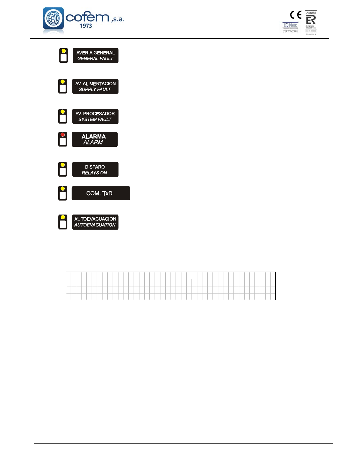
Digital fire detection control panel
LYON
FIRE PROTECTION MANUFACTURER
Ctra. de Molins de Rei a Rubí, Km. 8,4 - 08191 RUBÍ (Barcelona) ESPAÑA.
Amber LED indicating a fault. The display details the type of supply
fault.
Amber LED indicating a supply fault. The display details the type of
supply fault.
Amber LED indicating the system has ceased to function correctly.
Red LED indicating an alarm.
Amber LED indicating the control panel has activated a relay
Amber LED indicating that the control panel is communicating with an
external item of equipment such as a PC.
Amber Led indicating that auto-evacuation is active.
3.1.3.- Screen.
Backlit alphanumeric screen of 4 lines of 40 characters each.
C
DAn LYON Cofem s.a.
---------------------------------------MODE MODE 1 2 ⁄ 08 ⁄ 06
NIGHT AUTOMATIC 10:29
3.2.- Access levels.
The control panel has four levels of access:
Level 1: allows the control panel to be manipulated in its most basic functions, such as silencing
the buzzer or review of the incidences that the control panel has been able to detect.
Level 2: it is only accessible by maintenance personnel, by means of the access code (27). This
level enables functions to be performed by the authorized person that affect the self-test of the
control panel, by means of the test, such as activation of the various elements that make up the
installation (sirens, switches, crossed relays and evacuation).
Level 3: Is intended exclusively for use by competent personnel by means of the access code
(9000), since by accessing at this level we can manipulate the system configuration.
Level 4: It enables access to the interior of thecontrol panel, which is accessed by means of a
key.
Page 45
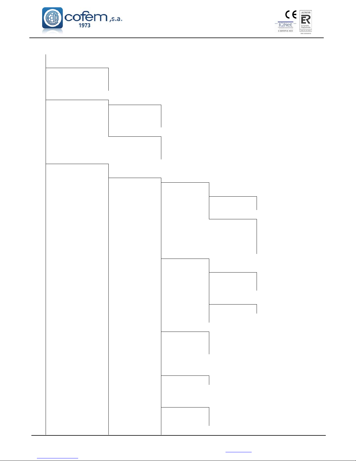
Digital fire detection control panel
LYON
FIRE PROTECTION MANUFACTURER
Ctra. de Molins de Rei a Rubí, Km. 8,4 - 08191 RUBÍ (Barcelona) ESPAÑA.
Tlf.: +34 935 862 690 - Fax:+34 936 999 261 - [email protected] - www.cofem.com 45
Control panel menu:
Menu 1
1. Monitor
2. Logical relay activation Menu 2
1. List tripped relays
2. Activate a single relay
3. Deactivate a single relay
4. Activate all sirens
5. Activate all switches
3. General relays Menu 3
1. General siren relay Menu 7
1. Activate relay
2. Deactivate relay
3. Change delay
4. Disable relay
5. Enable relay
2. Fault relay Menu 8
1. Activate relay
2. Deactivate relay
3. Change delay
4. Disable relay
5. Enable relay
4. System configuration Menu 4
1. Label e elements
2. Configure Menu 9
1. Loop configuration Menu 17
1. Sensitivity of a type
2. Flashing Menu 31
1. Flashing permitted
2. Flashing inhibited
3. View configuration
3. POINT configuration Menu 32
1. View loop information
2. Search for loop elements
3. Assign number to
element
4. Loop auto configuration
5. Delete point
6. Replace point
7. Delete loop points
2. Configure logical relays Menu 18
1. Relay actuation
2. Delay
3. Day / night Menu 33
1. Prog. day button
2. Prog. day sensor
3. Prog. night button
4. Prog. night sensor
4. Physical situation
5. Label
6. Activation mode Menu 34
1. General activation
2. Activation by list
7. View configuration
8. View list of actuations
3. Configure alarm zones Menu 19
1. Configure zone
2. Modify lists
3. Delete zone
4. Label
5. View configuration
4. Configure element
sensitivity
5. Additional passwords Menu 20
1. Password level 2
2. Password level 3
6. Conf. Auto evacuation Menu 21
1. Enable Autoev.
2. Disable Autoev.
3. Configure delay
4. Auto evacuation summary
7. Added Delay setup
Page 46
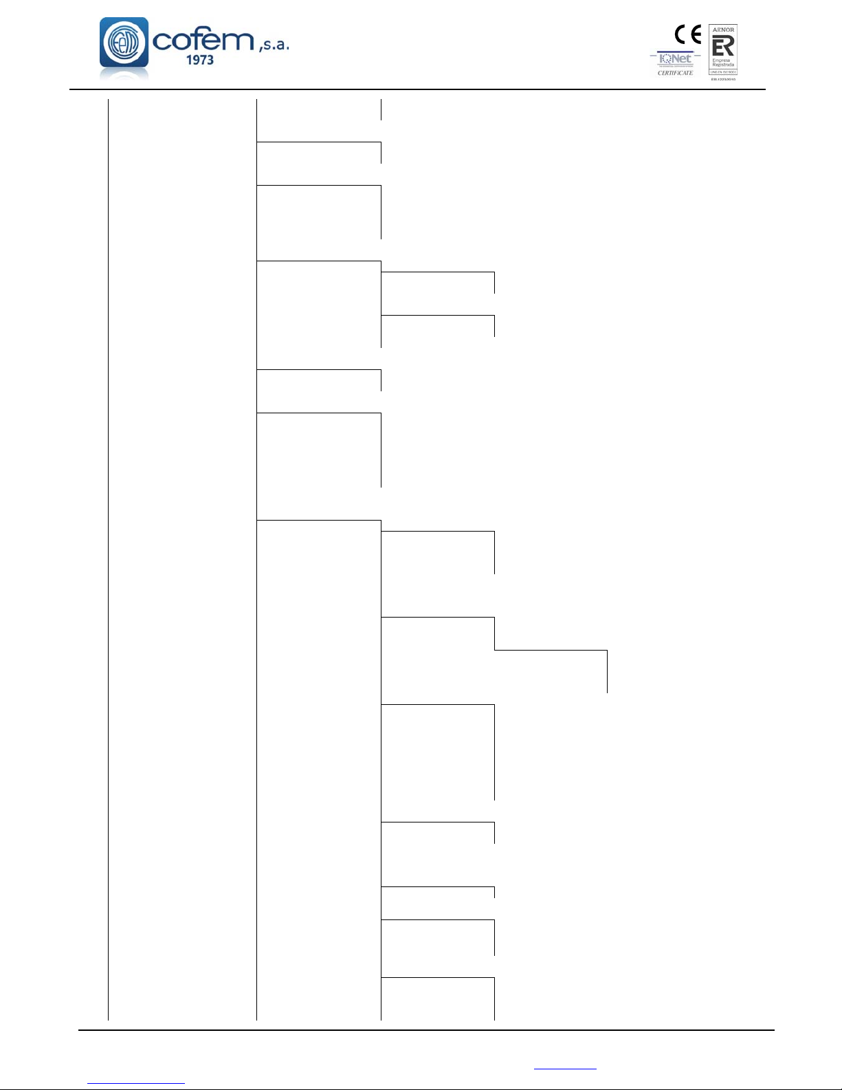
Digital fire detection control panel
LYON
FIRE PROTECTION MANUFACTURER
Ctra. de Molins de Rei a Rubí, Km. 8,4 - 08191 RUBÍ (Barcelona) ESPAÑA.
8. Fast Trigger Zone
9.Send zones to repeaters
3. Update date and time Menu 10
1. Change date
2. Change time
4. Day / night times Menu 11
1. Day time start
2. Day time end
3. Progr. night mode days
4. Delete night mode progr.
5. Programming summary
5. Put into test/ normal mode Menu 12
1. Test mode Menu 22
1. General
2. By zones
2. Normal mode Menu 23
1. General
2.By zones
3. List zones
6. Led ON/OFF Menu 13
1. Led ON
2. Led OFF
7. Language menu Menu 14
1. Language Spanish
2. Language English
3. Language French
4.Language Italian
5.Language Hungarian
6.Language Ukrainian
7.Language Portuguese
8. Communications Menu 15
1. Network of repeaters Menu 24
1. Configure repeaters
2. Auto detect slaves
3. Delete repeater
4. Label repeater
5. Delete repeaters
6. Label repeater
2. Internal network Menu 25
1. View control panels
2. Program co ntrol panels
3. Especial functions Menu 35
1.Disable delays
2.Disable sirens
3.Evacuate
4.Manual mode
3. ContactID Menu 26
1. Activate
2. Deactivate
3. Test interval
4. Phone 1 number programmin
5. Phone 2 number programmin
6. Phone 3 number programmin
7. Phone 4 number programmin
8. Phone 5 number programmin
9. Situation message programm
4. Modbus Menu 27
1. Activate
2. Deactivate
5. Conf. control panel number
6. View control panel number
7. P.C communication Type Menu 28
COM1 / COM2 / COM3
8. Intern. Net. Menu 29
1. Autodetect controllers
2. Erase loop controller
3. Erase supply controller
4. Consult version
9. Remote connection Menu 30
1. IP
2. Port
3. Mask
4. Gateway
Page 47
Digital fire detection control panel
LYON
FIRE PROTECTION MANUFACTURER
Ctra. de Molins de Rei a Rubí, Km. 8,4 - 08191 RUBÍ (Barcelona) ESPAÑA.
Tlf.: +34 935 862 690 - Fax:+34 936 999 261 - [email protected] - www.cofem.com 47
5. UMIP
6. Serial number
4. Conf. control panel number
5. View control panel number
6. P.C communication Type
9. Stop Sounders Function Menu 16
1. Activation
2. Performance
5. Put element s/ zones into/ out of
service Menu 5
1. Put pointinto service
2. Set point out of service
3. Put zone into service
4. Set zone out of service
5. List out of service zones
6. System test
7. Welcome message
8. General Reset
9. Review history Menu 6
1. Review complete history
2. Review alarms
3. Review faults
4. Review disabled items
5. Review relays
3.2.1.- Level 1 access.
3.2.1.1.- Activation of the control panel.
If the control panel is starting up correctly we see:
C
DA L y o n V 2 V x . x
(C) Co f em, S.A.
Iniciando arranque......................
V.X.X corresponds the version number of the control panel’s software.
The control panel is looking at the previous configuration data:
R
ecove r i ng p r ev i ous con f i gu r a t i on
Zones : [ ]
Re l a y s : [ ]
Upda t i ng s y s t em [ ]
The control panel is performing an automatic element search:
W
aiting automatic search......
----------------------------------------
MOD E 1 2 ⁄ 08 ⁄ 06
SEARCH I NG 10 : 29
When the control panel reaches at this screen and it remains, this confirms to us that the control
panel has been initialized correctly and that no alarms or faults of any type exist in the system.
Only the green LED is illuminated (Power). It is also possible that other screens appear
indicating anomalies of some type that are described in the following cases.
C
DAn LYON Cofem s.a.
----------------------------------------
MODE MODE 1 2 ⁄ 08 ⁄ 06
NIGHT AUTOMATIC 10: 29
Page 48
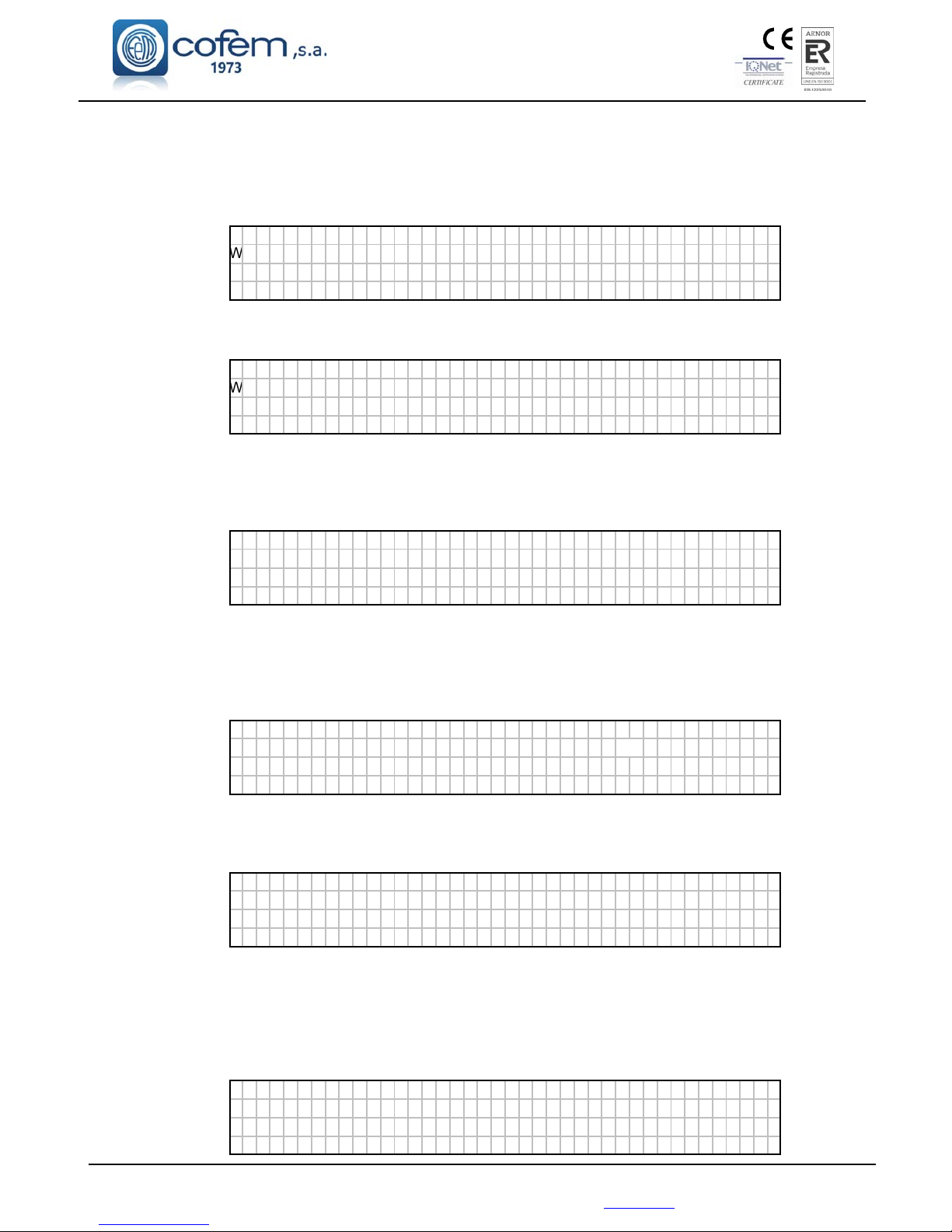
Digital fire detection control panel
LYON
FIRE PROTECTION MANUFACTURER
Ctra. de Molins de Rei a Rubí, Km. 8,4 - 08191 RUBÍ (Barcelona) ESPAÑA.
Anomalies during start-up:
1. In the event that during the start up the control panel finds a new loop or power controller,
the following message will appear. The address indicates the type of controller loop
controllers being from 1 to 5 and power controller 11.
F
ound new con t r o l l e r boa r d
W
ith address: 0XX
Press ENTER to conf i gure
P
r
ess ESC t o cont i nue
2. In the event that the control panel does not find a previously configured controller the
following message appears offering the possibility of deleting it from the configuration.
D
o no t f ound t he con t r o l l e r boa r d
W
ith address: 0XX
Press ENTER to delete
P
r
ess ESC t o cont i nue
3. In the event that the control panel does not find any loop controller, that is to say, that none
have been configured, it does not detect a new one or no controller has been configured as 1,
the following will appear:
Do no t ex i s t l oop con t r o l l er
Press ENTER to cont i nue
4. In the event of continuing from the previous message and of continuing without a loop
controller, we will have the two options that are seen in the following figure: to reinitiate the
control panel or to continue and to start up the control panel without a configured loop
controller:
COMUN I CA T I ON ERROR
LOOP CON T RO L L ER : 0 XX
Press ENTER to cont i nue
P
r
ess ESC t orun
5. In the event that the power controller does not exist, that is to say, that is to say, that none
have been configured and it does not detect a new one, the following will appear:
Do no t ex i s t powe r supp l y con t r o l l e r
Press ENTER to cont i nue
6. Finally the possibility exists that the I2C memory fails, where all the control panel
information is kept. In this case, we have two options. The first is to reinitialise the control
panel configuration, restoring the factory default values (except element and relay labels).
The second is to cancel the re-initialisation of the configuration. If after having reinitialised
the control panel the “I2C Failure” message appears again, it means that this unit is not
working correctly.
F
aul t In I2C memory
Reboo t t he con f i gu ra t i on
Press ENTER to cont i nue
P
r
ess ESC t o cance l
Page 49
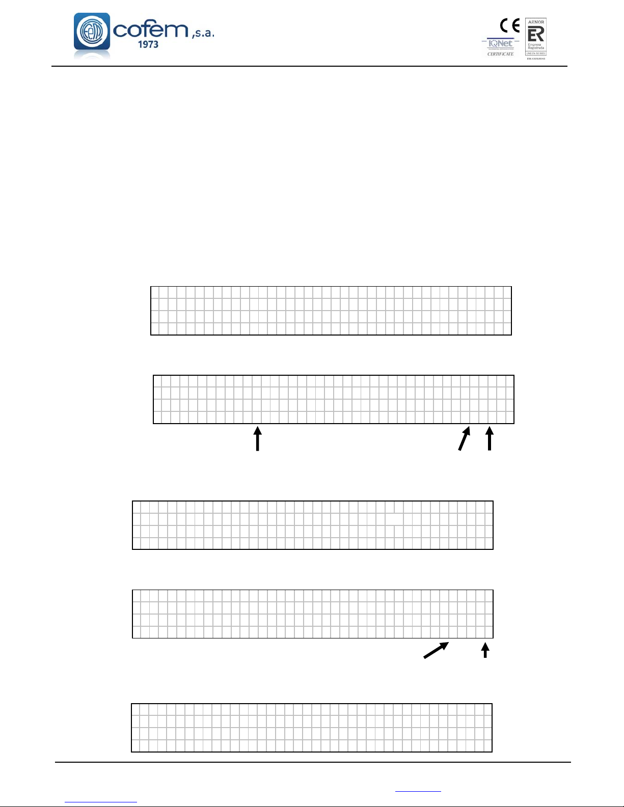
Digital fire detection control panel
LYON
FIRE PROTECTION MANUFACTURER
Ctra. de Molins de Rei a Rubí, Km. 8,4 - 08191 RUBÍ (Barcelona) ESPAÑA.
Tlf.: +34 935 862 690 - Fax:+34 936 999 261 - [email protected] - www.cofem.com 49
3.2.1.2. Incident and anomaly display.
Incidents and anomalies appear on the screen following this order of priority:
Alarms
Relays on
Faults
Disabled zones and points
Test Mode Events
Alarms
If an alarm takes place, the control panel will illuminate the red ALARM LED, sound the buzzer and
show the following screen.
In order to be able to select from amongst the different alarms, we must move using the up and down
cursors. The first line of the alarm corresponds to the selected alarm, whereas the second field refers to
the last alarm received.
A
LARMS TYPE:
01>LABEL MCPT
01
⁄
01
If the right cursor is pressed we will be able to see the rest of the alarm information.
Unit Loop POINT
A
LARMS C:B:Pt:
01>Z: 001 LABEL 01 01 006
<<01
⁄
02
Nº of alarmed zone Selected alarm Nº alarms
Relays on
If the control panel actuates a relay, it will illuminate the amber RELAYS ON LED, sound the
buzzer and show the following message:
T
RIGGER RELAY:
01>LABEL ALARM RELAY
02 LABEL 006
>>01
⁄
02
If the right cursor is pressed we will be able to see the rest of the activation information.
Unit Loop Point Nº
T
RIGGER C: B: Pt :
01>LABEL -- -- --02 LABEL 01 01 006
>>01
⁄
02
Selected activation Nº alarms
Disabled zones and elements
In the case of disabling a elements or zone, the control panel will illuminate the amber DISABLED
LED, sound the buzzer and show the following message:
C
ANCEL ED TYPE :
01>LABEL POINT CANCEL
02 ZONE 01 ZONE CANCEL
>> 01
⁄
02
Page 50
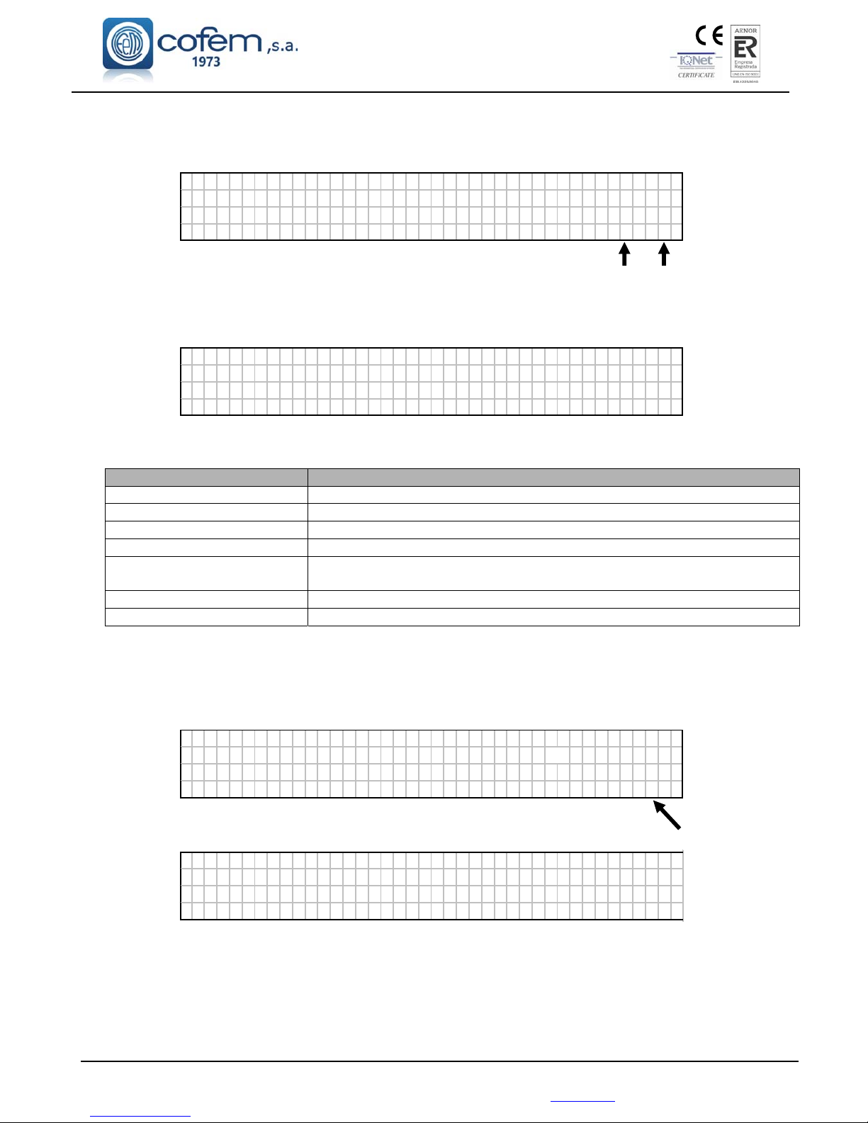
Digital fire detection control panel
LYON
FIRE PROTECTION MANUFACTURER
Ctra. de Molins de Rei a Rubí, Km. 8,4 - 08191 RUBÍ (Barcelona) ESPAÑA.
If the right cursor is pressed, we will be able to see the rest of the zone and/or element information.
Unit Loop Point Nº
C
ANCELED C:B:Pt:
01>Z: 001 LABEL 01 01 001
02 Z:001 LABEL -- -- ---
<< 01
⁄
02
Selected disabled item Nº disabled
Power supply faults
If the control panel detects a power supply failure, it will illuminate the amber GENERAL FAULT
and SUPPLY FAULT LEDs, sound the buzzer and show the following message.
F
AULTS TYPE :
01> SUPPLY CONTROL 11 EMPTY BAT
02 SUPPLY CONTROL 11 HIGH V NET
>> 01
⁄
02
Within supply faults, the following types of fault exist:
Type of Fault Description
30V
Fault in the 30V output
NO BATTERY
Battery fault due to or absence of batteries
CHARGER FAULT
Battery charger fault
FAULT CHARGER
Battery charger fault
BAT
OVERCHARGED
Battery fault due to high Voltage level.
HIGH VOLTAGE
Network Voltage fault due to exceeding the level
LOW VOLTAGE
Network Voltage fault due to low level or absence of the same
POINT faults
If the control panel detects a fault in any of the elements, it will illuminate the amber GENERAL
FAULT LED, sound the buzzer and show the following message.
F
AULTS TYPE :
01> LABEL PNT NO ANS
W
ER
02 LABEL OC RELAY 0 2
>> 01
⁄
02
Relay number
If the right cursor is pressed we will be able to see the rest of the fault information.
F
AULTS C:B:Pt:
01>Z: 001 01 01 001
02 Z : 003 01 01 003
>> 01
⁄
02
Page 51
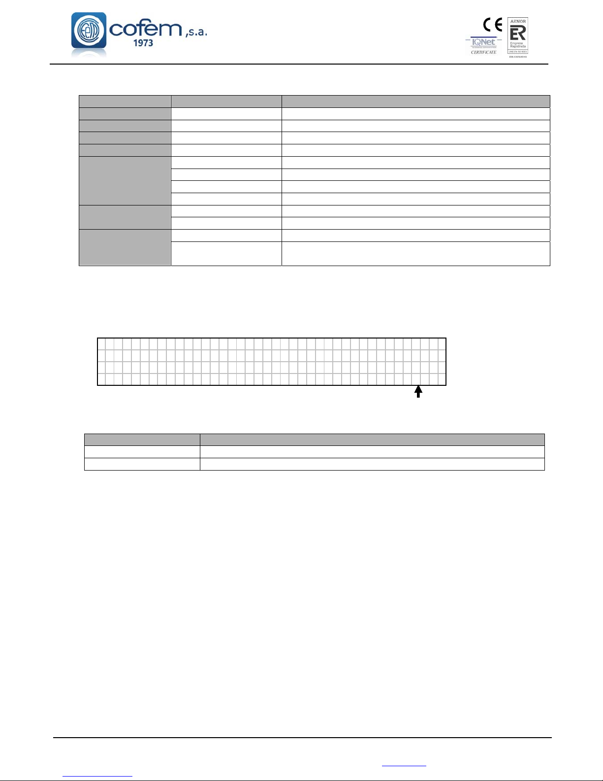
Digital fire detection control panel
LYON
FIRE PROTECTION MANUFACTURER
Ctra. de Molins de Rei a Rubí, Km. 8,4 - 08191 RUBÍ (Barcelona) ESPAÑA.
Tlf.: +34 935 862 690 - Fax:+34 936 999 261 - [email protected] - www.cofem.com 51
Within point faults the following types of fault exist:
Type of fault Description
All points POINT NO REPLY
Communication fault with point.
A30XHA DIRTY SENSOR
The A30XHA sensor has a dirty optical camera.
A30XHA-S DIRTY SENSOR
The A30XHA-S sensor has a dirty optical camera.
A30XHTCO DIRTY SENSOR
The A30XHTCO sensor has a dirty optical camera.
MDA1Y MDA2Y
MYOA
SC RELAY (Nº)
Short circuit in logical relay.
OC RELAY (Nº)
Open circuit in logical relay.
24V RELAY (Nº)
Absence of 24V in the relay module.
RELAY NOT ACTIV.
It has not been possible to activate the relay.
MSTAY MYOA
SC INPUT
Input short circuit
OC INPUT
Input open circuit
KMAY
CROS LIN MASTER
Short circuit in the zone of the master module.
OP LIN MASTER
Open master circuit (the circuit is not closed with a line
terminating condenser).
General siren faults
If the control panel detects a fault in one of the two general supervised outputs of the power supply,
the GENERAL FAULT amber LED lights, the buzzer will sound and display the following message:
F
AUL TS T I PO :
01>SUPPLY CONTROL AC RELAY: 10
0 2 SUP P L Y CONT RO L OC RE L A Y : 3
01
⁄
02
Relay number
The relay number indicates, in this case, which of the two outputs is at fault (R1 and R3 marked as
01 and 03). Within the general outputs faults there are these types of faults:
Type of fault Description
SC RELAY (Nº)
Short circuit in the general soundern relay or general fault relay
OC RELAY (Nº)
Open circuit in the general sounder relay or general fault relay
3.2.1.3.- Moving through incidents.
Once the control panel has displayed any of the incidents described above, the user will be able to
move among them using the “up and down” cursors and with the right cursor we will be able to see more
information about the selected incident.
Incidents of the same type are always displayed on the screen in chronological order. On the screen,
we have a maximum of two incidents. The incident that appears in the lower part of the screen is the last
incident that has taken place and the incident in the upper part is the selected one, which we can change with
the up and down cursors.
In order to change the type of incident on the screen we must press the ENTER key.
3.2.1.4. - Look up incidents.
After viewing the incident that we wanted to look up, we press the right cursor to obtain in each case
the corresponding screen with the rest of the incident information.
The next step, after viewing the incident and pressing the ENTER key, is to enter the level 2 access code.
Once in level 2, we will press RESET and the control panel will enquire if we want to reset the incident. The
access code 2 will remain active for a few seconds. If we exit level 2 access and the time of authorisation at
this level expires, it will be necessary to re-enter the corresponding code.
Page 52
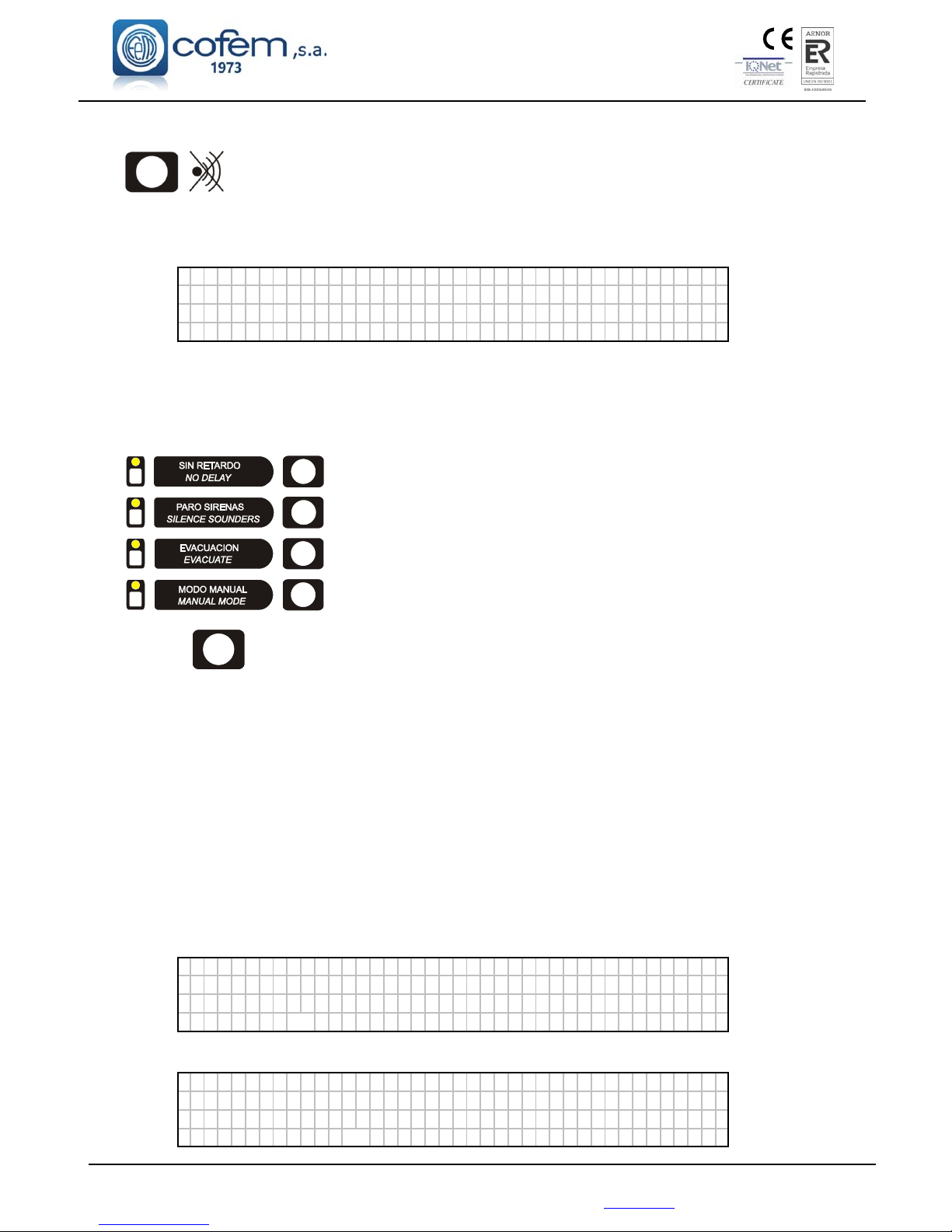
Digital fire detection control panel
LYON
FIRE PROTECTION MANUFACTURER
Ctra. de Molins de Rei a Rubí, Km. 8,4 - 08191 RUBÍ (Barcelona) ESPAÑA.
3.2.1.5.- Silence buzzer.
Key that enables the buzzer sound to be stopped after it has been activated by an
incident. It is automatically reactivated for each new incident.
3.2.2. - Level 2 access.
3.2.2.1. - Access code.
Pas swo r d Le v e l 2 : 00
When pressing the menu key we access level 2 by means of a code (027). At this new level we will
be able, among other things, to deactivate incidents, to put zones into service, to disable zones and to activate
and deactivate relays.
3.2.2.2.- Front panel keypad.
Disable configured relay delays.
Deactivate all relays that are configured as sirens.
Activate all relays programmed as sirens and switches.
Change to manual mode and disable all automatic activations of
relays.
RESET Key that enables the events generated in the system to be reset.
3.2.2.3.- Reset events.
After any of the incidents previously described have been detected and the access code to level 2 has
been entered, pressing the RESET key will deactivate these incidents, thereby resetting them. If these
incidents were faults, before resetting we must ensure that they have been corrected, otherwise they will reappear on the screen.
3.2.2.4.- Monitor.
Option 1 of the main menu, MONITOR. It enables the readings and the configuration of the various
analogue sensors to be seen. By entering the loop and elements numbers, we can see the type (optical,
thermal, relays module, master module, etc), the label and the manufacturer’s programming number. In the
case of optical and thermal sensors we will also see the last five measurements.
Monitor message of an optical sensor:
L
ABEL Ty p e : A30XHA
Loop : 001 Ad r ess : 001 S.Num. : 55826
Val ues : [ 000 000 000 000 ] Temp : 025
Di
r
t:000% Average : 000 Sens i t i b :MED
In the case of a thermal sensor, the values are monitored in degrees.
L
ABEL Ty pE : A3 0XTA
LOOP: 001 Adres s : 001 N. Pr og : 55826
Val ues : [ 025 025 025 025 ] Temp : 025
Di
r
t: ---% Average : 000 Sens i t i v :MED
Page 53
Digital fire detection control panel
LYON
FIRE PROTECTION MANUFACTURER
Ctra. de Molins de Rei a Rubí, Km. 8,4 - 08191 RUBÍ (Barcelona) ESPAÑA.
Tlf.: +34 935 862 690 - Fax:+34 936 999 261 - [email protected] - www.cofem.com 53
When monitoring, the third line describes the type of element according to the following table:
TYPE OF ELEMENT SCREEN DESCRIPTION
PUCAY MANUAL CALL POINT
A30XHTCO MULTI-SENSOR
SIRAY / SIRAYL ANALOGUE SIREN
A30XHA THERMAL OPTICAL SENSOR
A30XHA-S OPTICAL SENSOR
MDA1Y MASTER FOR ONE RELAY
MDA2Y DOUBLE RELAY MASTER
MSTAY TECHNICAL SIGNALS MASTER
KMAY ANALOGUE MASTER
MYOA MASTER RELAY AND TECHNICAL
SIGNALS
3.2.2.5.- Activate / Deactivate logical relays.
Option 2 of the main menu, LOGICAL RELAYS ACTIVATION. In this menu we have 5 submenus:
LIST TRIPPED RELAYS, ACTIVATE A SINGLE RELAY, DEACTIVATE A SINGLE RELAY,
ACTIVATE ALL SIRENS,ACTIVATE ALL SWITCHES.
Exactly as they suggest, the submenus enable us to activate groups of relays configured as switches
and sounders or make individual activations. Also there is the option to deactivate relays individually.
3.2.2.6.- Activate / Deactivate general relays.
Option 3 of the main menu, GENERAL RELAYS ACTIVATION. In this menu we have 2
submenus: GENERAL SIREN RELAY, FAULT RELAY. Within each of these we have 5 options:
ACTIVATE RELAY, DEACTIVATE RELAY, CHANGE DELAY, DISABLE RELAY and ENABLE
RELAY.
Exactly as they suggest the submenus enable us to activate or deactivate the relay, to configure its
delay between 0 and 9 minutes 59 seconds, and disabling or enabling the relay.
3.2.2.7.- System configuration.
Option 4 of the main menu, SYSTEM CONFIGURATION. From this option after entering the
password for level 3 access we are able to access the configuration menu. See chapter 3.2.3.
3.2.2.8.- Enable/ Disable elements and zones.
Option 5 of the main menu, PUT ZONES INTO/OUT OF SERVICE. In this menu we have 5
submenus: PUT POINT INTO SERVICE, SET POINT OUT OF SERVICE, PUT ZONE INTO
SERVICE, SET ZONE OUT OF SERVICE and LIST OUT OF SERVICE ZONES
Exactly as they suggest the submenus enable us to enable/disable zones or elements individually, and
to view a list of the out of service zones.
3.2.2.9.- System test.
Option 6 of the main menu, SYSTEM TEST. This is an option that allows us to perform a test of the
control panel indicators. In this test all LED should be illuminated, the buzzer should sound and the
following screen be shown:
█
███████████████████████████████████████
████████████████████████████████████████
████████████████████████████████████████
███████████████████████████████████████
█
Page 54
Digital fire detection control panel
LYON
FIRE PROTECTION MANUFACTURER
Ctra. de Molins de Rei a Rubí, Km. 8,4 - 08191 RUBÍ (Barcelona) ESPAÑA.
3.2.2.10.- Welcome message
Option 7 of the main menu. From this option it is possible to change the welcome message. The
welcome message is the text that appears on the first line when the control panel is in standby. This
message can have a maximum of 40 characters, which we will enter by means of the control panel cursors
or an external keyboard.
3.2.2.11. - General reset.
Option 8 of the main menu. From this option it is possible to reinitialise the whole system. When
resetting the system all the control panel events are deleted, that is to say, alarms, faults and actuations. It
maintains the state of the out of service elements and/or zones.
3.2.2.12. - Review history
Option 9 of the main menu. In this menu we have 5 submenus: REVIEW COMPLETE HISTORY,
REVIEW ALARMS, REVIEW FAULTS, REVIEW DISABLED ITEMS and REVIEW RELAYS.
By means of the up and down cursors we will move through the various stored events. The events
are stored in chronological order from the most recent to the oldest, storing a maximum of 4095 events. Once
4095 events are stored, the control panel will automatically delete the oldest in order to store a new event.
Review complete history: This enables each of the incidents detected by the control panel to be
reviewed, understanding by incident: disabled alarms, faults, zones and elements and actuations of
relays.
Review alarms: This submenu is the same as the one to review the complete history except that is
exclusively for alarms.
Type of event Alarm type
N
UM: 003 ALARM CALL POI NT
LOOP: 01 POINT: 005 N.Pr og : 00001
ZONE : 01 C . PANE L : 0 1 01 ⁄ 01 ⁄ 07 12 : 01
LABEL : B : 1 P : 5 NS : 1
Review faults: This submenu is the same as the one to review the complete history except that is
exclusively for fault.
Type of event Alarm type
N
UM : 0 0 3 FA U L T RE L A Y SC
LOOP: 03 POINT: 003 N.Pr og : 00003
ZONE : 01 C . PANE L : 0 1 01 ⁄ 01 ⁄ 07 12 : 01
LABEL : B : 3 P : 3 NS : 3
Review disabled items: This submenu is the same as the one to review the complete history except
that is exclusively for disabled items.
Type of event Alarm type
N
UM:001 DISABLED DIS. ELEMENT
LOOP: 01 POINT: 001 N.Pr og : 00120
ZONE : 01 C . PANE L : 0 1 01 ⁄ 01 ⁄ 07 12 : 01
LABEL: B : 1 P : 1 NS : 1 2 0
Page 55
Digital fire detection control panel
LYON
FIRE PROTECTION MANUFACTURER
Ctra. de Molins de Rei a Rubí, Km. 8,4 - 08191 RUBÍ (Barcelona) ESPAÑA.
Tlf.: +34 935 862 690 - Fax:+34 936 999 261 - [email protected] - www.cofem.com 55
Review relays: This submenu is the same as the one to review the complete history except that is
exclusively for relays.
Type of event Alarm type
N
UM : 0 0 4 AC TU
ION001 SELF ACT IV
LOOP: 03 POINT: 002 N.Pr og : 00002
ZONE : - - C . PANE L : 0 1 0 1 ⁄ 01 ⁄ 07 12 : 01
LABEL : B : 3 P : 2 NS : 2
3.2.3- Level 3 access.
3.2.3.1- Access code.
When entering the SYSTEM CONFIGURATION menu, we gain access to level 3 by means of a
code (9000). From this menu we can configure the whole system.
3.2.3.2.- Label elements.
Option 1 of the SYSTEM CONFIGURATION menu. We will have to introduce the loop and
element number to label. This is an option that allows us to label each element of the system, that is to say, to
give each point a description that gives us the information necessary to physically locate it in the installation.
The label can have a maximum of 20 characters. This is the screen that appears during the labelling process:
E
NTER TEXT :
OFF I CE
MENU - >COPY RESET - >PASTE ENTER- >ACCEPT
In order to introduce the label we can use the control panel cursors or an external keyboard.
3.2.3.3.- Configure.
Option 2 of the SYSTEM CONFIGURATION menu.
3.2.3.3.1.- Loop configuration.
Option 1 of the CONFIGURE menu. In this menu we have the possibility of configuring all the
parameters related to the element of a loop such as: to assign the element numbers, to detect the elements, to
configure sensitivity, etc.
Within the LOOP CONFIGURATION menu we have three important submenus that are:
SENSITIVITY OF A TYPE: This submenu allows us to vary the sensitivity of all the
sensors configured in the loop according to the type. Sensitivity has three levels HIGH,
AVERAGE and LOW (all the sensors come with average sensitivity).
FLASHING: This submenu allows us to enable/disable the blinking of all the elements
configured in the loop.
POINT CONFIGURATION: In this submenu we will be able to detect the elements that
are connected to the loop and to assign a point number to them. Within this submenu we
have seven submenus:
VIEW LOOP INFORMATION: In this submenu we can see the number of elements
that are in the loop classified by type.
L
OOP : 0 1 A 3 0 X H A ⁄ S:004 SIRAY:000
POINTS: 005 A 3 0 XTA : 000 MDAxY: 000
A3 0XHTCO:000 MSTAY:000
MYO
A
: 000 PU CAY:001 KM
A
Y:000
Page 56

Digital fire detection control panel
LYON
FIRE PROTECTION MANUFACTURER
Ctra. de Molins de Rei a Rubí, Km. 8,4 - 08191 RUBÍ (Barcelona) ESPAÑA.
SEARCH FOR LOOP POINTS: It detects elements in the installation and it shows a
list the same as the one above.
ASSIGN NUMBER TO POINT: To save the programming number of each point in
the control panel. The programming number is the identification number that each
elements has (from 1 to 65533 and the same number may never be repeated in a
loop). The control panel must know this programming number to identify the
elements.
AUTOMATIC LOOP SETUP: Find the points of the loop and assigns a setup number
to each point in order of programming numbers starting with the smallest.
DELETE POINT: To delete a point that is no longer connected to the loop and is still
configured, delete the programming number and the label of the element.
REPLACE POINT: Replace one point in the loop by another. This is the appropriate
option to replace an element since it saves the label. Take into account that it is
necessary to first physically replace the element with the control panel disconnected,
then start up the control panel and lastly run this menu option
DELETE LOOP POINTS: To eliminate all the points configured in a loop both
programming numbers and labels.
3.2.3.3.2.- Configure logical relays.
Option 2 of the CONFIGURE menu. In this menu we have the option of configuring all the
parameters referred to logical relays connected to the loop, that is to say, the type of actuation, delay, etc.
Within the CONFIGURE LOGICAL RELAYS menu we have eight submenus:
RELAY ACTUATION: The relays can be configured as Sounders, Switches and relay.
SOUNDERS: these are activated automatically if they have been so configured and
this is affected by the silence sounders button.
MANOEUVRES: these are activated automatically if they have been so configured
and are not affected by the silence sounders button
Crossed Relay L: this is activated automatically when there is 2 devices in alarm
inside its activation List. It is not affected by the silence sounders button neither
evacuation button.
Crossed Relay SL: this is activated automatically when there is 2 devices in alarm
inside one of its activation Sub-List. It is not affected by the silence sounders button
neither evacuation button.
NOTE: There is a manual call point version PUCAYEXT. This device is computed
by control panel as the acivation of two devices. In this way, it allows triggering the
rossed Relay L and Crossed Relay SL only activating this device.
RELAY: this is activated automatically and neither the evacuation nor the silence
sounders keys affect it.
DELAY: The time period within which the necessary alarms are generated in order for a
logical relay to be activated and the actuation of the same. A delay of between 0 and 9
minutes 59 seconds is possible.
DAY/ NIGHT: In this submenu we can configure the type of activation of a logical relay
(active with or without delay, inactive) for a daytime and night schedule. We will be able to
activate the day mode independently for every day of the week.
PHYSICAL SITUATION: Loop and point number where the logical relay is.
LABEL: To introduce a description of the relay for its identification in the installation.
ACTIVATION MODE: Within this menu we find two options: General Activation and
Activation by List.
GENERAL ACTIVATION: This option causes the relay to activate when an alarm
occurs in any element of the control panel.
ACTIVATION BY LIST: We can configure the activation lists of the relay selecting the
points that we want to activate the relay. When any one of the point defined in the list
goes into alarm status, the relay activates. The control panel enables up to 8 different
Page 57
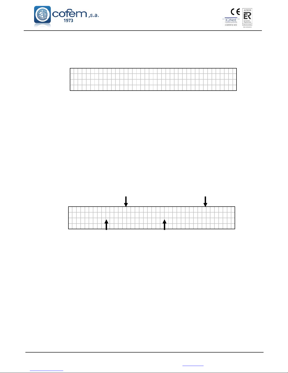
Digital fire detection control panel
LYON
FIRE PROTECTION MANUFACTURER
Ctra. de Molins de Rei a Rubí, Km. 8,4 - 08191 RUBÍ (Barcelona) ESPAÑA.
Tlf.: +34 935 862 690 - Fax:+34 936 999 261 - [email protected] - www.cofem.com 57
activation lists to be configured for each relay and they are configured by introducing a
first and last point (the points that are configured in the list are the all elements
consecutively from the first to the last entered point) in the same loop, except for the
crossed relay function which does not allow for activation lists.
VIEW CONFIGURATION: View the configuration of the relay and all its parameters.
R
ELAY: Re l ay Maneuve r Re l ay 002
MDA2Y Maneuve r Loop : 002 Po i n t : 003
DAY De t ec t o r : Ye s Ca l l : Yes De l a y : 00
NIGHT Det ec to
r
:Yes Cal l :Yes
VIEW DELAY LISTS: View the list of points configured for the relay.
3.2.3.3.3.- Configure alarm zones.
Option 3 of the CONFIGURE menu. In this menu we have the option of configuring the various
alarm zones into which we will divide the points of the control panel. When an alarm zone is
configured, it is not permissible to include a point in two different alarm zones.
Within this menu we have five submenus:
CONFIGURE ZONE: The control panel will request the loop number, the first and last
consecutive element included in the alarm zone list. We will be able to introduce 8 lists into
each alarm zone.
MODIFY LISTS: This option allows us to modify one of the alarm zone lists.
DELETE ZONE: The zone configuration is deleted.
LABEL: This provides a description of the zone with a maximum of 20 characters for its
identification in the installation.
VIEW CONFIGURATION: To view the list of points that are included in the alarm
zone.
Label Zone number
Z
ONE: B1 DET 1Y2 . ZONE: 001
B01 : P001 - 0 02 B01 : P006 - 006
Zone List Zone List
3.2.3.3.4.- Configure element sensitivity.
Option 4 of the CONFIGURE menu. From this menu we can vary the sensitivity of the points
individually (indicating the loop and point number). There are three levels of sensitivity: HIGH, MEDIUM
AND LOW (all the sensors come with average sensitivity).
3.2.3.3.5.- Additional passwords.
Option 5 of the CONFIGURE menu. From this menu we can introduce an additional password for
the access level 2 and another one for the access level 3, except the numbers 00 and 0000. Whenever we
introduce a new password it deletes the one that had been previously entered. The standard Passwords that
the control panel have are: access level 2: 27; and access level 3: 9000).
3.2.3.3.6.- Configure auto-evacuation.
This is option 6 of the CONFIGURE menu. Within this menu we have four submenus: ENABLE
AUTOEV., DISABLE AUTOEV., CONFIGURE DELAY and AUTO EVACUATION SUMMARY.
Automatic evacuation is a function that activates the relays configured as sounder and/or switches if there is
an alarm in the system and the alarm has not been reset during the configured delay.
Page 58

Digital fire detection control panel
LYON
FIRE PROTECTION MANUFACTURER
Ctra. de Molins de Rei a Rubí, Km. 8,4 - 08191 RUBÍ (Barcelona) ESPAÑA.
ENABLE AUTOEV.: Automatic evacuation is activated by this option.
DISABLE AUTOEV.: Automatic evacuation is deactivated by this option.
CONFIGURE DELAY: The delay period that occurs between the alarm being raised and the
siren and/or switch relays being activated is configured with this option. The maximum
delay is 9 minutes and 59 seconds.
AUTO EVACUATION SUMMARY: In this option we will be able to see the status of
automatic evacuation and its delay.
3.2.3.3.7- Added Delay Setup
This is option 7 of the CONFIGURE menu. This option is activated when it is introduced a time
between 1" to 9 min 59". When the first signal alarm is received, control panel actives corresponding
programmed delays. If operator press "Silence Buzzer" before programmed delay time is finished, all the
relays (including the sounder relay output in control panel) are additionally delayed with the value
"Additional delay". In this way, operator is allow to investigate alarm. If in any moment of the delays there is
a second signal alarm, all relays are activated immediately.
3.2.3.3.8- Fast Trigger Zone
This is option 8 of the CONFIGURE menu. The alarm signal input of any element defined in the zone
introduced in this option makes immediately activation of all control panel relays.
3.2.3.3.9- Send Zones to Repeaters
This is option 9 of the CONFIGURE menu. This option allows sending the configured zones to the
repeaters, of not realising it, the repeaters will only indicate the label of the point.
3.2.3.4.- Update date and time.
This is option 3 of the SYSTEM CONFIGURATION menu. Within this menu we have two options,
CHANGE DATE and CHANGE TIME. With the cursors we will be able to update the fields for both
options.
3.2.3.5.- Day/ Night times.
This is option 4 of the SYSTEM CONFIGURATION menu. Within this menu we have 5 submenus:
DAY TIME START, DAY TIME END, PROG. NIGHT MODE DAYS, DELETE NIGHT MODE PROG.
and PROGRAMMING SUMMARY.
The day/night mode serves to configure the activations of relays since they can have a different
operation for day and night. The day mode can be activated or deactivated independently for the different
days of the week.
DAY TIME START: The control panel will request the start time for the day mode.
DAY TIME END: The control panel will request the end time for the day mode.
PROG. NIGHT MODE DAYS: This option allows us to configure the control panel night
mode for the whole 24 hours of a day.
DELETE NIGHT MODE PROG.: This option deletes the configuration described in the
previous paragraph
PROGRAMMING SUMMARY: This option shows us the configuration of the night mode
day for the control panel.
3.2.3.6.- Put into test/ normal mode.
This is option 5 of the SYSTEM CONFIGURATION menu. Within this menu we have 3 submenus:
TEST MODE, NORMAL MODE and LIST ZONES.
Page 59

Digital fire detection control panel
LYON
FIRE PROTECTION MANUFACTURER
Ctra. de Molins de Rei a Rubí, Km. 8,4 - 08191 RUBÍ (Barcelona) ESPAÑA.
Tlf.: +34 935 862 690 - Fax:+34 936 999 261 - [email protected] - www.cofem.com 59
Test mode is the operating mode that allows us to activate the alarm of any control panel element
without any of the configured relays activating. In addition all the alarms will reset automatically after 15
seconds. This mode is appropriate for performing tests and system maintenance.
TEST MODE: Within this menu we have two options: we will be able to activate test mode
generally or by alarm zone.
NORMAL MODE: Within this menu we have two options: we will be able to activate
normal mode generally or by alarm zone.
LIST ZONES: This option shows us the operating mode of the control panel and the alarm
zones.
3.2.3.7- Led ON / OFF.
This is option 6 of the SYSTEM CONFIGURATION menu. This menu allows activation or
desactivation (If it is already activated) the led of one element of the loop. This functionality is actived if the
element is inside a zone in test mode.
3.2.3.8.- Language menu.
This is option 7 of the SYSTEM CONFIGURATION menu. From this menu the language of the
control panel is selected. The control panel will be provided with seven languages as standard: Spanish,
English, French, Italian, Hungarian, Russian Ukrainian and Portuguese.
3.2.3.9.- Communications.
This is option 8 of the SYSTEM CONFIGURATION menu. Within this menu we have following
submenus:
NETWORK OF REPEATERS:
VIEW CONFIGURED REPEATERS: display the configured repeaters on the control panel.
CONFIGURE REPEATERS: Give the address of the repeaters with which it is desired to
communicate.
AUTO-DETECT SLAVES: In this menu the connected repeaters are detected and the control panel
will automatically communicate with these repeaters.
ERASE REPEATER: From this option the selected repeater is deleted.
DELETE REPEATERS: From this option, all the repeaters configured in the control panel are
deleted.
LABEL REPEATER: In this menu we give a label to the repeater with a maximum of 20
characters.
INTERNAL NETWORK:
SEE CONTROL PANELS: Visualize the configured control panels.
RESET CONTROL PANEL NETWORK: Reset all the control panels connected to a network.
SPECIAL FUNCTIONS:
NO DELAY: Activate or deactivate all the delays of all the relays associated to all the
control panels of the network.
STOP SIRENS: Activate or deactivate the sirens stop of all the sirens associated to all the
control panels of the network.
EVACUATION: Activate or deactivate all the relays associated to all the control panels of
the network.
MANUAL MODE: Activate or deactivate the manual mode in all the control panels of the
network.
CONTACTID
ACTIVATE
DEACTIVATE
TEST INTERVAL
Checking time of the communication with the receiving center.
Page 60
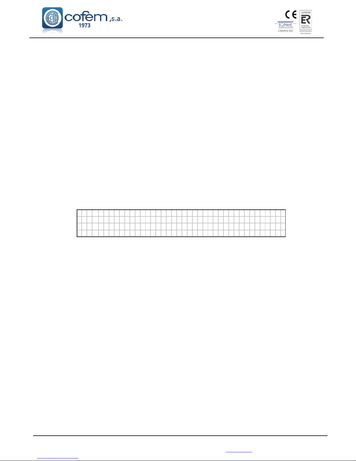
Digital fire detection control panel
LYON
FIRE PROTECTION MANUFACTURER
Ctra. de Molins de Rei a Rubí, Km. 8,4 - 08191 RUBÍ (Barcelona) ESPAÑA.
PHONE 1 NUMBER PROGRAMING
PHONE 2 NUMBER PROGRAMING
PHONE 3 NUMBER PROGRAMING
PHONE 4 NUMBER PROGRAMING
PHONE 5 NUMBER PROGRAMING
SITUATION MESSAGE PROGRAMING
Message sent to the phones configured in the previous options
CONFIGURE CONTROL PANEL NUMBER:
SET CONTROL PANEL NUMBER.
CONTROL PANEL NUMBER:
VISUALIZE THE CONTROL PANEL NUMBER.
TYPE OF PC COMMUNICATION:
The communication ports of the control panel are configurable with the different available
functionalities. The control panel has 3 RS485 communications ports identified as CONPC
(COM1), CONRED (COM2), CONREP (COM3) and a USB port identified as USB (USB1). In
this menu you can select the port you want to use with the following features:
NeTW: Connection port for connecting control panels in network.
RePT: Connection port for connecting repeater.
iLNK: Connection port for control panel software configuration I-Link or I-Link ONLINE.
C_ID: Connection port for ContactID.
MoDB: Connection port for MODBUS.
ReMT: Connection port for REMOTE card.
C
ommu n i c a t i o n mo d e
NeTW:COM2RePT:COM3 iLNK:USB1
C_ I D : - - MoDB: - - ReMT : COM1
ENT ER : S
A
VE , OPT I ONS : UP - DOWN, ESC: OUT
INTERNAL NETWORK:
AUTODETECT CONTROLLERS: In this menu, all the connected controllers are
detected and configured. This function deletes the previously configured controllers.
ERASE LOOP CONTROLLER: Erase the selected loop controller from the
configuration of the control panel.
ERASE SUPPLY CONTROLLER: To erase the selected power supply controller
from the configuration of the control panel.
CONSULT VERSION: Check the software versions for the CPU circuit (control
panel version) and for the different loop controllers (controller version) which may
be connected.
REMOTE CONECTION:
It allows configuring the following communication parameters of the REMOTE card in the ethernet network.
IP: Defines the IP address of the REMOTE card in the internal network. By default
192.168.0.254.
PORT: Defines the port of the REMOTE card. The server / router must be configured to
allow communication between the REMOTE card and the external network. By default the
value is 80.
MASK: Mask of the server / router that differentiates the IP addresses of the internal and
external network. Based on the IP address of the server / router, the "0" values identify the
internal addresses. By default, the value of the mask is 255.255.255.0.
GATEWAY: IP address of the server / router. By default the value is 192.168.0.50.
UMIP: Acronym for "Update My IP". With the activation of this function, it is allowed to
communicate with the REMOTE card of the central from the web "www.l-remote.com"
automatically without needing to know the IP address of the server / router.
SERIAL NUMBER: It is the serial number of the REMOTE card needed to identify it on the
web "www.l-remote.com".
Page 61
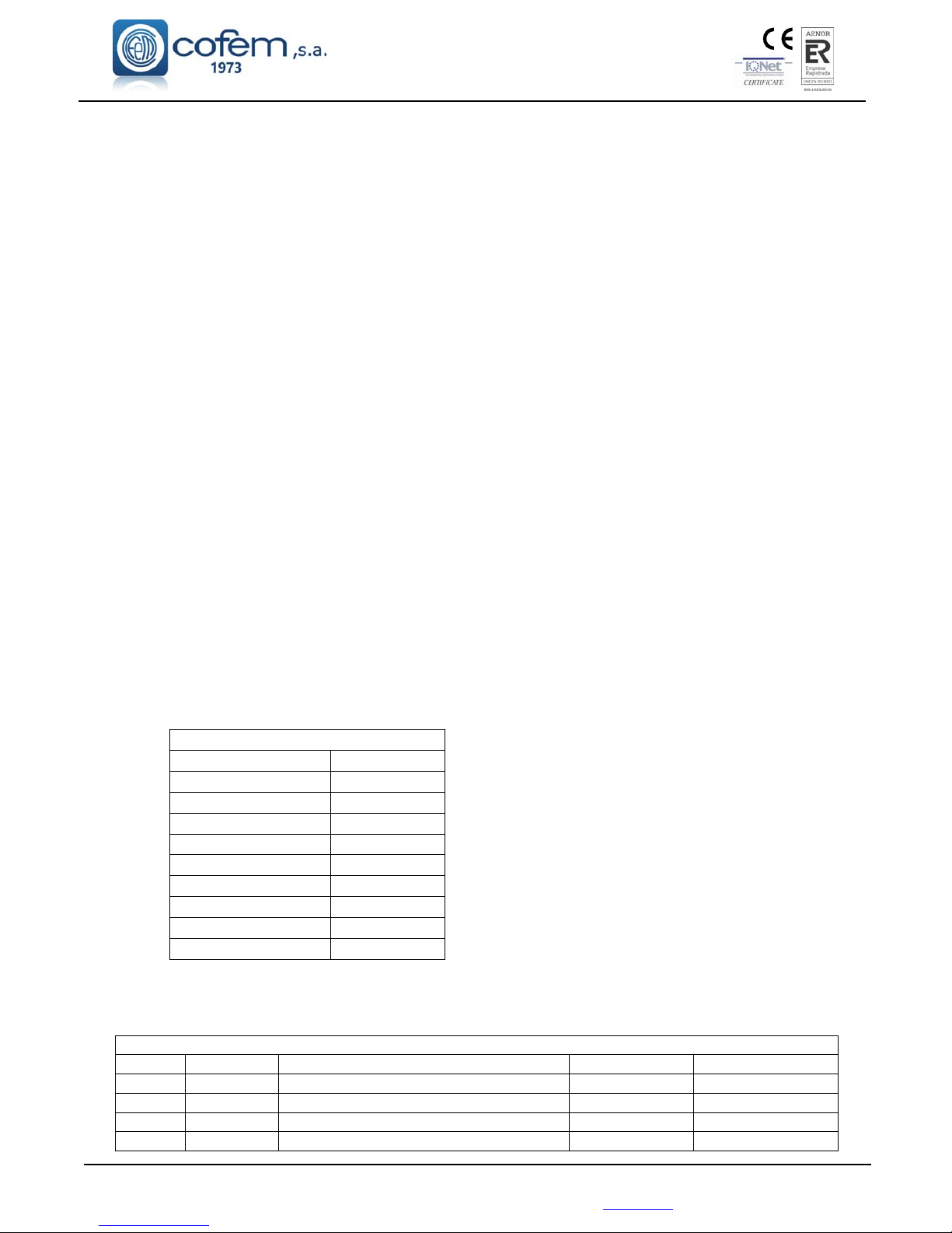
Digital fire detection control panel
LYON
FIRE PROTECTION MANUFACTURER
Ctra. de Molins de Rei a Rubí, Km. 8,4 - 08191 RUBÍ (Barcelona) ESPAÑA.
Tlf.: +34 935 862 690 - Fax:+34 936 999 261 - [email protected] - www.cofem.com 61
3.2.3.10.- Stop Sounder Function.
This is option 9 of the SYSTEM CONFIGURATION menu. Within this menu we have the following
options:
ACTIVATION:
CONTINUOUS: "Stop Sounder" continues active after re-start up of the control panel.
RESET: "Stop Sounder" is automatically desactivated after re-start up of the control panel.
PERFORMANCE:
CONTINUOUS: "Stop Sounders" continues active although new signal alarm arrives to
control panel.
EVENT: "Stop Sounders" is deactivated when new signal alarm is received to control panel.
VIEW SET UP:
It is shown selection of "ACTIVATION" and "PERFORMANCE".
4.- Set-up.
4.1.- Prior verifications.
Prior to putting the Lyon analogue system installation into operation, we must assure ourselves that
the installation is totally completed and we have all the data for its correct programming. For this it is
necessary to verify that the points shown below have been completed:
To have a 110~230V power source available dedicated to the fire protection system and that it is live
24 hours a day, seven days a week. (see chapter 2.1)
To have a set of two 12V batteries with a capacity between 7 and 24Ah depending on the number of
loops and load connected to the control panel. (to see chapter 2.3.1)
To verify that all the elements are connected to the installation.
To verify that there are no installation elements left unconnected or with connection errors that could
cause faults when putting into operation or deterioration of the Lyon analogue system elements.
Do not remove the covers until the installation is finished and clean.
To have a list with the total of connected elements of each type in each loop, see example in the
following table.
LOOP: 1
TYPE AMOUNT
A30XHA/S
25
A30XTA
2
A30XHTCO
47
PUCAY
36
SIRAY
3
MDAXY
6
MSTAY
1
KMAY
3
TOTAL
123
To have a list for each loop with the location, type and programming number of each element,
(sensor, button, relay module, technical signals module, analogue sirens, master module). This
programming number goes from 1 to 65533, see example in the following table:
Loop: 01
POINT Prog. No. Label Type Notes
1 12757 ROOM 101 A30XHA
2 12432 ROOM 102 A30XHA
3 4767 BUTTON P1 PUCAY
4 6982 CORRIDOR P1 KMAY
Page 62

Digital fire detection control panel
LYON
FIRE PROTECTION MANUFACTURER
Ctra. de Molins de Rei a Rubí, Km. 8,4 - 08191 RUBÍ (Barcelona) ESPAÑA.
In this way with the lists made on-site, that are completed with the listings of relay activation and
with the relationship of alarm zones, it is possible to undertake the system programming working with an
external keyboard, on the control panel’s own keypad or much more easily using the I-Link program on a
PC that will later download to the control panel.
4.2.- Supply
NETWORK: The power to the input terminals will be 110~230V +/- 10% - 50-60 Hz
Attention! Connect the EARTH cable, ensuring the right position of the neutral and phase line .
BATTERIES: Connect the two elements in series (Watch out for the polarity). In the presence of
network power the battery terminals will have between 24 and 28 V DC.
The 110~230V power supply will be connected to the Lyon control panel and then the batteries.
The green power supply LED on the front of the control panel must light and the initialisation texts must be
seen as indicated in section 3.2.1.1.
4.3.- Loops and relays
The loops will be put into operation one by one. Once the loop cables are connected to the
corresponding driver, proceed with the element search as described in section 3.2.3.4.1. or in the element
Configuration Manual.
When the search is completed check the number of elements found by the control panel against the data
taken previously, see section 4.1.
If the number found is the same, it means that all the elements are correctly connected to the Control
Panel Lyon system loop.
If the number found is higher it means that there must be more elements installed in the loop. You
must update the information about them – programming numbers, labels - to be able to complete the
putting on operation.
If the number found is lower, it means that fewer elements have been installed in the loop; there are
unconnected or not assembled loop elements. Review the whole loop installation reviewing all the
connections and counting the installed elements.
Once any problems in the system have been resolved, the loop element search must be repeated. If a
correct result is obtained, the entire process described above can be repeated for another system loop.
Next, one must proceed with the allocation of previously chosen programming numbers to the loop
elements, see section 4.1. For this they will be entered into the control panel by means of its keys (see
section, 3.2.3.4.1 or elements Configuration Manual), a PC keyboard (see section, 3.2.3.4.1 or Element
Configuration Manual) or by means of a computer, (see I-Link).
Also a name can be assigned to each loop element, called a label. It can be done from the control
panel keys, (see section 3.2.3.3 or Element Configuration Manual), a PC keyboard (see section 3.2.3.3 or
Element Configuration Manual) or by means of a computer, (see I-Link).
If the control panel has relay modules (MDA1Y, MDA2Y and MYOA) and loop sirens
(SIRAY/SIRAYL), one will proceed to the configuration of such depending on the elements that must
activate them, from the control panel keys, (see section, 3.2.3.4.2 or Element Configuration Manual), a PC
keyboard (see section, 3.2.3.4.2 or Element Configuration Manual) or by means of a computer, (see I-Link).
Optionally the Alarm Zones can be configured from the power station, (see section, 3.2.3.4.3 or
Element Configuration Manual), a PC keyboard (see section, 3.2.3.4.3 or Element Configuration Manual) or
by means of a computer, (see I-Link).
Once the previous steps are complete we must verify that the programming performed is correct. For
this we must monitor all the elements in all the loops of the control panel. This will be done from the control
panel keys, (see section 3.2.2.4 or Element Configuration Manual), a PC keyboard (see section 3.2.2.4 or
Element Configuration Manual).
Page 63
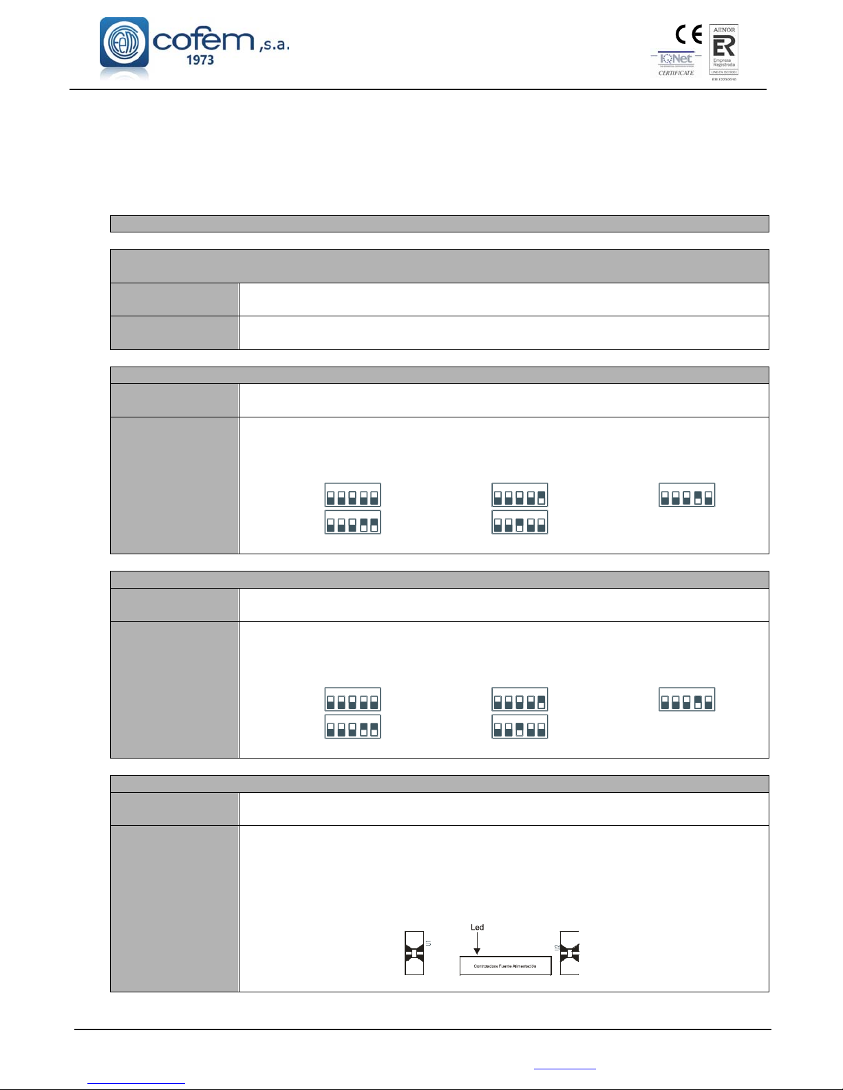
Digital fire detection control panel
LYON
FIRE PROTECTION MANUFACTURER
Ctra. de Molins de Rei a Rubí, Km. 8,4 - 08191 RUBÍ (Barcelona) ESPAÑA.
Tlf.: +34 935 862 690 - Fax:+34 936 999 261 - [email protected] - www.cofem.com 63
During the startup process, the control panel may display various types of faults. For the Lyon analogue
control panel to work correctly, these faults must be resolved. For this, consult section 4.4 which describes
the main faults, the causes of them and the action to be taken to resolve them.
4.4.- Faults
4.4.1.- FAULTS IN CONTROL PANEL STARTUP
THE CONTROL PANEL DOES NOT TURN ON (POWER SUPPLY AND BATTERY leds off, display
shows nothing)
Cause
Neither the 110~230V supply nor the batteries are providing the correct voltage to
the panel.
Solution
Check that there is 110~230V mains voltage in the terminal strip for connecting the A.C.
source. Connect fully charged 24V batteries (between 24V and 28V).
THERE ARE NO LOOP CONTROLLERS
Cause
During the control panel's start-up process, the panel does not find any Loop
Controllers.
Solution
Turn off the control panel, leave it for one minute, and start it up again. If the same
message is still displayed, check whether the controller has been mishandled, ensuring
that it is correctly inserted in the back panel, and that the micro-switches are configured as
in the following table:
Controller 1: Controller 2: Controller 3:
Controller 4: Controller 5:
Also consult section 3.2.1.1
CONTROLLER NOT FOUND WITH ADDRESS: 001 … 002 003 004 005
Cause
During the control panel's start-up process, the panel had not found the Loop
Controller with the number indicated.
Solution
Turn off the control panel, leave it for one minute, and start it up again. If the same
message is still displayed, check whether the controller has been mishandled, ensuring
that it is correctly inserted in the back panel, and that the micro-switches are configured as
in the following table:
Controller 1: Controller 2: Controller 3:
Controller 4: Controller 5:
Also consult section 3.2.1.1
CONTROLLER NOT FOUND WITH ADDRESS: 011
Cause
During the control panel's start-up process, the panel has not found the Power
Source Controller.
Solution
Turn off the control panel, leave it for one minute, and start it up again. If the same
message is still displayed, check whether the controller has been mishandled, ensuring
that it is correctly inserted in the back panel.
When it is operating correctly, the led mounted in this power source controller should be
flashing.
Consult section 3.2.1.1
1
234
5 1
234
5 1
234
5
1
2
3
45
1
2
3
45
1
2
3
45
1
2
3
45
1
2
3
45
1
234
5 1
234
5
242
Page 64
Digital fire detection control panel
LYON
FIRE PROTECTION MANUFACTURER
Ctra. de Molins de Rei a Rubí, Km. 8,4 - 08191 RUBÍ (Barcelona) ESPAÑA.
4.4.2.- POWER SUPPLY FAULTS
MAINS VOLTAGE DROPS (110~230V voltage does not reach the power source)
Cause
110~230V voltage does not reach the power source.
Solution
Check that there is 110~230V mains voltage in the terminal strip for connecting the A.C.
source. The green led of the A.C. source must be lit. Check the status of the power supply
fuse (8 Amps). (See chapters 2.2.1 and 2.2.3)
MAINS VOLTAGE TOO HIGH
Cause
110~230V power supply is outside the permitted range.
Solution
Check that there is 110~230V mains voltage in the terminal strip for connecting the A.C.
source. The green led of the A.C. source must be lit. (See chapters 2.2.1 and 2.2.3)
NO BATTERY (The battery is not connected to the control panel)
Cause
Either the battery is not connected to the control panel or it is connected incorrectly.
Solution
Check that the batteries are correctly connected to the control panel, and check the status
of the battery output fuse (5 Amps). Carefully examine the battery polarity and check that
they are connected in series. For normal operation, the voltage in the battery output, when
they are connected, should be between 22V and 28V. (See chapter 2.3.1)
BATTERIES OVERLOADED (The batteries do not accept a charge)
Cause
The batteries have reached the end of their useful life.
Solution
Replace the set of batteries with new ones. For normal operation, the voltage in the
battery output, when they are connected, should be between 22V and 28V. (See chapter
2.3.1)
BATTERIES DISCHARGED (The batteries are not charged)
Cause
The batteries are not charged, or they are not connected correctly.
Solution
Check that the two 12V batteries are connected in series, and wait for about 12 hours for
them to finish charging. If the fault persists, replace the batteries with new ones. For
normal operation, the voltage in the battery output, when they are connected, should be
between 22V and 28V. (See chapter 2.3.1)
CHARGER FAULT (The battery charger doesn't work)
Cause
The battery charger does not charge the batteries This message is associated with faults
mentioned above, such as: MAINS VOLTAGE DROP, NO BATTERY, BATTERIES
OVERLOADED and BATTERIES DISCHARGED. This message is displayed 4 minutes
after the fault occurs.
Solution
Check the batteries’ connections and status as indicated above. If this fault is indicated,
but there is no other associated message, checks the battery charger fuse (1 Amp). (See
chapters 2.2.1, 2.2.3 and 2.3.1)
30V FAULT (There is no 30V voltage at the 30V output from the Power Source)
Cause
The fuse for this output has blown due to a short circuit or excessive power consumption.
Solution
Check the connections for the 30V output and check how many elements, such as
repeaters, electromagnets, etc. are connected to it, in order to ensure that the maximum
permissible power consumption is not exceeded. (See chapters 1.5.4.1 and 2.2.3)
Page 65
Digital fire detection control panel
LYON
FIRE PROTECTION MANUFACTURER
Ctra. de Molins de Rei a Rubí, Km. 8,4 - 08191 RUBÍ (Barcelona) ESPAÑA.
Tlf.: +34 935 862 690 - Fax:+34 936 999 261 - [email protected] - www.cofem.com 65
RELAY OPEN CIRCUIT:01 (Open circuit for the S1 General Sounder relay)
Cause
There is a lack of continuity between the output of the S1 General Sounder relay and the
end-of-line resistance.
Solution
Check that S1 General Sounder output is correctly connected to the sounders connected to
it, check that the end-of-line resistance (4K7) and check the supervision diodes are
correctly mounted (see chapters 2.3.3.1 and 2.3.3.2). Check the status of the S1 output
fuse (2 Amps). To operate correctly, the S1 General Sounder’s output voltage must be
between -10V and -18V when in standby and between 24V and 29V when activated.
RELAY SHORT-CIRCUITED:01 (Short circuit for the S1 General Sounder relay)
Cause
There is a short circuit between the output of the S1 General Sounder relay and the endof-line resistance.
Solution
Check that S1 General Sounder output is correctly connected to the sounders connected to
it, check that the end-of-line resistance (4K7) and check the supervision diodes are
correctly mounted (see chapters 2.3.3.1 and 2.3.3.2). To operate correctly, the S1 General
Sounder’s output voltage must be between -10V and -18V when in standby and between
24V and 29V when activated.
RELAY OPEN CIRCUIT:03 (Open circuit for the S3 General Fault relay)
Cause
There is a lack of continuity between the output of the S3 General Fault relay and the endof-line resistance.
Solution
Check that the S3 General Fault output is correctly connected to the devices connected to
it, check that the end-of-line resistance (4K7) and the supervision diodes are correctly
mounted. Check the status of the S3 output fuse (1 Amp). To operate correctly, the S3
General Fault’s output voltage must be between +10V and +18V when in standby and 0V
when activated.
RELAY SHORT CIRCUIT:03 (Short circuit for the S3 General Fault relay)
Cause
There is a short circuit between the output of the S3 General Fault relay and the end-ofline resistance.
Solution
Check that the S3 General Fault output is correctly connected to the devices connected to
it, check that the end-of-line resistance (4K7) and the supervision diodes are correctly
mounted. To operate correctly, the S1 General Sounder’s output voltage must be between
+10V and +18V when in standby and 0V when activated.
4.4.3.- LOOP FAULTS
ELEMENT NOT RESPONDING
Cause
An element in the loop has stopped working.
Solution
Check that the element has not been removed from the installation, check that the element
is correctly connected and that the loop voltage reaching it is between 22V and 35V. Also
check that it has not been affected by external agents such as water leaks, etc.
If this fault affects several elements, check whether they are all between the same two
insulators. If this is the case, check that section of the installation, as there must be a short
circuit in the wiring.
Page 66
Digital fire detection control panel
LYON
FIRE PROTECTION MANUFACTURER
Ctra. de Molins de Rei a Rubí, Km. 8,4 - 08191 RUBÍ (Barcelona) ESPAÑA.
EXCESSIVE POWER CONSUMPTION
Cause
The loop is overloaded or has a short circuit; the voltage in the loop is below 22V.
Solution
Check the wiring for the affected loop, check for possible short circuits, check whether
there are elements connected to the loop that should not be directly connected to it, such
as: conventional detectors, end-of-line condensers or resistances, electromagnets,
sounders, etc. Also check that it has not been affected by external agents such as water
leaks, etc. Once the original cause of the fault has been located and resolved, wait 5
minutes before resetting the incident in the control panel, since the protection elements
need to cool down. For normal operation, the voltage in the loop should be between 22V
and 35V.
OPEN LOOP
Cause
The loop is not closed correctly.
Solution
Check wiring and connections of the affected loop.
CONTROLLER FOR LOOP: OX IS NOT COMMUNICATING
Cause
The controller for the indicated loop has stopped working.
Solution
Reset the control panel. If, during start-up, the following message is shown:
“CONTROLLER NOT FOUND WITH ADDRESS: 001 … 002 003 004 005”, stop the
control panel, disconnecting both the 110~230V power supply and the batteries, and
check that the controller is correctly inserted in the control panel’s back panel. Then start
the control panel up again. If the problem persists, please contact our Technical Services
Department.
OPEN CIRCUIT IN MASTER (Open Circuit in the KMAY master for conventional detectors)
Cause
There is a lack of continuity in the wires for the line of slaves from the KMAY to the end
of the line. The end-of-line is not mounted.
Solution
Check that the KMAY is correctly connected to the detectors and manual call points
which are connected to it. Check that the end-of-line 10uF-63V condenser is correctly
connected, and with the right polarity (see chapter 1.5.3.1). To operate correctly the
KMAY’s output voltage should be between 18V and 21V.
SHORT CIRCUIT IN MASTER (Short Circuit in the KMAY master for conventional detectors)
Cause
There is a short circuit in the connections from the KMAY to the end of the line.
Solution
Check that the KMAY is correctly connected to the detectors and manual call points
which are connected to it. Check that the end-of-line 10uF-63V condenser is correctly
connected, and with the right polarity, and check that the slave manual call points are
connected with the correct polarity (see chapter 1.5.3.1). To operate correctly the
KMAY’s output voltage should be between 18V and 21V.
RELAY OPEN CIRCUIT 01 (Open circuit for the relay 1 of the MDA1Y, MDA2Y or MYOA)
Cause
There is a lack of continuity between the output of the relay 1 of the MDA1Y, MDA2Y or
MYOA and the end-of-line resistance.
Solution
Check that the MDA1Y, MDA2Y or MYOA is correctly connected to the sounders
connected to it, check that the 33 K end-of-line resistance and the supervision diodes are
correctly mounted (see chapters 1.5.3.2, 1.5.3.3 and 1.5.3.7). Check the status of the fuse
protecting the module. To operate correctly, the output voltage of the relay 1 of the
MDA1Y, MDA2Y, MYOA must be between -2 V and -7,8 V when in standby and
between 24 V and 29 V when activated.
Page 67
Digital fire detection control panel
LYON
FIRE PROTECTION MANUFACTURER
Ctra. de Molins de Rei a Rubí, Km. 8,4 - 08191 RUBÍ (Barcelona) ESPAÑA.
Tlf.: +34 935 862 690 - Fax:+34 936 999 261 - [email protected] - www.cofem.com 67
RELAY SHORT CIRCUIT 01 (Short circuit for the relay 1 of the MDA1Y, MDA2Y or MYOA)
Cause
There is a short circuit between the output of the relay 1 of the MDA1Y, MDA2Y or
MYOA and the end-of-line resistance.
Solution
Check that the MDA1Y, MDA2Y or MYOA is correctly connected to the sounders
connected to it, check that the 33 K end-of-line resistance and the supervision diodes are
correctly mounted (see chapters 1.5.3.2, 1.5.3.3 and 1.5.3.7). To operate correctly, the
output voltage of the relay 1 of the MDA1Y, MDA2Y or MYOA should be between -2 V
and -7,8 V in standby and 24 V to 29 V when activated.
RELAY OPEN CIRCUIT 02 (Open circuit for the relay 2 of the MDA2Y)
Cause
There is a lack of continuity between the output of the relay 1 of the MDA2Y and the endof-line resistance.
Solution
Check that the MDA2Y is correctly connected to the sounders connected to it, check that
the 33 K end-of-line resistance and the supervision diodes are correctly mounted (see
chapter 1.5.3.2). Check the status of the fuse protecting the module. To operate correctly,
the output voltage of the relay 2 of the MDA2Y must be between -2 V and -7,8 V when in
standby and between 24 V and 29 V when activated.
RELAY SHORT CIRCUIT 02 (Short circuit for the relay 2 of the MDA2Y)
Cause
There is a short circuit between the output of the relay 2 of the MDA2Y and the end-ofline resistance.
Solution
Check that the MDA2Y is correctly connected to the sounders connected to it, check that
the 33 K end-of-line resistance and the supervision diodes are correctly mounted (see
chapter 1.5.3.2). To operate correctly, the output voltage of the relay 2 of the MDA2Y
must be between -2 V and -7,8 V when in standby and between 24 V and 29 V when
activated.
24V RELAY ( 24V Fault in module MDA1Y, MDA2Y or MYOA)
Cause
The 24 V voltage does not reach the module from the power supply’s 30 V output, which
may be from the control panel or from an auxiliary external power source.
Solution
Check the connections for the 30 V line from the control panel’s power source, or
auxiliary external power source, to the 24 V input to the MDA1Y, MDA2Y or MYOA
module, (see chapters 1.5.3.2, 1.5.3.3 and 1.5.3.3). To operate correctly, the 24 V voltage
input to the modules should be between 20 V and 29 V.
OC INPUT 01 (Open line in MSTAY input 1)
Cause
There is a lack of continuity between the input of the relay 1 of the MSTAY and the endof-line resistance.
Solution
Check the correct connection of the MSTAY elements connected to it, verify the correct
assembly of the end of line resistor, 33 K (see chapter 1.5.3.4.). The MSTAY voltage
input 1 for proper operation should be between -5 V and -7 V at rest.
SC INPUT 01 (Short circuit in MSTAY input 1)
Cause
There is a short circuit between MSTAY input 1 and the end of line resistor.
Solution
Check the correct connection of the MSTAY elements connected to it, verify the correct
assembly of the end of line resistor, 33 K (see chapter 1.5.3.4.). The MSTAY voltage
input 1 for proper operation should be between -5 V and -7 V at rest.
OC INPUT 02 (Open line in MSTAY or MYOA input 2)
Cause
There is a lack of continuity between the input 2 of the MSTAY or MYOA and the endof-line resistance.
Solution
Check the correct connection of the MSTAY elements connected to it, verify the correct
assembly of the end of line resistor, 33 K (see chapter 1.5.3.4 and 1.5.3.7). The MSTAY
and MYOA voltage input 2 for proper operation should be between -5 V and -7 V at
rest.
Page 68
Digital fire detection control panel
LYON
FIRE PROTECTION MANUFACTURER
Ctra. de Molins de Rei a Rubí, Km. 8,4 - 08191 RUBÍ (Barcelona) ESPAÑA.
SC INPUT 02 (Short circuit in MSTAY or MYOA input 2)
Cause
There is a short circuit between MSTAY or MYOA input 2 and the end of line resistor.
Solution
Check the correct connection of the MSTAY or MYOA elements connected to it, verify
the correct assembly of the end of line resistor, 33 K (see chapter 1.5.3.4 and 1.5.3.7).
The MSTAY and MYOA voltage input 2 for proper operation should be between -5 V
and -7 V at rest.
TECHNICAL FAULT (IN2 input to the MSTAY has been activated)
Cause
A signal which is external to the analogue detection system has activated the MSTAY IN2
input.
Solution
This is not a fault in the analogue detection system, in fact this is how it should normally
work. Check the operating status of the devices connected to the MSTAY (IN2). (see
chapter 1.5.3.4)
DIRTY SENSOR
Cause
The permitted level of dirt has been exceeded on the sensor (A30XHA, A30XHAS and
A30XHTCO), 100% in the monitoring screen, the sensor must be cleaned.
Solution
Clean the sensor using compressed air, reset the fault and monitor the element, checking
that the readings are below 5. If the levels are higher or the dirty sensor fault is repeated,
cleaning it has not been sufficient and it is recommended that the sensor is replaced with a
new one.
4.4.4.- OTHER FAULTS
ELEMENT NOT FOUND (In the monitoring screen)
Cause
The loop point indicated cannot be found by the control panel.
Solution
The element being monitored either has not been installed or else its programming
number has not been assigned. Check the element’s configuration.
REPEATER: XX IS NOT COMMUNICATING
Cause
There is a failure in communication with the indicated repeater.
Solution
Check the repeater’s connection to the control panel, check for short circuits and broken
wires, measure the repeater’s supply voltage to check that it is between 24V and 30V.
(see chapter 1.5.4)
Check that the repeater’s number is correctly configured, making sure that the number
configured in the control panel is the same as the repeater's number. (see chapter 3.2.3.9)
CENTRAL:XX IS NOT COMMUNICATING
Causa
There is a failure in communication with the indicated Control Panel.
Solución
Check connection with the other Control Panels, short circuits, and broken cables. Check
Control Panel is on (see chapter 1.5.5).
Check there is not two or more Control Panels with the same number.
Page 69
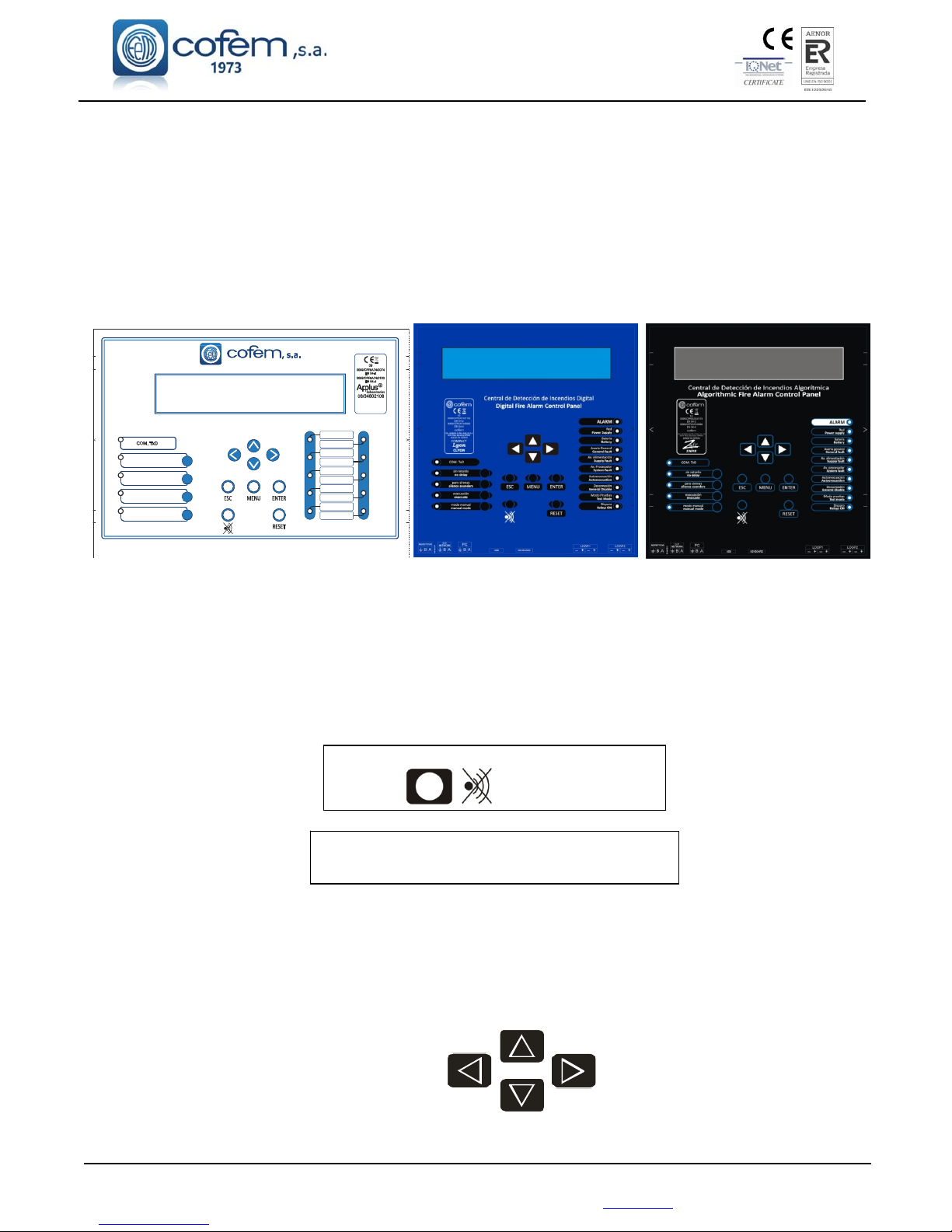
Digital fire detection control panel
LYON
FIRE PROTECTION MANUFACTURER
Ctra. de Molins de Rei a Rubí, Km. 8,4 - 08191 RUBÍ (Barcelona) ESPAÑA.
Tlf.: +34 935 862 690 - Fax:+34 936 999 261 - [email protected] - www.cofem.com 69
SINRETARDO
NODELAY
PAROSIRENAS
SILENCESOUNDERS
ALARMA
ALARM
DESCONEXIÓN
GENERALDISABLE
MODOPRUEBAS
TESTMODE
AVERÍAGENERAL
GENERALFAULT
ALIMENTACIÓN
POWERSUPPLY
AV.ALIMENTACIÓN
SUPPLYFAULT
AV.PROCESADOR
SYSTEMFAULT
DISPARO
RELAYSON
CentraldeDeteccióndeIncendiosInteligente
IntelligentFireAlarmControlPanel
V1-601020
EVACUACION
EVACUATE
MODOMANUAL
MANUALMODE
AUTOEVACUACIÓN
AUTOEVACUATION
BATERÍA
BATTERY
Ctra. de Molins de Rei a Rubí
km. 8,4 08191 Rubí
Barcelona (SPAIN)
MADE IN SPAIN
Annex 1: Use of the Control Panel LYON / C-LYON / ZAFIR system
1. What is a control panel LYON / C_LYON /ZAFIR SYSTEM?
The LYON / C_LYON / ZAFIR system is a FIRE detection system that combined with detectors and
corresponding modules, is capable of quickly detecting the early signs of a fire, issuing a warning of the event and
acting on various elements, such as emergency exit doors, acoustic fire alarms or crossed outputs.
2. Front panel of the system
This is what the control panel of the centralised LYON system looks like:
The keys enable action to be taken via the control unit, while the luminous indicators (LEDs) and the screen
provide information about the system status.
3. What happens if the buzzer sounds?
The buzzer or acoustic warning emits an intermittent alarm if any of the following situations arise:
1. A fire alarm has been generated.
2. A relay has been actuated.
3. A fault has occurred in the detection system.
To stop the buzzer, press this key:
IMPORTANT: THE INCIDENT must always be
CHECKED when this key is pressed.
4. Checking the incident
Having stopped the buzzer, the user must check the incident. For this purpose, the control unit incorporates a screen
to display information and various luminous indicators that provide details regarding the incident that has occurred.
The options are: an ALARM, an ACTUATION or a FAULT.
In the event of several types of incident occurring simultaneously, the display can be toggled by pressing the
ENTER key. The information displayed on the screen can be expanded using:
Page 70
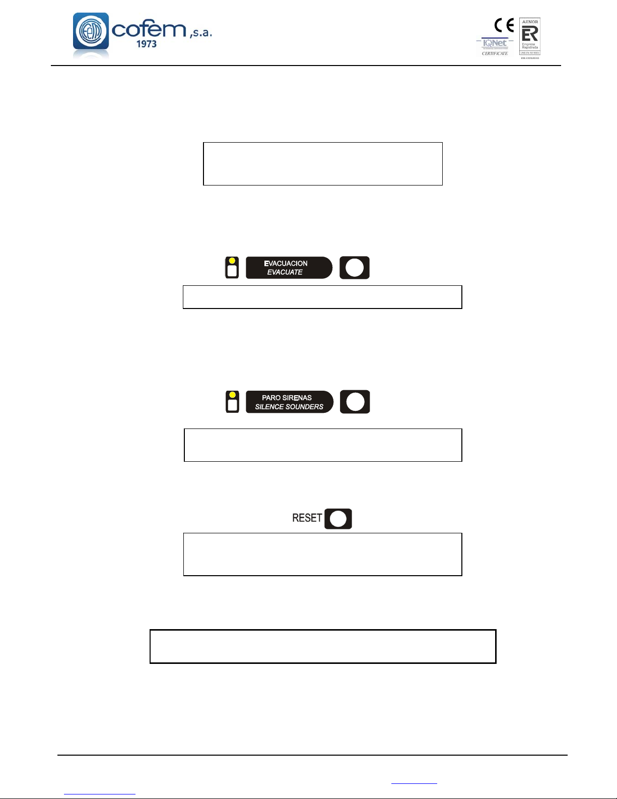
Digital fire detection control panel
LYON
FIRE PROTECTION MANUFACTURER
Ctra. de Molins de Rei a Rubí, Km. 8,4 - 08191 RUBÍ (Barcelona) ESPAÑA.
If the incident in question is an ALARM, the user must verify whether it is real. If so, the order to evacuate can be
given. Beforehand, the keypad must be enabled and also if any of the keys on the control panel are pressed,
except for the buzzer (the control panel requests a code to be entered):
To enable the keypad, the access code must be entered by using the (▲▼◄►) keys:
The access code is:
27
(This must be confirmed with the ENTER key).
This operation must be performed each time an access code is requested. Once the code has been entered, all the
keys on the control panel can be used.
5. Evacuation
This function can be performed once the keypad has been enabled and by pressing the evacuation key.
IMPORTANT: This must be confirmed with the ENTER key
This function activates all sirens and switches in the system. This is also shown by lighting the luminous indicator.
6. SILENCE SIRENS
When required, this function enables the sirens to be silenced. The keypad must be enabled and it is performed by
pressing the SILENCE SOUNDERS key:
IMPORTANT: while the luminous indicator is lit, the system’s
sirens will NEVER be activated.
7. RESET EVENTS
In the case of a false alarm, the user must Reset the alarm. With the keypad enabled, select the alarm to be reset
and press the reset key:
IMPORTANT: when an alarm is reset, this must be confirmed
with the ENTER key
If the incident is a FAULT, this must also be Reset following the exact same process as explained above. If the
FAULT reoccurs, contact the technical service.
DISCONNECT the 110~230V POWER supply and the BATTERIES before
accessing the interior of the control unit.
Page 71
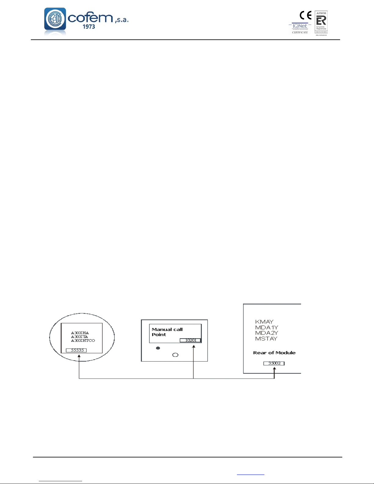
Digital fire detection control panel
LYON
FIRE PROTECTION MANUFACTURER
Ctra. de Molins de Rei a Rubí, Km. 8,4 - 08191 RUBÍ (Barcelona) ESPAÑA.
Tlf.: +34 935 862 690 - Fax:+34 936 999 261 - [email protected] - www.cofem.com 71
Annex 2: Elements configuration Lyon / C-Lyon / Zafir
1. Introduction
The steps necessary to configure the Analogue Control Panel LYON are given below.
The analogue system includes the following elements:
Analogue detectors
. Optical sensor A30XHA
Heat sensor A30XTA
Multi-sensor A30XHTCO
Analogue key PUCAY
Master module KMAY
Relay modules
1 relay MDA1Y
2 relays MDA2Y
Technical signals module MSTAY
Relay and Technical signal module MYOA
Loop isolator base KABY
Analogue siren SIRAY / SIRAYL
Each of these elements has a programming label. This number is assigned at the factory. When an element search
operation is conducted using the control unit, it finds all the loop elements, memorising the type of element and the
assigned programming number.
The basic purpose of this procedure is that, by conducting this search, all these numbers can be passed to the
control unit memory and for them to be assigned to the loop where the search was conducted.
NOTE: Before assigning a point, it is highly advisable to obtain the programming lists with all the data.
2. Keypad access
If the keypad has not been enabled, the only key that will work is the stop BUZZER button (in the event of any
new incidents, the buzzer will be activated again). The LYON / / C-LYON / ZAFIR system provides several
different access levels to the various internal functions. The first level of access controls the use of the keypad.
When any of the keys on the control panel are pressed, an access code will be requested:
Page 72
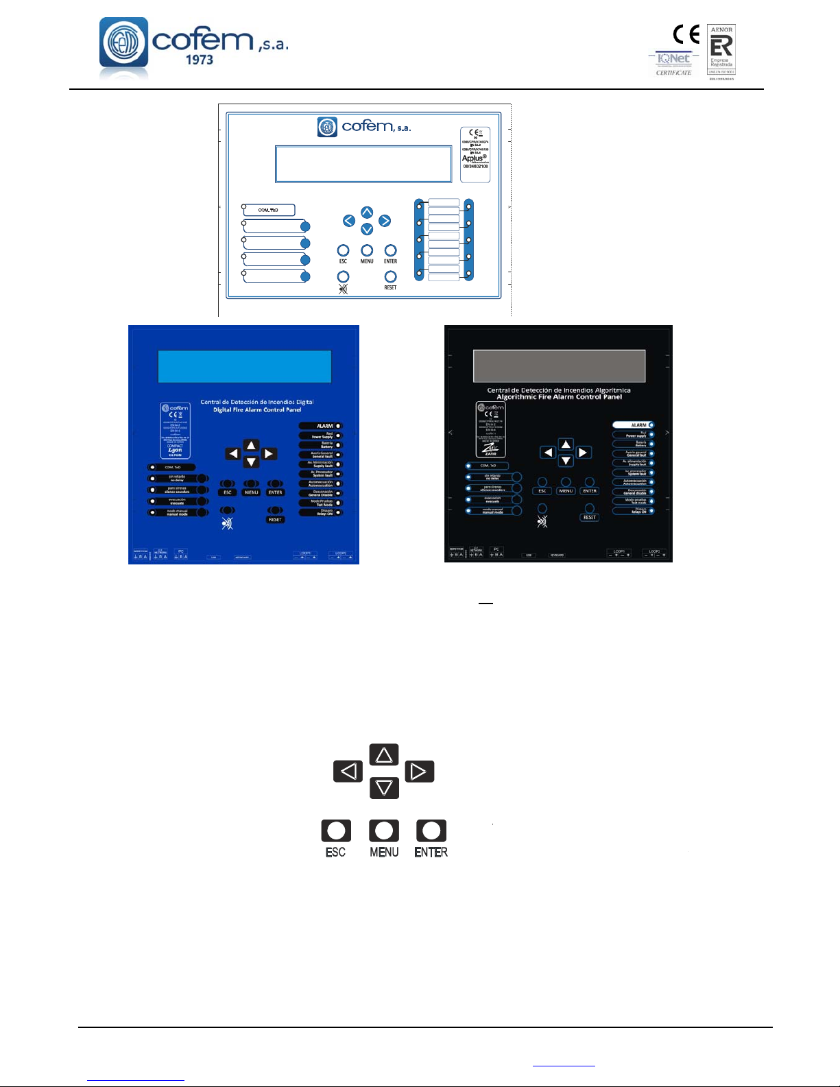
Digital fire detection control panel
LYON
FIRE PROTECTION MANUFACTURER
Ctra. de Molins de Rei a Rubí, Km. 8,4 - 08191 RUBÍ (Barcelona) ESPAÑA.
TECLAS PARA MOVERSE
POR LOS MENUS
TECLA ESCAPE
(vuelva a la pantalla anterior)
TECLA ENTER
(confirmar las opciones de menú
)
AN ACCESS CODE WILL BE REQUESTED Nº 27
IMPORTANT: If no key is pressed within a period of 30 seconds, the keypad is blocked and the previous step
must be repeated in order to continue using the keypad.
As soon as keypad access has been provided, all keys can be used immediately.
3. Configuration of points in a loop
Pressing the menu button will show the main menu on the display.
KEYS FOR NAVIGATING
THE MENUS
ESCAPE KEY ENTER KEY
(Return to previous screen) (Confirm menu options)
By using the arrow keys, the menu options below will be displayed:
1 Monitor
2 Logical relay activation
3 General relays
4 System configuration
5 Elements/zones in/out of service
6 System test
7 Welcome message
8 General reset
SINRETARDO
NODELAY
PAROSIRENAS
SILENCESOUNDERS
ALARMA
ALARM
DESCONEXIÓN
GENERALDISABLE
MODOPRUEBAS
TESTMODE
AVERÍAGENERAL
GENERALFAULT
ALIMENTACIÓN
POWERSUPPLY
AV.ALIMENTACIÓN
SUPPLYFAULT
AV.PROCESADOR
SYSTEMFAULT
DISPARO
RELAYSON
CentraldeDeteccióndeIncendiosInteligente
IntelligentFireAlarmControlPanel
V1-601020
EVACUACION
EVACUATE
MODOMANUAL
MANUALMODE
AUTOEVACUACIÓN
AUTOEVACUATION
BATERÍA
BATTERY
Ctra. de Molins de Rei a Rubí
km. 8,4 08191 Rubí
Barcelona (SPAIN)
MADE IN SPAIN
Page 73

Digital fire detection control panel
LYON
FIRE PROTECTION MANUFACTURER
Ctra. de Molins de Rei a Rubí, Km. 8,4 - 08191 RUBÍ (Barcelona) ESPAÑA.
Tlf.: +34 935 862 690 - Fax:+34 936 999 261 - [email protected] - www.cofem.com 73
3.1. System Programming
By selecting option 4 System Configuration, the access code for level 3 will be requested. Enter the code and
confirm with the ENTER key.
AN ACCESS CODE WILL BE REQUESTED Nº 9000
The following menu will appear on the display:
1 Review history
2 Label elements
3 Configure
4 Update date and time
5 Day/Night times
6 Activate test/normal mode
7 Language menu
8 Communications
3.2. Configure
Select option 3 Configure, and confirm with the ENTER key.
The following menu with 6 options will appear on the display:
1 Loop Configuration
2 Configure Logical Relays
3 Configure Alarm Zones
4 Configure Element Sensitivity
5 Additional Passwords
6 Configure Auto Evacuation
3.3. Configure Loop
By selecting option 1 Loop Configuration the option will be the first to appear. Confirm with the ENTER
key. You will be asked for the number of the loop to be configured.
The following menu with 3 options will appear on the display:
1 Sensitivity of a type
2 Flashing
3 Point configuration
3.4. Loop Configuration
The first step is to configure the elements of the loop so that the control unit recognises all the Elements that
are connected to each of the loops.
By selecting option 3 Point Configuration the option will be the first to appear. Confirm with the ENTER key.
The following menu with 7 options will appear on the display:
1 View loop information
2 Search for loop element
3 Assign a number to an element
4 Automatic loop configuration
5 Delete point
6 Delete programming number
7 Delete loop element
By selecting option 2 Search for loop element the option will be the first to appear. Confirm with the ENTER key.
This function passes all the programming numbers to the control unit memory and, after a few seconds, the total
number of elements that have been configured in the loop will appear on the display and how many there are of
each type. This search will take approximately 80 seconds.
Check that the information displayed is correct.
Important note:
This step must be performed for each of the installed loops. It must be done even if there are no elements connected
to the loop.
Page 74
Digital fire detection control panel
LYON
FIRE PROTECTION MANUFACTURER
Ctra. de Molins de Rei a Rubí, Km. 8,4 - 08191 RUBÍ (Barcelona) ESPAÑA.
0 1 > Z : 0 0 1 L AB E L 0 1 0 1 0 0 6
A L A R M S C : B : P t :
< < 0 1 / 0 2
3.5. Assign a number to Point
By selecting option 4 assign a number to an element the option will be the first to appear. Confirm with the
ENTER key.
This option assigns a loop and an order number within the loop to each element.
Important:
In order to proceed with this operation, the installer must have made written note of the programming number of
each of the detectors and the loop in which they are installed.
Firstly, you will be asked for the programming number of the corresponding Point, confirmed with the ENTER
key. Secondly, you will be asked for the assigned Point number, confirmed with the ENTER key.
4. Programming verification process
It is always recommended to check that programming has been performed correctly.
Monitor
This function is number 1 on the first menu. Select with the ENTER key.
Firstly, you will be asked for the number of the loop and then the programming number of the element.
Check that the information shown is correct.
With the ( ) arrow keys, it is possible to change from one point to another.
With the ( ) arrow keys, it is possible to change from one loop to another
5. Configure Zones
The purpose of an alarm zone is to provide more complete information and to achieve greater speed when locating
an element with an alarm. The aim of a zone is to group together detectors that are located in the same area.
When an incident is detected by the control unit, pressing the () key will display the label of the zone to which
point belongs.
In order to configure alarm zones, it is necessary to follow the following steps:
Menu (access code 27) 4. System configuration (access code 9000) 3 Configure 3 Configure Alarm
Zones.
You will be asked for the number of the zone to configure. Enter the number and the following menu will appear:
1 Configure zone
2 Modify Lists
3 Delete zone
4 Label
5 View configuration
B : 1 P : 7 N S : 5 5 4 6 3 T Y P E : A 3 0 X T A
L O O P : 0 0 1 A D R E S S : 0 0 1 S. N u m. : 5 5 4 6 3
D i r t : 0 0 0 % A v e r a g e : - - - S e n s i t i v : M E D
V a l u e s : [ 0 2 2 0 2 2 ] L a s t : 0 0 00 2 2 0 2 2
Alarm zone
label
Page 75
Digital fire detection control panel
LYON
FIRE PROTECTION MANUFACTURER
Ctra. de Molins de Rei a Rubí, Km. 8,4 - 08191 RUBÍ (Barcelona) ESPAÑA.
Tlf.: +34 935 862 690 - Fax:+34 936 999 261 - [email protected] - www.cofem.com 75
By selecting option 1 Configure Zone the option will be the first to appear. Confirm with the ENTER key.
Important: 8 possible lists are available for each zone. Firstly, you will be asked for the loop and number of the
first point. Secondly, you will be asked for the last point number for the list. Always confirm with the ENTER key.
Once configuration of the zone is complete, it is important to view the zone configuration using option 5 in order to
check it has been configured correctly.
In order to give a name to a zone, you must select option 4 Label, confirming with the ENTER key. Within this
option, select the character (letter or number) using the up and down arrow keys and change position in the label
using the left and right cursors arrow keys. Save the label using the ENTER key.
6. Replacing a loop element
1 The first step is to know exactly which element is to be replaced.
Number of the LOOP in which it is installed
Number of the point within the loop
PROGRAMMING number of the loop element
2 Make note of the loop configuration.
See chapter: 3.4 Loop Configuration. It is option 1 on the element configuration menu.
3 Delete the point removed from the loop.
See chapter: 3.4 Loop Configuration. It is option 5 of the element configuration menu.
4 Insert the new element (having previously made note of the programming number).
5 Search loop element. When this has been completed, the configuration will be shown on the display. Check that
the configuration is the same as in step 2 above, but with the new element added.
See chapter: 3.4 Loop Configuration. It is option 2 of the point configuration menu.
6 Assign number to element.
See chapter: 3.5 Assign a number to a point. It is option 3 of the point configuration menu.
7 Whenever a modification is made, the changes should always be checked.
See chapter: Monitor. It is option 1 of the main menu.
DISCONNECT the 110~230V POWER supply and the BATTERIES before
accessing the interior of the control unit.
NOTE:
COFEM S.A. reserves the right to make changes due to typographical errors, inaccuracies in the current information or program and/or equipment
improvements at any time and without prior notice.
L O O P : 0 1 A 3 0 X T A : 0 0 0 M D A x Y : 0 0 0
A 3 0 X H A / S : 0 0 4 S I R A Y : 0 0 0
P O I N T S : 0 0 5 A 3 0 X H T C O : 0 0 0 M S T A Y : 0 0 0
P U C A Y : 0 0 1 K M A Y : 0 0 0
Page 76

FABRICANTE DE PRODUCTOS CONTRA INCENDIOS - FIRE PROTECTION MANUFACTURER
FABRICANTS DE PRODUITS CONTRE INCENDIES
Ctra. de Molins de Rei a Rubí, Km. 8,4 - 08191 RUBÍ (Barcelona) SPAIN
Comercial
Commercial
Ventas
Sales
Atención Técnico Comercial
Technical & Commercial Service
& C S
S.A.T.
T.A.S
Compras
Purchase
Export
Export
Fax
pedidos
Fax pedidos
Orders Fax
Fax general
Fax
+34 935 862 690
+34 935 862 690
+34 902 448 811
+34 935 862 692
+34 935 862 693
+34 935 862 694
34 902 338 811
+34 902 338 811
+34 936 999 261
 Loading...