

Page 1

manual system
12 plus
manuale
di istruzioni
intructions
manual
1^ edizione, luglio 1998
1st edition, july 1998
Page 2

Index
1. General characteristics
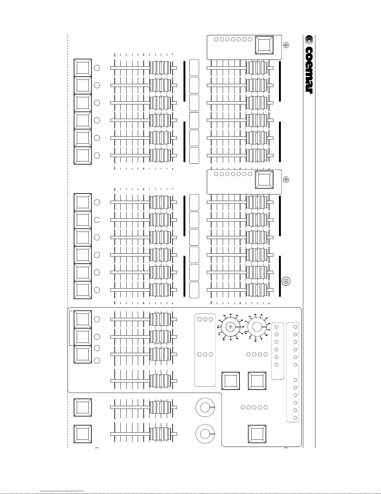
2. Controller elements and functions
3. DMX 512 signal connection
4. DMX address setting
(installer option only)
4.1. addressing via dip-switches
4.2. addressing via a digital display
5. Power supply
6. Powering up
7. Connecting audio input and adjusting sensitivity
7.1 Adjusting input sensitivity
8. Manual operation
8.1. Adjusting output levels
8.2. Timed A/B crossfades
8.3. Flash buttons
9. Using pre-programmed effects
9.1. Single zone effects generator
9.2. Multi zone effects generator
9.3. Outputting an effect
9.4. Effects generator advanced functions
10. DMX patch
10.1. Viewing DMX channel assignments (patch)
10.2. Altering DMX channel assignments (patch)
11.Controlling the strobe effect of a motorised projetor
11.1. Zone 1 (sliders 1 to 6)
11.2. Zone 2 (sliders 7 to 12)
12.Controlling colour selection in a motorised projector
13.Manual system 12 plus as a controller for:
13.1. tas colore a.t.
13.2. tas colore fresnel and VersìColore
13.3. tas VersìColore
14.Dip-Switches
15.Technical characteristics
Authorised sevice centres worldwide
Page 3

1. General characteristics
Manual controls:
• ON/OFF switch at rear
•2 presets with 12 channels on each
• 12 channel flash buttons
•2 master preset sliders
• A and B flash masters
• variable time delay on the master preset
• crossfade ability
• individual channel output level leds
• individual channel preview leds
• flash buttons can be inhibited
• 72 channels of DMX patching
• patch states can be locked
• indicators for: • power on
• DMX 512 output
• correct audio input level
• patch activated
• channels can be set to swtich only for motorised or strobe effects
• flash buttons disenabled
Effects generated:
•1 master effects slider
• 2 buttons for manual advancing of sequential/chase effects
• Four 4 channel chase effects (single zone)
• Eight 6 channel chase effects (single zone)
• Twelve 12 channel chase effects (multi zone)
• variable program step speeds
• chases can be stepped in sound-to-light mode, manually, at variable speed or crossfaded
• super auto function for completely automated light shows in the absence of an operator
• output monitoring
tas Colore dedicated effects:
• sound-to-light selection mode or random selection mode for colours
• 2 sliders assignable to a single DMX channel, particularly useful for control over frost, and colour selection
•1 master slider for strobe effect
Page 4
flash flash color-1+1
random music
trigger
full
manual
crossfade
audio
7 8 9 10 11 12
output
123456
100
0
102030405060708090
100
0
102030405060708090
123456 789101112
10 20 30 40 50 60
100
0
10203040506070
80
90
100
0
102030405060708090
100
0
1020304050
60
708090
crossfade
full
super auto
standby
audio
manual
direct
mode/
transfer
crossfade
full
super auto
standby
audio
manual
direct
mode/
transfer
100
0
1020304050
60
708090
100
0
102030405060708090
output
123456 789101112
flash master
100
0
102030405060708090
18
70
90
108
126
144
162
180
200
0
54
18
36
70
90
108
126
144
162
180
200
0
54
36
delay time(sec.)
master Bmaster A
manual system
12 plus
DMX 512
effects
generator
frost strobe color
mode
transfer
selector
clear all
super auto
multi zone
preview
preview
dmx patch
effects
DMX 512 out
audio in
+20 V DC
flash inhibit
DMX patch
strobe setting
single zone
speed
preset A
preset B
preset A
preset B
Page 5
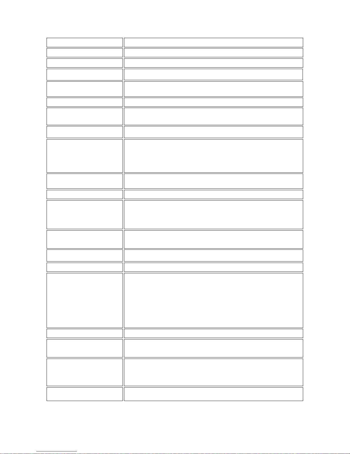
2. Control panel functions
Useful sliders for assigning of particular channels, such as motorised projectors, particularly useful for the control of frost filters and colourchange channels.
frost and color sliders
Generates an automatic change in the output level of the channels assigned via the
DMX patch function to the color slider.
The effect can be in a random mode or in sound-to-light (music) mode
Also allows in patch mode the assigning of any channel to the color slider, activation is indicated by the switching on of the led.
color button
Steps through the effect generated in manual mode, also allow, in patch mode,
the assigning of channels to the frost and strobo sliders, their activation is indicated by the switching on of their respective leds.
+1 -1 buttons
Display the assignments of the dmx channels in the DMX patch function.
DMX patch leds
Combined with the transfer button, it activates the programs created by the
effects generator; the two buttons must be pressed simultaneously
It also allows the manner in which the effect steps to be altered
full: 2 states, on and off
crossfade: fade out/in effect
audio: sound-to-light, able to be used with full and crossfade.
manual: manual, able to be used with full and crossfade, activated by +1 or -1.
direct: direct transfer from the effects generator
standby: halts the current effect being transferred until mode/transfer is pressed
again.
mode/transfer button
A general master over the effects generated and output.
effects slider
In combination the mode/transfer buttons activates the programs created by the
effects generator; the two buttons must be pressed simultaneously
transfer button
Monitors the effects generated, allows preview monitoring prior to live action.
Displays the channel assignments created in DMX patch.
preview leds
Selects the various operating modes for selected programs
full: 2 states, on and off
crossfade: fade out/in effect
audio: sound-to-light, able to be used with full and crossfade.
manual: manual, able to be used with full and crossfade, activated by +1 or -1.
trigger button
Adjusts the step speed in programs
speed potentiometer
Allows the selection of 4, 6 or 12 channel programs
rotating selector
switch
Sets various parameter functions in effects generator:
single zone: the effects generator (selector) indicates 4 or 6 channel chases
multi zone: the effects generator (selector) indicates 12 channel chases
super auto: the effects generator indicates programs being run automatically
preview: displays via the preview leds the output states
clear all: interupts all program creation or outputs
mode button
Monitor channel output levels and also dmx channel assignments in the DMX
patch function.
output leds
Allows all 12 channels to be flashed to the maximum level determined by presets A
and B, overriding the levels set by the master A and B sliders. Also allows the
checking of individual channels in the DMX patch function.
flash master buttons
Allows individual channels to be flashed at full, irrespective of any preset level.
flash button
Allows an automatic time delay to be assigned to the master preset; even in crossfades
delay time
potentiometer
Controls the overall output level dictated by the preset A and preset B sliders
master A/B slider
Controls the overall output level on each channel in preset B
preset B slider
Controls the overall output level on each channel in preset A.
preset A slider
Powers up the manual system 12 plus.
power button
Page 6

DMX 512 out: indicates that DMX 512 is being ouput
audio in: audio input signal monitor
+ 20 V DC: indicates power supply presence
flash inhibit: flash buttons are disenabled
DMX patch: patch is activated
strobe setting: motorised fitting’s strobe channel facility is activated
function leds
Useful sliders for assigning of particular channels, such as motorised projectors, particularly useful for the control of strobes. The slider is automatically assigned when the
dip-switches strobo 1/6 and 7/12 are set. It will trigger the strobe effect on these
particular effects.
TECHNICAL NOTE: the strobing function is active in the range 150 to 245 on any
dimmer channel, which will operate normally in the range 0 to 125.
strobe slider
Page 7
3. DMX 512 signal connection
manual system 12 plus outputs via an XLR 5, 72 channels of DMX 512; varying the output via the sliders and com-
mand buttons from 0 to 255, according to the international standards for digital distribution of DMX 512, as regulated by
the USITT (U.S Intitute of Theatre Technology)
All equipment which accepts this digital control signal is controllable via the manual system 12 plus.
Connection between the manual system 12 plus and any DMX 512 conforms to this standard:
Output via the XLR5 outlet on the manual system 12 plus:
Pin 1= Ground (GND)
Pin 2= DATA Pin 3= DATA +
Pin 4= Optional Pin 5= Optional +
If cabling and connection components are required, they can be manufactured from the following coemar components:
ME 1344 (XLR 3 plug)
ME 1230 (XLR 3 socket)
ME 4966 (XLR 5 plug)
ME 4965 (XLR 5 socket)
CV 4158 (2 core, screened Ø 0,5 cable, per metre)
Connection should be via 2 core screened cable which meets the above mentioned standards.
Screening should always be connected to pin 1 of the XLR and should be totally insulated from the metal housing, polarity
should be maintained.
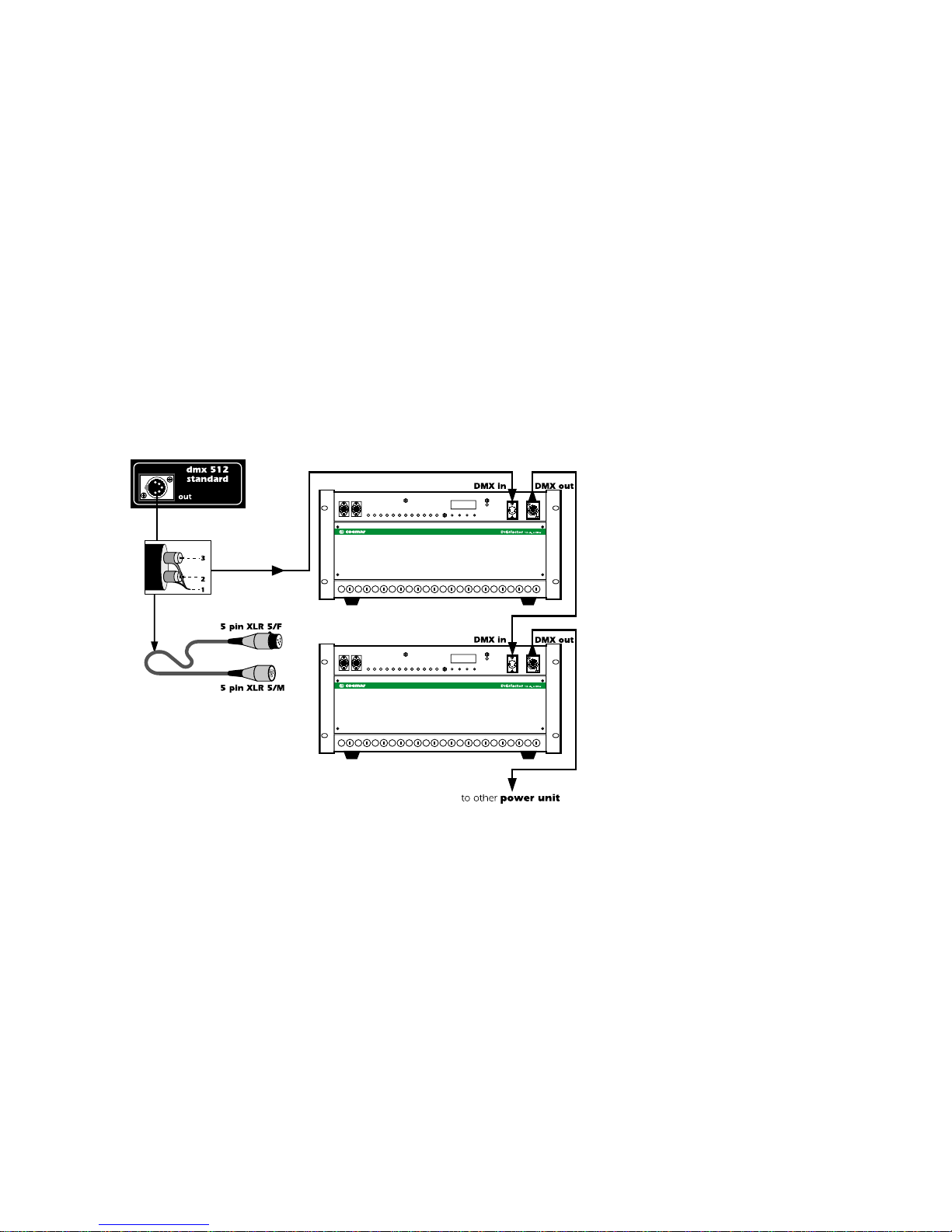
An example of DMX 512 connection:
If the equipment receiving the DMX 512 signal from the manual system 12 plus uses an XLR 3 connector, simply leave
pins 4 and 5 unconnected, this being internationally acceptable in a DMX 512 control system.
All DMX 512 controlled equipment, whether dimmers or motorised projectors, require the correct DMX address to be set
on them in order to operate via the manual system 12 plus.
Consult your respective equipment’s manuals for instructions in setting DMX 512 addresses.
Page 8
4. DMX address setting (installer option only)
The manual system 12 plus outputs only DMX digital control signal.
manual system 12 plus outputs 72 channels of DMX 512, assignable to the controllers on the front panel via the
DMX patch.
The controller is normally sold in a standard configuration whereby DMX channels from 1 to 12 are controlled from sliders
1 to 12, any alteration to this setting will result in the DMX patch led being set to on.
This assigning of channels 1 through 12 is repeated identically for channels 13 to 72. If you wish to alter the setting, you
will need to utilise the DMX 512 patch function, which is explained in detail in section 10 of this manual.
Prior to being operated, the unit being controlled will need to be set to the address DMX 1 to respond correctly to the first
12 channels being output by the manual system 12 plus.
Depending upon the number of channels being used by this first device, subsequent DMX addresses should be set in multiples of 3, 468or 12.
The following two examples will provide an indication of how the user may set the address for particular fixtures using
either a digital display or dip-switches.
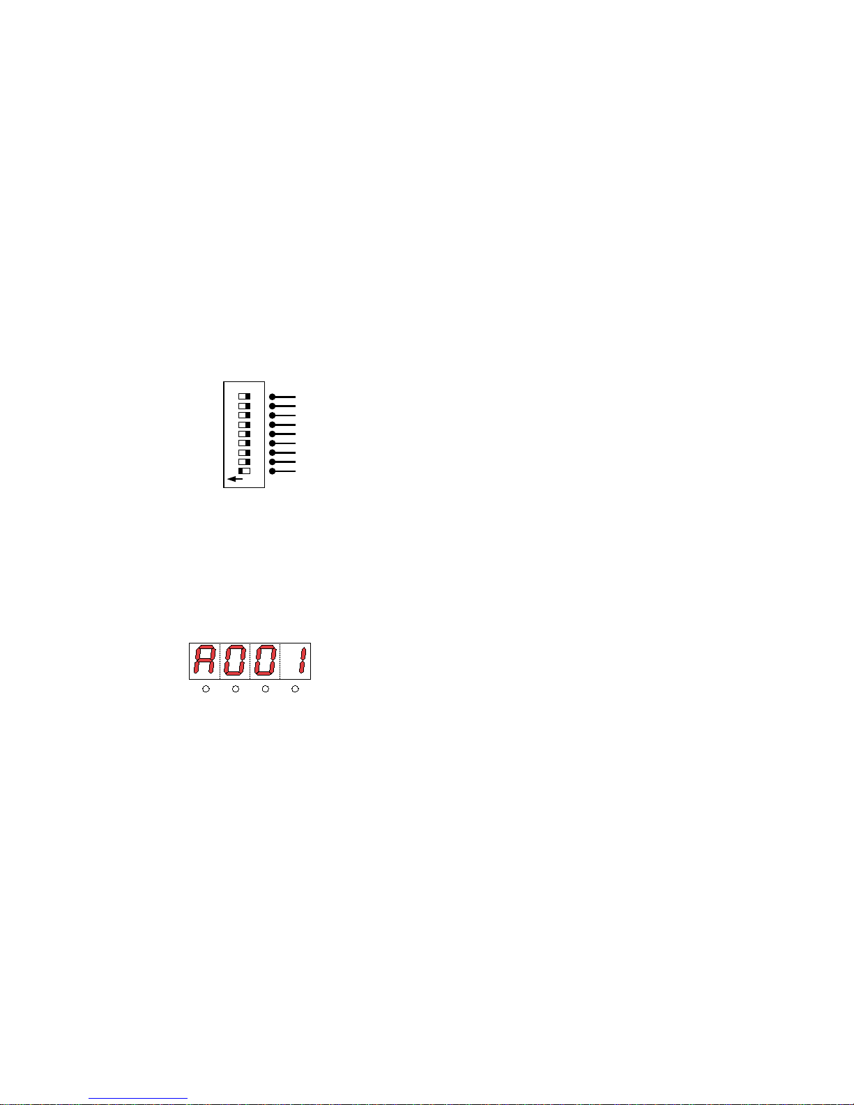
4.1. Addressing via dip-switches
Respective dip-switches have a unique numerical value, you will need to set to ON only the switch which has the value 1
(for address DMX 1) to ensure correct communication between fixture and the first channel of DMX 512.
Depending upon the number of DMX channels required, subsequent settings should be multiples of 3, 4, 6, 8, or 12.
The following diagram shows that only dip-switch number 1 should be switched to on.
Multiple dimmer racks or fixtures can be controlled in parallel, for further information, refer to the unit’s respective manuals.
4.2. Addressing via a digital display
The first fixture should be addressed as DMX number 1.
Depending upon the number of DMX channels required, subsequent settings should be multiples of 3, 4, 6, 8, or 12.
The following diagram shows a connection between a manual system 12 plus controlled and a coemar DIGIfactor
12 ch dimmer rack.
Multiple dimmer racks or fixtures can be controlled in parallel, for further information, refer to the unit’s respective manuals.
After connection to the DIGIfactor 12 ch:
1- Press the + or - buttons until the display shows DMX A001, the display panel characters will flash to indicate the
address has not been recorded.
2- Press the enter button to confirm your selection; the display panel characters will cease flashing and the dimmer will
now respond to DMX channel 1.
function display
menu
+-
enter
dip-switch
256
128
64
32
16
8
4
2
1
on
Page 9
5. Power supply
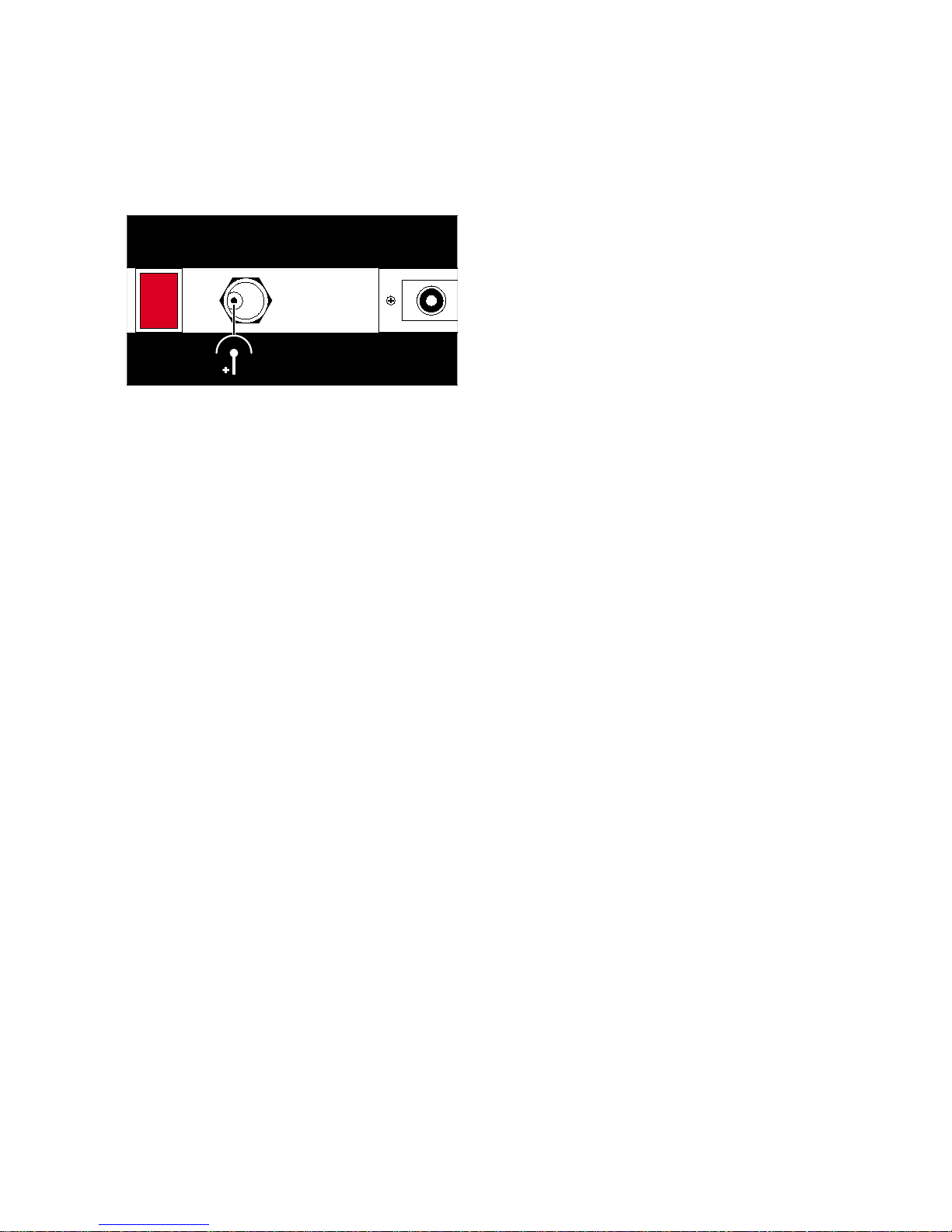
To power up the manual system 12 plus connect a +20V DC power supply to the socket at the rear of the controller
(minimum amperage 400 mA.)
The power supply’s plug should be compatible with the socket at the rear of the manual system 12 plus:
Power supply plug dimensions: Ø internal 2,1mm, Ø external 5,5mm.
When connecting to a 230V 50/60 Hz outlet, we recommend the use of a coemar power supply, available from our distributors as item code:
FO644/2 (for mains power 230V 50/60Hz)
Power supply
requirements:
Tensione di
alimentazione:
+20v DC only,
400 mA min.
power
ON
+20V DC
Page 10

6. Powering up
After having connected the correct power supply to the manual system 12 plus, as described in section 5, power the
controller up by switching the power button at the rear of the unit to the ON position.
The +20 V DC led will come on to indicate that the manual system 12 plus has been powered up correctly.
DMX 512 out
audio in
+20 V DC
flash inhibit
DMX patch
strobe setting
Page 11
7. Connecting audio input and adjusting sensitivity
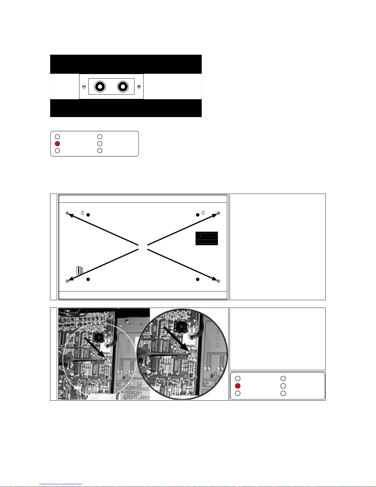
Connecting audio input allows programs to be run in sound-to-light mode; signal can be connected via the 2 RCA stereo
sockets (100mV at 10V RMS), located on the rear of the manual system 12 plus
Audio input can be from any mixer with variable output from 100mV up to 10V RMS maximum. Correct levels of audio
input can be monitored via the audio in led which will flash to the bass rhythm.
The audio input circuitry is auto adjusting; however it is possible to adjust the input level to ensure the manual system 12
plus is able to accomodate audio input from souces where the input levels are less than perfect.
7.1 Adjusting input sensitivity
The following procedure should only be undertaken if absolutely necessary.
Input sensitivity can be adjusted via the following procedure:
Power up the manual system 12 plus and ensure that audio input is connected via the RCA. plugs on the rear panel.
Re-position and secure the rear panel.
DMX 512 out
audio in
+20 V DC
flash inhibit
DMX patch
strobe setting
Locate the trimmer/adjuster (B) and,
using a plastic electronics screwdriver,
adjust the trimmer so that the audio IN
led (on the front of the controller) flashes
on and off in perfect timing with the bass
signal being generated.
2-
Use a screwdriver to remove the four
screws (A) which attach the rear panel of
the manual system 12 plus.
dip-switch
optional
optional
optional
optional
flash inhibit
patch lock
strobo 7/12
strobo 1/6
manual system 12 plus
DMX 512
inspected by
A
1-
DMX 512 out
audio in
+20 V DC
flash inhibit
DMX patch
strobe setting
Audio In
100mV / 10V RMS
pply
ents:
di
zione:
only,
min.
Page 12
8.Manual operation
This section refers to adjusting ourput levels; the result of adjusting output will vary according to the fixture being controlled
and the channel settings; for ease of explanation, all instructions in this section are made with the understanding that the
DMX patch facility is not in use. Details on this facility can be found in section 10.
Check that the DMX 512 out led is flashing to ensure that the manual system 12 plus is outputting signal and that
the + 20 V DC led is on, indicating that power is being supplied to the controller.
If the + 20 V DC led is off, check the system as described in sections 5 and 6 of this manual.
8.1. Adjusting output levels
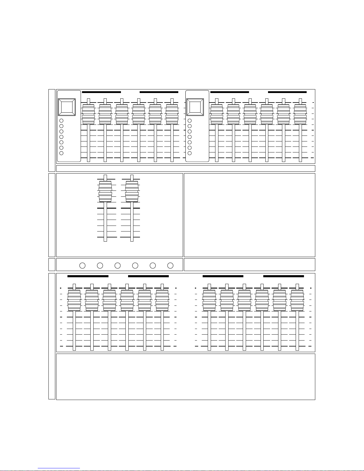
This procedure allows all 12 channels to be adjusted to respective levels of output signal.
A different set of output levels can be set on the B preset sliders; when you wish to view these outputs, lower the
master A slider and raise the master B slider; this will crossfade between the A presets and the B presets.
Setting the master A and B sliders both to a similar level above 0 will result in the higher of the two levels on the
individual channels being output.
For example, if channel 1 on preset A is set to 50% and the same channel 1 is also at 50% on preset B, then channel 1 will output at 50%.
However, if channel 1 on preset A is set to 50% and the same channel 1 is at 70% on preset B, channel 1 will
ouput at 70%; the highest level taking precedence.
100
0
10
20
30
40
50
60
70
80
90
100
0
10
20
30
40
50
60
70
80
90
100
0
10
20
30
40
50
60
70
80
90
100
0
10
20
30
40
50
60
70
80
90
preset B preset B
4-
The green output leds will mimic the output levels of
their respective channels as set.
output
123456
3-
Adjust the master A slider to view the output levelsof each
channel.
100
0
10
20
30
40
50
60
70
80
90
master Bmaster A
2-
Adjust the levels of the 12 preset A sliders as desired.
crossfade
full
super auto
standby
audio
manual
direct
mode/
transfer
crossfade
full
super auto
standby
audio
manual
direct
mode/
transfer
100
0
10
20
30
40
50
60
70
80
90
100
0
10
20
30
40
50
60
70
80
90
preset A preset A
1-
Page 13
8.2. Timed A/B crossfades
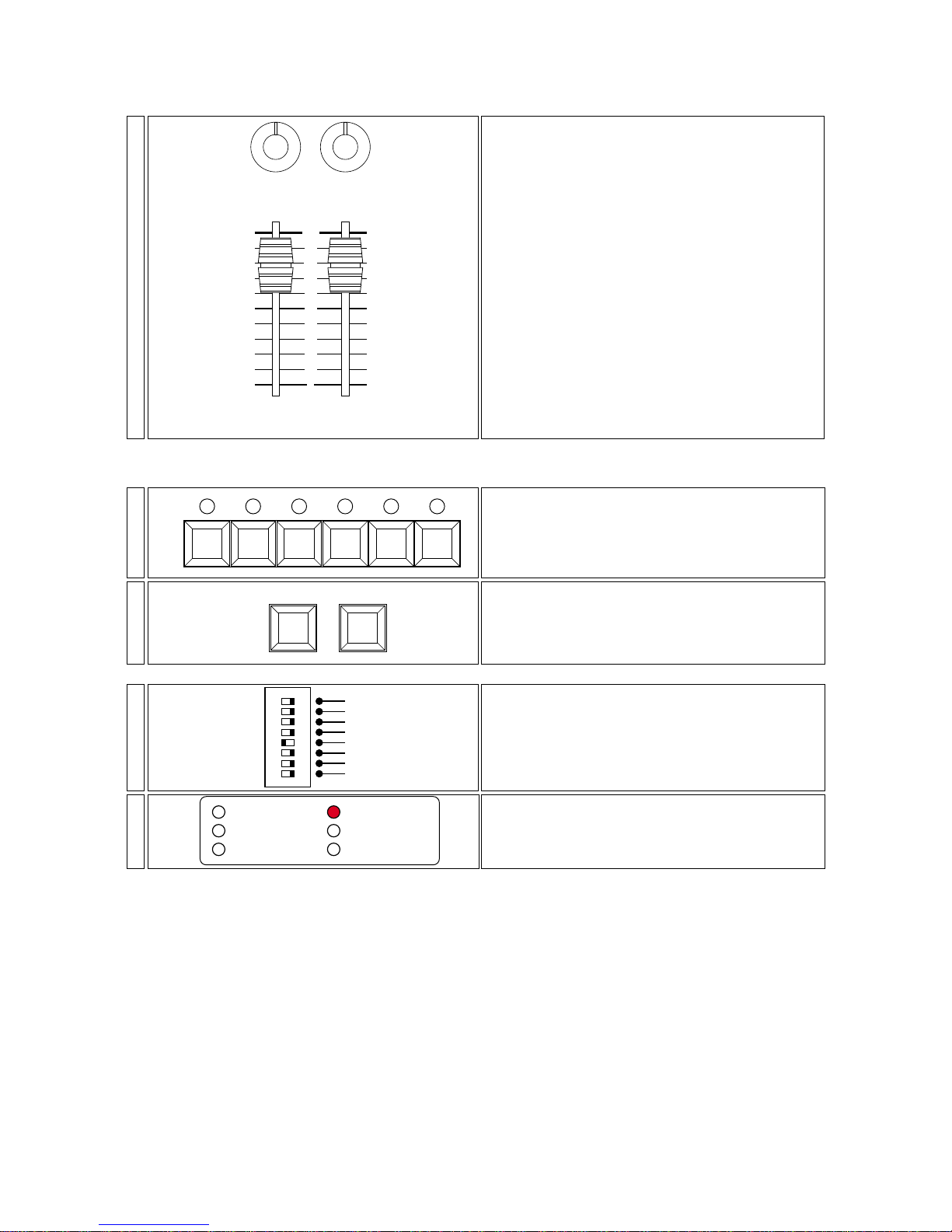
Using this function allows delays to be effected via the master sliders
8.3. Flash buttons
This function allows outputs to be instantly flashed up to maximum.
The flash buttons can be disenabled to avoid accidental use.
After setting the dip-switch as described above, the flash buttons will no longer function; repeat the operation setting the
flash inhibit to the OFF position if you wish to enable the flash buttons once again.
The flash inhibit led in the effects generator section
of the controller will come on to indicate the flash function
is disenabled.
DMX 512 out
audio in
+20 V DC
flash inhibit
DMX patch
strobe setting
4-
Locate at the rear of the manual system 12 plus the
dip-switches. The flash inhibit dip-switch function can be
activated by setting the dip-switch to ON.
dip-switch
optional
optional
optional
optional
flash inhibit
patch lock
strobo 7/12
strobo 1/6
ON
3-
flash master, there are two, one for each A/B preset.
Pressing either of these will flash the channels to the levels
determined by the individual channel sliders.
These act instantly, and over-ride the individual master sli-
ders.
flash master
master Bmaster A
2-
The flash buttons are always active, and will cause the
respective channels to flash at 100%
flash
output
123456
1-
To add a time delay to a master A or B, adjust the delay
time potentiometers
A timed crossfade between two presets can include a
black-out during the crossfade only if the first scene is
manually faded out, otherwise the crossfade will be governed by the times set on the potentionmeters.
Note 1: the time delay function operates both in fade up
and fade down actions.
Note 2: the time delay function operates over all channels
in the individual presets since the potentiometers act on
both masters A and B.
100
0
10
20
30
40
50
60
70
80
90
18
70
90
108
126
144
162
180
200
0
54
18
36
70
90
108
126
144
162
180
200
0
54
36
delay time(sec.)
master Bmaster A
1-
Page 14
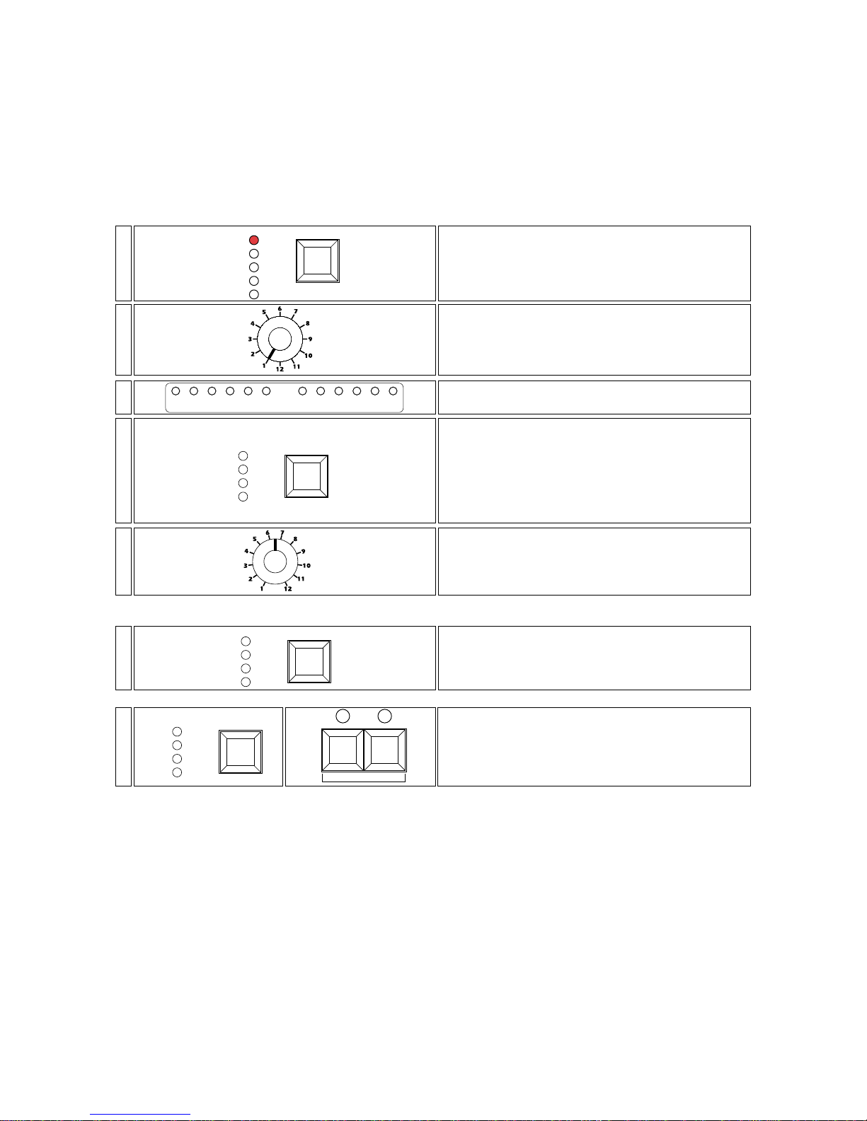
9. Using pre-pr ogrammed effects
manual system 12 plus provides several pre-programmed chase effects which can be used as required.
The programs can be single zone, for groups of six channels, or multi-zone utilising all 12 channels.
Note that these effects can take precedence over the manual operation described in previous sections.
9.1. Single zone effects generator
In single zone mode, there are 8 pre-programmed 6 channel chases (programs 1 to’ 8) and 4 pre-programmed 4 channel chases (programs 9 to 12).
The 4 channel chases allow the remaining 2 channels to be used as dimmer channels, independent of the effects generated; a typical usage of this may be to use the two remaining channels to control house lighting dimming, whilst a sound-tolight chase is occuring on the other channels
An alternative to assigning a chase speed via the speed potentiometer is to assign select either a sound-to-light option or a
manual step contolled by the operator.
or
To output the selected program, see section 9.3 of this manual.
Press the trigger button until the manual led is lit at the
same time as either full or crossfade.
In this mode the chase step advancement is controlled by
the operator; they may step through the chase forward or
back by using the +1 or -1 buttons.
-1+1
trigger
full
manual
crossfade
audio
7-
Press the trigger button until the audio led is lit at the
same time as either full or crossfade.
In this mode, chase step advancement is now contrtolled
via sound-to-light (see section 7).
trigger
full
manual
crossfade
audio
6-
You may alter the chase speed by using the speed potentiometer.
The preview leds will mimic the chase speed as it is altered
to facilitate selection.
speed
5-
Press the trigger when the required program is selected to
select the attack mode in which the chase will occur:
Channels can chase in one of two modes, either flash on/off
(full), or in a crossfade (crossfade); select the mode you
wish to utilise by pressing the trigger button until either of
the two leds full or crossfade are lit.
trigger
full
manual
crossfade
audio
4-
The preview leds 1 to 6 or 1 to 4 will mimic the program
selected.
preview
123456 789101112
3-
Select the required program 1 to 12 you wish to utilise via
the selector button.
selector
2-
Press and hold the mode button in the effects genera-
tor until the single zone led comes on.
mode
clear all
super auto
multi zone
preview
single zone
1-
Page 15
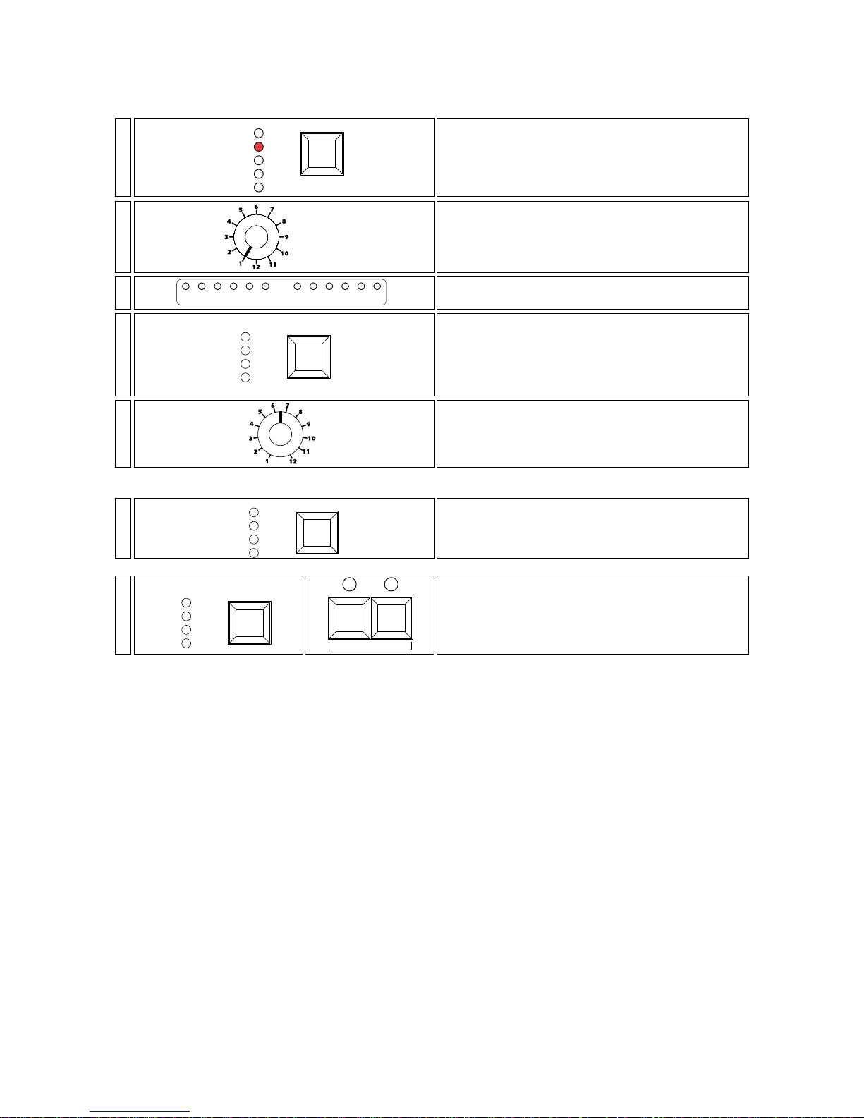
9.2. Multi zone effects generator
Multi zone effects are defined as those using all 12 channels of the manual system 12 plus. You may select from 12 different multi zone programs
An alternative to assigning a chase speed via the speed potentiometer is to assign select either a sound-to-light option or a
manual step contolled by the operator.
or
To output the selected program, see section 9.3 of this manual.
Press the trigger button until the manual led is lit at the
same time as either full or crossfade.
In this mode the chase step advancement is controlled by
the operator; they may step through the chase forward or
back by using the +1 or -1 buttons.
-1+1
trigger
full
manual
crossfade
audio
7-
Press the trigger button until the audio led is lit at the
same time as either full or crossfade.
In this mode, chase step advancement is now contrtolled
via sound-to-light (see section 7).
trigger
full
manual
crossfade
audio
6-
You may alter the chase speed by using the speed potentiometer.
The preview leds will mimic the chase speed as it is altered
to facilitate selection.
speed
5-
Press the trigger when the required program is selected to
select the attack mode in which the chase will occur:
Channels can chase in one of two modes, either flash on/off
(full), or in a crossfade (crossfade); select the mode you
wish to utilise by pressing the trigger button until either of
the two leds full or crossfade are lit.
trigger
full
manual
crossfade
audio
4-
The preview leds 1 to 12 will mimic the program selected.
preview
123456 789101112
3-
Select the required program 1 to 12 you wish to utilise via
the selector button.
selector
2-
Press and hold the mode button in the effects genera-
tor until the multi zone led comes on.
mode
clear all
super auto
multi zone
preview
single zone
1-
Page 16
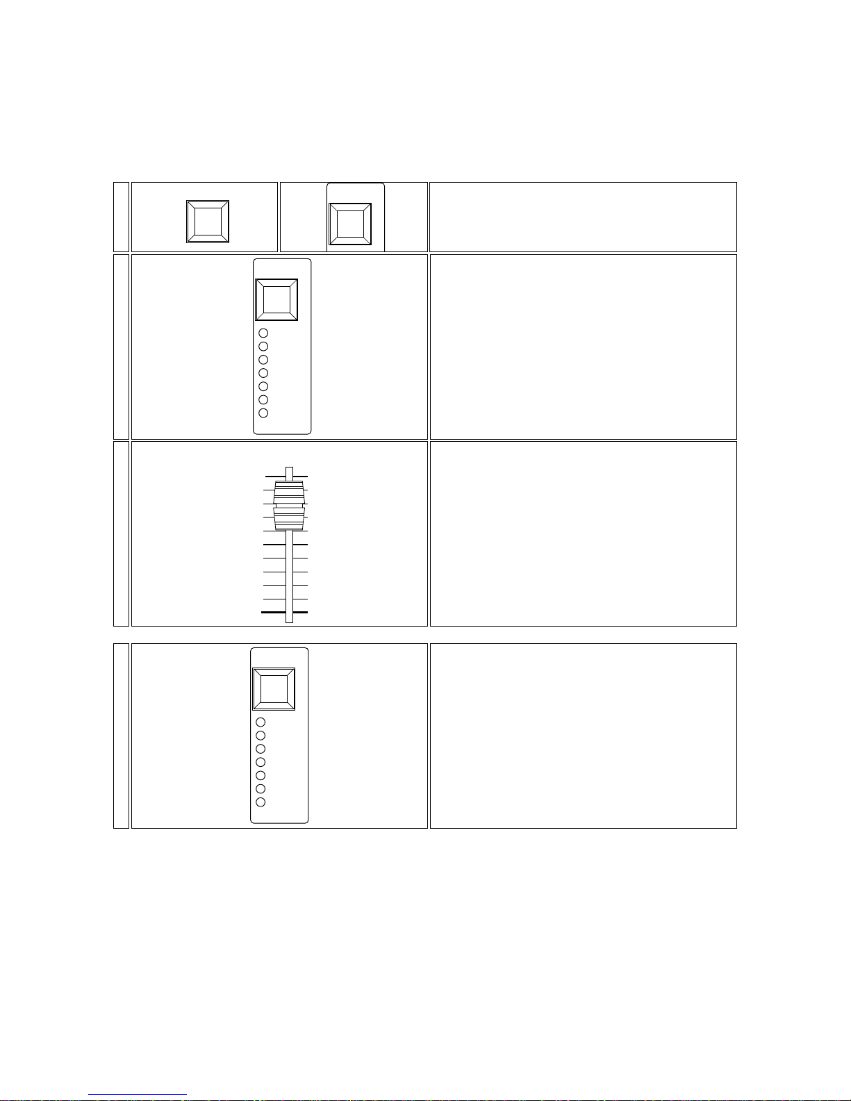
9.3. Outputting an effect
In the previous sections 9.1 and 9.2 various chase effects were generated and previewed on the leds, these effects are
yeat to be outputted to the fixtures connected via the DMX 512 ouput, nor were they previewed on the green output
leds.
If the effects are to your requirements, you can output them as follows.
If the effects to be outputted are multi zone (section 9.2), they can only be assigned to the first zone (channels 1 to 6 or
1 to 4); if the effect is a single zone (section 9.1), they can be asssigned to the first zone (channels 1 to 6 or 1 to 4) or
to the second zone (channels 7 to 12 or 7 to 10).
manual system 12 plus allows the effect being outputted to be alterered.
Press the mode/transfer button briefly, note that the
standby led comes on, indicating the chase has been
transferred to this button, and is now not being outputted.
Press the mode/transfer button once again and the
chase resumes once more.
crossfade
full
super auto
standby
audio
manual
direct
mode/
transfer
4-
Slide up the effects slider to achieve the output level you
require the chase to run at (either ouput to a connected
dimmer rack or to any DMX 512 device). At this point the
output leds will come on to mimic the effect being generated.
effects
100
0
10
20
30
40
50
60
70
80
90
3-
Note that after the effect has been transfered to the
mode/transfer button, the the effect and its parameters
are held in memory.
In this manner, the effects generator can continue to be used
to select new chase effects and then transfer these.
crossfade
full
super auto
standby
audio
manual
direct
mode/
transfer
2-
After having viewed the effect on the monitor leds, press the
transfer button in the effects generator group, whilst
simultaneously pressing the mode/transfer button in the
zone to which you wish to transfer the effect.
mode/
transfer
transfer
1-
Page 17
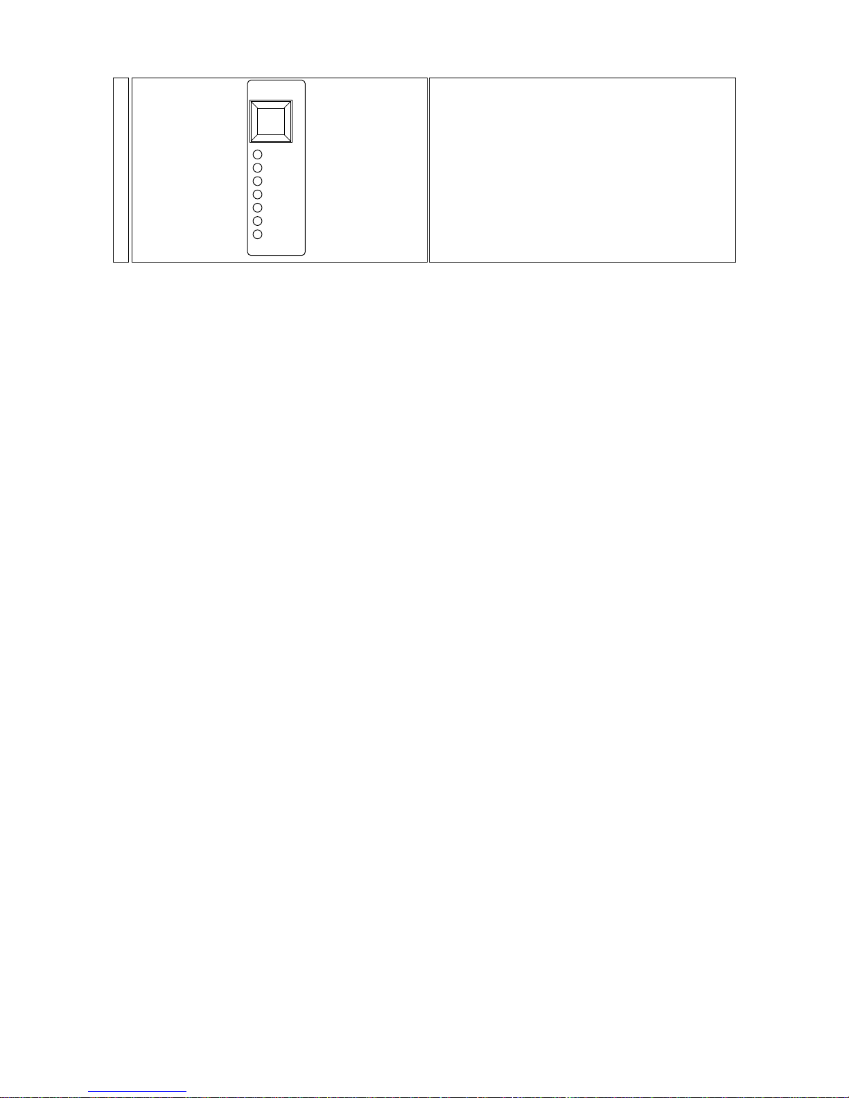
6- To reactivate a chase whose parameters you have altered, briefly press the mode/transfer button; the standby led will
go off.
Note: The chase speed (speed) is unable to be altered once it has been transferred; you will need to alter the speed
potentiometer (speed) in the effects generator and then repeat all the steps as described to this point.
Press and hold the mode/transfer for a few seconds;
note that the standby led comes on and allows several
parameters to be altered; you may choose from:
full: on/off only chase
crossfade: a crossfading chase
audio: sound-to-light, at either full or crossfade.
manual: manual stepping, at either full or crossfade,
activated by the+1 or -1.
direct: allows effects to be transfered directly from the
effects generator; without the need for pressing the transfer button.
standby: blacks out the current chase until the
mode/transfer button is pressed again.
crossfade
full
super auto
standby
audio
manual
direct
mode/
transfer
5-
Page 18
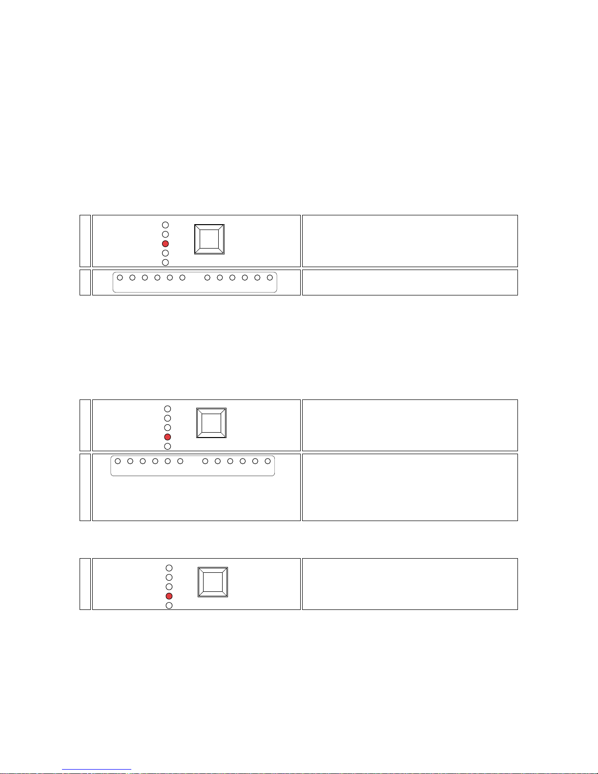
9.4. Effects generator advanced functions
Apart from the single zone and multi zone functions, the mode button allows the selection of various other functions
such as super auto, preview and clear all.
super auto
The super auto function is only used if an audio singnal is connected to the controller. This effect can be considered as one
which chases through different programs with time delays and attack being altered randomly and automatically. This effectivelly allows the lighting operator to be absent for a period of time.
Since the programs being run are selected randomly from memory, it is impossible, therefore, for any preview of the effect
which will be generated.
The super auto effect can can be generated and transferred to a single zone(6 channels) or to the whole controller.
When you wish to assign this function to a single zone, you must press the mode button until both the single zone and
the super auto leds come on. If, however, you wish to transfer the function to the whole controller, you must press the
mode button until both the multi zone and the super auto leds come on.
Transferring the single zone /super auto function to one zone of the controller allows you to have one zone running in a
totally automated manner, whilst the other remains under operator control.
3- Proceed now as discussed in section 9.3 if you wish to transfer the super auto function to the outputs of your
manual system 12 plus.
preview
Allows effects generated via the master effects slider to be previewed, without disrupting the live outputs
The preview leds will mimic any effects generated in, and transfered to outputs from, the effects generator, even if the
master effects slider is set to 0; in this way effects can be previewed and edited without affecting any live ouputs.
The levels set on preset A and preset B take control over chase effects when the master effects slider is active; in this
mode you have complete and real-time control over the output levels from the master effects slider.
clear all
Transferring this function of the effects generator will black out all outputs and will cause all the leds to turn themselves off,
this perhaps bein g a useful function when scenes change in a production.
2- Proceed now as discussed in section 9.3 if you wish to transfer the clear all function to the outputs of your manual
system 12 plus.
Press the mode button in the effects generator section
until the clear all led comes on.
mode
clear all
super auto
multi zone
preview
single zone
1-
The preview leds which mimic the effects generator will
now mimic outputs so that you may view what occurs
when the master effects slider is raised.
The output levels of the individual channels, whose levels are
controlled by the master A and B sliders, will take precedence over the output levels of the 12 channels of the manual
system 12 plus.
preview
123456 789101112
2-
Press the mode button in the effects generator section
until the preview led comes on.
mode
clear all
super auto
multi zone
preview
single zone
1-
The preview leds will come on and mimic the first of what
will be randomly selected chases.
preview
123456 789101112
2-
Press the mode button in the effects generator section
of the controller until the super auto and single or
multi zone leds come on (as desired).
mode
clear all
super auto
multi zone
preview
single zone
1-
Page 19
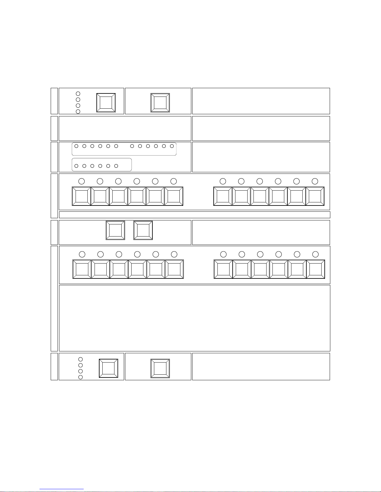
10. DMX patch
The DMX patch is used to assign any of the 72 channels that the manual system 12 plus can generate via the controllers on the front panels.
This function allows multiple fixtures to be assigned to a single slider, for example, several colour-changers with different
addresses, or unlimited dimmer rack channels which you may wish to operate in parallel.
We recommend that you read the following section 10.1 for a description of the function of the DMX patch move on to
section 10.2 for a description of how to modify the patch.
10.1 Viewing DMX channels assignments (patch)
We recommend that you practise the application of this function several times prior to moving on to the next section where
you will be instructed as to how to alter the various DMX channel assignments.
To return to normal operating mode, once again press the
mode and transfert buttons simultaneously, or simply
turn the controller off and on again.
transfer
mode
super auto
multi zone
preview
single zone
7-
The preview and DMX patch leds indicate the standard settings:
DMX 1 = channel 1 DMX 8 = channel 8
DMX 2 = channel 2 DMX 9 = channel 9
DMX 3 = channel 3 DMX 10 = channel 10
DMX 4 = channel 4 DMX 11 = channel 11
DMX 5 = channel 5 DMX 12 = channel 12
DMX 6 = channel 6 DMX 13 = channel 1
DMX 7 = channel 7 DMX 14 = channel 2
etc..,
this sequence of 12 channels is repeated up until the final channel able to be generated:
DMX 72 = channel 12.
flash flash
7 8 9 10 11 12
output
123456
output
6-
Press the flash master buttons to alter the active DMX
channel; the flash master A decrements, whilst the
flash master B increments; holding the button down
cause the increase/decrease to change rapidly.
flash master
5-
The slider to which that channel is assigned is represented by a lit output (gr een) led.
flash flash
7 8 9 10 11 12
output
123456
output
4-
The preview (yellow) led, together with the DMX patch
(green) led will represent active DMX 512 channel.
The preview leds represent units and the DMX patch leds
represent tens (eg. channel 52 is represented by green 50
and yellow 2 on simultaneously).
123456 789101112
10 20 30 40 50 60
123456 789101112
preview
dmx patch
3-
manual system 12 plus will test all the leds on the front
panel in turn, this will take approximately 30 seconds.
At the end of this test, the controller’s leds will all turn off
and the controller will be in DMX patch mode.
2-
Turn on the controller whilst holding down the mode and
transfert buttons
transfer
mode
super auto
multi zone
preview
single zone
1-
Page 20
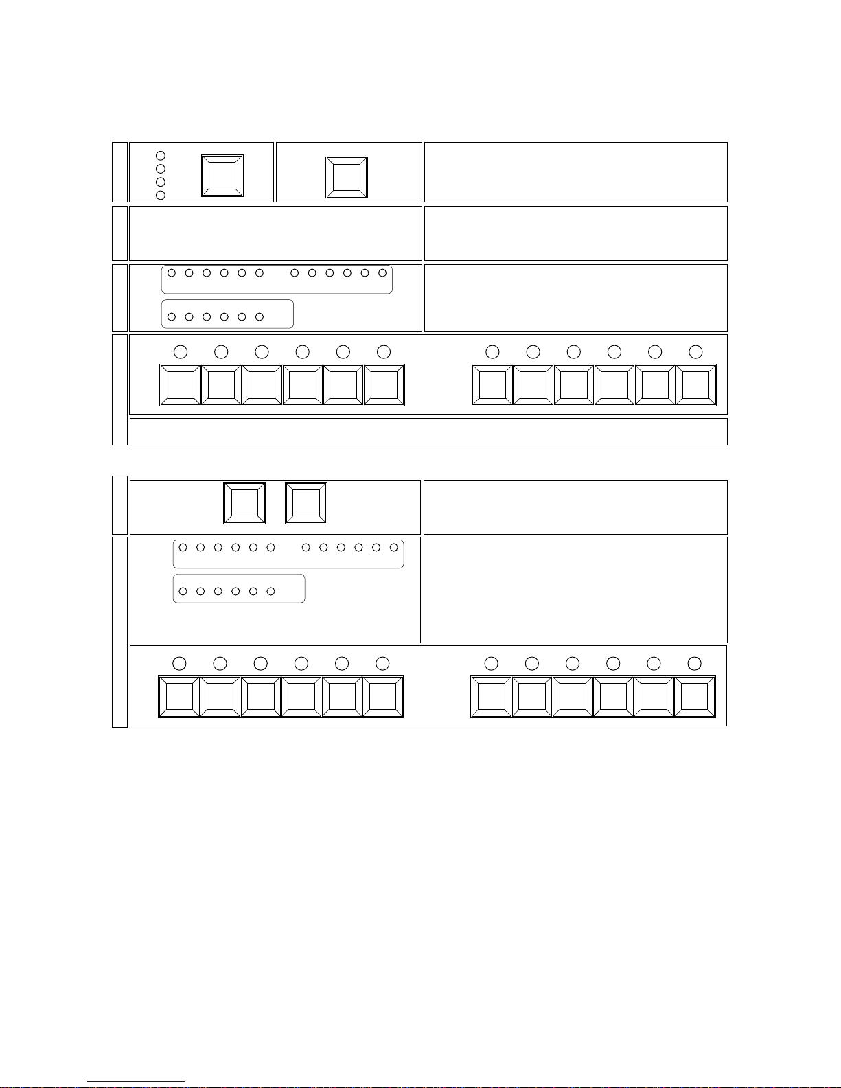
10.2 Altering DMX channel assignments (patch)
Make sure that you have read carefully through section 10.1 prior to attempting the following procedure.
ATTENTION: altering this function may compromise the operation of any DMX 512 device connected to the controller. It
should ony be utilised by a person with a thorough knowledge of the controller’s operation and the DMX 512 standards.
Note: All yellow preview leds will already have a channel assigned; pressing the flash button merely begins the proce-
dure for altering the current assignement.
Note: all 72 channels which the manual system 12 plus can be assigned to the same slider if you wish.
obviously, the converse cannot be true, any two sliders cannot be assigned to the same DMX channel if they are not in
separate presets.
Channels may also be assigned to the color, flash and strobe sliders.
flash flash
7 8 9 10 11 12
output
123456
output
With every press of a flash master (A or B), a new DMX
channel becomes active.
The preview leds represent units and the DMX patch leds
represent tens (eg. channel 31 is indicated by the green 30
led and the yellow 1 led being on simultaneously).
Select the next channels whose assignment you wish to
alter and then press the flash button of the channel to
which you wish it assigned.
123456 789101112
10 20 30 40 50 60
123456 789101112
preview
dmx patch
6-
Press the flash master buttons to alter the active DMX
channel; the flash master A decrements, whilst the
flash master B increments; holding the button down
cause the increase/decrease to change rapidly.
flash master
5-
Press the flash button of the channel you wish to assign as DMX channel 1; the corresponding output (green) led
will flash.
flash flash
7 8 9 10 11 12
output
123456
output
4-
The preview (yellow) led number 1 will come on to
indicate that DMX 1 is active.
123456 789101112
10 20 30 40 50 60
1 2 3 4 5 6 7 8 9 10 11 12
preview
dmx patch
3-
manual system 12 plus will test all the leds on the front
panel in turn, this will take approximately 30 seconds.
At the end of this test, the controller’s leds will all turn off
and the controller will be in DMX patch mode.
2-
Turn on the controller whilst holding down the mode and
transfert buttons
transfer
mode
super auto
multi zone
preview
single zone
1-
Page 21
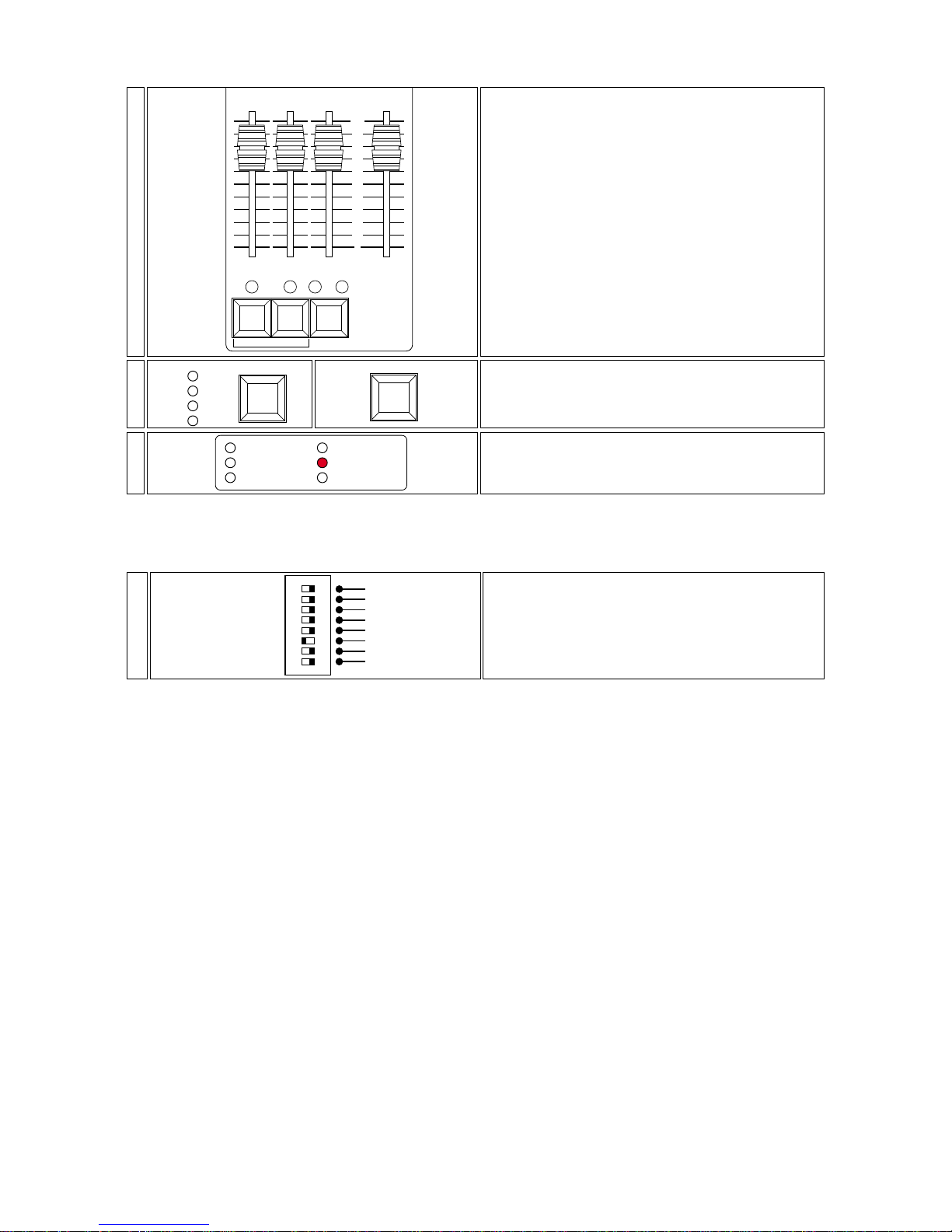
From this point on, all the functions previously referred to and any stored programs will behave normally, however the
DMX channels operating will depend on those assigned in the patch.
The patch lock dip-switch on the rear of the panel is there to avoid any accidental patch assignments being made.
Moving it to the ON position allows the patch you have just created to be locked in.
The patch lock dip-switch should be set to off if you wish to alter any DMX assignments.
Locate the dip-switches at the rear of the manual system
12 plus which, amongst other functions, allow patch
lock to be activated by setting the switch to ON.
Patch assignments can still be viewed, but cannot be altered.
dip-switch
optional
optional
optional
optional
flash inhibit
patch lock
strobo 7/12
strobo 1/6
ON
10-
A patch other than the default (hwere the first 12 DMX
channels correspond to the sliders in strict sequence DMX
1= channel 1,..... DMX 12= channel 12) will always be
indicated by the DMX patch led being on.
DMX 512 out
audio in
+20 V DC
flash inhibit
DMX patch
strobe setting
9-
Simultaneously press the mode and transfert buttons
to return the manual system 12 plus to normal operating mode. The new assignments are recoded in memory.
transfer
mode
super auto
multi zone
preview
single zone
8-
The +1 button assigns to the frost slider.
The -1 button assigns to the strobe slider.
The color button assigns to the color slider.
Upon pressing the frost, strobe or color buttons, the led
should come on to indicate the assigning of the selected
DMX channel.
Note: The strobe slider is automatically assigned the DMX
channel assigned its preset if the dip-switche strobe on
the rear of the unit are set to on (for more inofrmation see
sections 10 and 11).
color-1+1
random music
100
0
10
20
30
40
50
60
70
80
90
-1
+1
frost strobe color effects
7-
Page 22
11. Controlling the str obe effect of a motorised projetor
The strobe function allows the dimming function of a zone of 6 channels or of the whole controller to be altered.
This function is designed primarily for projectors which use a mechanical shutter for either dimming or strobe purposes;
using a DMX value of between 0 and 125 for dimming and between 150 and 245 for variable speed strobing.
ATTENTION!: activating this function can alter the proper operation of any DMX 512 devices connected. Tuld only be utilised by experienced DMX 512 device operators.
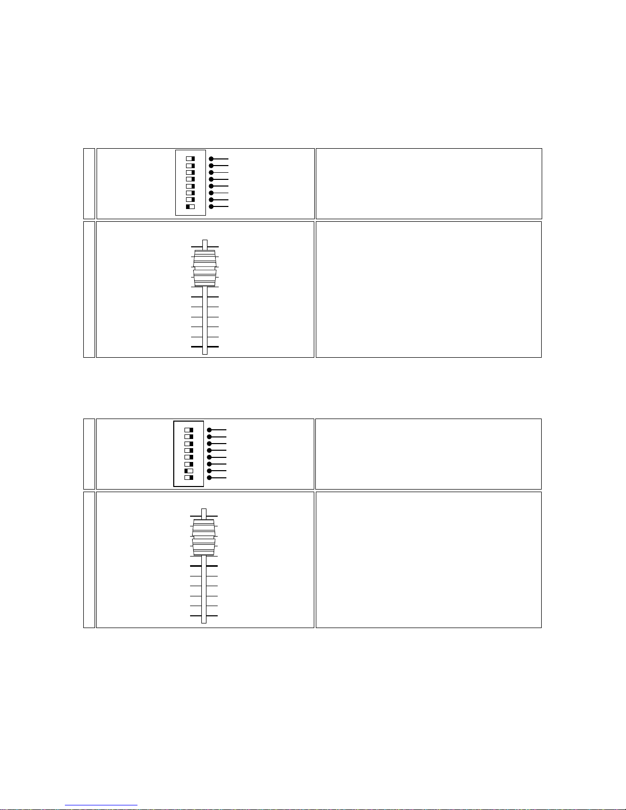
Two dip-switchs at the rear of the controller, strobe 1-6 and strobe 7-12 allow this function to be activated.
11.1 Zone 1 (sliders1 to 6)
With this modification, you may now assign the chases created in the effects generator to any motorised projectors (for
example, to the tas colore) which behave in a similar manner to a normal incandescent luminaire.
The strobe effect can be operated across all the assigned channels simultaneously via the strobe slider.
11.2 Zone 2 (sliders 7 to 12)
Note: The strobe slider can also be assigned to any channel selected via the DMX patch. function. In this case its level
will vary through 0 and 255 and it will be unaffected by any chases created.
Automatically, the strobe slider is now able to alter the
DMX level from 150 to 245 on all the DMX channels
now assigned to sliders 7 to 12. (or from 1 to 12 if all dipswitches strobe 1-6 and 7-12 are set to on.
strobe
2-
Locate on the rear of the manual system 12 plus the dipswitches marked strobe 7-12.
Set this dip-switch to ON; the DMX channels now assigned
to the sliders 7 to 12 will now adjust intensity from 0 to
125.
dip-switch
optional
optional
optional
optional
flash inhibit
patch lock
strobo 7/12
strobo 1/6
ON
1-
Automatically, the strobe slider is now able to alter the
DMX level from 150 to 245 on all the DMX channels
now assigned to sliders 1 to 6.
strobe
2-
Locate on the rear of the manual system 12 plus the dipswitches marked strobe 1-6.
Set this dip-switch to ON; the DMX channels now assigned
to the sliders 1 to 6 will now adjust intensity from 0 to
125.
dip-switch
optional
optional
optional
optional
flash inhibit
patch lock
strobo 7/12
strobo 1/6
ON
1-
Page 23
12. Controlling colour selection in a motorised pr ojector
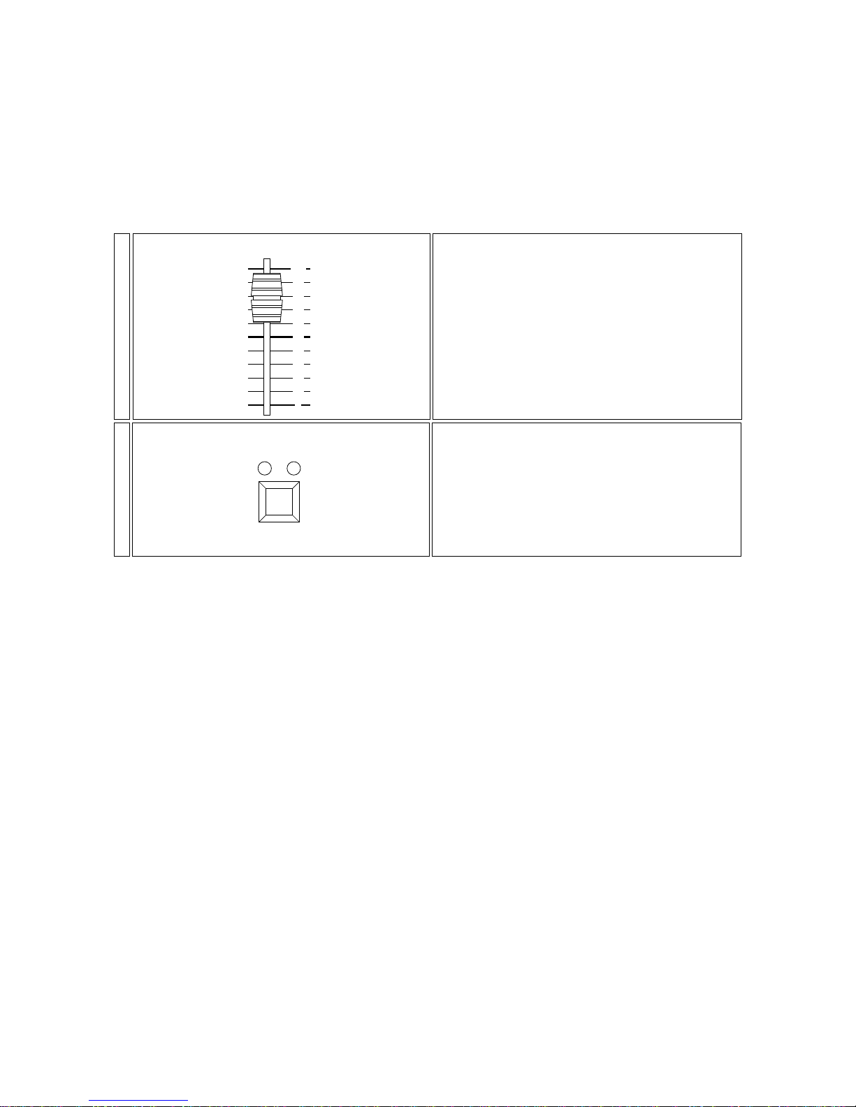
The color slider has several functions which make it extremely useful for controlling colour selection in a motorised projector.
This function allows operators to control colour changes manually, in a random mode (random), or in sound-to-light mode
(music).
Note: The color slider, as with the frost, can be assigned to be a colour change channel or simply a normal channel; for
example as a reset channel for motorised effects or, indeed, any other function which the user does not want included in
chases created in and transferred from the effects generator.
1- For color slider functions involving a motorised projector, you must first assign the channels which you want to control
via the DMX patch facility described in section 10.
Note that if the effect you wish to obtain from the fixtures being controlled by the manual system 12 plus soley colour
changing, simple colour changing can be achieved by any slider having the appropriate channel assignment made via the
DMX 512 patch.
Press the color button until the random led comes on.
The DMX channels assigned to the color slider will receive
a random selection of DMX signal which takes precedence
over the action of the color slider.
Press the color button until the music led comes on.The
DMX channels assigned to the color slider will receive
DMX signal which is synchronized to the beat of the audio
signal connected and takes precedence over the slider’s
action; to take full advantage of either the random or
color functions, the color slider should be set to 0.
color
random music
3-
The color slider allows the DMX levels of channels assigned to it to be altered.
The action is fully proportional over the travel of the slider.
100
0
10
20
30
40
50
60
70
80
90
color
2-
Page 24
13. manual system 12 plus as a controller for:
tas Colore a.t. 20° - Colore fresnel - VersìColore
The functions described in sections 10, 11 and 12 have varied and multiple uses. They make the manual system 12
plus particularly adept at controlling the functions of the tas Colore range.
The following descriptions may be considered as typical, but not exhaustive, examples which you may care to apply; and
the possibilities increase significantly if you are taking full advantage of the DMX patch facility described in section 10 and
are aware of the advantages afforded by the use of DMX 512.
The following examples use the manual system 12 plus to control three different types of lighting projector:
13.1 tas Colore a.t. 20°
13.2 tas Colore fresnel
13.3 tas VersìColore
13.1 tas Colore a.t. 20°
You may control Colore a.t. 20° projectors using any of the functions of the manual system 12 plus.
The descriptions for these functions have all been previously described in a genereic sense in preceding sections of this
manual; the following are summary descriptions.
Following these settings will make control of the fixture particularly simple.
settings on the Colore a.t. 20°
Each tas Colore a.t. 20° utilises 3 address channels for complete control of its functions via DMX 512:
Channel 1: dimmer/strobe
Channel 2: color
Channel 3: reset (from 20 to 50%) and proportional colour wheel control (from 50 to 80%)
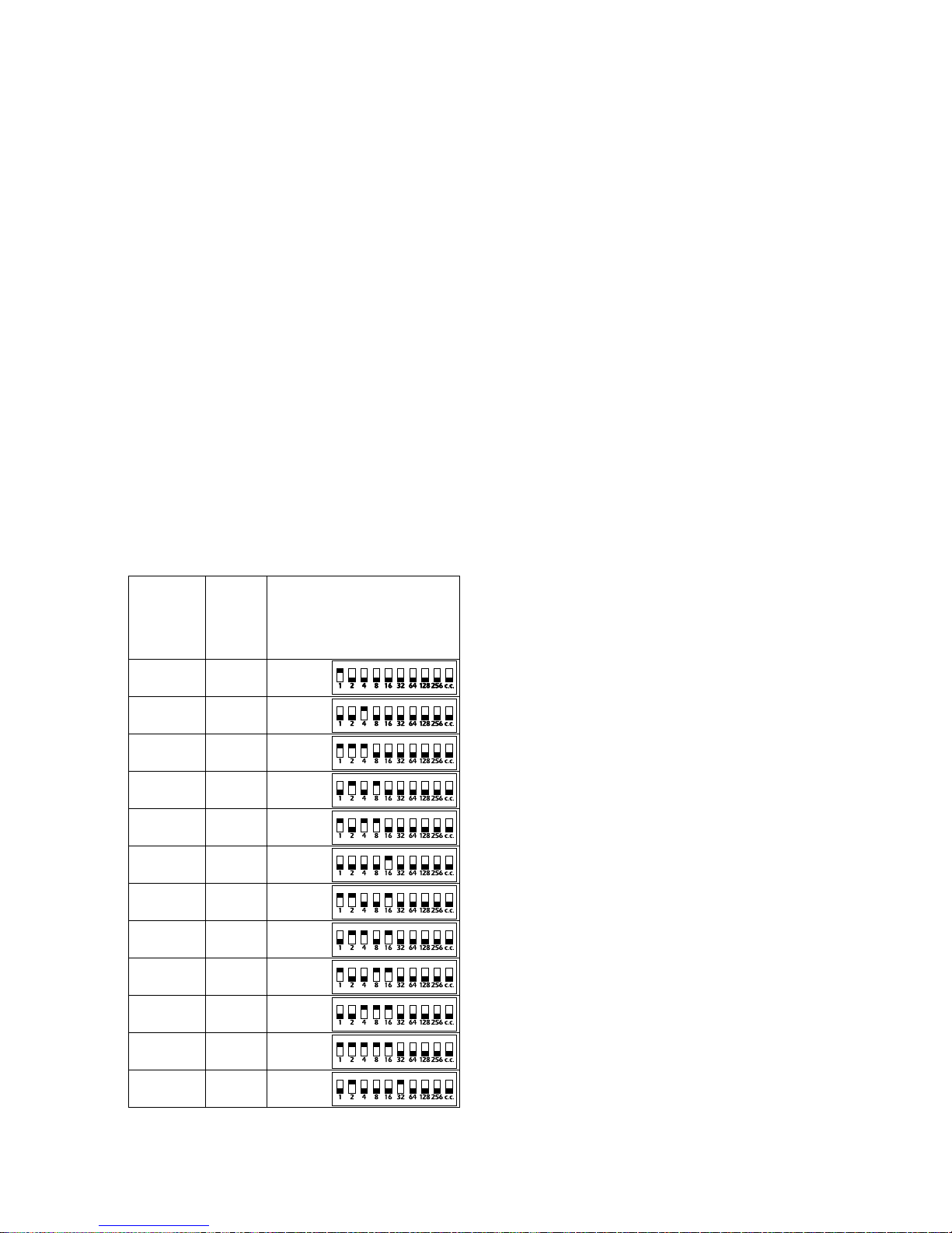
To ensure that each projector receives the correct signal , each unit must be correctly addressed; any number between 1
and 70 (manual system 12 plus can address its DMX to a maximum address of 72). This can be set on the projectors
via the dip-switches on each unit.
This procedure should be undertaken on every Colore a.t. 20° by setting the dip-switches to on or off according to the
simplified table shown below . To be effective, it should be done when the projector is switched off.
N.B. The 10° dip-switch should be set to OFF
an example of dip-switch setting for 12 Colore a.t. 20°
This table may also be used if a lesser number of Colore a.t. 20° are being used.
01 01 1
02 04 4
03 07 1-2-4
04 10 2-8
05 13 1-4-8
06 16 16
07 19 1-2-16
08 22 2-4-16
09 25 1-8-16
10 28 4-8-16
11 31 1-2-4-8-16
12 34 2-32
numero
DMX/
DMX
number
numero
proiettori/
projector
number
dip-switches
Page 25
settings to be made on the manual system 12 plus to control 12 Colore a.t. 20°
The following settings should be made on the manual system 12 plus to allow complete control over 12 Colore a.t
20°.; these settings will not be effective unless the changes to the dip-switches on the projectors have been made as advi-
sed above.
Upon completion of this procedure, the following functions will be available on the controller:
- The 12 preset A and B sliders will control the output of the projectors.
- The strobe slider will control the speed of the strobe effect.
- The color slider and the relative random and music buttons will control the colour selections.
- The frost slider will allow the colour wheel to be controlled proportionally (from 50 to 80%) or to reset all the projectors
(from 20 to 50%).
an example of dip-switch settings on the controller for 12 tas Colore a.t. 20°”
This table may also be used if a lesser number of Colore a.t. 20° are being used.
funzione di
Colore at 20°/
functions
Colore at 20°
ch 01 dimmer/shutter preset 1
ch 02 colour colour
ch 03 function frost
ch 04 dimmer/shutter preset 2
ch 05 colour colour
ch 06 function frost
ch 07 dimmer/shutter preset 3
ch 08 colour colour
ch 09 function frost
ch 10 dimmer/shutter preset 4
ch 11 colour colour
ch 12 function frost
ch 13 dimmer/shutter preset 5
ch 14 colour colour
ch 15 function frost
ch 16 dimmer/shutter preset 6
ch 17 colour colour
ch 18 function frost
ch 19 dimmer/shutter preset 7
ch 20 colour colour
ch 21 function frost
ch 22 dimmer/shutter preset 8
ch 23 colour colour
ch 24 function frost
ch 25 dimmer/shutter preset 9
ch 26 colour colour
ch 27 function frost
ch 28 dimmer/shutter preset 10
ch 29 colour colour
ch 30 function frost
ch 31 dimmer/shutter preset 11
ch 32 colour colour
ch 33 function frost
ch 34 dimmer/shutter preset 12
ch 35 colour colour
ch 36 function frost
canali/
channels
Assegnazione
sul pannello
frontale/
front pannel
devices
Assign the DMX channels via the front controllers as described in section 10, following the instructions in the table
below. Note that once the DMX patch facility is engaged:
A- The DMX channels are displayed via the preview (yellow) leds and the DMX patch (green) leds.
B- DMX channels are altered via the flash master A and flash master B.
C- A ll DMX channels are assigned by pressing the flash button on each channel.
2-
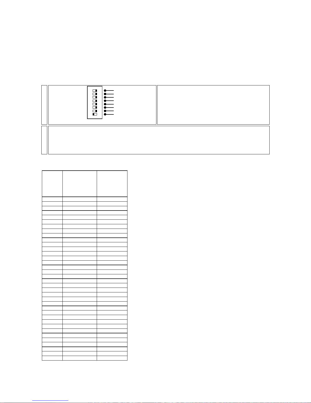
On the rear of the manual system 12 plus the dip-switches can be set to allow the functions strobo 1-6 and
strobo 7-12.
Set the dip-switches to ON; the DMX channels assigned to
sliders 1 to 12 now output levels from 0 to 125. The strobe effect is now assigned to the strobe slider.
dip-switch
optional
optional
optional
optional
flash inhibit
patch lock
strobo 7/12
strobo 1/6
ON
1-
Page 26
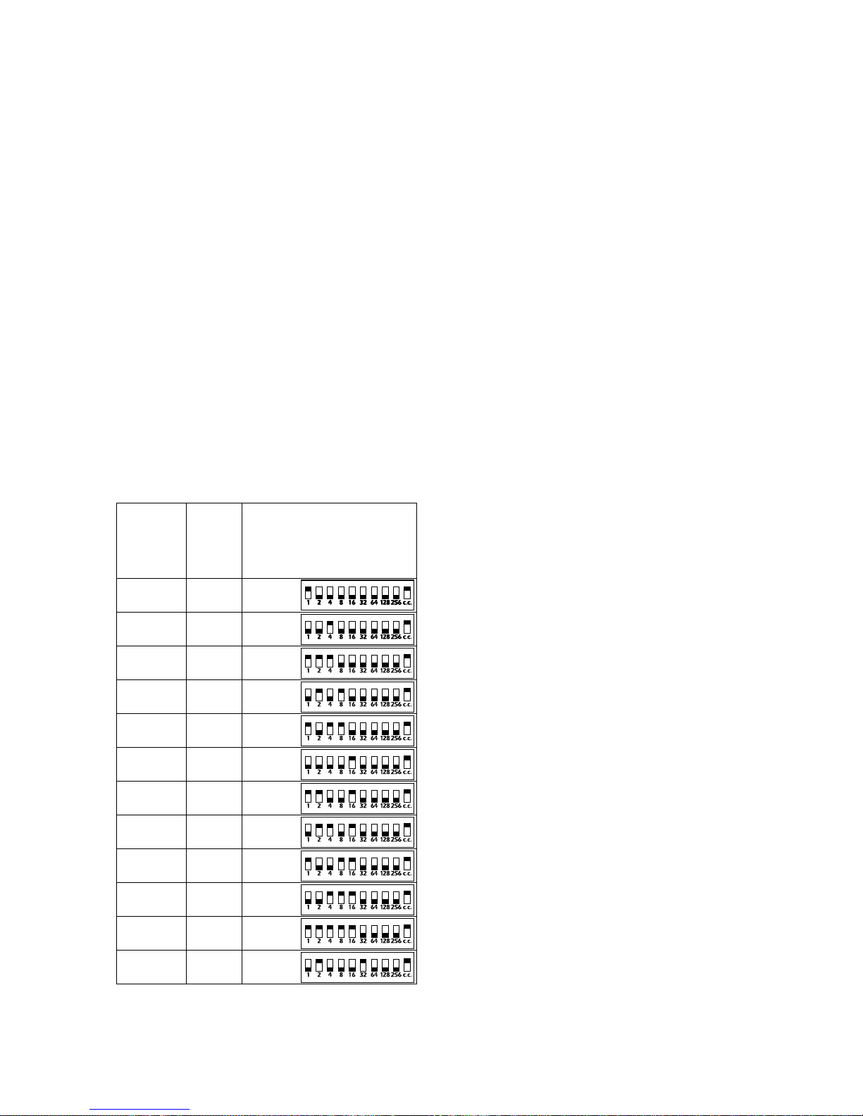
You may now exit the DMX patch function and control your Colore a.t.20°.
As you will have noted, the ability to assign different patch configurations affords great potential in control; ne abbiamo our
examples list only a few; should you encounter any difficulties with the procedure, you may confidently refer your enquires
to an authorised coemar service centre, who will be able to advise you of the required DMX 512 settings required for you
particular application.
13.2 tas Colore fresnel
You may control Colore fresnel using any of the functions availble on the manual system12 plus.
The descriptions for these functions have all been previously described in a genereic sense in preceding sections of this
manual; the following are summary descriptions.
Following these settings will make control of the fixture particularly simple.
settings on the tas Colore fresnel
Colore fresnel utilises 4 channels of DMX 512; it is possible to control up to 12 of these units completely using teh func-
tions of the manual system 12 plus via the sole compromise of using them in “compact channel” mode; this procedure is the most complex that needs to be performed and is explained in detail below.
In “compact channel” mode (dip-switch number 10 ON), each tas Colore fresnel utilises 3 channels of DMX 512
signal for complete control of the projectors functions:
Channel 1: dimmer/strobe
Channel 2: frost
Channel 3: color
To ensure that each projector receives the correct signal , each unit must be correctly addressed; any number between 1
and 70 (manual system 12 plus can address its DMX to a maximum address of 72). This can be set on the projectors
via the dip-switches on each unit.
This procedure should be undertaken on every Colore fresnel by setting the dip-switches to on or off according to the
simplified table shown below . To be effective, it should be done when the projector is switched off.
N.B. The number 10° dip-switch must be set to ON
an example of dip-switch settings for 12 Colore fresnel
This table may also be used if a lesser number of Colore fresnel are being used.
01 01 1
02 04 4
03 07 1-2-4
04 10 2-8
05 13 1-4-8
06 16 16
07 19 1-2-16
08 22 2-4-16
09 25 1-8-16
10 28 4-8-16
11 31 1-2-4-8-16
12 34 2-32
numero
DMX/
DMX
number
numero
proiettori/
projector
number
dip-switches
Page 27
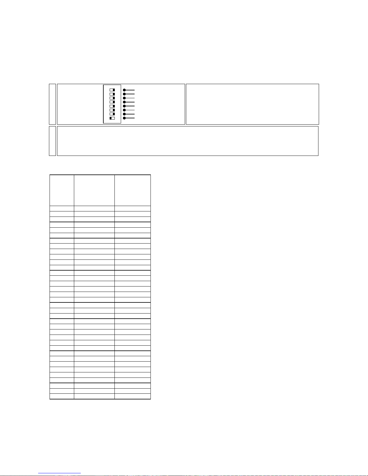
settings to be made on the manual system 12 plus to control 12 tas Colore fresnel
The following settings should be made on the manual system 12 plus to allow complete control over 12 Colore fresnel; these settings will not be effective unless the dip-switches on the projectors have been made as advised above.
Upon completion of this procedure, the following functions will be available on the controller:
- The 12 preset A and B sliders will control the output of the projectors.
- The strobe slider will control the speed of the strobe effect.
- The color slider and the relative random and music buttons will control the colour selections.
- The frost slider will allow you to adjust the beam angle by activating the frost filter effect in all the projectors connected.
an example of dip-switch settings on the controller for 12 tas Colore fr esnel
This table may also be used if a lesser number of Colore fresnel are being used.
You may now exit the DMX patch function and control your Colore fresnel.
As you will have noted, the ability to assign different patch configurations affords great potential in control; ne abbiamo our
examples list only a few; should you encounter any difficulties with the procedure, you may confidently refer your enquires
to an authorised coemar service centre, who will be able to advise you of the required DMX 512 settings required for you
particular application.
ch 01 dimmer/shutter preset 1
ch 02 frost frost
ch 03 colour colour
ch 04 dimmer/shutter preset 2
ch 05 frost frost
ch 06 colour colour
ch 07 dimmer/shutter preset 3
ch 08 frost frost
ch 09 colour colour
ch 10 dimmer/shutter preset 4
ch 11 frost frost
ch 12 colour colour
ch 13 dimmer/shutter preset 5
ch 14 frost frost
ch 15 colour colour
ch 16 dimmer/shutter preset 6
ch 17 frost frost
ch 18 colour colour
ch 19 dimmer/shutter preset 7
ch 20 frost frost
ch 21 colour colour
ch 22 dimmer/shutter preset 8
ch 23 frost frost
ch 24 colour colour
ch 25 dimmer/shutter preset 9
ch 26 frost frost
ch 27 colour colour
ch 28 dimmer/shutter preset 10
ch 29 frost frost
ch 30 colour colour
ch 31 dimmer/shutter preset 11
ch 32 frost frost
ch 33 colour colour
ch 34 dimmer/shutter preset 12
ch 35 frost frost
ch 36 colour colour
funzione di
Colore fresnel/
functions
Colore fresnel
canali/
channels
Assegnazione
sul pannello
frontale/
front pannel
devices
Assign the DMX channels via the front controllers as described in section 10, following the instructions in the table
below. Note that once the DMX patch facility is engaged:
A- The DMX channels are displayed via the preview (yellow) leds and the DMX patch (greeen) leds.
B- DMX channels are altered via the flash master A and flash master B.
C- A ll DMX channels are assigned by pressing the flash button on each channel.
2-
On the rear of the manual system 12 plus the dip-switches can be set to allow the functions strobo 1-6 and
strobo 7-12.
Set the dip-switches to ON; the DMX channels assigned to
sliders 1 to 12 now output levels from 0 to 125. The strobe effect is now assigned to the strobe slider.
dip-switch
optional
optional
optional
optional
flash inhibit
patch lock
strobo 7/12
strobo 1/6
ON
1-
Page 28
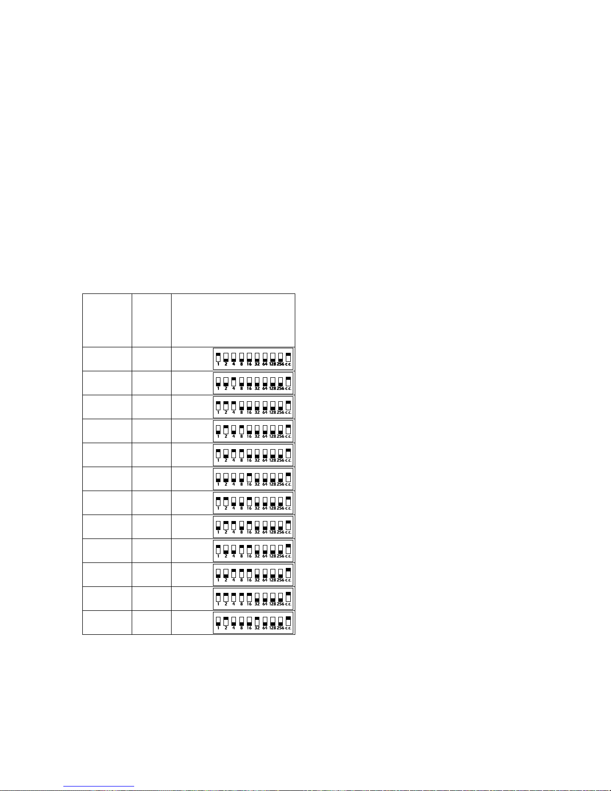
13.3 tas VersìColore
You may control tas VersiColore using any of the functions availble on the manual system12 plus.
The descriptions for these functions have all been previously described in a genereic sense in preceding sections of this
manual; the following are summary descriptions.
Following these settings will make control of the fixture particularly simple.
settings on the tas VersiColore
tas VersiColore utilises 5 channels of DMX 512; it is possible to control up to 12 of these units completely using teh func-
tions of the manual system 12 plus via the sole compromise of using them in “compact channel” mode; this procedure is the most complex that needs to be performed and is explained in detail below.
In “compact channel” mode (dip-switch number 10 ON), each tas VersiColore utilises 3 channels of DMX 512
signal for complete control of the projectors functions:
Channel 1: dimmer/strobe
Channel 2: frost
Channel 3: color
To ensure that each projector receives the correct signal , each unit must be correctly addressed; any number between 1
and 70 (manual system 12 plus can address its DMX to a maximum address of 72). This can be set on the projectors
via the dip-switches on each unit.
This procedure should be undertaken on every tas VersiColore by setting the dip-switches to on or off according to the
simplified table shown below . To be effective, it should be done when the projector is switched off.
N.B. The number 10° dip-switch must be set to ON
an example of dip-switch setting for 12 VersiColore
This table may also be used if a lesser number of Colore fresnel are being used.
settings to be made on the manual system 12 plus to control 12 tas VersiColore
The following settings should be made on the manual system 12 plus to allow complete control over 12 VersiColore
; these settings will not be effective unless the dip-switches on the projectors have been made as advised above.
Upon completion of this procedure, the following functions will be available on the controller:
- The 12 preset A and B sliders will control the output of the projectors.
- The strobe slider will control the speed of the strobe effect.
- The color slider and the relative random and music buttons will control the colour selections.
- The frost slider will allow you to adjust the beam angle by activating the frost filter effect in all the projectors connected.
01 01 1
02 04 4
03 07 1-2-4
04 10 2-8
05 13 1-4-8
06 16 16
07 19 1-2-16
08 22 2-4-16
09 25 1-8-16
10 28 4-8-16
11 31 1-2-4-8-16
12 34 2-32
numero
DMX/
DMX
number
numero
proiettori/
projector
number
dip-switches
Page 29
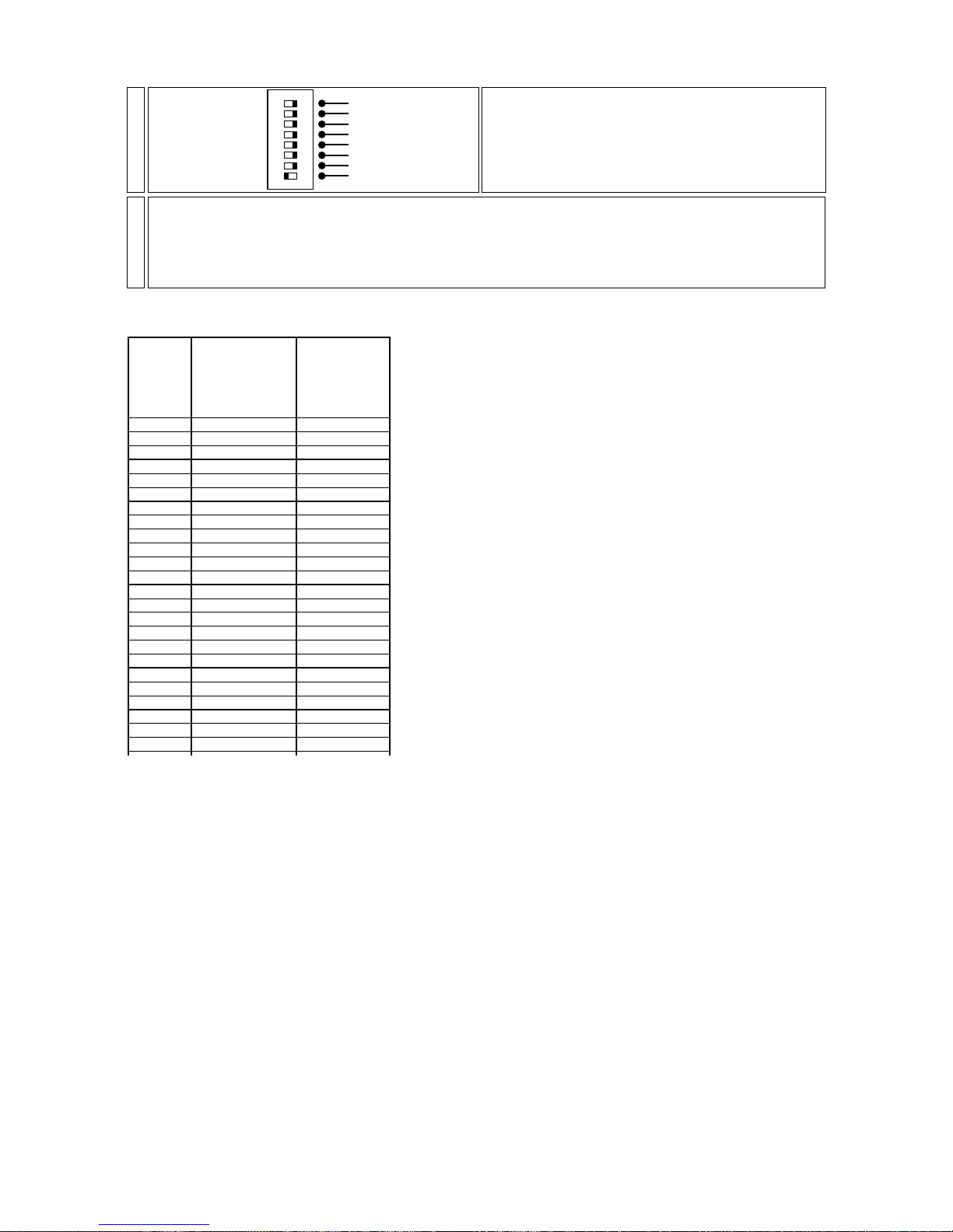
an example of dip-switch settings on the controller for 12 tas VersiColore
This table may also be used if a lesser number of VersiColore are being used.
You may now exit the DMX patch function and control your VersiColore.
As you will have noted, the ability to assign different patch configurations affords great potential in control; ne abbiamo our
examples list only a few; should you encounter any difficulties with the procedure, you may confidently refer your enquires
to an authorised coemar service centre, who will be able to advise you of the required DMX 512 settings required for you
particular application.
funzione di
Versìcolore/
functions
Versìcolore
ch 01 dimmer/shutter preset 1
ch 02 frost/cto frost
ch 03 colour colour
ch 04 dimmer/shutter preset 2
ch 05 frost/cto frost
ch 06 colour colour
ch 07 dimmer/shutter preset 3
ch 08 frost/cto frost
ch 09 colour colour
ch 10 dimmer/shutter preset 4
ch 11 frost/cto frost
ch 12 colour colour
ch 13 dimmer/shutter preset 5
ch 14 frost/cto frost
ch 15 colour colour
ch 16 dimmer/shutter preset 6
ch 17 frost/cto frost
ch 18 colour colour
ch 19 dimmer/shutter preset 7
ch 20 frost/cto frost
ch 21 colour colour
ch 22 dimmer/shutter preset 8
ch 23 frost/cto frost
ch 24 colour colour
canali/
channels
Assegnazione
sul pannello
frontale/
front pannel
devices
Assign the DMX channels via the front controllers as described in section 10, following the instructions in the table
below. Note that once the DMX patch facility is engaged:
A- The DMX channels are displayed via the preview (yellow) leds and the DMX patch (greeen) leds.
B- DMX channels are altered via the flash master A and flash master B.
C- A ll DMX channels are assigned by pressing the flash button on each channel.
2-
On the rear of the manual system 12 plus the dip-switches can be set to allow the functions strobo 1-6 and
strobo 7-12.
Set the dip-switches to ON; the DMX channels assigned to
sliders 1 to 12 now output levels from 0 to 125. The strobe effect is now assigned to the strobe slider.
dip-switch
optional
optional
optional
optional
flash inhibit
patch lock
strobo 7/12
strobo 1/6
ON
1-
Page 30
14. Dip-Switches
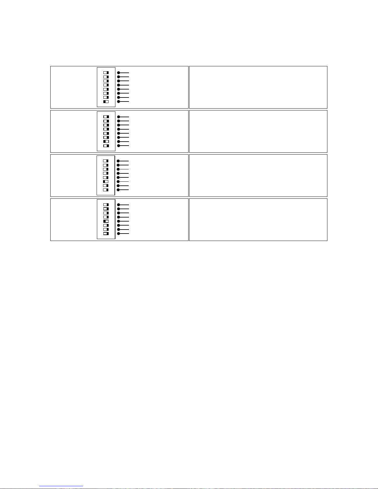
On the rear of the manual system 12 plus you will find 8 dip-switches, whose functions have been described previously in
this manual.
Their functions are summarised below, for your convenience.
I 4 The DIP-SWITCHES marked as optional have no functions in the current version.
Multiple dip-switches may be selected simultaneously, thus allowing multiple effects/inhibits to be selected as required.
flash inhibit inhibits the action of the flash buttons, thus
avoiding them being accidentally pressed during a show.
(Page. 15)
dip-switch
optional
optional
optional
optional
flash inhibit
patch lock
strobo 7/12
strobo 1/6
ON
patch lock locks up the dmx patch function to avoid it
being written over; this is particularly useful if a particular
patch assignment has been created for a specific show and
thus needs to be preserved.
(Page 22)
dip-switch
optional
optional
optional
optional
flash inhibit
patch lock
strobo 7/12
strobo 1/6
ON
strobo 7/12: alters the dmx ouput level range on channels 7 to 12, from 0/255 to 0/125 for normal operation.
The range from 150 to 245 of all 6 channels (7/12) are now
assigned to the strobe slider.
(Page 24).
dip-switch
optional
optional
optional
optional
flash inhibit
patch lock
strobo 7/12
strobo 1/6
ON
strobo 1/6: alters the dmx ouput level range on channels
1 to 6, from 0/255 to 0/125 for normal operation.
The range from 150 to 245 of all 6 channels (1/6) are now
assigned to the strobe slider.
(Page 24).
dip-switch
optional
optional
optional
optional
flash inhibit
patch lock
strobo 7/12
strobo 1/6
ON
Page 31
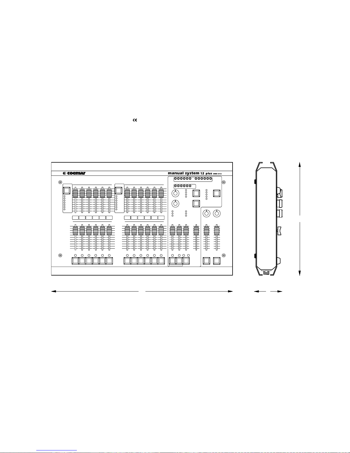
15. Technical characteristics
• maximum control of: 12 independent dimmer channels
12 independent tas Colore
• 72 digital DMX 512 output channels numbered 1 to 72
• Power supply: +20 V DC V via coaxial plug, (plug characteristics: Ø internal 2,1mm, Ø external 5,5mm).
• DMX 512 rate: 15 mS
• crossfade times (fade time A and B): from 0,1 to 200 seconds
• audio input level from 100 mV to 10V RMS via 2 pin RCA
• 8 bit microprocessor
• dust resistant,long life hi-endurance, auto lubricating sliders
• silver contact buttons
• DMX 512 ouput via XLR 5 socket
• Over-voltage powersupply protection
• 4 rubber feet
• Wall mountable fixing available
• weight 7,3 Kg
• complies with all recognised standards
• Dimensions:
309
496 76
Page 32
manual system 12 plus
16. Software version 3.1 update
The software version loaded in the manual system 12 plus can be determined when the console is powered up.
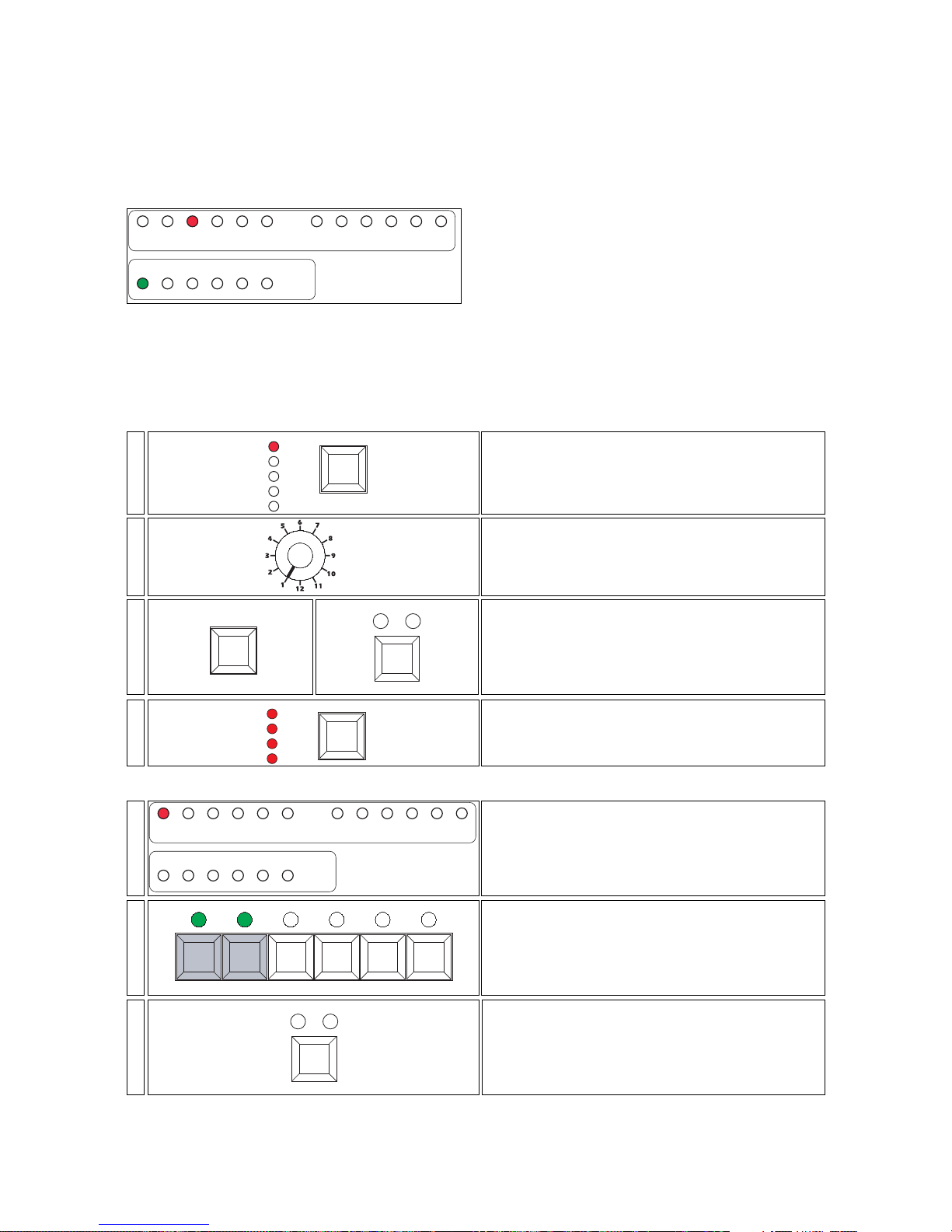
If software version 3.1 is loaded, the yellow preview 3 led and the green dmx patch 1 led will be on.
Version 3.1 adds several new features to the manual system 12 plus.
1. Programming sequential chase effects
Single zone or multizone sequential chase effects may be programmed.
This effect is programmable as effect 1, and is able to be selected by the rotary selector control.
The maximum number of steps in both the single zone and multizone effect is 60.
Programming a single zone effect
From this moment on, the preview led (indicating units) and the dmx patch led (indicating decimals), will indicate the
current program step; the green flash leds indicate steps currently held in memory.
Press the color button to confirm the recording of the first
step of the program.
color
random music
7-
Press the flash buttons in zone 1 (channels 1 to 6) corresponding to the channels you wish to have on as the first
step of the program, for example 1 and 2.
output
123456
flash
6-
The preview 1 led will come on to indicate that you are at
the first step of a recordable program.
The flash led indicates the first step of the program.
1 2 3 4 5 6 7 8 9 10 11 12
10 20 30 40 50 60
123456 789101112
preview
dmx patch
5-
All the trigger leds will come on to confirm that the console is in programming mode.
trigger
full
manual
crossfade
audio
4-
Simultaneously press the transfer button and the
color button.
color
random music
transfer
3-
Select the first sequential/chase program, using the rotary
selector.
selector
2-
Press the mode button in the effects generator bank
until the single zone led is on.
mode
clear all
super auto
multi zone
preview
single zone
1-
123456 789101112
10 20 30 40 50 60
123456 789101112
preview
dmx patch
Page 33
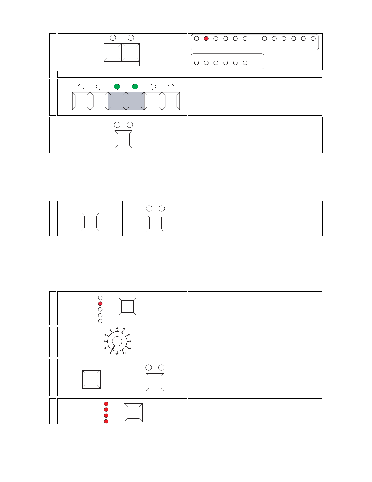
NOTE: The preview led will flash to indicate that you have created the first steps of a program which is as yet unrecorded
and saved, the flash leds will still show the last step of a previously recorded program.
You may continue the programming procedure for program 1, repeating the procedure outlined in steps 8 and 9 to a
maximum of 60 steps.
When you have completed the last step of the program you wish to record, you must terminate the program as described
in the following procedure step 11.
To view the recorded program, refer to section 9. Using pre-programmed effects.
Programming a multi zone effect
Multizone effects are those chases created across 12, 18 or 24 channels.
You may choose to program the manual system 12 plus across either 12 channels, depending upon teh arrangement
of the luminaires you wish to control.
After determining how many channels you wish your multi zone effect to operate on, proceed as follows:
All the trigger leds will come on to confirm that the console is in programming mode.
trigger
full
manual
crossfade
audio
4-
Simultaneously press the transfer button and the
color button.
color
random music
transfer
3-
Select the first sequential/chase program, using the rotary
selector.
selector
2-
Press the mode button in the effects generator bank until
the multi zone led is on.
mode
clear all
super auto
multi zone
preview
single zone
1-
Simultaneously press the transfer and color buttons to
conclude the programming process.
color
random music
transfer
11-
Press the color button to confirm the recording of the
second step of the program.
color
random music
10-
Press the flash buttons in zone 1 (channels 1 to 6) corre-
sponding to the channels you wish to have on as the
second step of the program, for example 3 and 4.
output
123456
flash
9-
,Press the +1 button to move to the second step of the program; the preview led 2 will come on.
123456 789101112
10 20 30 40 50 60
123456 789101112
preview
dmx patch
-1+1
8-
Page 34
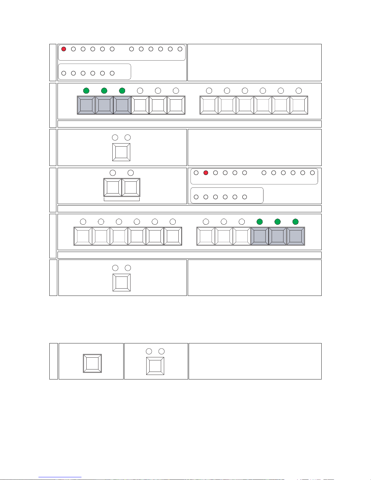
From this moment on, the preview led (indicating units) and the dmx patch led (indicating decimals), will indicate the
current program step; the green flash leds indicate steps currently held in memory.
NOTE: The preview led will flash to indicate that you have created the first steps of a program which is as yet unrecorded
and saved, the flash leds will still show the last step of a previously recorded program.
You may continue the programming procedure for program 1, repeating the procedure outlined in steps 8 and 9 to a
maximum of 60 steps.
When you have completed the last step of the program you wish to record, you must terminate the program as described
in the following procedure step 11.
To view the recorded program, refer to section 9. Using pre-programmed effects.
Simultaneously press the transfer and color buttons to
conclude the programming process.
color
random music
transfer
11-
Press the color button to confirm your recording of the
second step in the program.
color
random music
10-
Press the flash buttons corresponding to the channels you wish to have on in step 2, for example from 10 to 12
output
7 8 9 10 11 12
flash
output
123456
flash
9-
Press the +1 button to move to the second step of the program; the preview led 2 will come on.
123456 789101112
10 20 30 40 50 60
123456 789101112
preview
dmx patch
-1+1
8-
Press the color button to confirm your recording of the
step in the program.
color
random music
7-
Press the flash buttons corresponding to the channels you wish to have on in step 1, for example from 1 to 3
output
7 8 9 10 11 12
flash
output
123456
flash
6-
The preview 1 led will come on to indicate that you are at
the first step of a recordable program.
1 2 3 4 5 6 7 8 9 10 11 12
10 20 30 40 50 60
123456 789101112
preview
dmx patch
5-
Page 35
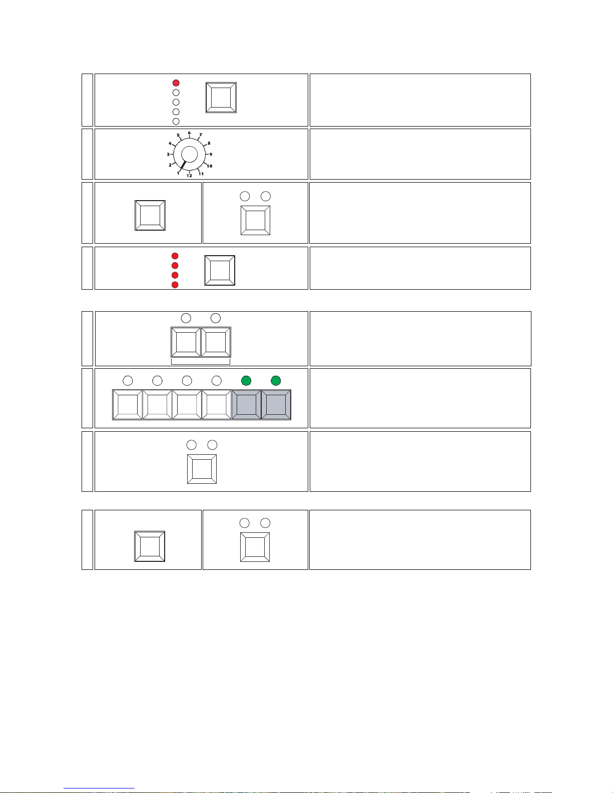
Modifying a step in a previously recorded program
If you wish to alter one or more steps of a previously recorded program, follow the procedure as outlined below.
From this moment on, the preview led (indicating units) and the dmx patch led (indicating decimals), will indicate the
current program step; the green flash leds indicate steps currently held in memory.
Repeat steps 5 to 7 to alter any other steps you may wish changed.
To view the recorded program, refer to section 9. Using pre-programmed effects.
Important note: manual system 12 plus will not allow you to exit the programming procecure if you have selected
an empty step, this will be indicated by a flashing preview led.
Step playback speed
In software version 3.1 the step playback (chase) speed is alterable via the speed potentiometer from 60 sec. (speed
1) to 0.1 sec.
Simultaneously press the transfer button and the
color button to conclude the editing procedure.
color
random music
transfer
8-
Press the color button to record your modification.
color
random music
7-
Press the flash button corresponding to the chan-
nel you wish to deactivate and then press that corresponding to the channel you wish to activate , for example,
5 and 6
output
123456
flash
6-
Press the +1 or -1 buttons until the step of the program
you wish to alter is displayed via the preview led.
-1+1
5-
All the trigger leds will come on to confirm that the console is in programming mode.
trigger
full
manual
crossfade
audio
4-
Simultaneously press the transfer and the color button.
color
random music
transfer
3-
Select the program sequential chase 1, via the rotary selec-
tor.
selector
2-
Press the mode button in the effects generator
bank until either the single zone or the multi zone
led comes on, depending upon the chase you
wish to modify.
mode
clear all
super auto
multi zone
preview
single zone
1-
Page 36

coemar reserves the right to effect modifications without prior notice
instruction manual
manual system 12 plus
1
st
edition july 1998
coemar spa
via Inghilterra
46042 Castelgoffredo (Mantova) Italy
T el. 0376/77521
Fax 0376/780657
 Loading...