

Page 1
SERVICE MANUAL
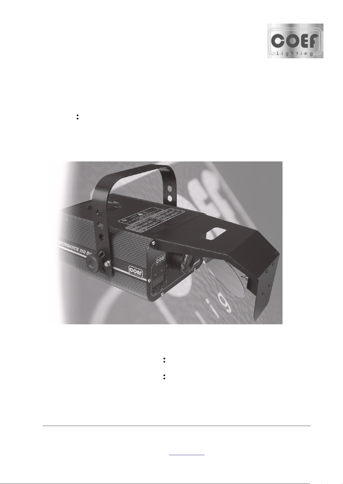
MODE PERFORMANCE250 DV/DVP
CODE ZL-012601-01
CODE ZL-012701-01
Address:Via Svizzera,12/14,Castel Goffredo Mantova 46042 Italy
Website: www.coef.it
Page 2

INDEX
COVER-------------------------------------------------------------------------------------------------.1
INDEX--------------------------------------------------------------------------------------------------.2
1.0 SPECIFICATIONS---------------------------------------------------------------------3
2.0 CHANNELS AND DIGITAL VALUES---------------------------------------------4
3.0 ASSEMBLY SKETCH AND PART LIST--------------------------------------------6
4.0 WIRE CONNECT DIAGRAM-------------------------------------------------------9
5.0 PCB COMPONENT LOCATION DRAWING------------------------------------10
6.0 ELECTRONIC MAINTENANCE--------------------------------------------------11
7.0 ORDINARY MAINTENANCE-----------------------------------------------------12
8.0 EXTRAORDINARY MAINTENANCE-----------------------------------------12
9.0 TROUBLE SHOOTING------------------------------------------------------------.13
COSTOMER SUPPORT REQUEST FORM-------------------------------------15
2
Page 3
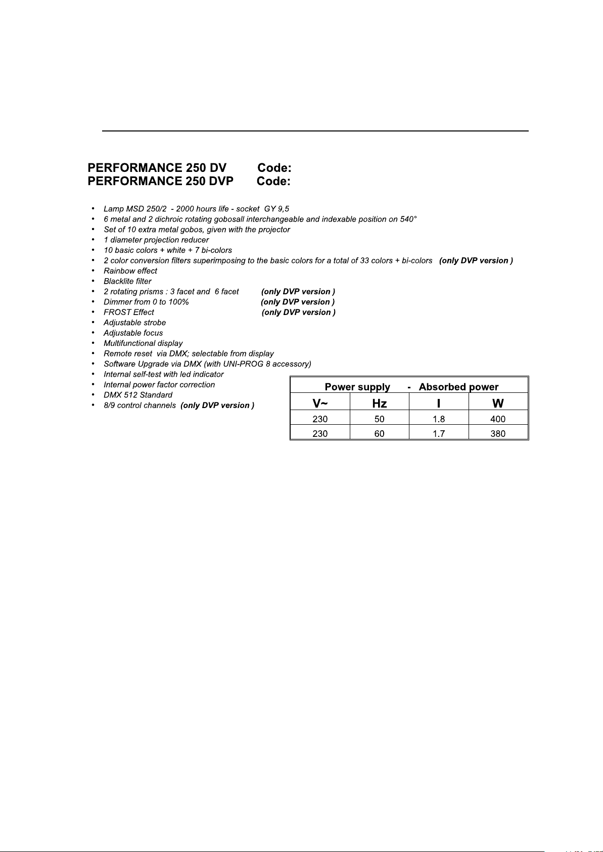
1.0 SPECIFICTION
ZL-012701-01
ZL-012601-01
3
Page 4
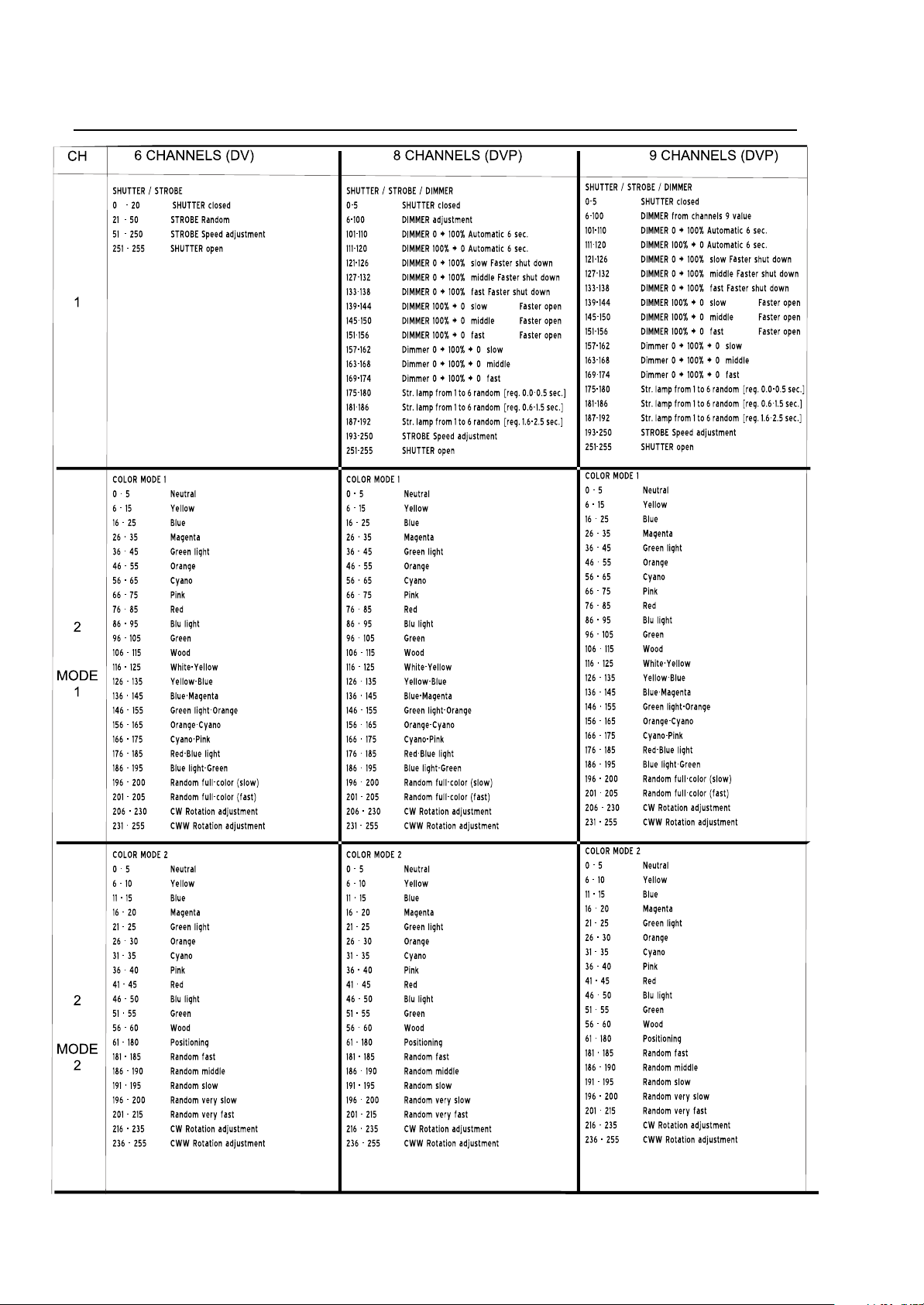
2.0 CHANNELS
AND
DIGITAL
VALUES
next
4
Page 5
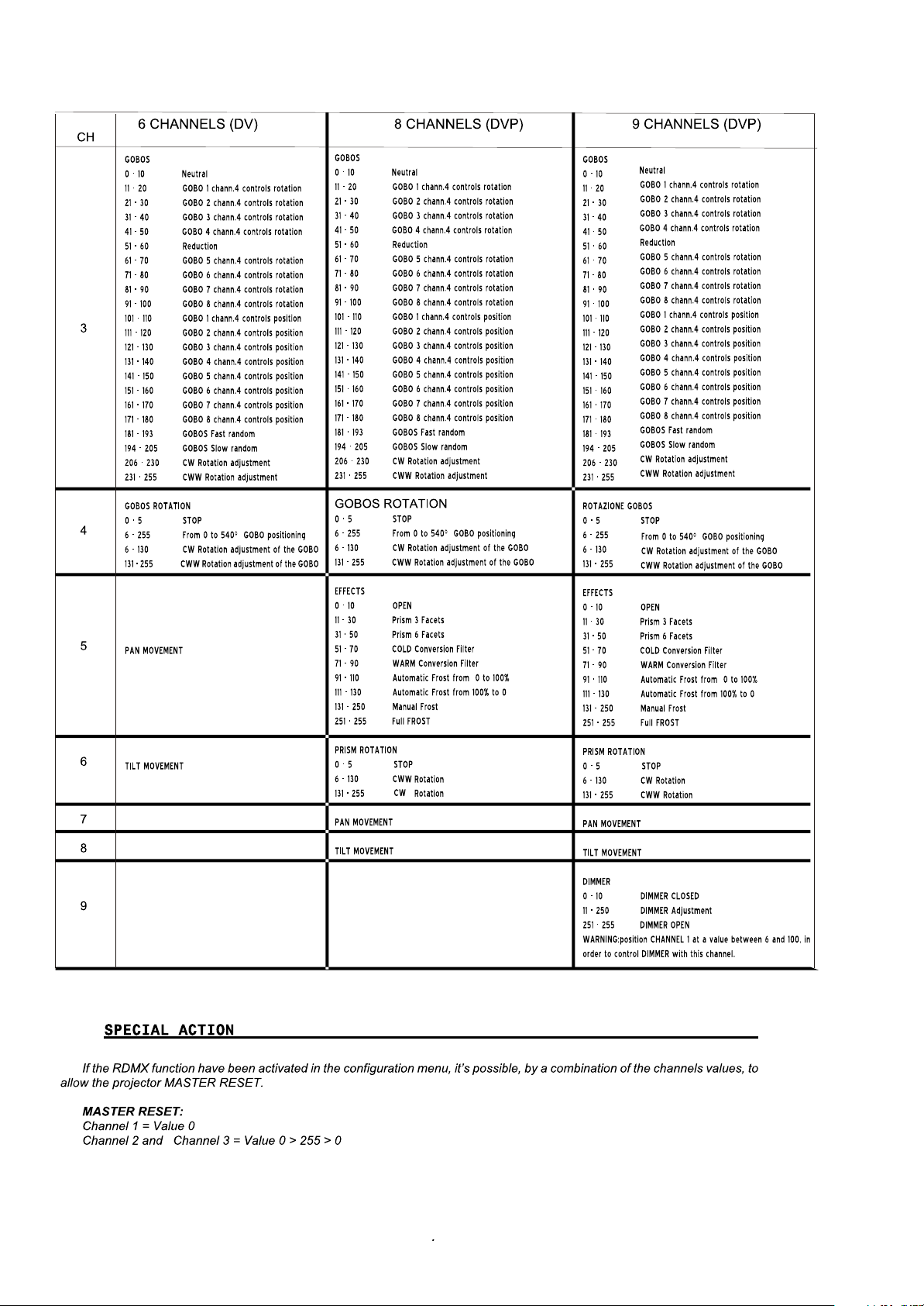
continue
5
Page 6

1
R/N P/N PART NAME DESCRIPTION QUA
1 126-0326000000 lampholder GY9.5 L=400mm 1
2 022-1014022254 transformer
100V-250V2*(28V
2A)
12V 1.8A
1
3 119-2523000600 ballast 230VAC50/60HZ 3A 1
4 013-4000412505 capacitor
40 F 250V
1
5 088-5001063400 ignitor 4-5KV,5A HQCD-7 1
6 370-5012301033 elliptic reflector
85.8* 26*44.3
1
7 083-0230000000 fan
119*119mm
230VAC/50/60HZ
1
8 088-5012601538 main pcb loaded 261×141mm 1
9 619-0126010000 objective lens assembly
75 400°
1
10 605-0000000019 step motor 5
11 626-0126010000 mirror assembly 125x175x1.2 ,R62.5 1
12 575-1009061900 focus adjustment 9*61mm 3
13 066-1080000000 thermal switch
80
1
14 626-0127012000 anti-heat filter(DV only) 153.5*80 1
13
3.0 ASSEMBLY SKETCH AND PARTS LIST
5
3
6
1
14
8
11
10
12
9
2
7
4
6
Page 7

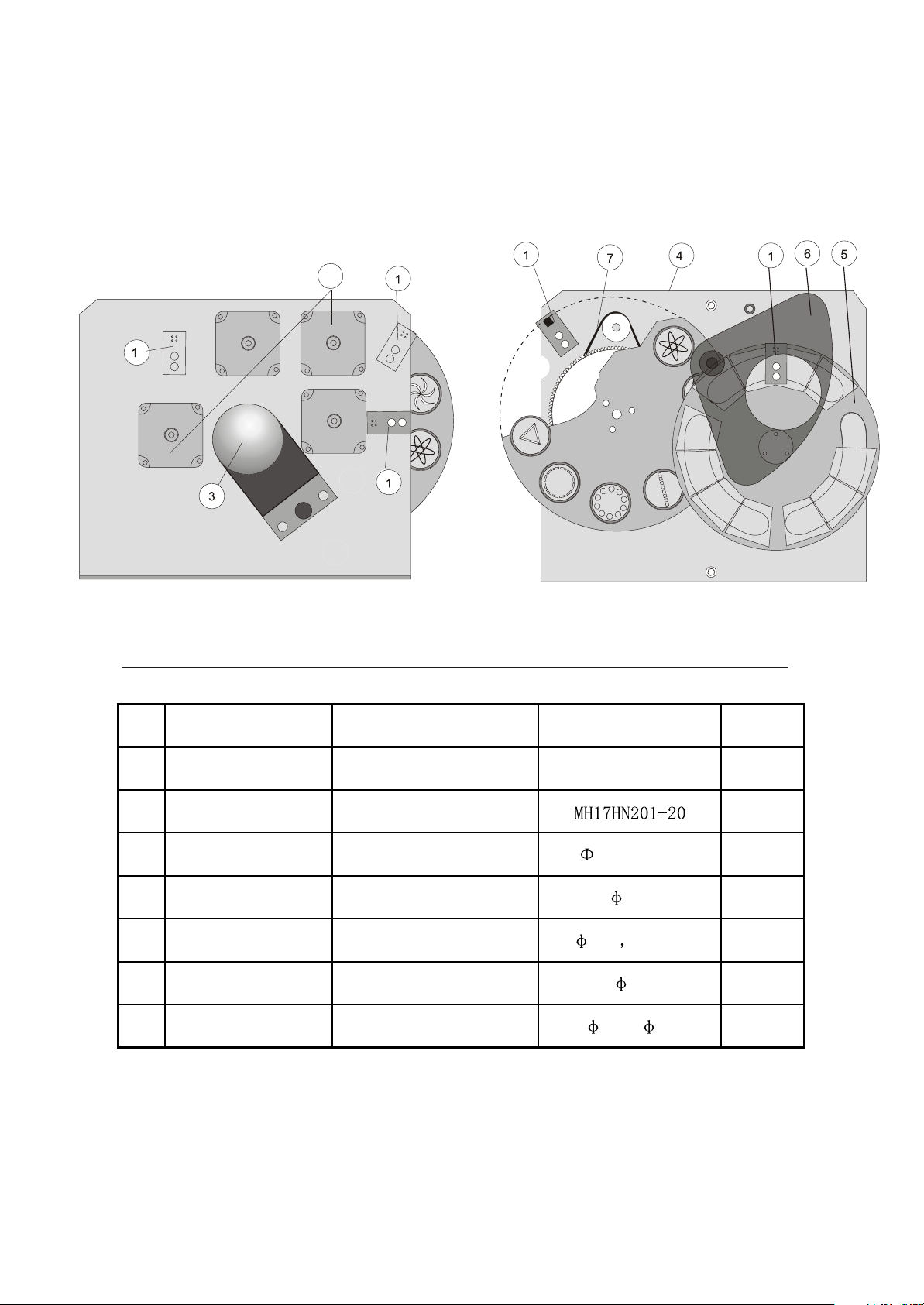
3.1 ASSEMBLY SKETCH AND PARTS LIST
R/N P/N PART NAME DESCRIPTION QUA
1 852-0740003500 OR-ring
3.53 57
1
2 622-0126010000 prism wheel assembly
151
1
3 605-0000000023 step motor MH17HN201-20 2
4 088-5020600490 optical sensor pcb assembly 26.7*26.76mm 4
5 618-0126010000 gobos wheel assembly
152
1
6 616-0126010000 focus lens assembly
49.8 1120°
1
7 852-0580003500 OR-ring
3.53 74
1
8 610-5012301000 shutter/strobe/dimmer blade 0.5mm 2
9 611-0126010000 color wheel assembly
138
1
10 624-5012601000 anti-heat filter assembly 70*164*1.2 1
(DVP ONLY)
4
21
3
54
7
4
8
9
4
6
5
3
12
10
6
Part list
7
Page 8
3.2 ASSEMBLY SKETCH AND PARTS LIST
R/N P/N PART NAME DESCRIPTION QUA
1 088-5020600490 optical sensor pcb loaded 26.7*26.76mm 4
2 605-0000000023 step motor 2
3 616-0126010000 focus adjustment assembly
49.8 1120°
1
4 618-0126010000 gobo wheel assembly
152
1
5 611-5012301000 color wheel assembly
138 11PCS
1
6 626-0127011000 shutter/strobe blade assembly
28
1
7 852-0580003500 OR-ring
3.53 74
1
(DV ONLY)
2
Part list
8
Page 9

4.0 WIRE CONNECT DIAGRAM
9
Page 10

5.0 PCB COMPONENT LOCATION DRAWING
10
Page 11

6.0 ELECTRONIC MAINTAENCE
This section is dedicated in detail to the electronic connection between the card and the mechanical
components,assembled in the projector .These informations will be absolutely necessary when the mechanical
unit has to be removed from the projector for maintence and/or repair.
The connections are made using handy connectors and are detailed where you can find indications about the
connection beteween a specific connector and specific component of the mechanical unit. This includes the motors
and the sensors of the various effects wheels(color,gobosprisms,,shutter etc.)
WARNING! An improper use of this documentation made by not specifically qualified staff
can damage irremediably theelectronic and/or mechanical components of the projector
11
Page 12

7.0
ORDINARY MANTENANCE
WARNING switch off the projector before operating
8.0 EXTRAORDINARY MAINTENANCE
To make an extraordinary maintenance, it is necessary thepresence of a generic or qualified mechanicaloperator,according to the type of the needed intervention.To make it
simple, we advice to completely extract the mechanical part of the PER-FORMANCE
250DV/DVP from its box: look figure where you can see the hexa-gonal screws (A&B)4 for
DV model and 3 for DVP model; the focus bracket screws(C)that have to removed,so that
you can extract the whole mechanical part,supportIng the motors and the various heels
(Effects, color, gobos). In this way it will be much more easy to observe
the different particulars that have to be cleaned and, at the same time,
The whole mechanical structure mounted with all its components shown.
You must particularly take care of the sensors which are really fundamental in the unit working.
The sensors are absolutely necessary when a general reset of the projector is needed. If this function
is not correctly executed, it will totally compromise the regular working of the projector, at least for
the group referred to the sensor itself.
The same situation eill occur in the case of the gobos wheel or the effects wheel.
The section shutter/strobe/dimmer does not use sensors during the reset positioning but it is conditioned by a mechanical beat of the shutter shovels.
You must carefully clean also the moving zoom lens. After several working hours dust and grease
will be stored on this lens, carried inside the projector by air flow.
12
Page 13
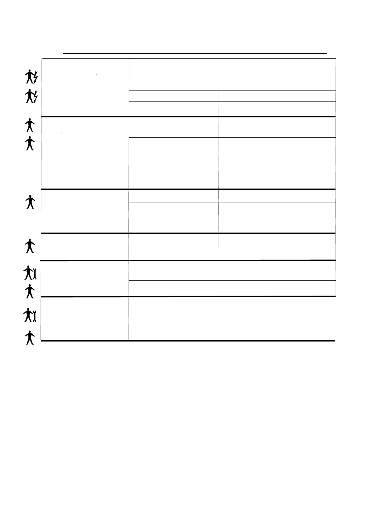
9.0
PROBLEM CAUSE ACTION
TROUBLE SHOOTING
The Projector doesn t switch on
The projector switches on but
doesn t answer to commands
Defecting projection
Projectionb with halo
-The power supply is not present
-The lamp is not working
The thermal switch is active Just to wait for little of time
-Wrong DMX configuration
-Defective cables
-Defective control unit
LED A is off Check the control unit&DMX cable
-The lens is broken
-Dust or grease stored on the all
parts of projector
-
- Dust or grease stored on the all
parts of projector
Check if the luminous indicator is lighted
or not.
Replace the lamp.
Make sure that the projector is correctly
configurated.
Replace or repair the DMX CABLE
Check the control unit by means of other
working projectors
Technical aid is required.
Check that the lens are not broken
Remove dust or grease stored on lenses
Carefully clean the optical group lenses
and the projector components
The color or other effects does
not coincide to the selected
value.
The PAN movement does not
coincide to the selected value
-Position senser dirty with dust or
grease
- Defective motor
- Electronic board
- Position senser dirty with dust or
grease
- Defective Motor
- Electronic board
Carefully clean the optical group lenses
and the projector components.
Technical aid is required.
Carefully clean the optical group lenses
and the projector components
Technical aid is required
13
Page 14

COSTOMER SUPPORT REQUEST FORM
If you have any technical problem/malfunction and you need support, please fill in the
following form and send it by fax or e-mail directly to International Technical and Service
Department
The fax number is +086 0755 8209 0203 the e-mail address is sales@coef.itFor a better
problem comprehension you should fill in all the fields requested
Thank you.
Company name:
Contact person : fax:
tel: e-mail
Product indentification
Product name code number ( * ) serial number
Time in use before fault:
Date of shipment to distributor:
Date of shipment to end user:
Operating conditions:
Mains supply voltage(volt): main supply frequency(hertz):
Ambient temperature(¢J) : Operating position:
Lamp type and manufacturer
Used in: disc, theatre, rental, other
Detailed description of product problem/requirement
 Loading...