

Page 1
Http://www.coef.it
E-mail:info@coef.it
Code ZL-012301-01 MP250 ZOOM
Page 2
Http://www.coef.it - E-mail:info@coef.it
Page 3
INDEX
1.1 TECHNICAL NOTES................................................................................................................. pag.4
1.0 HOW TO USE THE MANUAL .........................................................................................................
1.1 TECHNICAL NOTES ................................................................................................................
2.0 INSTALLATION ..............................................................................................................................
2.1 Lamp mounting and re-lamping .................................................................................................
2.2 Lamp adjustment .......................................................................................................................
2.3 Projector installation ..................................................................................................................
2.4 Advices for a correct installation ................................................................................................
3.0 POWER SUPPLY CONNECTION ......................................................................................................
3.1 DMX 512 CONNECTION ...........................................................................................................
4.0 SPECIAL FUNCTIONS AND PROJECTOR ASSIGNMENT..............................................................
4.1 MENU & FUNCTIONS ..............................................................................................................
5.0 CHANNELS AND DIGITAL VALUES ...............................................................................................
6.0 FOCUS ADJUSTMENT ....................................................................................................................
7.0 ZOOM ADJUSTMENT ......................................................................................................................
pag. 4
pag. 4
pag. 5
pag. 5
pag. 5
pag. 6
pag. 6
pag. 7
pag. 7
pag. 8
pag. 9
pag. 10
pag. 11
pag. 12
pag. 12
8.0 GOBOS REPLACEMENT ..................................................................................................................
9.0 ORINARY MAINTENANCE ............................................................................................................
9.1 EXTRAORDINARY MAINTENANCE .....................................................................................
9.2 ELECTRONIC MAINTENANCE .............................................................................................
10.0 TROUBLESHOOTING ..................................................................................................................
ELECTRIC DIAGRAM ..................................................................................................................
11.0
DIMENSIONS.................................................................................................................................
12.0
PARTS ASSEMBLY......................................................................................................................
13.0
.....................................................................................................................
14.0
15.0 TECHNICAL NOTES ....................................................................................................................
pag. 12
pag. 13
pag. 13
pag. 14
pag. 15
pag. 16
pag. 17
pag. 18
pag. 19
http://www.coef.it - info@coef.it Pag. 3
Page 4
1.0 HOW TO USE THE MANUAL
This manual has been organized in order support the user, the installer or the maintenance operator of the de
scribed unit with those necessary informations for a correct use of the installation and working procedures of the
same unit. The various procedures will be just signalled by indicators (when necessary) evidencing the operation
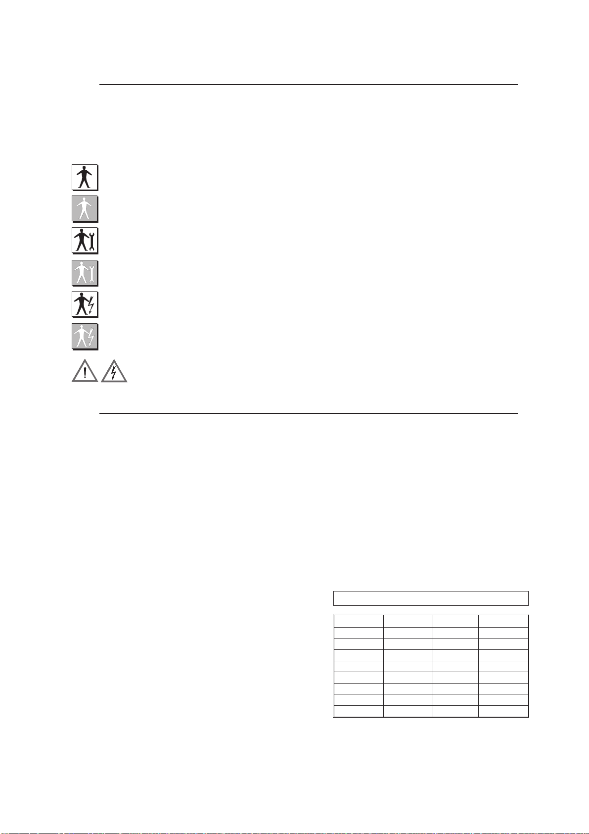
dangers and the necessity of technical support. Please find here below a list of symbols and relative meaning.
OPERATOR: Not particulary qualified staff, that can operate when no specific knowledge is required.
COEF OPERATOR Technical staff, qualified and trained by the constructor, for repair and extraordi-
nary operations.
MECHANICAL OPERATORS Staff employed in the ordinary mechanical maintenance.
SPECIALIZED MECHANICAL OPERATOR: Qualified staff employed in extraordinary authorized in-
stallations and repairs.
ELECTRIC OPERATORS: Staff employed in the ordinary electric maintenance.
SPECIALIZED ELECTRIC OPERATORS: Qualified staff employed in extraordinary authorized instal-
lations and repairs.
DANGER SIGNAL Generic danger signal and electric shock danger signal.
-
1.1 TECHNICAL NOTES
MP250 Zoom Code:ZL-012301-01
•
MSD 250/2 lamp - 250 W - 2.000 hours life - 8.000 °k
•
540° PAN - 270° TILT
•
16 bit movement resolution
•
PAN and TILT automatic repositioning
•
6 metal and 2 dichroich rotating gobos all interchangeable and indexable on 540°
•
10 additional metal gobos given with the projector
•
1 selectable beam reducer
•
10 colors + white + 8 bi-colors
•
Rainbow effect adjustable in speed
•
Black light filter
•
Linear dimmer from 0% to 100%
•
Mechanical shutter
•
Adjustable strobe
•
4 Lenses optical system
•
Linear zoom from 12° to 22°
•
Focus adjustment
•
Multifunctional display
•
Remote reset via DMX, selectable from display
•
Remote ON/OFF lamp via DMX, selectable from display
•
Software Upgrade via DMX (UNI-PROG 8 optional available)
•
Internal self-test with led indication
•
Internal power factor correction - absorbed power 1,4 A.
•
DMX 512 Standard
•
8/9 control channels
Power supply | Absorbed power
v~ Hz I W
100 50 4,3A 382
100 60 3,6A 361
120 50 3,6A 380
120 60 3,0A 359
200 50 2,2A 379
200 60 1,8A 359
230 50 1,7A 380
230 60 1,8A 385
Pag. 4 http://www.coef.it - info@coef.it
Page 5
2.0 INSTALLATION
The constructor is not to be considered responsible in the case of:
improper use of the unit or use by not trained staff
•
use in contrast with the directions on work safety
•
wrong installation
•
defective power supply
•
serious lacks in the necessary maintenance
•
unauthorized modifications and interventions
•
use of spare parts that are not original or not specific for the unit
•
total or partial inobservance of instructions
•
• Unusual events
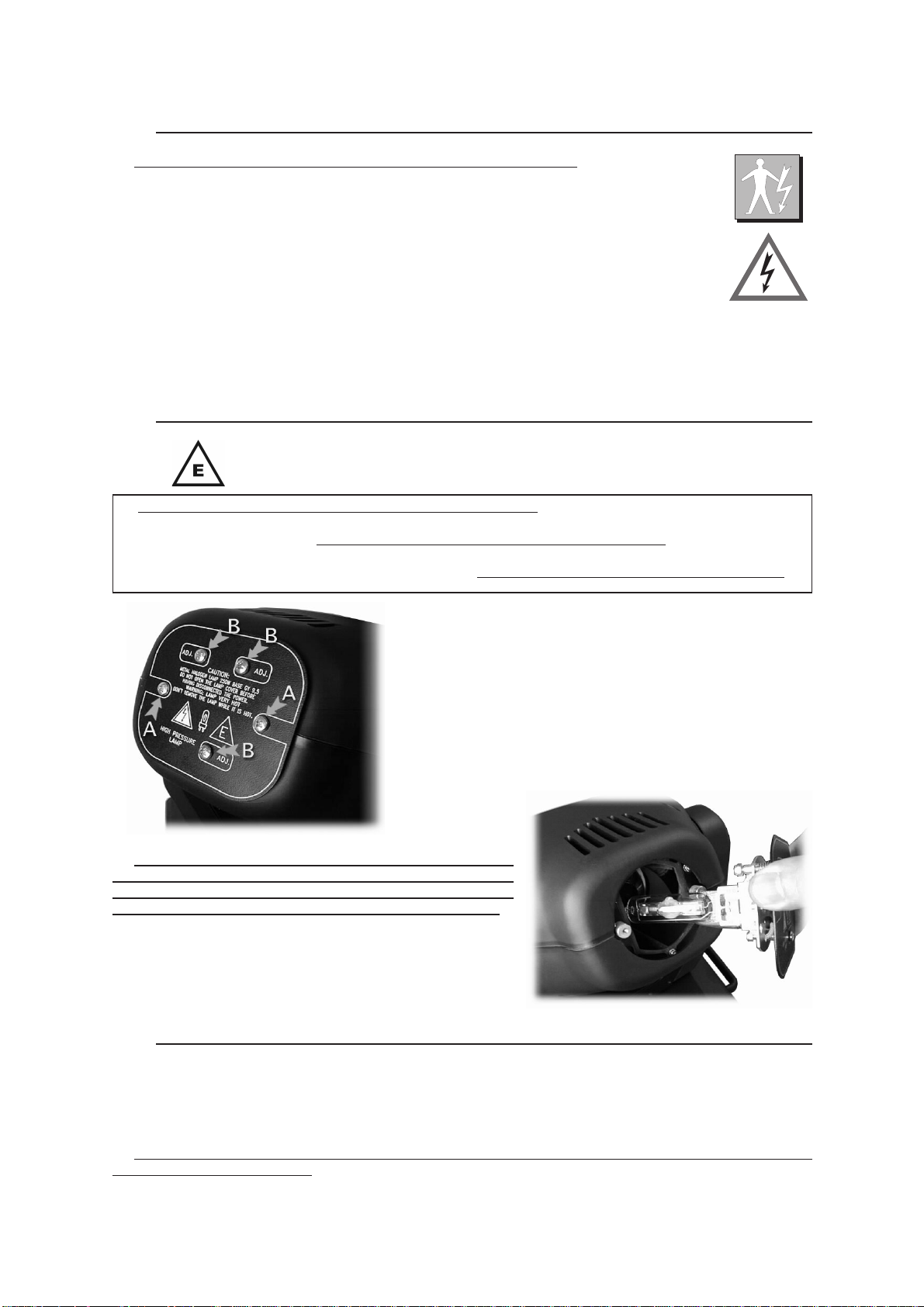
2.1 LAMP MOUNTING AND REPLACING
The unit mounts high pressure lamp with external traditional striker.
The lamp must be changed if damaged or deformed by heat.
WARNING: switch off the projector before operating.
Read carefully the lamp builder’s instructions.
Screw the two screws off (part.A) and remove the round cover
that’s supporting the lampholder. Insert the lamp (MSD250/2) in
the socket. Insert delicately the lamp inthe projector support, driving it with the round cover.
Pay attention: the lampholder’s wires must correctly reenter in
the projector. Block the cover screwing the screws up.
Wait at least 10 minutes after the projector has been
switched off before operating again, in order to let it cool
down and avoid the lamp explosion. Wait 20 minutes in case
you are operating with bare hands in order to avoid burns.
2.2 LAMP ADJUSTMENT
Lamp adjstment is necessary to obtain a uniform and powerful light beam. Switch on the projector and set the
shutter to open, set the color as white. Adjust the three screws (part. B) until you reach the ideal condition between
power and homogeneity.
WARNING! The lamp is pre-regulated by the factory. Only fine-adjustment is required. Don’t move the screws B
up to upper or lower extremities.
http://www.coef.it - info@coef.it Pag. 5
Page 6
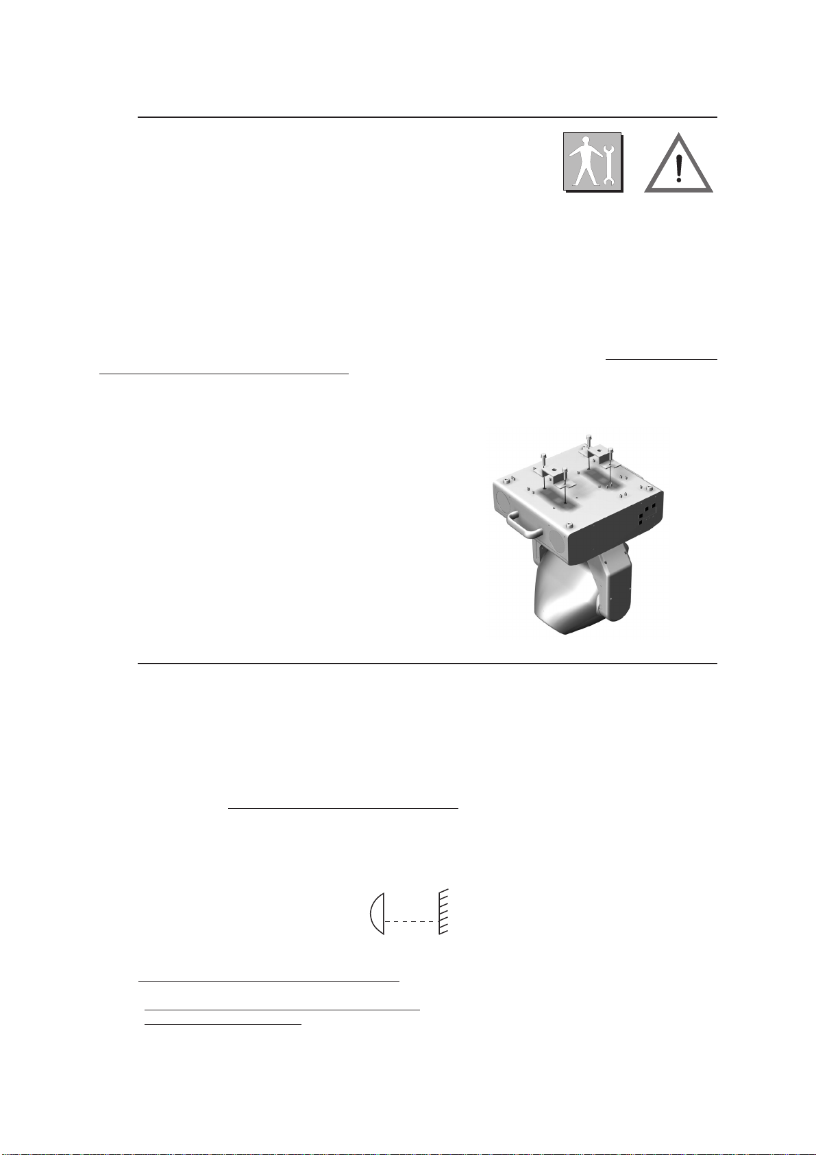
2.3 PROJECTOR INSTALLATION
To fix the MP250 Zoom is necessary, when the installation has to be on a raised-from-the ground support, to
block the fixing bracket of the unit by means of a screw provided with nut and locknut measuring not less than
M10X50, to insert in the central pre-arranged hole on the fixing bracket.
In order to guarantee a necessary security and in respect of the actual safety rules concerning the projectors’ installation, it is compulsory to install a safety-chain (or steel cable), equipped with spring clips, to connect the MP250
Zoom‘s body to the fixing structure.
ATTENTION: the safety-chain must be properly installed and fixed to the supporting structure, in a way that an
incidental giving in of the main bracket would leed to the shortest possible fall of the projector. After such an intervention the safety-chain must be replaced.
ATTENTION: COEF is not responsible for installations not correctly made or made without respecting the
above indications: those installations are considered dangerous.
2.4 ADVICES FOR A CORRECT INSTALLATION
The following conditions have to be respected for a correct operation:
1) Do not install the projector outside where the influence of atmospheric factors could damage the unit work-
ing (rain, wind, intense heat etc.).
2) Do not clean the projector using water jets or immersion in different liquids. Scrupulously follow the indica-
tions given in the chapter MAINTENANCE.
3) Make the electric connections and the installation / replacement of the lamp after haved disconnected the
power supply and after haved positioned the power switch to OFF
4) Do not touch in any case the internal and external parts of the projector without previous authorization of the
constructor and make modifications only by the intervention of qualified staff.
5) Make sure that the projector is correctly fixed on the support as indicated in par.2.3.
1,5 m
6) Minimum distance from illuminated objects:
struck by the light beam are located at least 1,5 metres from the projector objective.
7) Minimum distance from inflammable materials:
8) MAX ambient temperature:
40° C.
The projector must be positioned in such a way that objects
.
0.3 meters
Pag. 6 http://www.coef.it - info@coef.it
Page 7
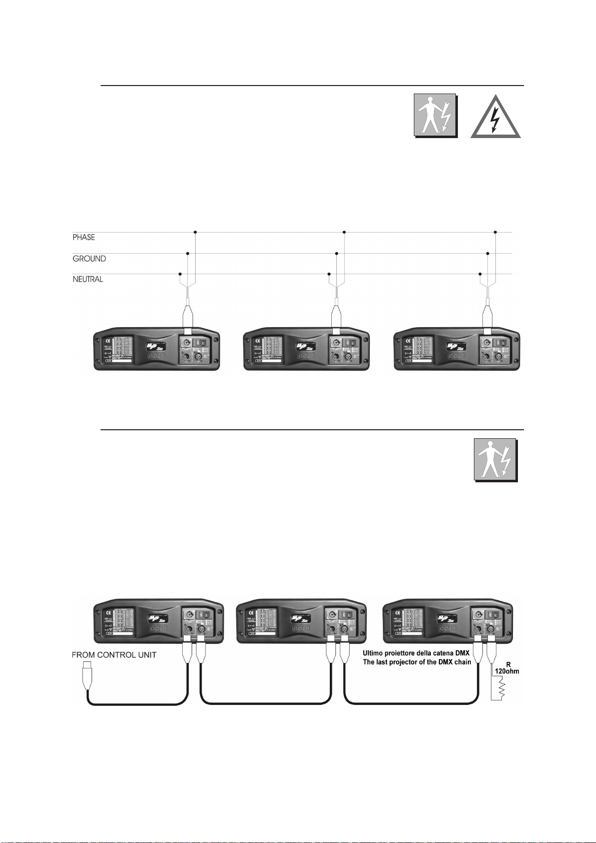
3.0 POWER SUPPLY CONNECTIONS
Supply the projector by connecting it as indicated in picture
Power supply: 100/120/200/230 V~ 50-60 Hz. Voltage and frequency as indicated on the rear of the projector.
Power absorbed: see table pag. 4
3.1 DMX 512 CONNECTIONS
Connect the projector to the control unit by means of a RG58 or RG59 coaxial cable supplied with 3 Pin XRL
Cannon plugs and connectors. Respect, according to the indications on the panel, the input and the output of the
DMX 512 signal.
http://www.coef.it - info@coef.it Pag. 7
Page 8
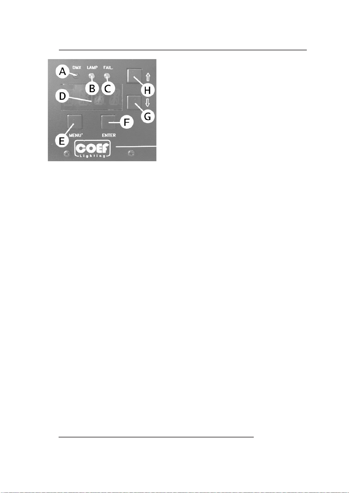
4.0 SPECIAL FUNCTIONS AND PROJECTOR ASSIGNMENT
On the front panel of MP250 Zoom you'll find a section for
the additional functions and for setting the projector.
Following the picture, you can see all the offered possibili
ties in detail.
All operations are to be carried out with the E, F, G, H buttons, respectively indicated as MENU, ENTER, DOWN and
UP.
The display D will inform you about the selected functions.
The 3 A, B, and C leds will allow you to know:
A = reception of the DMX line.
B = lamp ON.
C = errors indicated on the ERR table.
On switching the projector on, the display will indicate the type of projector and the version of control software
which have been installed. To this purpose, please remember that this type of projector belongs to a new generation
of projectors, designed with the possibility of updating the software version through the normal DMX connection by
means of a programmer deliberately created: UNI-PROG 8.
After the indication MSTR HOME, the projector carries out the RESET and gets ready to be controlled from the
connected console.
The display will indicate 1 as default value. This means that the first channel occupied by the projector will respond to the values sent to channel 1 by the DMX line. This also means that according to the total number of channels assigned to the projector by means of the CH89 function, MISC menu (see Table 4.1 Menu/Fuctions), we shall
be able to check the MP250 Zoom with the 1 to X channels (8 or 9 according to how the setting is) of the DMX line.
This enables us to make MP250 Zoom (which we are installing) completely independent from control or integral with
any other installed projector.
-
General Rules:
Refer to the Table of Section 4.1 in the following page.
By each pressure, Button MENU (E) permits to go backwards by one level.
GandH(DOWN and UP) buttons select functions and sub-functions.
Button F (ENTER) enters the function and confirms a control.
By pressing Button MENU (E) and buttons UP and DOWN (H and G) you can select the menu you have to modify.
Once the wished menu is reached, press Button F (ENTER) to confirm your selection and enter the function.
Press G or H to enter the sub-functions if available.
Always confirm your selection with ENTER.
Press MENU to go out of the function and press again to go back to the starting level.
Example: We installed our projector on the ceiling and for this reason we want the visualization of the display to
be correct.
•
Press MENU
•
Press H (UP) 11 times up to “MISC”
•
Press ENTER the Display will show “RSET”
•
Press H (UP) twice up to “DSPL”
•
Press ENTER the Display will show “ONOF”
•
Press H (UP) once up to “STRV”
•
Press ENTER the Display will show “STND”; this is the actual configuration state.
•
Press H (UP) once up to R.E.V..; the blinking point indicate the available configuration.
•
Press ENTER ...... The Display visualization as been rotated to 180°.
•
Press MENU 4 times to return to starting MENU.
The indication of the display will automatically come back after 120 sec. and inform on the set starting channel
DMX. If we are now in a sub-function, this automatic device will not assume control.
Pag. 8 http://www.coef.it - info@coef.it
Page 9
4.1 MENU, FUNCTION & SUB-FUNCTION
MENU FUNCTION SUB-FUNCTION DESCRIPTION
DMX (*) 1 / 255 DMX start channel
TIME
ERR
SHUT
COL
GOBO
LAMP
MACH
EOK
E110
E210
E220
E230
E240
E250
E260
E510
E260
W310
W410
HOME
TEST
HOME
TEST
CSHUT
MODE
HOME
TEST
GSHUT (*) OFF / ON
SHOW - KH, H
RESET - GO?
SHOW - KH, H
(*) OFF / ON
(*) MOD1 / MOD2
Lamp working hours (KH=thousands H=hours)
Lamp working hours reset (confirm by ENTER)
Projector working hours (KH=thousands H=hours)
NO ERROR
EEPROM failure
Malfunction of the SHUTTER motor
Malfunction of the COLOR motor/sensor
Malfunction of the GOBOS motor/sensor
Malfunction of the GOBOS ROT. motor/sensor
Malfunction of the PAN motor/sensor
Malfunction of the TILT motor/sensor
Malfunction of the PAN Encoder
Malfunction of the TILT Encoder
Checksum Setup not valid
Lamp working hours for more than 1900 hours.
HOME SHUTTER
TEST SHUTTER
HOME COLOR
TEST COLOR
Color change in black-out position
Color switching or linear wheel motion.
HOME GOBOS
TEST GOBOS
GOBO change in black-out position
RGOB
PAN
TILT
SCH da CH1 a CH9 0 / 255 DMX value for the indicated channel
LAMP
MISC
HOME
TEST
HOME
TEST
STRV
ENCO
HOME
TEST
STRV
ENCO
ONOF
CDMX
RSET
RDMX
DSPL
SWPT
CH 8/9
VER
(*) STND / REV
(*) ON / OFF
(*) STND / REV
(*) ON / OFF
ON
OFF
AUTO
(*) NO / YES
(*) YES / NO
(*) ON / OFF
(*) STND / REV
(*) STND / SWAP
(*)CH8/CH9
HOME GOBOS rotation
TEST GOBOS rotation
HOME PAN movement
TEST PAN movement
Switch movement direction ( DX / SX)
ON/OFF the automatic repositioning of the PAN
HOME TILT movement
TEST TILT movement
Switch movement direction (UP / DOWN)
ON/OFF the automatic repositioning of the TILT
LAMP ON
LAMP OFF
LAMP OFF after 1 hour of no change on DMX
LAMP switching on by DMX control
MASTER HOME (Starting RESET)
MASTER HOME via DMX control
Display on / Display off
180° rotation of the visualization display
Channel control switch PAN / TILT
Pojector control (8 or 9 channels)
Show the installed software version
(*) default value- factory assigned
http://www.coef.it - info@coef.it Pag. 9
Page 10
5.0 CHANNELS AND DIGITAL VALUES
CH
1
2
MODE1
8 CHANNELS 9 CHANNELS
SHUTTER / STROBE / DIMMER
0-5 SHUTTER closed
6-100 DIMMER Adjustment
101-110 DIMMER 0 > 100% Automatic 6 sec.
111-120 DIMMER 100% > 0 Automatic 6 sec.
121-126 DIMMER 0 > 100% slow Faster shut down
127-132 DIMMER 0 > 100% middle Faster shut down
133-138 DIMMER 0 > 100% fast Faster shut down
139-144 DIMMER 100% > 0 slow Faster open
145-150 DIMMER 100% > 0 middle Faster open
151-156 DIMMER 100% > 0 fast Faster open
157-162 Dimmer 0 > 100% > 0 slow
163-168 Dimmer 0 > 100% > 0 middle
169-174 Dimmer 0 > 100% > 0 fast
175-180 Strobe lamp from 1 to 6 random [reg. 0.0-0.5 sec.]
181-186 Strobe lamp from 1 to 6 random [reg. 0.6-1.5 sec.]
187-192 Strobe lamp from 1 to 6 random [reg. 1.6-2.5 sec.]
193-250 STROBE Speed adjustment
251-255 SHUTTER open
COLOR MODE 1
0 - 5 Neutral
6 - 15 Yellow
16 - 25 Blue
26 - 35 Magenta
36 - 45 Green light
46 - 55 Orange
56 - 65 Cyano
66 - 75 Pink
76 - 85 Red
86 - 95 Blu light
96 - 105 Green
106 - 115 Wood
116 - 125 White-Yellow
126 - 135 Yellow-Blue
136 - 145 Blue-Magenta
146 - 155 Green light-Orange
156 - 165 Orange-Cyano
166 - 175 Cyano-Pink
176 - 185 Red-Blue light
186 - 195 Blue light-Green
196 - 200 Random full-color (slow)
201 - 205 Random full-color (fast)
206 - 230 CW Rotation adjustment
231 - 255 CCW Rotation adjustment
SHUTTER / STROBE / DIMMER
0-5 SHUTTER closed
6-100 DIMMER from channel 9 value
101-110 DIMMER 0 > 100% Automatic 6 sec.
111-120 DIMMER 100% > 0 Automatic 6 sec.
121-126 DIMMER 0 > 100% slow Faster shut down
127-132 DIMMER 0 > 100% middle Faster shut down
133-138 DIMMER 0 > 100% fast Faster shut down
139-144 DIMMER 100% > 0 slow Faster open
145-150 DIMMER 100% > 0 middle Faster open
151-156 DIMMER 100% > 0 fast Faster open
157-162 Dimmer 0 > 100% > 0 slow
163-168 Dimmer 0 > 100% > 0 middle
169-174 Dimmer 0 > 100% > 0 fast
175-180 Strobe lamp from 1 to 6 random [reg. 0.0-0.5 sec.]
181-186 Strobe lamp from 1 to 6 random [reg. 0.6-1.5 sec.]
187-192 Strobe lamp from 1 to 6 random [reg. 1.6-2.5 sec.]
193-250 STROBE Speed adjustment
251-255 SHUTTER open
COLOR MODE 1
0 - 5 Neutral
6 - 15 Yellow
16 - 25 Blue
26 - 35 Magenta
36 - 45 Green light
46 - 55 Orange
56 - 65 Cyano
66 - 75 Pink
76 - 85 Red
86 - 95 Blu light
96 - 105 Green
106 - 115 Wood
116 - 125 White-Yellow
126 - 135 Yellow-Blue
136 - 145 Blue-Magenta
146 - 155 Green light-Orange
156 - 165 Orange-Cyano
166 - 175 Cyano-Pink
176 - 185 Red-Blue light
186 - 195 Blue light-Green
196 - 200 Random full-color (slow)
201 - 205 Random full-color (fast)
206 - 230 CW Rotation adjustment
231 - 255 CCW Rotation adjustment
2
MODE2
COLOR MODE 2
0 - 5 Neutral
6 - 10 Yellow
11 - 15 Blue
16 - 20 Magenta
21 - 25 Green light
26 - 30 Orange
31 - 35 Cyano
36 - 40 Pink
41 - 45 Red
46 - 50 Blu light
51 - 55 Green
56 - 60 Wood
61 - 180 Positioning
181 - 185 Random fast
186 - 190 Random middle
191 - 195 Random slow
196 - 200 Random very slow
201 - 215 Random very fast
216 - 235 CW Rotation adjustment
236 - 255 CCW Rotation adjustment
Pag. 10 http://www.coef.it - info@coef.it
Page 11
8 CHANNELS 9 CHANNELS
CH
GOBOS
0 - 10 Neutral
11 - 20 GOBO 1 chann.4 controls rotation
21 - 30 GOBO 2 chann.4 controls rotation
31 - 40 GOBO 3 chann.4 controls rotation
41 - 50 GOBO 4 chann.4 controls rotation
51 - 60 Reduction
61 - 70 GOBO 5 chann.4 controls rotation
71 - 80 GOBO 6 chann.4 controls rotation
81 - 90 GOBO 7 chann.4 controls rotation
91 - 100 GOBO 8 chann.4 controls rotation
3
101 - 110 GOBO 1 chann.4 controls position
111 - 120 GOBO 2 chann.4 controls position
121 - 130 GOBO 3 chann.4 controls position
131 - 140 GOBO 4 chann.4 controls position
141 - 150 GOBO 5 chann.4 controls position
151 - 160 GOBO 6 chann.4 controls position
161 - 170 GOBO 7 chann.4 controls position
171 - 180 GOBO 8 chann.4 controls position
181 - 193 GOBOS Fast random
194 - 205 GOBOS Slow random
206 - 230 CW Rotation adjustment
231 - 255 CCW Rotation adjustment
GOBOS ROTATION
0 - 5 STOP
6 - 255 From 0 to 540° GOBO positioning
4
6 - 130 CW Rotation adjustment of the GOBO
131 - 255 CCW Rotation adjustment of the GOBO
PAN MOVEMENT
5
PAN MOVEMENT FINE ADJUSTMENT
6
TILT MOVEMENT
7
TILT MOVEMENT FINE ADJUSTMENT
8
9
GOBOS
0 - 10 Neutral
1 1- 20 GOBO 1 chann.4 controls rotation
21 - 30 GOBO 2 chann.4 controls rotation
31 - 40 GOBO 3 chann.4 controls rotation
41 - 50 GOBO 4 chann.4 controls rotation
51 - 60 Reduction
61 - 70 GOBO 5 chann.4 controls rotation
71 - 80 GOBO 6 chann.4 controls rotation
81 - 90 GOBO 7 chann.4 controls rotation
91 - 100 GOBO 8 chann.4 controls rotation
101 - 110 GOBO 1 chann.4 controls position
111 - 120 GOBO 2 chann.4 controls position
121 - 130 GOBO 3 chann.4 controls position
131 - 140 GOBO 4 chann.4 controls position
141 - 150 GOBO 5 chann.4 controls position
151 - 160 GOBO 6 chann.4 controls position
161 - 170 GOBO 7 chann.4 controls position
171 - 180 GOBO 8 chann.4 controls position
181 - 193 GOBOS Fast random
194 - 205 GOBOS Slow random
206 - 230 CW Rotation adjustment
231 - 255 CCW Rotation adjustment
GOBOS ROTATION
0 - 5 STOP
6 - 255 From 0 to 540° GOBO positioning
6 - 130 CW Rotation adjustment of the GOBO
131 - 255 CCW Rotation adjustment of the GOBO
PAN MOVEMENT
PAN MOVEMENT FINE ADJUSTMENT
TILT MOVEMENT
TILT MOVEMENT FINE ADJUSTMENT
DIMMER
0 - 10 DIMMER CLOSED
11 - 250 DIMMER Adjustment
251 - 255 DIMMER OPEN
WARNING :position CHANNEL 1 at a value between 6 and100,
in order to control DIMMER with this channel.
SPECIAL ACTION
When the lamp control via DMX (CDMX) and the RDMX function have been activated in the configuration menu, it’s possible,
by a combination of the channels values, to control the lamp switch ON/OFF or to allow the projector MASTER RESET.
Lamp ON via DMX:
CHANNEL 2 = value 0
CHANNEL 3 and CHANNEL 4 = value0>255>0
Lamp OFF via DMX:
CHANNEL 2 = value 255
CHANNEL 3 and CHANNEL 4 = value0>255>0
MASTER RESET:
CHANNEL 1 = value 0
CHANNEL 2 and CHANNEL 3 = value0>255>0
http://www.coef.it - info@coef.it Pag. 11
Page 12
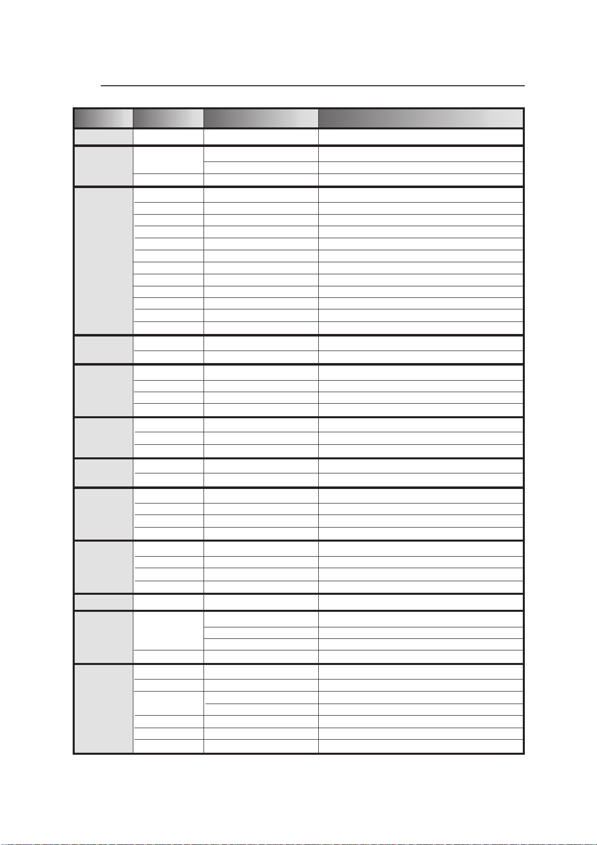
6.0 FOCUS ADJUSTMENT
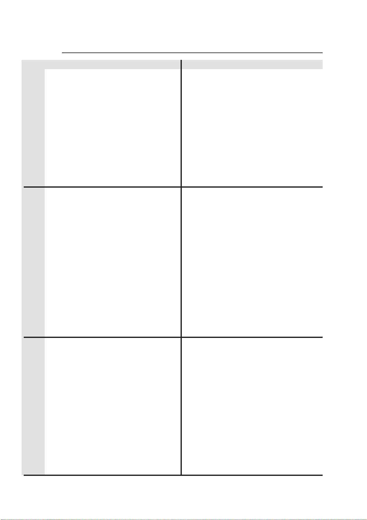
7.0 ZOOM ADJUSTMENT
12°
The width of the light beam of the MP250 Zoom is adjustable between 12° and 21° by means of the knob located
on the front part of the projector and indicated with the writing ZOOM.
Position your projector and adjust this knob in order to obtain the desired beam width.
Do not force your adjustment beyond the upper and lower limits of the available stroke.
21°
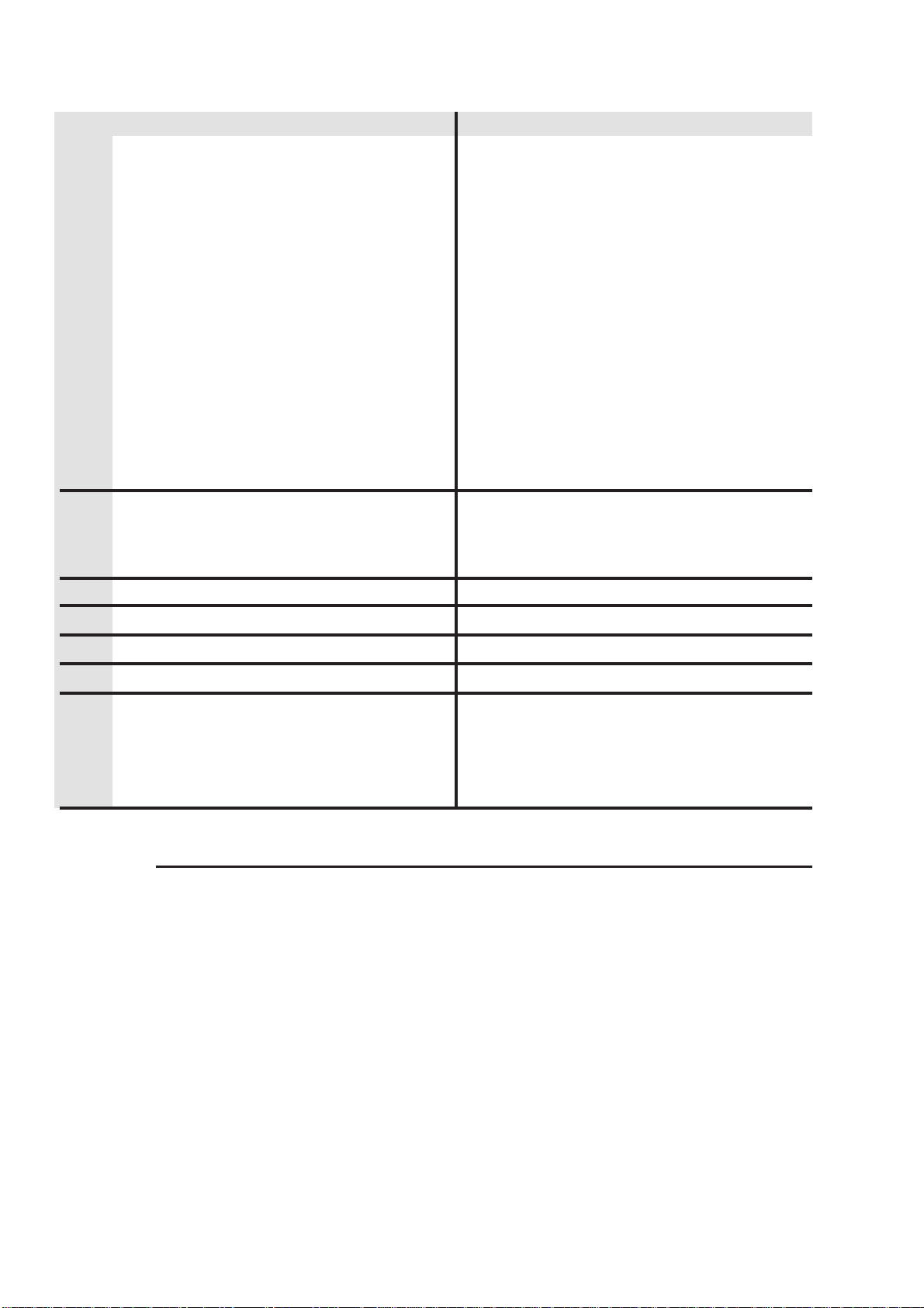
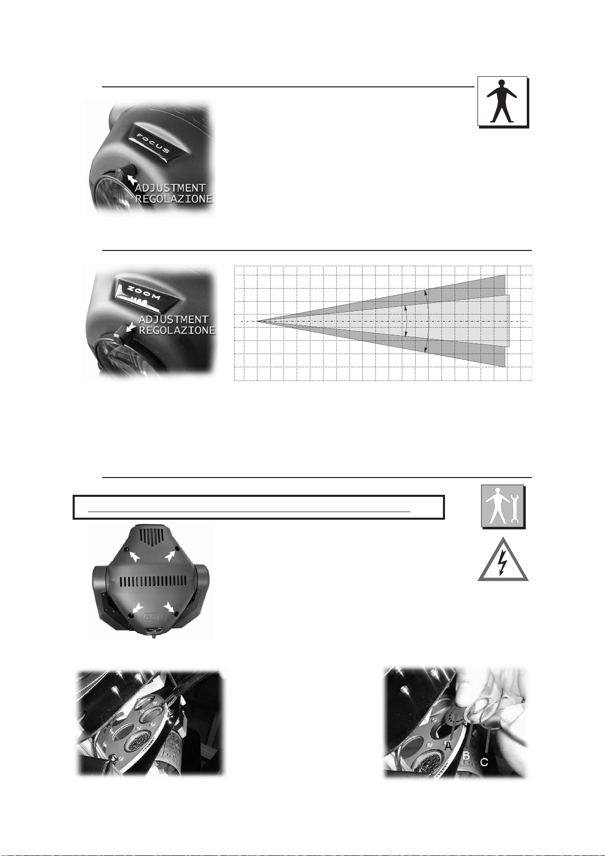
8.0 GOBOS REPLACEMENT
WARNING: switch off the projector before operating
Open the cover of the MP250 Zoom first, by means of
the 4 release-screws which hold it to the frame.
The gobo-wheel contains both steel gobos and dichroic gobos. They
are interchangeable simply by removing the little elastic ring with a screwdriver (see figure).
In order to replace a dichroic gobo with a steel gobo, put a thick ring be-
tween the gobo and the elastic ring (see part. B).
Insert the chosen gobo and place again the steel ring, paying attention
that it reaches its correct position.
Pag. 12 http://www.coef.it - info@coef.it
Page 13

9.0 ORDINARY MAINTENANCE
The ordinary maintenance is fundamental for the perfect efficiency of MP250 Zoom, in order to
prevent any functional defect as a reduced light beam or irregularities in the movement of the projector or of other rotating parts.
The parts which need more maintenance are shown in the figures. In order to free them from
dust or grease, clean them with a soft cloth and normal products for windows cleaning.
9.1 EXTRAORDINARY MAINTENANCE
To make an extraordinary maintenance, it is necessary the presence of a generic or qualified me-
chanical operator, according to the type of the needed intervention.To let you operate more easily,
we advice you to remove the two top covers of MP250 Zoom and the two basis covers. In this way it
will be much more easy to observe the components to maintain and/or replace. In the following figures it’s possible to observe the different parts that have to be cleaned and, at the same time, the
whole mechanical structure mounted with all its components is shown.
You must particularly take care of the sensors which are really funda-
mental in the unit working.
The sensors are absolutely necessary when a general reset of the projector is needed. If this function is not correctly executed, it will totally compromise the regular working of the projector, at least for the group referred
to the sensor itself.
Es : when there’s an irregular reset of the color wheel, all the setted colors will not correspond to the colours listed in the chapter about DMX digital
values.
The same situation will occur in the case of the gobos wheel .
The section shutter/strobo doesn’t use sensors during the reset position
ing but it’s conditioned by a mechanical beat of the shutter shovels.
http://www.coef.it - info@coef.it Pag. 13
-
Page 14

9.2 ELECTRONIC MAINTENANCE
This section is dedicated in detail to the electronic connections between the card and the mechanical compo
nents, assembled in the projector. These informations will be absolutely necessary when the mechanical unit has to
be removed from the projector for maintenance and/or repair.
The connections are made using handy connectors and are detailed where you can find indications about the
connection between a specific connector and a specific component of the mechanical unit. This includes the motors
and the sensors of the various effects wheels ( color, gobos, shutter etc.).
WARNING!
irremediably the electronic and/or mechanical components of the projector.
An improper use of this documentation made by not specifically qualified staff can damage
-
Pag. 14 http://www.coef.it - info@coef.it
Page 15

10.0 TROUBLESHOOTING
PROBLEM CAUSE ACTION
The projector doesn’t switch on
The projector switches on but
doesn’t answer to commands
Defecting projection
Projection with halo
- The power supply is not present
- The lamp is not working
- Wrong DMX configuration
- Defective cables
- Defective control unit
- The lens is broken
- Dust or grease stored on lenses
- Not aligned Lamp
- Dust or grease stored on the all
parts of projector.
Check if the luminous indicator is lighted
or not.
Replace the lamp.
Make sure that the projector is correctly
configurated.
Replace or repair the DMX cable.
Chek the control unit by means of other
working projectors.
Technical aid is required.
Ceck that the lens are not broken.
Remove dust or grease stored on lenses.
Lamp adjustment (see 2.2 chapter)
Carefully clean the optical group lenses
and the projector components (see “Maintenance” chapter)
The color or other effects doesn’t
coincide to the selected value.
The PAN movement doesn’t coincide to the selected value
The projector does not carry out
the automatic repositioning of the
PAN or TILT movements.
- Position sensor dirty with dust or
grease
- Defective Motor
- Electronic board
- Position sensor dirty with dust or
grease
- Defective Motor
- Electronic board
- ENCO OFF in the PAN/TILT configuration menu
Carefully clean the optical group lenses
and the projector components (see “Maintenance” chapter)
Technical aid is required.
Carefully clean the optical group lenses
and the projector components (see “Maintenance” chapter)
Technical aid is required.
Set ON ENCO Function of PAN/TILT configuration MENU (cap. 4.1)
Technical aid is required.
http://www.coef.it - info@coef.it Pag. 15
Page 16

1.0 ELECTRIC DIAGRAM
11.0
14-08-2005
http://www.coef.it - info@coef.it Pag. 16
Page 17

13.0 DIMENSIONS
12.0
Pag. 17 http://www.coef.it - info@coef.it
Page 18

14.0 PART ASSEMBLY
13.0
http://www.coef.it - info@coef.it Pag. 18
Page 19

Pag.19 http://www.coef.it - info@coef.it
Page 20

Pag.19 http://www.coef.it - info@coef.it
Page 21

http://www.coef.it - info@coef.it Pag. 18
13.0
14.0 ASSEMBLAGGIO PARTI
Page 22

Pag. 17 http://www.coef.it - info@coef.it
12.0
13.0 DIMENSIONI
Page 23

http://www.coef.it - info@coef.it Pag. 16
11.0
14-08-2005
12.0 SCHEMA ELETTRICO
Page 24

Intervento di assistenza tecnica.
der ai canali del PAN e del TILT.
Vedi tabella cap. 4.1 per abilitare l’enco-
Intervento di assistenza tecnica
zione)
parti del proiettore (vedi capitolo manutenEffettuare una accurata pulizia di tutte le
Intervento di assistenza tecnica
zione)
parti del proiettore (vedi capitolo manutenEffettuare una accurata pulizia di tutte le
http://www.coef.it - info@coef.it Pag. 15
movimento PAN o TILT
e sottofunzione ENCO a OFF
- Configurazione menu PAN o TILT
- Scheda elettronica
- Motore difettoso
- Cinghia rotta
- Sensori di posizione sporchi
- Scheda elettronica
- Motore difettoso
- Cinghia rotta
- Sensori di posizione sporchi
sizionamento automatico per il
Il proiettore non esegue il ripo-
stati
TILT non segue i valori impoIl movimento del PAN o del
spondono al valore impostato
Il colore o altri effetti non corri-
zione)
parti del proiettore (vedi capitolo manutenEffettuare una accurata pulizia di tutte le
Regolare la lampada
ti.
Rimuovere la polvere e/o grasso sulle len-
Controllare che la lente non sia rotta.
Intervento di assistenza tecnica.
proiettori funzionanti.
Controllare l’unità di pilotaggio con altri
Sostituire i cavi o riparare.
Assegnare il valore DMX per il proiettore
la Lampada.
Vedi tabella cap. 4.1 per configurare in ON
Sostituire la lampada.
te le parti del proiettore
- Strati di grasso e/o polvere su tut-
- Posizione lampada non regolata
lenti
- Strati di grasso o polvere sulle
- La lente è rotta
- Unità di pilotaggio difettosa
- Cavi di collegamento difettosi
- Configurazione DMX errata
dal menu LAMP
- La lampada è configurata in OFF
- Lampada non funzionante
Proiezione con alone
Proiezione difettosa
sponde ai comandi
Il proiettore si accende ma non ri-
terruttore di accensione.
-
Verificare l’accensione della spia sull’in
- Mancanza di alimentazione di rete
DIFETTO CAUSA RIMEDIO
Il proiettore non si accende
10.0 PROBLEMI
Page 25

Pag. 14 http://www.coef.it - info@coef.it
eseguite delle operazioni di manutenzione straordinaria e/o riparazioni.
qualificato, può danneggiare in modo irrimediabile le parti elettroniche e/o meccaniche del proiettore su cui vengono
Un uso improprio di questa documentazione, od effettuato da personale non espressamente
ATTENZIONE!
pora i motori e i sensori delle ruote dei vari effetti ( colore, gobos, otturatore ecc. ).
spondenza di un determinato connettore ad una determinata parte componente della piastra meccanica, che incor-
I collegamenti effettuati attraverso comodi connettori vengono dettagliati nella figura dove è indicata la corri-
sa scheda elettronica, vengano rimosse dall’interno del proiettore per manutenzione e/o riparazione.
all’interno del proiettore. Questeinformazioni risultanoindispensabili nel caso in cui le piastre meccaniche, o la stes-
Questa sezione è dedicata al dettaglio dei collegamenti elettronici tra la scheda e le parti meccaniche montate
9.2 MANUTENZIONE ELETTRICA/ELETTRONICA
Page 26

http://www.coef.it - info@coef.it Pag. 13
mento.
-
-
di reset ma è condizionata da una battuta meccanica delle palette d’oscura
La sezione otturatore/strobo, non usa sensori per il posizionamento in fase
La stessa identica situazione si presenterà nel caso della ruota gobos.
to.
ai valori digitali daimpostare nelcanale DMX per ottenere il colore desidera
ranno non corrispondenti alle caratteristiche dichiarate nel capitolo dedicato
Es: ad un reset irregolare della ruota colore, tutti i colori impostati risulte-
il gruppo associato al sensore stesso.
il funzionamento regolare del proiettore stesso, almeno per quanto riguarda
tore, funzione che se non eseguita correttamente, pregiudica in modo totale
I sensori sono indispensabili nel momento del reset generale del proiet-
ruolo fondamentale nel funzionamento dell’apparecchiatura.
Una particolare attenzione andrà dedicata ai sensori che rivestono un
parti.
zia e nello stesso tempo potremo avere una vista d’insieme della meccanica montata con tutte le sue
nere e/o sostituire. Nelle figure a seguire è possibile osservare i vari punti indicati come punti di pulicopertura della base. In questo modo risulterà molto più semplice osservare le varie parti da manutevento consigliamo di rimuovere i due coperchi della testa del MP250 Zoom e le due piastre di
co semplice o di uno qualificato, a seconda del tipo di intervento da eseguire. Per semplicità di inter-
Per eseguire una manutenzione straordinaria è richiesto l’intervento di un manutentore meccani-
9.1 MANUTENZIONE STRAORDINARIA
alla loro pulizia con un panno morbido e normali prodotti per la pulizia dei vetri.
Nelle figure vengono evidenziate le parti più sottoposte ad accumulare polveri e grassi. Procedere
del fascio oppure il movimento irregolare del proiettore o di altre parti rotanti.
efficenza l’apparecchiatura ed evitare l’insorgere di difetti come ad esempio la scarsa resa luminosa
La manutenzione ordinaria sui proiettori MP250 Zoom è indispensabile per mantenere in perfetta
9.0 MANUTENZIONE ORDINARIA
Page 27

Pag. 12 http://www.coef.it - info@coef.it
do le 4 viti a scatto.
con il coperchio inferiore e serranrandosi del corretto allineamento
Rimontare il coperchio assicu-
ritorni nella sua gola predisposta.
(part. C) avendo cura che questo
to e rimettere l’anello di acciaio
Inserire il nuovo gobo prescel-
prima dell’anello elastico (vedi part. B).
uno di acciaio, quest’ultimo deve avere un anello di spessore da inserire
fine (vedi figura). Per permettere la sostituzione di un gobo dicroico con
muovendo l’anello elastico in acciaio con l’aiuto di un cacciavite a taglio
bos dicroici. I due tipi di gobos risultano intercambiabili semplicemente ri-
La ruota gobos dell’ MP250 Zoom contiene sia gobos in acciaio che go-
laio.
Zoom per mezzo delle 4 viti a scatto che lo bloccano al te-
Per prima cosa occorre aprire il coperchio dell’ MP250
21°
ATTENZIONE: Disconnettere l’apparecchio dalla rete prima di questo intervento
8.0 SOSTITUZIONE GOBOS
Non forzare la regolazione oltre i limiti inferiore e superiore della corsa disponibile.
esigenza.
Posizionate il proiettore e regolate questa manopola per ottenere l’ampiezza del fascio a seconda della vostra
nata sul fronte del proiettore ed indicata dalla scritta ZOOM.
L’ampiezza del fascio luminoso dell’MP250 Zoom è regolabile tra 12° e 21° per mezzo della manopola posizio-
12°
7.0 REGOLAZIONE ZOOM
posizionando il proiettore dove desiderato.
dalla scritta FOCUS (vedi figura) e regolare la messa a fuoco dell’obiettivo,
Ruotare la manopola presente sul fronte del proiettore ed evidenziata
re aperto l’otturatore, assegnare il colore bianco e inserire un gobo a scelta.
-
Per regolare l’obiettivo occorre predisporre i canali in modo tale da ave
6.0 REGOLAZIONE DEL FUOCO
Page 28

nale.
preso tra 6 e 100 per controllare il DIMMER con questo caATTENZIONE: posizionare il CANALE 1 ad un valore com-
http://www.coef.it - info@coef.it Pag. 11
CANALE 2 e CANALE 3 = Valore0>255>0
CANALE 1 = Valore 0
MASTER RESET:
CANALE 3 e CANALE 4 = Valore0>255>0
CANALE 2 = Valore 255
Spegnimento della lampada via DMX:
CANALE 3 e CANALE 4 = Valore0>255>0
CANALE 2 = Valore 0
Accensione della lampada via DMX:
MASTER RESET al proiettore.
verso una combinazione di valori nei canali, controllare sia l’accensione e lo spegnimento della lampada oppure far eseguire un
Se nel MENU configurazioniè statoabilitato il controllo della lampada via DMX (CDMX) e la funzione RDMX, è possibile, attra-
COMANDI SPECIALI
251 - 255 DIMMER Aperto
11 - 250 Regolazione DIMMER
0 - 10 DIMMER Chiuso
DIMMER
REGOLAZIONE FINE MOVIMENTO TILT
MOVIMENTO TILT
REGOLAZIONE FINE MOVIMENTO PAN
MOVIMENTO PAN
131 - 255 Reg. Rotazione anti-oraria per GOBO in rotaz.
6 - 130 Reg. Rotazione oraria per GOBO in rotaz.
6 - 255 Da 0 a 540° per GOBO posizionabile
0 - 5 STOP
ROTAZIONE GOBOS
231 - 255 Rotazione in senso anti-orario regolabile
206 - 230 Rotazione in senso orario regolabile
194 - 205 GOBOS Random lento
181 - 193 GOBOS Random veloce
171 - 180 GOBO 8 can.4 regola il posizionamento
161 - 170 GOBO 7 can.4 regola il posizionamento
151 - 160 GOBO 6 can.4 regola il posizionamento
141 - 150 GOBO 5 can.4 regola il posizionamento
131 - 140 GOBO 4 can.4 regola il posizionamento
121 - 130 GOBO 3 can.4 regola il posizionamento
111 - 120 GOBO 2 can.4 regola il posizionamento
101 - 110 GOBO 1 can.4 regola il posizionamento
91 - 100 GOBO 8 can.4 regola la rotazione
81 - 90 GOBO 7 can.4 regola la rotazione
71 - 80 GOBO 6 can.4 regola la rotazione
61 - 70 GOBO 5 can.4 regola la rotazione
51 - 60 RIDUTTORE
41 - 50 GOBO 4 can.4 regola la rotazione
31 - 40 GOBO 3 can.4 regola la rotazione
21 - 30 GOBO 2 can.4 regola la rotazione
1 1- 20 GOBO 1 can.4 regola la rotazione
0 - 10 Neutro
GOBOS
9
REGOLAZIONE FINE MOVIMENTO TILT
8
MOVIMENTO TIL
7
REGOLAZIONE FINE MOVIMENTO PAN
6
MOVIMENTO PAN
5
131 - 255 Reg. Rotazione anti-oraria per GOBO in rotaz.
6 - 130 Reg. Rotazione oraria per GOBO in rotaz.
6 - 255 Da 0 a 540° per GOBO posizionabile
4
0 - 5 STOP
ROTAZIONE GOBOS
231 - 255 Rotazione in senso anti-orario regolabile
206 - 230 Rotazione in senso orario regolabile
194 - 205 GOBOS Random lento
181 - 193 GOBOS Random veloce
171 - 180 GOBO 8 can.4 regola il posizionamento
161 - 170 GOBO 7 can.4 regola il posizionamento
151 - 160 GOBO 6 can.4 regola il posizionamento
141 - 150 GOBO 5 can.4 regola il posizionamento
131 - 140 GOBO 4 can.4 regola il posizionamento
121 - 130 GOBO 3 can.4 regola il posizionamento
111 - 120 GOBO 2 can.4 regola il posizionamento
3
101 - 110 GOBO 1 can.4 regola il posizionamento
91 - 100 GOBO 8 can.4 regola la rotazione
81 - 90 GOBO 7 can.4 regola la rotazione
71 - 80 GOBO 6 can.4 regola la rotazione
61 - 70 GOBO 5 can.4 regola la rotazione
51 - 60 RIDUTTORE
41 - 50 GOBO 4 can.4 regola la rotazione
31 - 40 GOBO 3 can.4 regola la rotazione
21 - 30 GOBO 2 can.4 regola la rotazione
1 1- 20 GOBO 1 can.4 regola la rotazione
0 - 10 Neutro
GOBOS
CH
8 CANALI 9 CANALI
Page 29

Pag. 10 http://www.coef.it - info@coef.it
236 - 255 Rotazione in senso anti-orario regolabile
216 - 235 Rotazione in senso orario regolabile
201 - 215 Casuale colori pieni (velocissimo)
196 - 200 Casuale colori pieni (lentissimo)
191 - 195 Casuale colori pieni (lento)
186 - 190 Casuale colori pieni (medio)
181 - 185 Casuale colori pieni (veloce)
61 - 180 Posizionamento
56 - 60 Wood
51 - 55 Verde chiaro
46 - 50 Blu chiaro
41 - 45 Rosso
36 - 40 Rosa
31 - 35 Celeste
26 - 30 Arancio
21 - 25 Verde chiaro
16 - 20 Magenta
11 - 15 Blu scuro
6 - 10 Giallo
0 - 5 Neutro
COLORE MODE 2
231 - 255 Rotazione in senso anti-orario regolabile
206 - 230 Rotazione in senso orario regolabile
201 - 205 Casuale colori pieni (veloce)
196 - 200 Casuale colori pieni (lento)
186 - 195 Bicolore Blu chiaro-Verde scuro
176 - 185 Bicolore Rosso-Blu chiaro
166 - 175 Bicolore Celeste-Rosa
156 - 165 Bicolore Arancio-Celeste
146 - 155 Bicolore Verde chiaro-Arancio
136 - 145 Bicolore Blu scuro-Magenta
126 - 135 Bicolore Giallo-Blu scuro
116 - 125 Bicolore Bianco-Giallo
106 - 115 Wood
96 - 105 Verde scuro
86 - 95 Blu chiaro
76 - 85 Rosso
66 - 75 Rosa
56 - 65 Celeste
46 - 55 Arancio
36 - 45 Verde chiaro
26 - 35 Magenta
16 - 25 Blu scuro
6 - 15 Giallo
0 - 5 Neutro
COLORE MODE 1
2
MODE
2
1
MODE
2
251-255 OTTURATORE aperto
193-250 Regolazione velocità STROBO
187-192 Lampi da1a6random [reg. 1.6-2.5 sec.]
181-186 Lampi da1a6random [reg. 0.6-1.5 sec.]
175-180 Lampi da1a6random [reg. 0.0-0.5 sec.]
169-174 Dimmer 0 > 100% > 0 veloce
163-168 Dimmer 0 > 100% > 0 medio
157-162 Dimmer 0 > 100% > 0 lento
151-156 DIMMER 100% > 0 veloce Apertura istantanea
145-150 DIMMER 100% > 0 medio Apertura istantanea
139-144 DIMMER 100% > 0 lento Apertura istantanea
133-138 DIMMER 0 > 100% veloce Chiusura istantanea
127-132 DIMMER 0 > 100% medio Chiusura istantanea
121-126 DIMMER 0 > 100% lento Chiusura istantanea
111-120 DIMMER 100% > 0 Automatico in 6 sec.
101-110 DIMMER 0 > 100% Automatico in 6 sec.
6-100 DIMMER con valore impostato canale 9
0-5 OTTURATORE chiuso
OTTURATORE / STROBO / DIMMER
8 CANALI 9 CANALI
251-255 OTTURATORE aperto
193-250 Regolazione velocità STROBO
187-192 Lampi da1a6random [reg. 1.6-2.5 sec.]
181-186 Lampi da1a6random [reg. 0.6-1.5 sec.]
175-180 Lampi da1a6random [reg. 0.0-0.5 sec.]
169-174 Dimmer 0 > 100% > 0 veloce
163-168 Dimmer 0 > 100% > 0 medio
157-162 Dimmer 0 > 100% > 0 lento
151-156 DIMMER 100% > 0 veloce Apertura istantanea
145-150 DIMMER 100% > 0 medio Apertura istantanea
139-144 DIMMER 100% > 0 lento Apertura istantanea
1
133-138 DIMMER 0 > 100% veloce Chiusura istantanea
127-132 DIMMER 0 > 100% medio Chiusura istantanea
121-126 DIMMER 0 > 100% lento Chiusura istantanea
111-120 DIMMER 100% > 0 Automatico in 6 sec.
101-110 DIMMER 0 > 100% Automatico in 6 sec.
6-100 Regolazione DIMMER
0-5 OTTURATORE chiuso
OTTURATORE / STROBO / DIMMER
CH
5.0 CANALI E VALORI DIGITALI
Page 30

http://www.coef.it - info@coef.it Pag. 9
(*) = valori impostati di default in fabbrica
Mostra la versione del software installato.
Controllo proirttorea8o9canali
Scambia i canali attribuiti a PAN e TILT
Inverte di 180° la visualizzazione del Display
Display visibile / Display spento
Abilita MASTER HOME via DMX
Esegue il MASTER HOME (RESET INIZIALE)
Controllo accensione della lampada via DMX
Lampada spenta dopo 1 ora di inattività DMX
Lampada spenta
Lampada accesa
Consente o esclude il riposizionamento automatico
Cambia la direzione di movimento (Alto / Basso)
Esegue il test movimento TILT
Esegue HOME movimento TILT
Consente o esclude il riposizionamento automatico
Cambia la direzione di movimento ( DX / SX)
Esegue il test movimento PAN
Esegue HOME movimento PAN
Esegue il test Rotazione GOBOS
Esegue HOME Rotazione GOBOS
(*)CH8/CH9
(*) STND / SWAP
(*) STND / REV
(*) ON / OFF
(*) YES / NO
(*) NO / YES
AUTO
OFF
ON
(*) ON / OFF
(*) STND / REV
(*) ON / OFF
(*) STND / REV
VER
CH 8/9
SWPT
DSPL
RDMX
RSET
CDMX
ONOF
ENCO
STRV
TEST
HOME
ENCO
STRV
TEST
HOME
TEST
HOME
MISC
LAMP
SCH da CH1 a CH9 0 / 255 Visualizza il valore DMX sul canale prescelto
TILT
PAN
RGOB
Cambio gobo con otturatore chiuso al cambio
Esegue il test GOBOS
Esegue HOME GOBOS
Commutazione del colore o movimento lineare
Cambio colore con otturatore chiuso al cambio
Esegue il test COLORE
Esegue HOME COLORE
Esegue il test OTTURATORE
Esegue HOME OTTURATORE
Accensione della lampada oltre le 1900 ore
Checksum Setup non valido
Malfunzionamento Encoder TILT
Malfunzionamento Encoder PAN
Malfunzionamento motore/sensore TILT
Malfunzionamento motore/sensore PAN
Malfunzionamento motore/sensore Rot.GOBOS
Malfunzionamento motore/sensore GOBOS
Malfunzionamento motore/sensore COLORE
Malfunzionamento motore OTTURATORE
EEPROM guasta
Nessun errore
Ore di funzionamento della macchina (migliaia e ore)
Resetta le ore della lampada (conferma con ENTER)
Ore di funzionamento della lampada (migliaia e ore)
(*) MOD1 / MOD2
(*) OFF / ON
SHOW - KH, H
RESET - GO?
SHOW - KH, H
GSHUT (*) OFF / ON
TEST
HOME
MODE
CSHUT
TEST
HOME
TEST
HOME
W410
W310
E520
E510
E260
E250
E240
E230
E220
E210
E110
EOK
MACH
LAMP
GOBO
COL
SHUT
ERR
TIME
DMX (*) 1 / 255 Imposta il canale di partenza
FUNZIONE SOTTOFUNZIONE DESCRIZIONE
MENU
4.1 MENU, FUNZIONI E SOTTOFUNZIONI
Page 31

Pag. 8 http://www.coef.it - info@coef.it
Se ci troviamo in una sottofunzione questo automatismo non interverrà.
postato.
-
L’indicazione del display ritornerà automaticamente dopo 120 sec. ad informare sul canale di partenza DMX im
Pulsante ENTER ...... il Display ha ruotato di 180° la visualizzazione.
•
Pulsante H (UP) 1 volta fino a R.E.V.. I punti sono lampeggianti ed indicano la possibile configurazione.
•
Pulsante ENTER indicazione Display “STND”; questo è lo stato attuale di configurazione
•
Pulsante H (UP) 1 volta fino a “STRV”
•
Pulsante ENTER indicazione Display “ONOF”
•
Pulsante H (UP) 2 volte fino a “DSPL”
•
Pulsante ENTER indicazione Display “RSET”
•
Pulsante H (UP) 11 volte fino a “MISC”
•
Pulsante MENU
•
corretta.
Es: Abbiamo installato il proiettore a soffitto e per questo motivo vogliamo che la visualizzazione del display sia
Premere MENU per uscire dalla funzione e premerlo ancora per ritornare al livello di partenza.
•
Confermare la scelta sempre con ENTER.
•
PremereGoHperaccedere a sottofunzioni se presenti.
•
funzione.
Una volta raggiunto il menu desiderato, premere il pulsante F (ENTER) per confermare la scelta ed accedere alla
•
modifiche.
Premendo il pulsante MENU (E) ed i pulsanti UP e DOWN (H e G) si potrà scegliere il menu a cui apportare le
•
Il pulsante F (ENTER) entra nella funzione e conferma un comando.
I pulsanti G e H (DOWN e UP) selezionano le funzioni e le sottofunzioni.
il pulsante MENU (E) ad ogni pressione, permette di ritornare indietro di un livello.
Riferirsi alla tabella del capitolo 4.1 nella pagina seguente.
Regole generali:
proiettori installati.
rendere l’ MP250 Zoom che stiamo installando, completamente indipendente al controllo oppure solidale ad altri
MP250 Zoom con i canali dall’1 all’ X (8 o 9 a seconda dell’impostazione) della linea DMX. Questo ci permette di
al proiettore per mezzo della funzione CH89 menu MISC (vedi tabella 4.1 Menu/Funzioni), potremo controllare l’
ai valori inviati sul canale 1 della linea DMX. Questo vuol dire che a seconda del numero totale dei canali assegnati
Il display comevalore di default indicherà 1; ciò significa che il il primo canale occupato dal proiettore, risponderà
ad esso collegata.
Con l’indicazione MSTR HOME il proiettore esegue il RESET e si predispone ad essere controllato dalla console
programmatore appositamente realizzato: l’ UNI-PROG 8.
tati con la possibilità di aggiornare la versione software attraverso il normale collegamento DMX per mezzo di un
to. A tale proposito si ricorda che questo tipo di proiettore appartiene ad una nuova generazione di proiettori, proget-
All’accensione del proiettore, ildisplay indicheràil tipo di proiettore e la versione del software di controllo installa-
C = errori specificati nella tabella ERR.
B = lampada ACCESA.
A = ricezione della linea DMX.
I 3 led A, B,eC, ci permetteranno di conoscere:
Il display D ci informerà in merito alle funzioni desiderate.
UP.
H indicati rispettivamente come MENU, ENTER, DOWN e
Tutte le operazioni si effettuano tramite i pulsanti E, F, G,
sibilità offerte.
-
Seguendo la figura vediamo in dettaglio tutte le varie pos
cessorie.
zione dedicata al settaggio del proiettore e alle funzioni ac-
-
Nel pannello frontale dell’ MP250 Zoom troviamo una se
4.0 CODIFICA E FUNZIONI SPECIALI
Page 32

http://www.coef.it - info@coef.it Pag. 7
512.
Cannon 3 Pin XRL. Rispettare, secondo la serigrafia riportata sul pannello, gli ingressi e le uscite del segnale DMX
Collegare il proiettore e l’unità di controllo con un ottimo cavo schermato bipolare, corredato di spine e prese
3.1 COLLEGAMENTO DMX 512
Potenza assorbita: Vedi tabella pag. 4
Alimentazione: 100/120/200/230 V~ 50-60 Hz.a secondodelle indicazioni poste sulla targhetta del proiettore
Alimentare il proiettore collegandolo come indicato in figura
3.0 COLLEGAMENTO ALIMENTAZIONE DI RETE
Page 33

0.3
Pag. 6 http://www.coef.it - info@coef.it
ambiente non deve superare i 40° C.
per un migliore ed affidabile funzionamento del proiettore, la temperatura
1,5 mt.
il proiettore deve essere posizionato in modo tale che gli oggetti
8) Massima temperatura ambiente:
mt.
7) Distanza minima prescritta per i materiali infiammabili da ogni punto del corpo dell’apparecchio:
colpiti dal fascio luminoso siano distanti almeno 1,5 metri dall’obiettivo del proiettore stesso.
6) Distanza minima degli oggetti illuminati:
5) Assicurarsi del corretto fissaggio del proiettore alla struttura di sostegno come indicato al capitolo 2.3.
del fabbricante e senza che le modifiche vengano eseguite da personale qualificato.
4) Non manomettere in alcun modo le parti interne ed esterne del proiettore senza preventiva autorizzazione
mentazione e con l’interruttore di accensione in posizione OFF.
3) Eseguire i collegamenti elettrici e la installazione / sostituzione della lampada in assenza di tensione di alisamente a quanto indicato nel capitolo MANUTENZIONE.
2) Non eseguire la pulizia del proiettore con getti di acqua o immersione in altri liquidi, ma attenersi scrupolomento dell’apparecchiatura stessa (pioggia, vento, sole intenso ecc. ).
1) Non installare il proiettore all’esterno dove è possibile l’influenza di agenti atmosferici dannosi al funziona-
Per un corretto funzionamento dell’apparecchiatura rispettare le seguenti condizioni:
2.4 UNA CORRETTA INSTALLAZIONE
zioni, e quindi considerate pericolose.
ATTENZIONE: COEF non risponde di installazioni scorrette od effettuate senza il rispetto delle suddette indica-
chiatura. Dopo tale intervento, la fune di sicurezza deve essere sostituita.
modo che, in caso di cedimento delle staffe di fissaggio principali, si realizzi la minor caduta possibile dell’apparec-
la fune di sicurezza dovrà essere installata e montata a regola d’arte alla struttura di sostegno, in
-
Importante:
po macchina dell’ MP250 Zoom alla struttura di ancoraggio.
parecchiature, è obbligatorio installareuna catenadi sicurezza (o cavo d’acciaio) con moschettoni che collega il cor-
Per garantire una sicurezza essenziale e nel rispetto delle attuali norme di sicurezza per l’installazione delle ap-
dell’MP250 Zoom.
da inserire nei fori predisposti sulle staffe di fissaggio ed avvitati negli appositi inserti filettati presenti nella base
stegno sollevata da terra, bloccare le staffe di fissaggio fornite a corredo del proiettore, con i relativi bulloni M8X20,
Per il fissaggio dell’ MP250 Zoom è indispensabile, quando l’installazione è prevista su di una attrezzatura di so
2.3 MONTAGGIO DELL’APPARECCHIATURA
Page 34

http://www.coef.it - info@coef.it Pag. 5
estremo inferiore o superiore della loro corsa.
La lampada è pre-regolata in fabbrica. Regolare solo finemente. Non portare le viti al punto
ATTENZIONE!
Regolare le 3 viti a croce (part. B) fino a raggiungere la condizioneideale tra potenza del fascio ed omogeneità.
proiettore ed impostare il canale otturatore aperto e quello del colore su “bianco”.
La regolazione della lampada è indispensabile per ottenere un fascio luminoso uniforme e potente. Accendere il
2.2 REGOLAZIONE LAMPADA
scottature.
globalmente 20 minuti, se si opera a mani nude, per evitare
venire la possibilità di esplosione della lampada. Attendere
spegnimento per consentire il raffreddamento parziale e pre-
Prima di intervenire, attendere almeno 10 minuti dopo lo
pada al proiettore.
Riavvitare le due viti per fissare di nuovo il coperchio della lam-
sizione naturale.
facendo attenzione che il cavo di collegamento ritorni nella sua poquindi la lampada montata nel corpo del proiettore con molta cura
evitando il contatto della lampada con la pelle delle mani. Inserire
del portalampada. Inserire la lampada nello zoccolo con cautela,
Rimuovere le due viti a croce (part. A) che fissano il coperchio
Leggere attentamente le istruzioni d’uso fornite dal costruttore della lampada.
ATTENZIONE: disconnettere l’alimentazione al proiettore prima dell’operazione.
La lampada deve essere sostituita se è stata danneggiata o deformata dal calore
tradizionale esterno.
L’apparecchio monta una lampada ad alta pressione con accenditore
2.1 MONTAGGIO O SOSTITUZIONE LAMPADA
•
eventi eccezionali
•
inosservanza totale o parziale delle istruzioni
•
utilizzo di ricambi non originali o non specifici per il modello
•
modifiche o interventi non autorizzati
•
gravi carenze nella manutenzione prevista
•
difetti di alimentazione
•
installazione non corretta
•
uso contrario alla direttive in materia di sicurezza sul lavoro
•
uso improprio dell’ apparecchiatura o da parte di personale non addestrato
Il Fabbricante si ritiene sollevato da eventuali responsabilità in caso di:
2.0 INSTALLAZIONE
Page 35

Pag. 4 http://www.coef.it - info@coef.it
8/9 canali controllabili; funzione programmabile
•
DMX 512 Standard
•
Rifasamento interno - assorbimento 1,8 A.
230 60 1,8A 385
230 50 1,7A 380
200 60 1,8A 359
200 50 2,2A 379
120 60 3,0A 359
120 50 3,6A 380
100 60 3,6A 361
100 50 4,3A 382
v~ Hz I W
Tensioni di lavoro e assorbimenti
•
Autotest interno con led indicatore
•
Software Upgrade via DMX (con accessorio UNI-PROG 8)
•
ON/OFF lampada via DMX; funzione programmabile
•
Reset remoto via DMX; funzione programmabile
•
Display multifunzione
•
Fuoco regolabile
•
Zoom lineare da 12° a 21°
•
Sistema ottico a 4 lenti
•
Strobo regolabile
•
Otturatore meccanico
•
Dimmer lineare da 0% al 100%
•
Filtro Wood
•
Effetto Rainbow regolabile in velocità
•
10 colori + bianco + 8 bicolori
•
1 gobo riduttore di fascio selezionabile
•
10 gobos metallici addizionali forniti a corredo del proiettore
•
6 gobos metallici e 2 dicroici tutti intercambiabili, indicizzabili su 540° e rotanti
•
Riposizionamento automatico PAN e TILT
•
Risoluzione movimento a 16 bit
•
540° PAN - 270° TILT
•
Lampada MSD 250/2 - 250 W - 2.000 ore vita - 8.000 °k
•
SEGNALE DI PERICOLO: Segnalazione di pericolo generico e segnalazione di parti sotto ten-
MP250 Zoom Codice:ZL-012301-01
1.1 CARATTERISTICHE TECNICHE
sione.
razioni straordinarie autorizzate.
OPERATORI ELETTRICI SPECIALIZZATI: Personale qualificato addetto alla installazione o alle ripa-
MANUTENTORI ELETTRICI: Personale addetto alla manutenzione ordinaria di natura elettrica.
razioni straordinarie autorizzate.
OPERATORI MECCANICI SPECIALIZZATI: Personale qualificato addetto alla installazione o alle ripa-
MANUTENTORI MECCANICI: Personale addetto alla manutenzione ordinaria di natura meccanica.
razioni di riparazione o interventi straordinari.
OPERATORE COEF: Personale tecnico qualificato e responsabilizzato dal costruttore, per tutte le ope-
richiesta una conoscenza specifica.
OPERATORE : Personale non espressamente qualificato in grado di eseguire operazioni dove non è
vento tecnico. Di seguito vengono rappresentati questi simboli con il loro significato.
-
necessario) da segnali indicatori che evidenzieranno sia le pericolosità dell’operazione che le necessità di un inter
di funzionamento dell’apparecchiatura stessa. Le varie procedure verranno appositamente segnalate (dove sarà
scritta, venga supportato da quelle informazioni indispensabili per un uso corretto delle procedure di installazione e
-
Questo manuale è organizzato in modo tale che l’utente, l’installatore o il manutentore dell’apparecchiatura de
1.0 COME USARE IL MANUALE
Page 36

http://www.coef.it - info@coef.it Pag. 3
14.0 ...............................................................................................................
pag. 19
pag. 18
pag. 17
pag. 16
pag. 15
pag. 14
pag. 13
pag. 13
pag. 12
pag. 12
pag. 12
pag. 11
pag. 10
13.0 ASSEMBLAGGIOPARTI ..................................................................................................................
12.0 DIMENSIONI ............................... ....................................................................................................
11.0 SCHEMAELETTRICO ......................................................................................................................
10.0 PROBLEMI .......................................................................................................................................
9.2 MANUTENZIONE ELETTRONICA ..........................................................................................
9.1 MANUTENZIONE STRAORDINARIA ......................................................................................
9.0 MANUTENZIONE ORDINARIA ........................................................................................................
8.0 SOSTITUZIONE GOBOS ..................................................................................................................
7.0 REGOLAZIONE ZOOM ......................................................................................................................
6.0 REGOLAZIONE DEL FUOCO ............................................................................................................
5.0 CANALI E VALORI DIGITALI .............................................................................................................
pag. 9
pag. 8
pag. 7
pag. 7
pag. 6
pag. 6
pag. 5
pag. 5
pag. 5
pag. 4
pag. 4
4.1 MENU e relative Funzioni ...........................................................................................................
4.0 CODIFICA E FUNZIONI SPECIALI ...................................................................................................
3.1 Collegamento DMX 512 .............................................................................................................
3.0 COLLEGAMENTO ALLA RETE . .........................................................................................................
2.4 Consigli per una corretta installazione .......................................................................................
2.3 Montaggio dell’apparecchiatura .................................................................................................
2.2 Regolazione lampada ................................................................................................................
2.1 Montaggio o sostituzione lampada ............................................................................................
2.0 INSTALLAZIONE ..............................................................................................................................
1.1 CARATTERISTICHE TECNICHE ..............................................................................................
1.0 COME USARE IL MANUALE ..........................................................................................................
INDICE
Page 37

Http://www.coef.it - E-mail:info@coef.it
Page 38

Codice ZL-012301-01 MP250 ZOOM
E-mail:info@coef.it
Http://www.coef.it
 Loading...