

Page 1
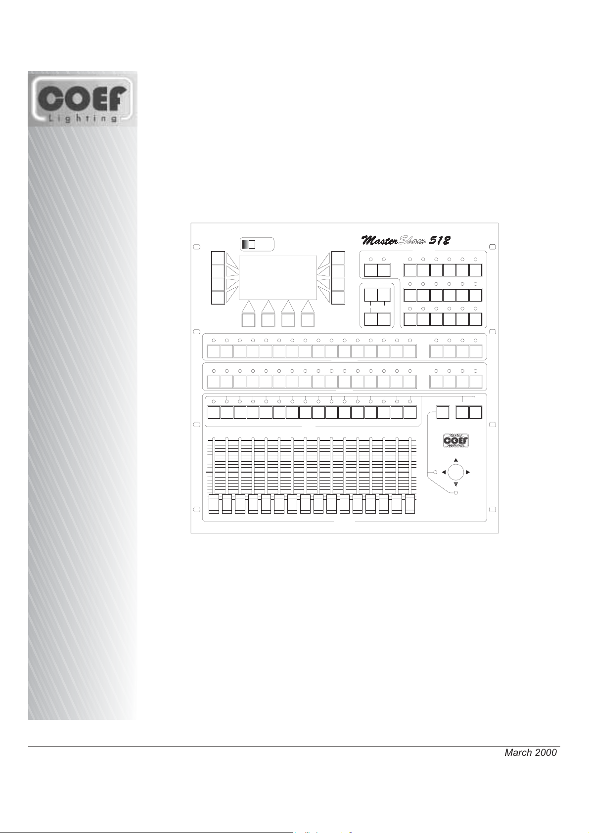
Programmable Console
August 2005
POWER
GROUP
BLACKOUT
SEQUENCER
PAUSE
TIMES
STAND
DOWN UP
CROSS
13
11
12
10
9
8
7
6
4
2
1
17
18
33
34
50
49
1
2
17
18
33
34
49
50
5
3
19
35
51
3
19
35
51
22
20
21
38
36
37
54
52
53
4
5
6
20
21
22
36
37
38
52
53
54
25
24
23
41
40
39
57
56
55
7
8
9
23
24
25
39
40
41
55
56
57
26
42
58
PROJECTORS
10
26
42
58
28
29
27
44
45
43
61
59
60
11
12
13
29
27
28
45
43
44
61
59
60
PROGRAMS
3-21
2-20
1-19
9-27
8-26
7-25
15-33
14-32
13-31
16
15
14
31
30
47
46
63
62
14
15
30
31
46
47
62
63
32
48
64
16
32
48
64
1/16 17/32 33/48 49/64
1/16 17/32 33/48 49/64
4-22
10-28
16-34
5-23
11-29
17-35
6-24
12-30
18-36
LIBRARY
51234 106 7 8 9 11 12 13 14 15 16
TAB
255
SELECT DOWN UP
FINE ADJUSTMENT
255
17/X
0
CHANNELS
0
16151413121110987654321
18/Y
• OPERATING INSTRUCTIONS
MASTERSHOW 512
Printed in March 2000
Page 2
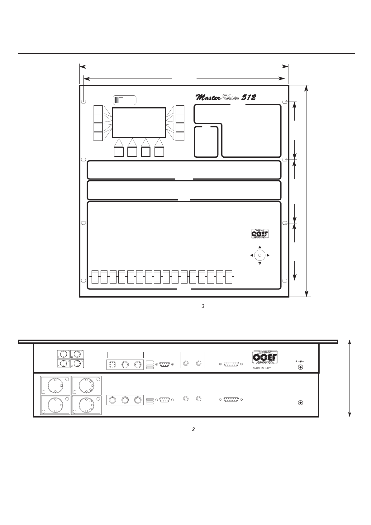
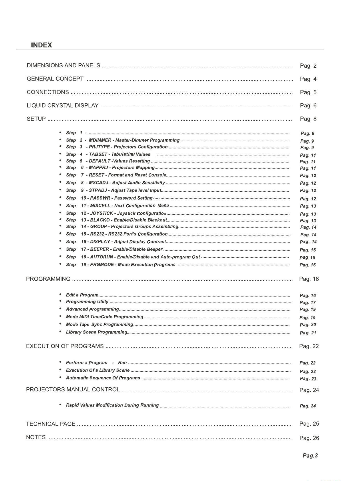
DIMENSIONS and PANELS
2
3
483.00
465.00
POWER
DISPLAY SECTION
TIMES
TIMES
SECTION
PROJECTORS SECTION
PROJECTORS
LIBRARY SECTION
LIBRARY
CHANNELS SECTION
PROGRAMS
PROGRAMS SECTION
133.50
146.00
488.15
133.50
PIN 1=GND
PIN 2=SIGNAL -
PIN3=SIGNAL+
DMX OUT2
DMX OUT4
DMX OUT1
DMX OUT3
MIDI
OUTIN THRU
MIC RS 232
CHANNELS
Figure 3
AUDIO IN
Figure 2
16151413121110987654321
CHSSI POWER SUPPLY
COEFHIGH SPEED SERIAL INTERFACE
LR
PonteBuggianese (Pistoia)
MADE IN ITALY
+
25 VDC 20%0.5A
-
max 130 mm.
Pag.2
Page 3
Page 4
L
C
Page 5
CONNECTIONS
CHSSI POWER SUPPLY
COEFHIGHSPEED SERIALINTERFACE
DMX
OUT
PonteBuggianese (Pistoia)
MADE IN ITALY
From
DC Adapter
PIN1=GND
PIN2=SIGNAL -
PIN3=SIGNAL +
POWER
IN
Figure 4
DMXOUT1
DMXOUT2
DMXOUT3
DMXOUT4
25VDC 20% 0.5A
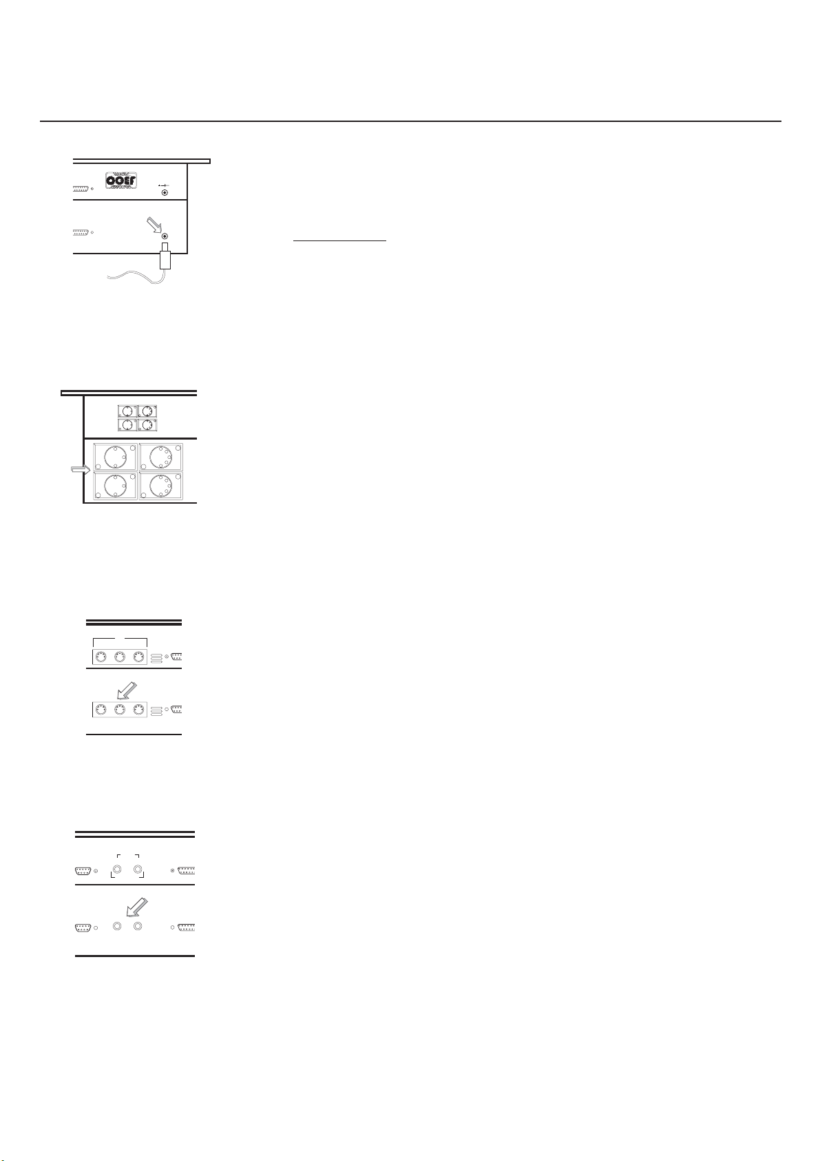
Take out the provided DC adapter and plug it into the relevant socket in the
MASTERSHOW 512 back panel (see Fig. 4).
ATTENTION!!
The voltage furnished by the above mentioned DC adapter
must be 25 Volts DC and 0.5A.
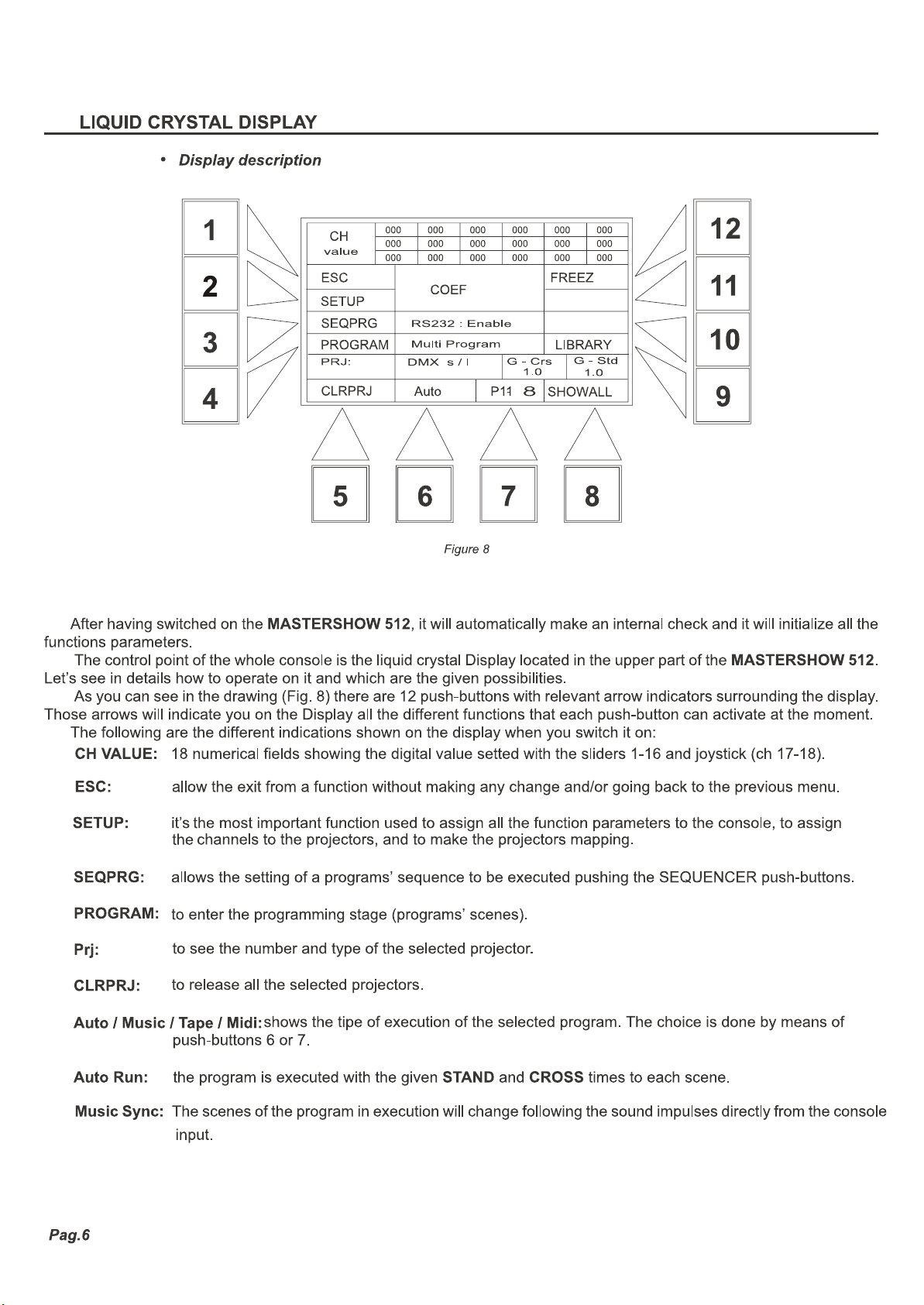
Connects the units to be checked to the outlets indicated in Fig. 5. Pay atten-
tion that the cables and the connectors don’t present short-circuits that could damage the DMX outputs of the MASTERSHOW 512.
RS 232
Figure 5
MIDI
OUTIN THRU
Figure 6
SYNC
OUT
IN
L
AUDIO IN
MIC RS 232
MIDI in
out
R
Audio &
Sync in/out
CHSSI
COEFHIGH SPEEDSERIAL INTERFACE
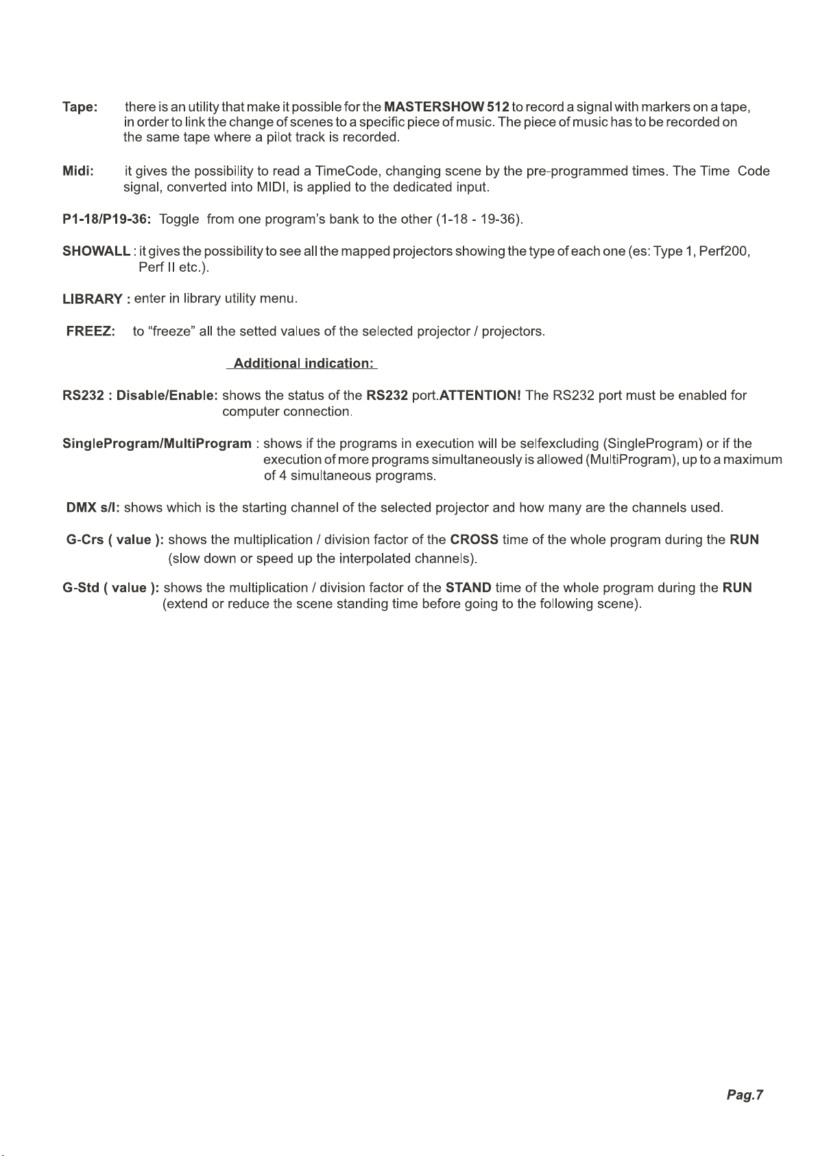
Connect the cables from and for MIDI units to the prearranged socket in the
back panel of the MASTERSHOW 512, taking care of input and output indications
clearly serigraphated on the same panel.
Audio & sync in/out can be used to connect the external musical sources. Toget
the audio signals or to get the signals recorded on an audio track. The audio track
will allow a program execution synchornized with a certain piece of music.
Figure 7
Pag.5
Page 6
Page 7
Page 8
SETUP
•
Step 1
ESC
MDIMMER
PRJTYPE
MAPPRJ
SetupMenu
MasterShow
512
Verx.xx
PGRMODE
MISCELL
GROUP
SEQUENCER
B
TIMES
STAND
DOWN UP
CROSS
F G
BLACKOUT
PROGRAMS
1-19
PAUSE
C
7-25
ED
13-31
2-20
8-26
14-32
3-21
9-27
15-33
4-22
10-28
16-34
5-23
11-29
17-35
A
6-24
A
12-30
A
18-36
RESET MSCAD JSTPAD JPASSWR
Figure 9
Figure 10
This is an extremely important stage, in order to obtain a correct functioning of the controlled projectors and in order to ope-
rate in the most safe and quick way.
Pushing the n.2 (SETUP) push-button the display will show a new menu (Fig. 9). Let’s see the new menu in details.
ATTENTION!
The first time that you enter the SETUP after having switched the console on, you will be required to insert a
Password composed of 6 figures, that have to be inserted by means of PROGRAMS push-buttons. The default Password, is
the following: 1- 2- 3- 4- 5- 6.
There is the possibility to set a personal PASSWORD, that can be inserted in the SETUP stage (see STEP 10).
ESC: go back to the previous Menu.
MDIMMER: go to the Master Dimmer Setup function
PRJTYPE: 16 types of projectors for a maximum of 18 channels each, to be configurated by the user, and the COEF
projectors.
MAP PRJ: to assign a certain type of projector to any of the 64 controllable projectors.
RESET: console formatting and reset of all the parameters. ATTENTION!
All data will be cancelled, including the
personal PASSWORD.
MSCADJ: to adjust both the microphonic and the on line input sensitivity, to be connected to the AUDIO IN inputs
of the console.
STPADJ: to adjust the input level and the gain of the Tape Sync.
PASSWR: to set the personal password.
MISCELL: one other Setup utility menu (Display, Beeper, RS232, etc).
PRGMODE: to set the way of execution of the programs (SingleMode / MultiMode).
Pag.8
Page 9

Step 2 - MDIMMER - Master-Dimmer Programming
•
MasterDimmerSetup
255
ESC Ch-MS512:Off
SlgOff.:0
Figure 11
0
87654321
Figure 12
After pressing the push-button 2 (Fig.8 pag. 6) the display will show as in Fig 11.The basic idea of the Master-Dimmer is to
have a slider exclusively dedicated to: instant opening/closing of the shutters; light adjustment of all projectors simultaneously;
and any other kind of control that should be possible by means of only one slider at any time, regardless of the present function
of the MASTERSHOW 512.
It’s possible to assign this function to one of the 16 sliders
by means of slider 1 (Fig.12) marking the number on the display
in Ch-MS512: Off means that you will not have the Master-Dimmer control.
The mark “Slg Off” will allow you, by means of slider 2, to set the minimum level reachable by the Master-Dimmer control
slider. For example:
Set the Ch-MS512 to value 16 using the slider 1 (Fig. 12); so you have enabled the slider 16 to the Master-Dimmer function.
Now slide up the slider 2 untill you read the value 100 next to Slg Off. If all your projectors would be enabled to the MasterDimmer function ( see step 3) on the channel corresponding to the shutter, you will be able to control in unison all the projectors shutters by means of slider 16, without going below the value of 100 DMX, setted as described before.
Press ESC to return to the previous menu storing the operation.
•
Step 3 - PRJTYPE - Projectors Configuration
Projector:TYPE01Ch:1
ESC
Ch-MS512:Off
Ch-Type.:Dir
NEXT
PREVIUS
Dimmer..:Dis
Shutter.:Dis
VShutOff.:0
TABSET DEFAULT
Figure 13
CHUP
CHDW
255
0
87654321
Figure 14
Pag.9
Page 10

Page 11

V
R
M
Page 12

S
L
I
Password
S
Page 13

C
C
M
Page 14

G
A
P
C
C
Page 15

B
O
E
P
Page 16

P
Page 17

Page 18

Page 19

P
P
Page 20

P
Page 21

S
P
Page 22

P
O
S
Page 23

S
P
O
Page 24

PROJECTORS MANUAL CONTROL
000 000 000 000 000 000
CH
000 000 000 000 000 000
value
51234 106 7 8 9 111213141516
TAB
255
0
16151413121110987654321
CHANNELS
255
0
SELECT DOWN UP
HI
FINE ADJUSTMENT
17/X
18/Y
L
Figure 62
It can also be done while one or more programs are in execution. The selected projector will be in manual control and, if the
choosen projector was part of the running program, it will be temporarily isolated from the program itself and you will have it in
manual control.
If you press the projector push-button again, the projector will return to operate within the program. On the contrary if you
wish that the projector or the projectors will remain in manual control without them going back to operate within the programs,
you have to push P12 (FREEZ), freezing in this way their positions till you will select them again pressing their relevant pushbuttons. The led on the “frozen” projectors will flash in a different way.
000 000 000 000 000 000
ESC
UTILITY SCENE..:1
CH-KEY
RUN
PRJ :
CLRPR JINSERT
S-Crs S-Std
2.0 .1
PROGRAM:1
AutoRUN
DMX s / l
DELETE SC-KEY
G-Crs
Figure 61
000 000 000 000 000 000
CH
000 000 000 000 000 000
value
000 000 000 000 000 000
ESC
ChannelChangeActive!
CH-CNGAutoRUN
PRJ :
UNSALL Resume
S-Std
S-Crs
1.0
DMX s / l
1.0
G-Crs
SCENE:1
PROGRAM: 1
Channel SELALL
Figure 60
1.0
1.0
SCUP
SCDWN
G-Std
FREEZ
SC UP
SCDW
N
REPEAT
G-Std
1.0
1.0
The FINE ADJUSTMENT push-buttons in the CHANNELS section (part. H-I-L Fig.62) are dedicated to fine adjustment
of the channels selected by means of sliders, joystick, channels push-buttons, or with the SELECT push-button (part. H Fig.
62) that gives a selection for channels 17 or 18 of the Joystick.
•
Rapid values modification during running
The mark CH-CNG (Channel Change) is another utility, setted by P4 (see Fig60-61): it allows to change, in a total and ra-
pid way, the value of a channel on the projectors you’re selecting and that are included in the program in execution.
You have the possibility to:
selectthemallbyP8(SELALL)
de-select them by P5 (UNSALL)
go them back to the program control by P6-P7 (Channel Resume).
Pag.24
Page 25

Page 26

®
Realization:
PC CAD & VIDEO
 Loading...