

Page 1

Horizon
®
USER’S MANUAL
®
Page 2

®
®
Horizon
Multi-media
Dry Imager
Starter Manual
Codonics® Catalog Number H-START-EN
Nov 21, 2005
Version 1 . 8.3
Codonics, Inc.
17991 Englewood Drive
Middleburg Heights, OH 44130 USA
440-243-1198 Phone
440-243-1334 Fax
Email info@codonics.com
www.codonics.com
Page 3

Copyright © 2005 by Codonics, Inc. All rights reserved, worldwide. Printed in the
U.S.A. Part Number 905-042-001.
No par t of thi s documen t may b e copied o r re produ ced in any form by any mean s
without prior written consent of Codonics, Inc., 17991 Englewood Dr.,
Middleburg Heights, Ohio 44130 U.S.A.
Although every effort has been made to ensure the accuracy of this document,
Codonics, Inc. assumes no responsibility for any errors that may appear.
Codonics, Inc. makes no commitment to update nor to keep current the
information contained in this document.
The Horizon imager is protected by the following patent number: US Patent No.
6,249,299 System for Printhead Pixel Heat Compensation. All other patents are
pending.
Horizon, DirectVista, ChromaVista, the Codonics logo, and “We bring the future into focus”
are registered trademarks, and Codonics, Variable Multiformatting, VMF, Fixed
Multiformatting, FMF, Medical Color Matching, MCM, SlideMaker, and Bracketing are
trademarks of Codonics, Inc.
Windows and Windows NT are registered trademarks of Microsoft Corporation.
PostScript is a registered trademark of Adobe Systems Incorporated.
Apple and Macintosh are trademarks of Apple Computer, Inc., registered in the U.S. and
other countries.
UNIX is a registered trademark of The Open Group.
Linux is a registered trademark of Linus Torvalds.
Zip is a registered trademark of Iomega Corporation.
StuffIt is a trademark of Aladdin Systems, Inc.
PKZIP is a registered trademark of PKWARE, Inc.
Intel is a registered trademark of Intel Corporation or its subsidiaries in the United States
and other countries.
All other registered and unregistered trademarks are the property of their respective
owners.
European Authorized Representative:
CEpartner4U
Esdoornlaan 13,
3951DB Maarn
The Netherlands
Tel.: +31 (0)6.516.536.26
Page 4

Contents
Preface
Manual Conventions .................................................................................... -vii
Bulleted Lists......................................................................................... -vii
Numbered Steps ................................................................................... -vii
Control Panel Navigation ..................................................................... -viii
Control Panel Keys .............................................................................. -viii
Control Panel Menu Options................................................................ -viii
Notes.................................................................................................... -viii
Cautions and Warnings........................................................................ -viii
Purpose and Scope ...................................................................................... -ix
Product Information ...................................................................................... -x
Disposal Requirements ................................................................................ -xi
Warnings and Limitations of Use................................................................. -xii
Location of Safety and Compliance Labels........................................... -xii
Voltage Warning................................................................................... -xiii
Laser Warning...................................................................................... -xiv
Temperature Warning ........................................................................... -xv
Compliance ........................................................................................... -xv
Serial Number, Configuration, Date Code, and Modification Codes.... -xvi
ESD Caution ....................................................................................... -xvii
Potential for Radio Frequency Interference on Imager Operation ...... -xvii
Potential for Radio and Television Interference ................................. -xviii
Safety Precautions ............................................................................... -xix
Location Precautions............................................................................ -xxi
Cleaning Precautions .......................................................................... -xxii
Media .................................................................................................. -xxii
File Transfer via FTP and LPR........................................................... -xxiv
Color Management............................................................................. -xxiv
Contents
Horizon Starter Manual iii
Page 5

Image Scaling .................................................................................... -xxiv
Hardware Variations............................................................................ -xxv
Indications for Use ..................................................................................... -xxv
Chapter 1: Setting Up the Imager
Preparing for Installation............................................................................. 1-1
Installing the Imager ................................................................................... 1-2
Connecting the Ethernet Cable .................................................................. 1-6
Powering On the Imager—First Time......................................................... 1-8
Cleaning the Platen Roller ................................................................... 1-9
Network Settings—Simple Network.......................................................... 1-10
Specifying the Imager’s IP Address ................................................... 1-11
Determining an IP Address.......................................................... 1-11
Specifying the Imager’s IP Address at the Control Panel ............ 1-12
Specifying IP Addresses for Other Devices on the Network .............. 1-14
Loading Media .......................................................................................... 1-15
Preparing the Imager for Shipment .......................................................... 1-15
iv Contents
Chapter 2: Basic Imager Operations
Horizon Imager Components...................................................................... 2-1
Powering the Imager On and Off................................................................ 2-3
Powering On the Imager ...................................................................... 2-3
Observing the Imager’s Operating Status in the Status Screen........... 2-4
Common Cassette Status Messages ............................................ 2-5
Color Ribbon Status....................................................................... 2-6
Powering Off the Imager ...................................................................... 2-7
Understanding the Control Panel ............................................................... 2-8
Control Panel Indicators....................................................................... 2-9
Alert and Fault Messages and the Fault Tone ................................... 2-10
Control Panel Display......................................................................... 2-10
Main Menu ................................................................................... 2-10
Page 6

Chapter 3: Media Handling and Storage
Overview..................................................................................................... 3-1
Supply Slots and Cassettes ................................................................. 3-1
Viewing the Status of a Supply Slot............................................... 3-3
Inserting or Changing Cassettes ................................................................ 3-4
Handling and Storing Media ....................................................................... 3-6
Break-Off Leaders (ChromaVista Only) ............................................... 3-6
Changing the Ribbon (ChromaVista).......................................................... 3-7
Ordering Media ......................................................................................... 3-10
Chapter 4: Printing from DICOM Applications
Introduction to DICOM ................................................................................ 4-1
DICOM Conformance Statement ......................................................... 4-2
Configuring the DICOM Application............................................................ 4-2
Sending a DICOM Print Job ....................................................................... 4-3
Specifying the Media Type and Size.................................................... 4-3
Using Job Settings Files with DICOM......................................................... 4-3
Categories of Job Settings................................................................... 4-4
Specifying a Job Settings File from a DICOM User Application........... 4-4
Hierarchy of Settings Used by the Horizon Imager .............................. 4-5
Contents
Chapter 5: Printing from Windows via PostScript
Introduction to PostScript ........................................................................... 5-2
Printing from Windows Applications ........................................................... 5-2
Notes About Changing PostScript Parameters.............................. 5-2
Changing Horizon PostScript Parameters—Windows 2000
and XP........................................................................................ 5-3
Chapter 6: Default Print Job Settings
Changing the Default Settings.................................................................... 6-2
Changing the Default Media Type and Size......................................... 6-2
Changing the Default User Settings..................................................... 6-3
Horizon Starter Manual v
Page 7

Chapter 7: Preventive Maintenance
Recommended Maintenance Schedule...................................................... 7-1
Horizon Cleaning Kits........................................................................... 7-2
Cleaning the Thermal Print Head and Platen Roller................................... 7-3
Cleaning the Pick Tires............................................................................... 7-7
Chapter 8: Film Calibration
Chapter 9: Troubleshooting
Sources of Status Information .................................................................... 9-1
Control Panel ....................................................................................... 9-1
Error Log .............................................................................................. 9-1
Online Help for Displayed Messages................................................... 9-1
Troubleshooting Tables .............................................................................. 9-2
Status Message Tables .............................................................................. 9-8
Common Cassette Status Messages................................................... 9-8
Color Ribbon Status ............................................................................. 9-9
Clearing a Sheet Jam ................................................................................. 9-9
Clearing a Jam from a Cassette......................................................... 9-12
Clearing a Jam from the Printing Area............................................... 9-14
Reinstalling Media Guides ................................................................. 9-17
Purging Print Jobs .................................................................................... 9-19
Contacting Technical Support .................................................................. 9-20
vi Contents
Appendix A: Specifications
Appendix B: System Job Settings Files
Index
Page 8

Preface
Manual Conventions
8
To access the
Main Menu
and scroll
through menu
options
Bulleted Lists
Bullets are used to display a list of nonprocedural items. For
example:
The control panel contains:
• A display panel
•Keys
•Indicators
Numbered Steps
The
8
in a procedure are numbered. For example:
1. Press the key.
The Main Menu displays on the control panel. The selector
arrow (X) automatically points to the first menu option.
2. To scroll through the menu options, press the and keys.
The selector arrow (
The bottom portion of the control panel display shows a
message associated with the currently selected menu option.
icon indicates the beginning of a procedure. The steps
MENU
S
X
) moves up and down through the list.
T
Preface
Horizon Starter Manual vii
Page 9

Control Panel Navigation
Menu paths
are used in some procedures instead of documenting
every step needed to navigate to a specific menu option. For
example:
From the Main Menu, select the following options:
Default Media
Grayscale
DV Film Blue
Control Panel Keys
Control panel keys are shown in small black ovals to resemble the
actual keys, for example, “Press the key.”
ENTER
Control Panel Menu Options
Control panel menu options are shown in bold type, for example,
“Select the
Gamma
menu option.”
Notes
Notes contain additional information related to a topic or
procedure. For example:
3
viii Preface
NOTE:
If your network is managed by a network administrator or an information technology
(IT) department, it would be considered a complex network. You should have the
responsible person perform any network-related administrative tasks.
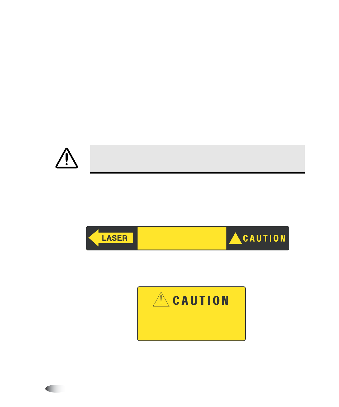
Cautions and Warnings
Cautions alert you to actions or situations that could cause harm to
equipment or data. For example:
CAUTION
made by other users. Use caution when changing default settings.
Any changes you make to the imager default settings will also affect prints
Page 10
Warnings alert you to actions or situations that could result in
personal injury. For example:
WARNING With the imager cover open, touch only those internal components
that are colored green (except for the pick tires).
Purpose and Scope
3
Refer to this Starter Manual for procedures on how to perform the
most common imager operations, including:
•
Setting up the imager
•
Loading media
•
Sending print jobs from DICOM Print Service Class-compliant
applications running on imaging devices or image viewing
workstation
•
Changing the imager’s default image and sheet settings
•
Adjusting the appearance of printed images for user preference
•
Performing preventive maintenance
•
Performing film calibration
•
Troubleshooting common problems
NOTE:
This manual is current to the Horizon Imager v1.8.3 software. Some features and
functions described here may not apply to older versions of the software.
Preface
Horizon Starter Manual ix
Page 11

This Starter Manual is intended to be as simple and straightforward
as possible for the everyday user. If you need more detailed or more
technical information on a feature or topic, or wish to perform more
advanced operations, refer to the
Manual
User’s Manual
(Catalog no. HORIZON-MNLT) and the
(Catalog no. HORIZON-MNLU). The Technical
Manual serves as a companion document to this manual.
Product Information
For technical assistance with Codonics products, call the Codonics
“On Call” Technical Support System at one of the following
numbers:
Phone: +1.440.243.1198
Toll Free: 800-444-1198 (USA Only)
The “On Call” Technical Support System provides for around-theclock availability of qualified technical support personnel.
Horizon Imager Technical
Horizon Imager
You can also e-mail Technical Support at
xPreface
support@codonics.com
.
Page 12
Disposal Requirements
Disposal of this product shall be in accordance with all applicable
laws and regulations in effect at the locality at the time of disposal.
European Disposal Requirements
Codonics imagers and electronic accessory devices are not to be
discarded or recycled; rather they are to be returned to the
manufacturer. Contact Codonics directly or by the link provided for
the latest information concerning:
•
Identification of the country specific
Importer/Distributor/Producer
•
Product return and treatment of our electronic products
Manufacturer: Codonics Incorporated
17991 Englewood Drive
Middleburg Heights, OH 44130 USA
Phone: +1.440.243.1198
Fax: +1.440.243.1334
Email: WEEE@codonics.com
www.codonics.com
Preface
Codonics imagers and electronic accessory devices bearing this
symbol are subject to European Directive on Waste Electrical and
Electronic Equipment (WEEE) 2002/96/EC, amended by Directive
2003/108/EC. The EN 50419 symbol indicates separate collection
and return required.
Horizon Starter Manual xi
Page 13
Warnings and Limitations of Use
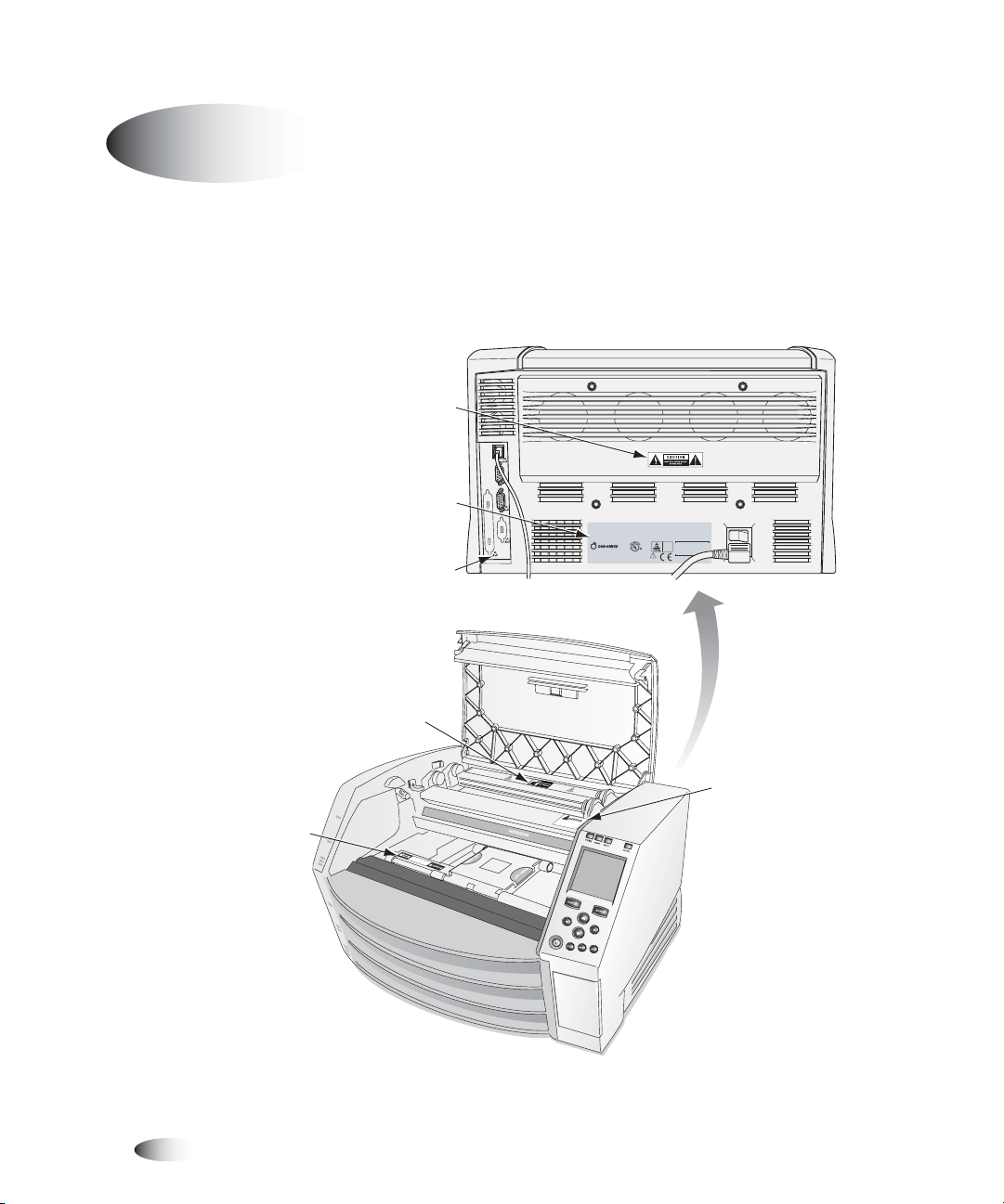
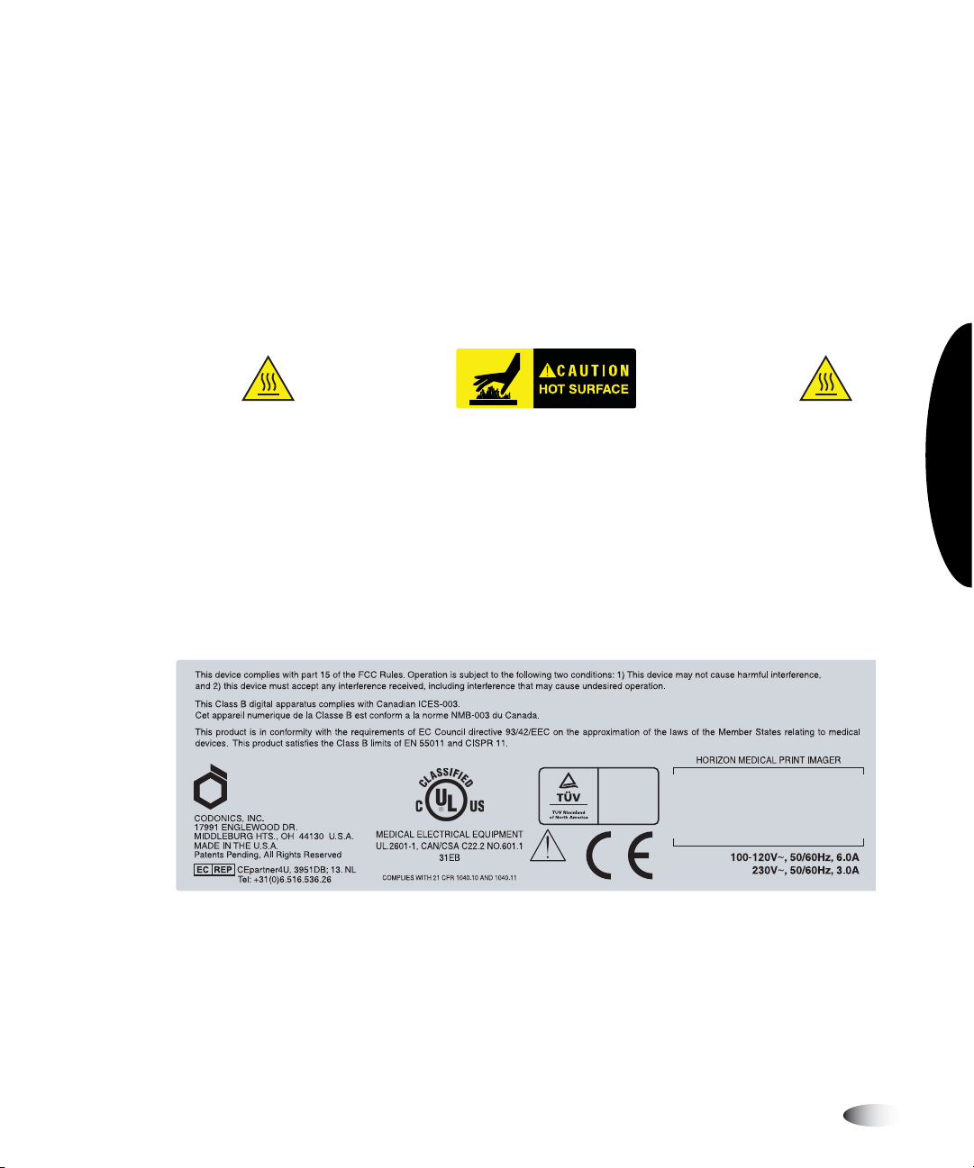
Location of Safety and Compliance Labels
The following figure shows the locations of the imager’s safety and
compliance labels.
Shock warning label
K
R
O
W
T
E
N
E
L
O
S
N
CO
S
P
Compliance label
ESD label
U
This equipment has been type tested and found to comply with the requirements in part 15 of FCC rules and Canadian Department of communications for a Class B
computing device. See instruction manual. Operation in a residential area may cause unacceptable interference to radio and TV reception requiring the operator to
take whatever steps are necessary to correct the interference.
Le pr sent appareil num rique n' met pas de bruits radio lectriques d passant les limites applicables aux appareils num r iques de la Classe B prescrites dans le
R glement sur le brouillage radio lectrique dict par le minist re des Comm unications du Canada.
This product is in conformity with the requirements of EC Council directive 93/42/EEC on the approximation of the laws of the Member States relating to medical
devices. This product satisfies the Class B limits of EN 55011 and CISPR 11.
CODONICS, INC.
17991 ENGLEWOOD DR.
MEDICAL ELECTRICAL EQUIPMENT
MIDDLEBURG HTS., OH 44130 U.S.A.
UL.2601-1, CAN/CSA C22.2 NO.601.1
MADE IN THE U.S.A.
Patents Pending, All Rights Reserved
AR: CEpartner4U, 2635 HL 33.NL
Tel: +31(0)6-516.536.26
31EB
COMPLIES WITH 21 CFR 1040.10 AND 1040.11
HORIZON MEDICAL PRINT IMAGER
EN 60601-1
100-120V, 50-60Hz, 6.0A
V, 50-60Hz, 3.0A
230
Laser warning
xii Preface
Hot surface warning label
label 1
Laser warning
C
L
A
S
S
2
L
A
O
SE
PE
R
N
R
A
AD
N
D
I
A
I
N
T
I
T
O
E
N
R
DO
W
L
O
H
N
CK
E
O
N
T
S
ST
D
E
AR
F
E
E
A
I
T
N
E
T
D
O
B
EAM
L
A
A
V
S
O
E
I
R
D
R
E
A
X
F
D
R
P
O
O
I
A
S
M
T
U
I
T
O
R
H
N
E
I
S
I
S
A
E
P
M
E
I
R
T
T
T
U
E
R
D
E
!
label 2
Page 14
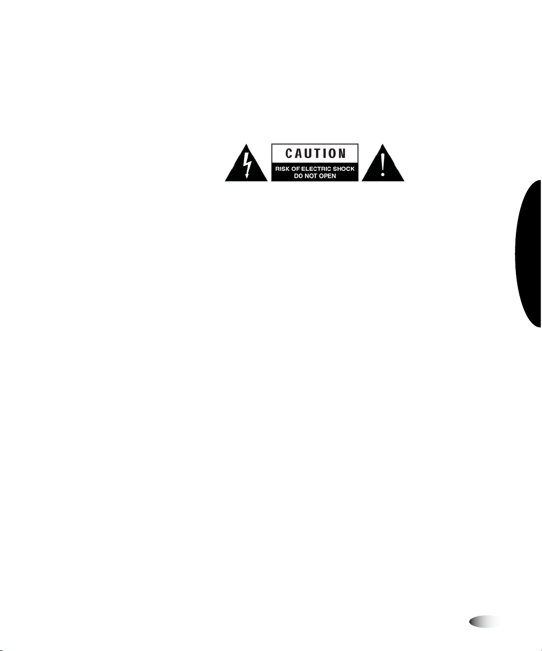
Voltage Warning
The lightning flash with arrowhead symbol, within an equilateral
triangle, is intended to alert the user to the presence of uninsulated
“dangerous voltage” within the product’s enclosure that may be of
sufficient magnitude to constitute a risk of electric shock.
The exclamation point within an equilateral triangle is intended to
alert the user to the presence of important operating and
maintenance (servicing) instructions in the literature accompanying
this imager.
NO USER-SERVICEABLE PARTS INSIDE. REFER SERVICING TO
QUALIFIED SERVICE PERSONNEL. REMOVAL OF LABELS,
COVERS, OR ENCASEMENT FASTENERS VOIDS THE WARRANTY.
THIS APPARATUS MUST BE ELECTRICALLY GROUNDED.
TO PREVENT FIRE OR SHOCK HAZARD, DO NOT EXPOSE THIS
IMAGER TO RAIN OR MOISTURE.
Preface
EQUIPMENT IS NOT TO BE USED AS A COMPONENT OF A LIFE
SUPPORT SYSTEM. Life support devices or systems are devices or
systems that support or sustain life, and whose failure to perform
can be reasonably expected to result in a significant injury or death
to a person. A critical component is any component of a life support
device or system whose failure to perform can be reasonably
expected to cause the failure of the life support device or system,
or to affect its safety or effectiveness.
Horizon Starter Manual xiii
Page 15
Laser Warning
The Horizon imager uses a laser to read barcode information on the
media cassettes. The laser module is a 670-nm, 1.26-mW device. As
such, it has been found to comply with the 21 CFR 1040.10 and
1040.11 and IEC 60825 laser standards as a low power Class 1
device.
For safety reasons, the laser is turned on only for a short time when
a cassette is inserted. Still, one should use caution and never stare
at the laser beam, should avoid exposure to the laser, and should
never override any of the interlocks and safety mechanisms. These
measures are taken for your protection.
WARNING Use of controls or adjustments to the performance of procedures
other than those specified in this manual may result in hazardous radiation
exposure.
The laser apertures are marked with a single label, shown below.
There are three apertures that correspond to the three cassette
locations, one for each, on the same side of the Horizon imager as
this label.
xiv Preface
AVOID EXPOSURE
LASER RADIATION IS EMITTED
FROM THIS APERTURE
!
Safety interlocks are marked by the following label. They are
located on the same side of the Horizon imager as this label.
CLASS 2 LASER RADIATION WHEN
OPEN AND INTERLOCKS DEFEATED
DO NOT STARE INTO BEAM
The locations of the two laser labels are shown in the figure on
page xii.
Page 16
Temperature Warning
Because the Horizon imager is a thermal print device, the surface
of the thermal print head heat sink gets hot. Avoid directly touching
any components not colored green when accessing the interior of
the imager if the imager has been printing. (During some
preventative maintenance tasks, you will be touching internal
components with cleaning pads or swabs.)
The temperature warning label is shown below.
Compliance
Codonics is in compliance with various regulations, of which details
are listed in Appendix A.
The Compliance label, which is affixed at the back of the imager, is
shown below.
Preface
CODONICS
EN 60601-1
Horizon Starter Manual xv
Page 17
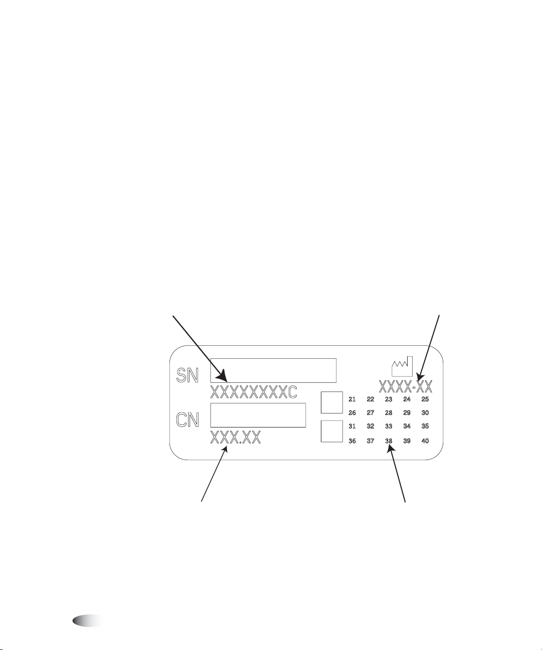
Serial Number, Configuration, Date Code,
and Modification Codes
The Serial number label is placed onto the Compliance label. It
includes the following information:
•
The serial number (SN), which uniquely identifies the unit.
•
The configuration number (CNFG), which details the build
configuration.
•
The modifications codes, which are to the right of the CNFG
number and are a series of 20 numbers. When any of these
numbers are blocked out, that identifies a modification that was
made to the unit.
•
The date code in YYYY-MM format below the factory date code
symbol.
Serial number Date code
xvi Preface
Configuration number Modification codes
Page 18
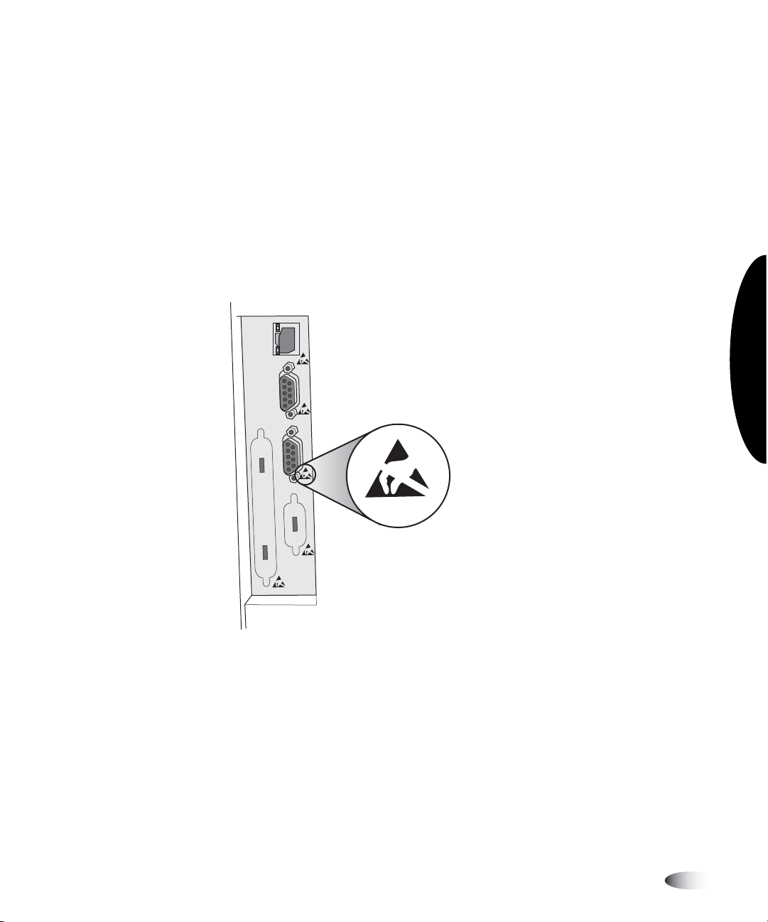
ESD Caution
Connections to other pieces of equipment are made at the rear of
the Horizon imager. These connectors are marked with a
precautionary ESD warning symbol, as shown below. Do not touch
any of the pins of these connectors. When making connections to
the imager, it is best done while the imager is plugged in but not
powered on. ESD may cause erratic behavior of the imager when
powered on. Should this occur, power to the imager may have to be
cycled. It is recommended that all staff involved in making
connections to the imager be aware of these ESD precautions.
NETWORK
CONSOLE
UPS
Potential for Radio Frequency Interference
on Imager Operation
Both portable and mobile RF communications equipment can affect
medical electrical equipment, including the Horizon imager. Keep
such RF communications equipment out of the immediate area.
Preface
Horizon Starter Manual xvii
Page 19

Potential for Radio and Television
Interference
The Horizon imager generates and uses radio frequency energy,
and if not installed and used properly, that is, in strict accordance
with the manufacturer’s instructions, may cause interference to
radio and television reception. It has been type tested and found to
comply with Class B emission limits for a computing device in
accordance with the specifications in Subpart J of Part 15 of FCC
Rules, which are designed to provide reasonable protection against
such interference when operating in a commercial environment.
Operation of the equipment in a residential area is likely to cause
interference, in which case the user, at his own expense, will be
required to take whatever measures may be appropriate to correct
the interference. If your imager does cause interference to radio or
television reception, you are encouraged to try to correct the
interference by one or more of the following measures:
•
Reorient the receiving antenna
•
Relocate the imager with respect to the receiver
xviii Preface
If necessary, you should consult Codonics technical support or an
experienced radio/television technician for additional suggestions.
You may find the following booklet prepared by the Federal
Communications Commission helpful:
Radio-TV Interference Problems
. This booklet is available from the
How to Identify and Resolve
U.S. Government Printing Office, Washington, D.C. 20402, Stock
No. 004-000-00345-4.
Le présent appareil numérique n’émet pas de bruits radioélectriques dépassant les limites applicables aux appareils
numériques de la Classe B prescrites dans le Réglement sur le
brouillage radioélectrique édicté par le ministére des
Communications du Canada.
Page 20

This product is in conformity with the protection requirements of
EC Council directive 89/336/EEC on the approximation of the laws
of the Member States relating to electromagnetic compatibility. This
product satisfies the Class B limits of EN 55011. A declaration of
conformity with the requirements of the Directive has been signed
by the Director of Quality Assurance and Regulatory Affairs.
Safety Precautions
•
Never connect this imager to any outlet or power supply that has
a voltage or frequency different than that specified on the rear of
the imager.
•
When servicing the imager, always power it off using the
(power) key at the control panel, then turn the rocker switch
in the back to the 0 (off) position, then unplug the imager.
•
Damage to the power cord may cause fire or shock hazard. When
unplugging the power cord, hold it by the plug only and remove
the plug carefully.
•
If the power cord needs to be replaced, replace it only with
another Codonics power cord manufactured specifically for your
imager’s power configuration.
•
If the imager is smoking or making unusual sounds, power off
and unplug the imager immediately.
•
Do not insert foreign objects of any kind into the imager; doing
so can constitute a safety hazard and cause extensive damage.
Preface
Horizon Starter Manual xix
Page 21
•
Do not place any liquid containers on the imager. If, for some
reason, liquid seeps into the imager, power off the imager and
unplug the power cord from the source outlet. If used without
corrective measures, the imager may be damaged.
•
Do not use the imager near flammable gases.
•
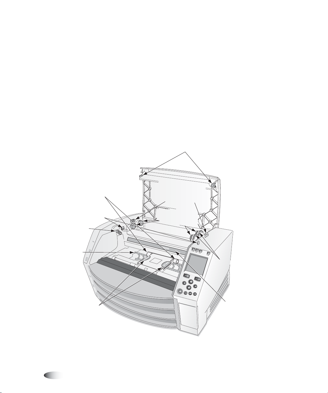
With the imager top cover open or the receive trays removed,
touch only those internal components that are colored green
(except for the pick tires). Remove rings, ties, jewelry, and other
items, and tie back hair, so that they do not fall into or get caught
in the imager.
Top cover releases
(DO NOT TOUCH except with
Pick Tires
Platen Roller Cleaning Wipe)
Upper fender releases
(down position)
Top cover
master release
Media
guides
Picker
(lift here)
Internal Components That Are Colored Green (called out in the
illustration) Are Safe to Touch (except for the pick tires)
Upper fender
releases
(up position)
Spring-loaded
spindles
Spool wheels
Diverter
xx Preface
Page 22

Location Precautions
•
The imager’s operating ambient temperature range is 15–30ºC
(59–86ºF), with a relative humidity of 10%–80%, non-condensing.
•
If the imager is moved quickly from an extremely cold place to a
warmer one, condensation is likely to form. Do not use the
imager if condensation has formed. Wait until the condensation
has evaporated. You can speed up the evaporation time by
moving the imager to a dryer location.
•
Ventilation slots and holes are provided on the sides and rear of
the imager. Place the imager on a hard level surface and locate it
at least 10 cm (4 in.) from walls to ensure proper ventilation.
CAUTION
•
Do not place imager in a high humidity or high dust area.
Airborne dirt particles can cause image quality problems. Avoid
placing the imager in areas where ventilation ducts, open doors,
or frequent passers-by might expose the imager and media to
high levels of debris.
Adequate ventilation is required for proper operation of the imager.
Preface
•
Do not locate the imager in hot-springs areas where hydrogen
sulfide and acidic ions are likely to be generated.
•
Do not locate the imager where there are oily fumes and vapors.
•
Do not locate the imager in direct sunlight.
•
Do not locate imager near sources of high RF energy.
•
Do not locate the imager where it might be subject to jarring or
vibrations, such as a table or desk in a high-traffic area. Jarring
and vibrations can affect the print quality of images.
Horizon Starter Manual xxi
Page 23

Cleaning Precautions
•
Many plastic components are used in the imager’s construction.
Coat flecking and deformation is likely to occur if the imager is
wiped with chemical dusters, benzene, thinners, insecticides, or
other solvents. Rubber and PVC materials left in contact with the
imager for extended times will cause damage. Never use
petroleum-based solutions or abrasive cleaners.
•
To clean the imager cover, first power off the imager using the
(power) key at the control panel, then turn the rocker switch
in the back to the 0 (off) position, then unplug the imager. Clean
the cover with a soft cloth slightly moistened with a mild soap
and water solution. Allow the cover to completely dry before
operating the imager again.
Media
•
For
ChromaVista® color prints, the consumed ribbon contains
facsimiles of any patient images printed to
sheets. Therefore, you must properly dispose of or destroy
consumed ribbon to ensure the confidentiality of patient images.
ChromaVista
color
xxii Preface
•
The optical density of reflective and transmissive prints have a
nominal range of: Dmin = 0.10 OD (reflective), 0.11 OD
(transmissive) to Dmax = 2.10 OD (reflective), 3.1 OD
(transmissive). Actual optical densities may vary based on media
variations and on the instrument being used to measure density.
For example,
Dmax than
DirectVista® Clear film may have a lower Dmin and
DirectVista
Blue film.
Page 24

•
The Horizon imager includes a built-in densitometer. The built-in
densitometer is designed to produce consistent prints by
compensating for variation from one film cassette to another and
one imager to another. For applications that require absolute
control of the maximum density, the results should be checked
against a bench-top commercial densitometer. The internal
densitometer can be calibrated to a desktop unit. See the
Imager Technical Manual
•
DirectVista
ChromaVista
media is optimized for grayscale prints, while
is optimized for color prints. If
for more information.
ChromaVista
Horizon
giving you satisfactory results with grayscale images, you may
want to consider using
•
Media variations between different production lots may produce
DirectVista
media for those applications.
subtle differences in image quality and color. These variations
most often occur in color ribbons and are characterized as a
slight color hue in grayscale images.
•
Codonics film media is designed to be viewed using a light box
suitable for viewing medical diagnostic images.
•
Codonics paper media is designed to be viewed under
cool-white, fluorescent light. Spectral differences and intensity
variations in the viewing light sources can change the apparent
color of images printed on paper.
is not
Preface
•
Printed images that are subject to prolonged exposure to
sunlight, ultraviolet light, or extreme heat may degrade in image
quality. (For example, printed sheets should not be stored in an
automobile on a sunny day.) Precautions should be used to avoid
prolonged direct exposure.
Horizon Starter Manual xxiii
Page 25

File Transfer via FTP and LPR
•
Different users who share a user name when transferring files to
the imager may cause unpredictable and erroneous printed
output. The imager associates information with the user name.
Each user should have a unique user name when connecting to
the imager via FTP and LPR.
Color Management
•
Image settings—including gamma, contrast, Dmax, saturation,
and MCM™ (Medical Color Matching™)—are intended to
compensate for differences that may occur between image
acquisition and image printing. These filters allow you to
accurately render the final printed image. You should use care
when applying these filters to avoid over compensation.
•
The Default User Settings set at the control panel will potentially
affect prints made by all users. Use caution when changing the
default settings.
xxiv Preface
Image Scaling
•
Scaling an image will filter the original image data and add or
remove information, which may affect the accuracy of the final
printed image. The amount of information added or removed will
also vary with the magnitude of the scale factor applied. This can
also affect the accuracy of the final printed image. You should be
aware of the properties and limitations of each scaling algorithm
and select the appropriate algorithm for the task.
Page 26

Hardware Variations
•
Components used in the imager may vary, causing differences in
image quality. The thermal process of producing a print utilizes
many components that are calibrated to provide consistency
between imagers. There are subtle differences between imagers
that can cause print variations. These differences usually apply to
thermal print head calibration. Other factors such as age, usage,
heat, mechanical wear, and shipping can affect image color and
quality.
Indications for Use
The Codonics, Inc., family of Horizon imagers produces
radiological quality, hardcopy output. They can produce color
prints on dye-diffusion film and paper, and grayscale prints on
direct thermal film and paper. They are designed to convert digital
image data from a host computer into hardcopy prints.
Preface
Film prints are suitable for diagnostic use when viewed on a light
box designed for such purposes. Color film prints, and color and
grayscale paper prints, have the quality, texture, and feel of
standard photographic materials. All Horizon imagers create prints
electronically, without optics, wet chemicals, or a separate fusing
process.
The exact media types and sizes supported will vary, depending on
the specific model purchased.
Horizon Starter Manual xxv
Page 27

Page 28
1
Setting Up the Imager
Preparing for Installation
To prepare for the Horizon imager installation, review the following
guidelines and requirements:
CAUTION
imager [approximately 66.7 kg (147 lbs) with receive trays and three full supply
cassettes installed].
•
Select a location for the imager that meets the requirements
described in “Location Precautions” on page xxi in the Preface.
•
It is recommended that you use a UPS (uninterruptible power
supply) to protect the imager from voltage spikes and power
outages.
•
Contact field service representatives of any imaging devices or
image viewing workstations that will be used with the imager, to
ensure that they are available during the imager’s installation to
assist with setup and help troubleshoot potential problems.
Make sure that the table or printer stand can support the weight of the
Setting Up the Imager
Horizon Starter Manual 1-1
Page 29
Installing the Imager
The Horizon imager comes stored in two boxes:
•
The imager is stored in the larger box.
•
The receive trays, power cord, manuals, technical briefs, and
other accessories are stored in the smaller box.
WARNING The imager is heavy. To avoid injury, use two people to unpack and
position the imager.
8
To install the
imager
1. Move the imager box close to the desired location.
2. Open the imager box and follow the instructions printed on the
box insert.
3. Lift the imager from the box and position it at the desired
location.
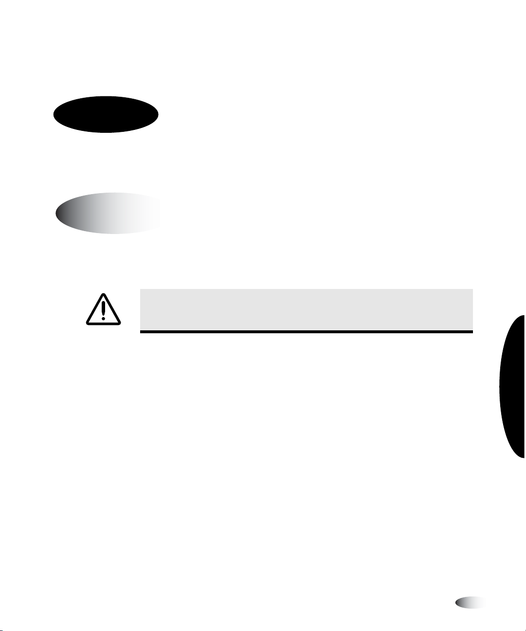
4. Open the Smart Card/Zip drive access door at the lower right
front of the imager and make sure that the Smart Card is fully
seated in its slot.
1-2 Setting Up the Imager
Page 30
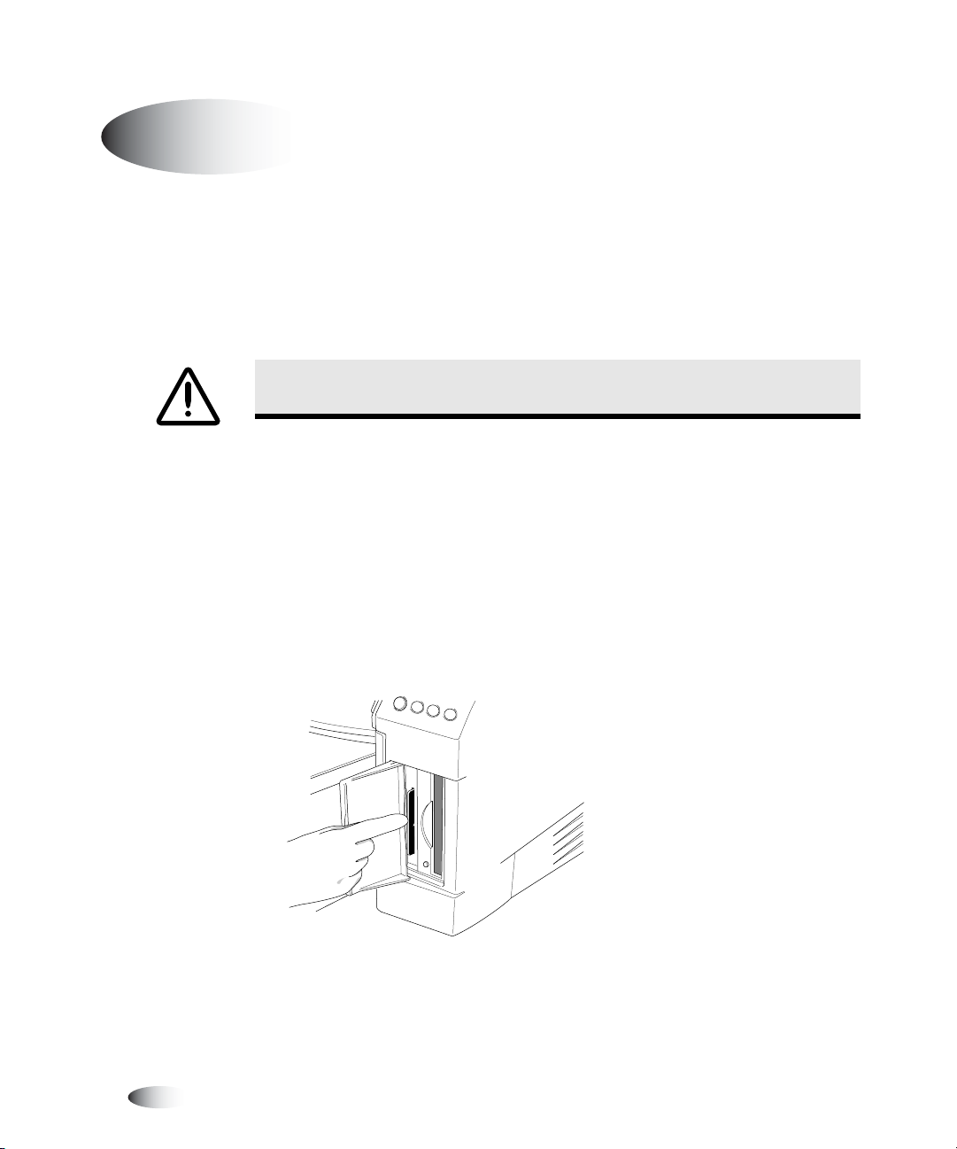
5. Retrieve the power cord from the Accessories box and plug its
right-angle connector into the power connection at the rear of
the imager.
This equipment has been type tested and found to comply with the requirements in part 15 of FCC rules and Canadian Department of communications for a Class B
computing device. See instruction manual. Operation in a residential area may cause unacceptable interference to radio and TV reception requiring the operator to
take whatever steps are necessary to correct the interference.
Le prsent appareil num rique n' met pas de bruits radio lectr iques d passant les limites applicables aux appareils numr iques de la Classe B prescrites dans le
Rglement sur le brouillage r adio lectr ique dict par le minist re des Comm unications du Canada.
This product is in conformity with the requirements of EC Council directive 93/42/EEC on the approximation of the laws of the Member States relating to medical
devices. This product satisfies the Class B limits of EN 55011 and CISPR 11.
CODONICS, INC.
17991 ENGLEWOOD DR.
MEDICAL ELECTRICAL EQUIPMENT
MIDDLEBURG HTS., OH 44130 U.S.A.
UL.2601-1, CAN/CSA C22.2 NO.601.1
MADE IN THE U.S.A.
Patents Pending, All Rights Reserved
AR: CEpartner4U, 2635 HL 33.NL
Tel: +31(0)6-516.536.26
31EB
COMPLIES WITH 21 CFR 1040.10 AND 1040.11
HORIZON MEDICAL PRINT IMAGER
EN 60601-1
100-120V , 50-60Hz, 6.0A
230
V , 50-60Hz, 3.0A
6. Plug the other end of the power cord into the UPS or electrical
outlet.
Horizon Starter Manual 1-3
Setting Up the Imager
Page 31

7. Open the top cover by pressing any of the green releases.
Left release
Master release
8. Remove any packing material inside the imager.
Right release
1-4 Setting Up the Imager
Page 32

9. Using a print head cleaning wipe included in the Accessory box,
gently clean the imager basement of any debris.
CAUTION
basement will damage the printed side of
Hide track
Cassettes
Cross-Section of Imager, Showing Location of Hide Track and Basement
(with receive trays and cassettes installed)
Do not scratch or nick the sheet metal. Scratches and nicks in the
ChromaVista
Receive trays
Basement
sheets.
Setting Up the Imager
3
10. Remove the receive trays from their box.
11. Using a platen roller wipe included in the Accessory box, clean
the receive trays of any dust or debris.
NOTE:
Save the imager box and all packing material. You must reinsert any packing
material and use the original box to ship the imager. Refer to “Preparing the Imager for
Shipment” on page 1-15 for more information.
Horizon Starter Manual 1-5
Page 33
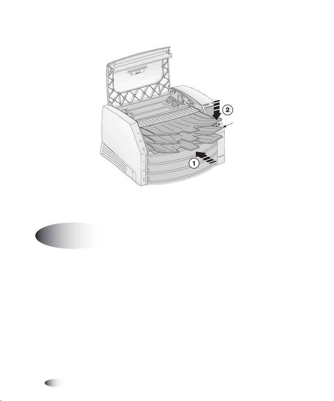
12. Place the receive trays into the imager.
13. Close the top cover.
Receive trays
Connecting the Ethernet Cable
The Horizon imager supports the following network cables and
hubs:
1-6 Setting Up the Imager
Page 34

•
Category 5, RJ-45 [also referred to as unshielded twisted pair
(UTP)] network patch cables and crossover cables
•
10/100 Base-T Ethernet hubs
8
To connect the
Ethernet cable
to the imager
CAUTION
Make sure that the imager is powered off before connecting the Ethernet
cable. For information about powering the imager on and off, refer to “Powering the
Imager On and Off” on page 2-3.
1. Locate the Ethernet cable jack at the back of the imager and
insert the Ethernet cable.
Network
connector
NETWORK
E
L
ONSO
C
S
UP
This equipment has been type tested and found to comply with the requirements in part 15 of FCC rules and Canadian Department of communications for a Class B
computing device. See instruction manual. Operation in a residential area may cause unacceptable interference to radio and TV reception requiring the operator to
take whatever steps are necessary to correct the interference.
Le prsent appareil num rique n' met pas de bruits radio lectr iques d passant les limites applicables aux appareils numr iques de la Classe B prescrites dans le
Rglement sur le brouillage r adio lectr ique dict par le minist re des Comm unications du Canada.
This product is in conformity with the requirements of EC Council directive 93/42/EEC on the approximation of the laws of the Member States relating to medical
devices. This product satisfies the Class B limits of EN 55011 and CISPR 11.
CODONICS, INC.
17991 ENGLEWOOD DR.
MEDICAL ELECTRICAL EQUIPMENT
MIDDLEBURG HTS., OH 44130 U.S.A.
UL.2601-1, CAN/CSA C22.2 NO.601.1
MADE IN THE U.S.A.
Patents Pending, All Rights Reserved
AR: CEpartner4U, 2635 HL 33.NL
Tel: +31(0)6-516.536.26
31EB
COMPLIES WITH 21 CFR 1040.10 AND 1040.11
EN 60601-1
HORIZON MEDICAL PRINT IMAGER
100-120V , 50-60Hz, 6.0A
V , 50-60Hz, 3.0A
230
530-040-004 REV 02
Setting Up the Imager
CAUTION
Do not touch any of the connector pins.
2. Connect the other end of the Ethernet cable to the Ethernet hub
or to the workstation’s Ethernet jack.
Horizon Starter Manual 1-7
Page 35

NOTE:
When connecting the imager to only one workstation without the use of a hub, you
3
must use a special Ethernet cable, called a
connect the imager and the single workstation using two standard Ethernet patch cables and
a hub. This would allow for future expansion of the network.
crossover cable
. Optionally, you could still
Powering On the Imager—First Time
8
To power on
the imager
1. Press the power rocker switch to the 1 (on) position.
Power rocker switch
1-8 Setting Up the Imager
Page 36

3
2. Press the (power) key at the control panel.
NOTE:
Always use the key at the control panel to power on/off the imager. The power
rocker switch at the back of the imager should always be in the 1 (on) position, unless the
imager is being serviced or moved.
The control panel display shows startup messages as the imager
initializes. When the Status screen displays (shown below), the
imager is ready to receive images.
Supply
1: No cassette
2: No cassette
3: No cassette
Status OK
X
No sheets queued
Cleaning the Platen Roller
Clean the platen roller after powering the imager on for the first
time. Refer to “Cleaning the Thermal Print Head and Platen Roller”
on page 7-3.
Horizon Starter Manual 1-9
Setting Up the Imager
Page 37

Network Settings—Simple Network
This topic explains how to add the imager to a simple network. For
Horizon
3
adding the imager to a complex network, refer to the
Imager Technical Manual
NOTE:
If your network is managed by a network administrator or an information technology
(IT) department, it would be considered a complex network. You should have the
responsible person perform any network-related administrative tasks.
By
simple network
, we mean a local-area network (LAN) that is
.
connected to another LAN or wide-area network (WAN).
A simple network typically comprises several devices connected by
Ethernet UTP cable through an Ethernet hub. It could also be
simpler yet—a workstation or imaging device connected directly to
the Horizon imager using an Ethernet crossover cable.
not
View workstation
Simple Network with Ethernet Hub
1-10 Setting Up the Imager
Imaging device
Horizon imager
Ethernet hub
Page 38

Ethernet crossover cable
3
View workstation
Simple Network with Ethernet Crossover Cable
Horizon imager
In addition to the physical cabling connection, you must define an
IP (Internet Protocol) address for the imager.
Specifying the Imager’s IP Address
The required IP address uniquely identifies the imager on the
network.
Determining an IP Address
Make sure that device IP addresses within this network are unique.
NOTE:
If devices on this network do have to communicate with devices on other networks,
it is part of a complex network. For more information about configuring the Horizon imager
in a complex network, refer to the
Horizon Imager Technical Manual
IP addresses have the format x.x.x.x, where x is a value from 0 to
255. One series of IP addresses, 192.168.x.
x,
internet convention for self-contained networks. You assign the last
two parts in the address. So, you might assign the IP addresses as
follows:
.
has been reserved by
Setting Up the Imager
•
192.168.1.200
•
192.168.1.201
•
192.168.1.202
•
192.168.1.203
And so on.
to the Horizon imager
to an image viewing workstation on the network
to a second workstation
to an imaging device
Horizon Starter Manual 1-11
Page 39

3
3
3
Specifying the Imager’s IP Address at the Control Panel
NOTE:
For a simple network, you will only need to define the imager’s base IP address. You
can leave all other network settings for the imager at their default values.
NOTE:
For instructions on how to use the imager’s control panel and menus, refer to
Chapter 2.
NOTE:
After entering the base IP address, note that the imager will reboot once you exit the
menus so that the software can be properly updated with the new value.
8
To specify the
imager’s IP
address
1. At the imager’s control panel, press and hold the key, and
while holding it press the key.
MENU
W
The Main Menu with administrative options displays.
2. Use the and keys to move the selector arrow to
Settings
Load/Remove Ribbon...
Custom Job Settings...
Utilities...
Test Prints...
Print From Zip Disk...
Feature Management...
X
Network Settings...
Configure TCP/IP network
settings
S
.
T
Menu
Press MENU to exit menus
Network
1-12 Setting Up the Imager
Page 40

3. With the
Network Settings
option selected, press the key.
The Network Settings menu displays. Note that the current
settings are displayed in square brackets.
Network Settings
Network Settings
Speed [Auto Sense]...
XAddresses...
Reset Network Settings
Set network addresses of this
Imager.
Press MENU to exit menus
ENTER
3
4. Select the
Addresses
option, then press the key.
ENTER
The Network Addresses menu displays. Note that bold square
change
brackets are displayed around the first IP address octet
value of the Base IP Address. The bracketed portion of the
address is the portion that can currently be changed.
Network Addresses
Base IP Address:
[0].0.0.0
Gateway:
0.0.0.0
Subnet Mask:
255.255.255.0
Number of IP Addresses: 1
Set base IP address
Old value: 0.0.0.0
UP/DOWN to alter octet, LEFT/RIGHT
to change octets
Press MENU to exit menus
NOTE:
The Horizon imager can have more than one IP address assigned to it. For more
information about assigning multiple IP addresses, refer to the
Manual
.
Horizon Imager Technical
Setting Up the Imager
Horizon Starter Manual 1-13
Page 41

5. To change the first octet, press the or key until the
S
T
number you want is displayed.
Hold these keys to cycle through numbers.
3
3
6. To select the next octet, press the key. (Press the key to
X W
return to the previous octet.)
7. Repeat steps 5 and 6 until all four octets in the Base IP Address
have been defined. To save, press the key.
NOTE:
To exit the Network Addresses menu without saving your changes, press the
CANCEL
key. The previous menu in the hierarchy displays.
8. Press the or key to leave the Network Settings menu.
CANCEL
W
ENTER
A message states that the imager will automatically reboot when
you press the key to exit the Main Menu.
9. Press the key to acknowledge the message.
MENU
ENTER
10. When you are finished specifying the IP address and want to
exit the Main Menu, press the key.
MENU
Because the base IP address was defined, the imager reboots so
that it can be identified properly on the network.
NOTE:
You can reset the network settings to their default values at any time by selecting
Reset Network Settings
the
option in the Network Settings menu.
Specifying IP Addresses for Other Devices
on the Network
Just as you did for the Horizon imager, you must specify the IP
addresses for each of the other devices on the network. Refer to the
documentation or online help that comes with the device for
specific instructions.
For more information about IP addressing conventions, refer to the
Horizon Imager Technical Manual
1-14 Setting Up the Imager
.
Page 42

Loading Media
After setting the imager’s IP address, you can load media cassettes
and, optionally, load a ribbon to support color prints. For more
information about how to load media, refer to “Inserting or
Changing Cassettes” on page 3-4 and “Changing the Ribbon
(ChromaVista)” on page 3-7.
Preparing the Imager for Shipment
If you have to ship the imager for any reason, you must use the
original imager box and packing materials. If you do not have the
original box and packing materials, contact your Codonics
representative.
8
To prepare the
imager for
shipment
3
1. If a ribbon is in the imager, remove it. For more information,
refer to “Changing the Ribbon (ChromaVista)” on page 3-7.
2. Make sure the top cover is closed and the receive trays are
inserted.
NOTE:
The top cover must be closed
print head to park. If either the top cover is open or the receive trays are not inserted, the
imager will display a message indicating that it cannot be shut down until the condition is
corrected.
and
the receive trays must be inserted for the thermal
3. Power off the imager. For more information, refer to “Powering
Off the Imager” on page 2-7.
4. Remove the receive trays.
Horizon Starter Manual 1-15
Setting Up the Imager
Page 43

5. Open the top cover by pressing any of the green releases.
Left release
Master release
Right release
6. Make sure that the thermal print head has parked. The thermal
print head should be secure with no wobble.
Make sure thermal
print head is secure
and does not wobble
1-16 Setting Up the Imager
Thermal print head
Page 44

CAUTION
steps 2 and 3 to properly power off the imager so that it does park.
If the thermal print head is not parked, power on the imager, then repeat
7. Look down into the imager just in front of the thermal print
head and make sure that the ribbon carriage is fully down to the
bottom of the imager. (The ribbon carriage should have lowered
during power off.)
Thermal print head
3
Ribbon carriage
at bottom of imager
Cross-Section View of Imager
NOTE:
If the ribbon carriage is not fully down, you can use the foam stabilizer to push it
down. The stabilizer is shown in the first panel of the repacking illustration on the box insert.
The ribbon carriage does not move easily, but it is safe to apply moderate pressure to force
it all the way down.
CAUTION
damage the carriage.
Push the ribbon carriage down slowly. Forcing it down too quickly may
8. Replace the packing materials into the imager, close the top
cover, and repack the imager into its original box. Refer to the
box insert for illustrated instructions.
Horizon Starter Manual 1-17
Setting Up the Imager
Page 45

Page 46
2
Basic Imager Operations
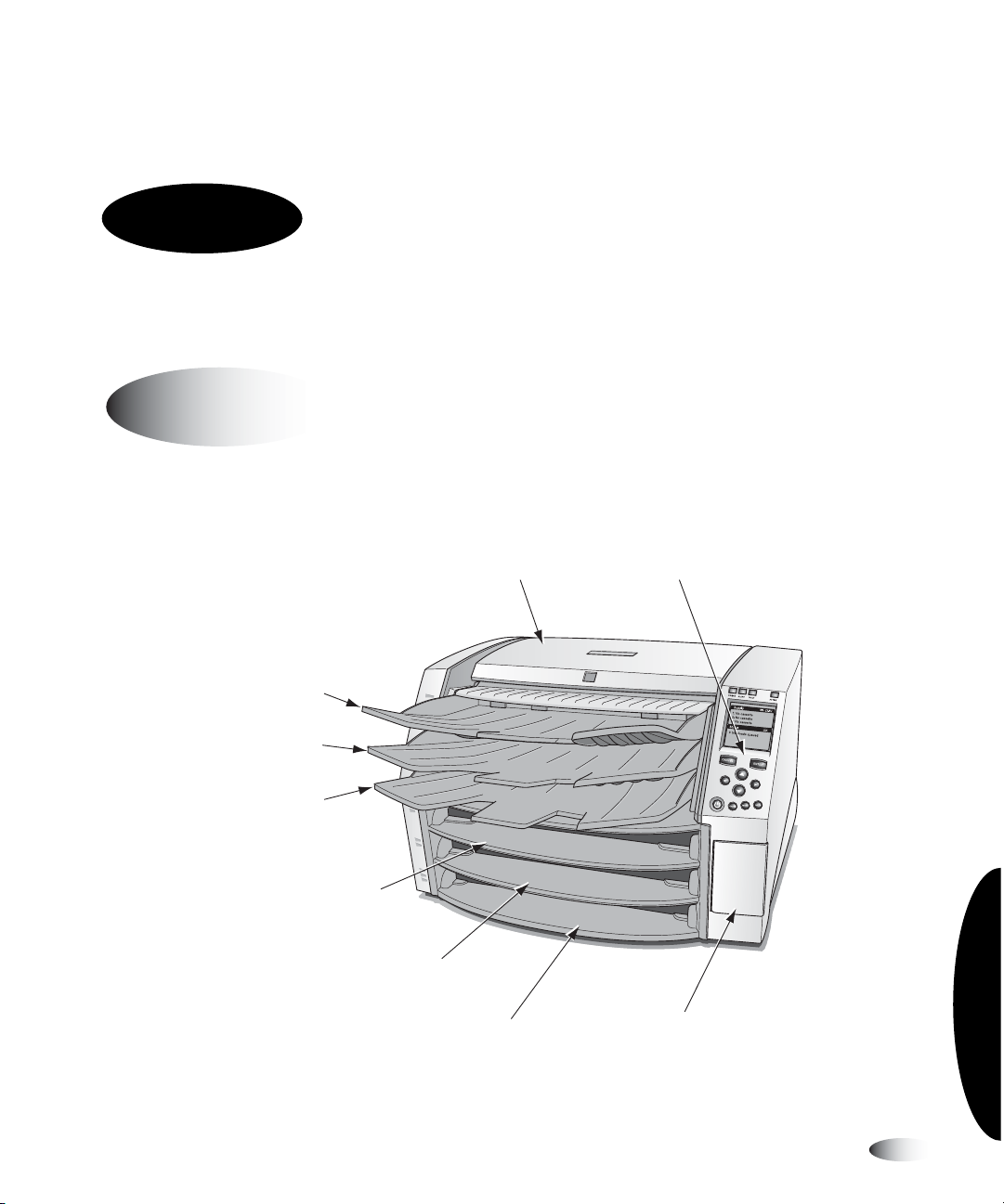
Horizon Imager Components
The following illustrations show the names and locations of the
main imager components.
Top cover Control panel
Receive tray 1
Receive tray 2
Receive tray 3
Supply slot 1
Names and Locations of the Imager’s Main Components—Front
Supply slot 2
Supply slot 3
Basic Imager Operations
Smart Card/
Zip drive panel door
Horizon Starter Manual 2-1
Page 47
KCONSOLE
R
O
W
T
E
N
S
P
U
This equipment has been type tested and found to comply with the requirements in part 15 of FCC rules and Canadian Department of communications for a Class B
computing device. See instruction manual. Operation in a residential area may cause unacceptable interference to radio and TV reception requiring the operator to
take whatever steps are necessary to correct the interference.
Le pr sent appareil num rique n' met pas de bruits radio lectr iques d passant les limites applicables aux appareils num r iques de la Classe B prescrites dans le
R glement sur le brouillage radio lectr ique dict par le minist re des Comm unications du Canada.
This product is in conformity with the requirements of EC Council directive 93/42/EEC on the approximation of the laws of the Member States relating to medical
devices. This product satisfies the Class B limits of EN 55011 and CISPR 11.
CODONICS, INC.
17991 ENGLEWOOD DR.
MEDICAL ELECTRICAL EQUIPMENT
MIDDLEBURG HTS., OH 44130 U.S.A.
UL.2601-1, CAN/CSA C22.2 NO.601.1
MADE IN THE U.S.A.
Patents Pending, All Rights Reserved
AR: CEpartner4U, 2635 HL 33.NL
Tel: +31(0)6-516.536.26
31EB
COMPLIES WITH 21 CFR 1040.10 AND 1040.11
HORIZON MEDICAL PRINT IMAGER
EN 60601-1
100-120V , 50-60Hz, 6.0A
V , 50-60Hz, 3.0A
230
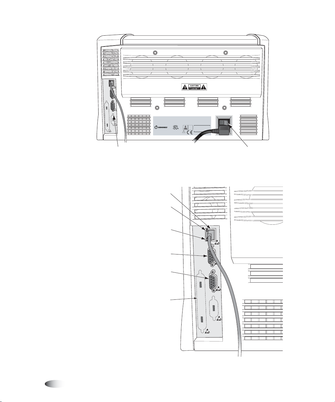
Power rocker switchConnectors
Names and Locations of the Imager’s Main Components—Rear
Network connector
Speed indicator:
On = 100 Mbps
Off = 10 Mbps
(for connection to UPS serial
Rear Connectors
2-2 Basic Imager Operations
Activity indicator:
On = Link
Flashing = Activity
Off = No link
Console
(Service only)
UPS
control cable)
Expansion slot
(for future use)
NETWORK
CONSOLE
UPS
Page 48

Powering the Imager On and Off
Powering On the Imager
8
To power on
the imager
3
Press the (power) key at the control panel.
The startup process takes 2 to 3 minutes. When the Status screen
displays, the imager is ready to receive images.
NOTE:
The
Horizon Imager Technical Manual
more detailed imager status information.
includes information about how to obtain
Horizon Starter Manual 2-3
Basic Imager Operations
Page 49

Observing the Imager’s Operating Status
in the Status Screen
The Status screen allows you to observe the imager status. The top
portion of the screen—the Supply window—displays the status of
the three supply cassettes and whether a color ribbon is installed.
The bottom portion of the screen—the Status window—displays
printing status messages and the imager’s operational state.
Supply window: Indicates
status of supply slots
Indicates that color ribbon
is installed and its status
Supply CMY
1: 8X10 DV Blue 53
2: A CV Paper 50
3: 14X17 DV Blue 76
Status OK
X
Sheets queued: 3
Status window: status
messages displayed here
When activity occurs, each
supply entry toggles with
activity status related to
cassette (processing, printing,
calibrating, media jam)
Number of sheets left in
cassette
Operational state (OK,
ALERT, or FAULT)
To get additional information about the currently selected status
message, press the key.
HELP
2-4 Basic Imager Operations
Page 50

Common Cassette Status Messages
The following table lists common cassette-related status messages.
Table 2-1. Cassette Status Messages
Message Explanation
Calibrating The imager is performing a calibration.
When performing a film calibration (when a DirectVista
grayscale film cassette is first inserted, or initiated manually
through the Main Menu), the “calibrating” message toggles
with supply information.
Checking cassette The imager is reading the supply cassette’s barcode, or waiting
to read the barcode (for example, if the top cover is open, the
barcode will not be read).
Media size, type,
and count
No cassette No cassette is loaded in the supply slot.
Printing The imager is printing from the indicated cassette.
Cleaning The imager is cleaning the picking system.
Indicates the type, size, and sheet count of the media cassette
inserted in the corresponding supply slot. For example,
14x17 DV Blue 53, indicating the cassette currently has 53
sheets of 14 x 17-in. DirectVista blue film.
Basic Imager Operations
Horizon Starter Manual 2-5
Page 51

Color Ribbon Status
The following table lists the color ribbon status indications.
Table 2-2. Color Ribbon Status Indications
Indication Explanation
Blank; the imager does not support ChromaVista color media.
CMY
OUT
WAIT
ERR
Ribbon loaded. Ribbon type indicated (for example, CMY for
cyan/magenta/yellow).
Ribbon loaded but the ribbon is spent.
Ribbon not loaded (and the imager does support ChromaVista
color media).
State of ribbon being determined.
Ribbon loaded but in an error condition.
2-6 Basic Imager Operations
Page 52

Powering Off the Imager
8
To power off
the imager
3
1. Press the (power) key at the control panel.
The Power menu displays.
Power
X
Power Off
Reboot
NOTE:
To cancel the power off , press the key again or the key.
2. Select the
Power Off
option.
CANCEL
Shutdown messages are displayed. When the shutdown
operation is complete, the imager powers off.
3
NOTE:
Always use the
rocker switch at the back of the imager should always be in the 1 (on) position, unless the
imager is being serviced or moved.
CAUTION
saved and will finish printing once the imager is powered on again. However, if the
imager is powered off using the rocker switch in the back or power is interrupted,
queued jobs may be lost.
If the imager is powered off using the key, unprinted queued jobs are
key at the control panel to power on/off the imager. The power
Horizon Starter Manual 2-7
Basic Imager Operations
Page 53

Understanding the Control Panel
Indicators
Refer to page 2-9
Display
Refer to page 2-10
Power key
Refer to page 2-3
2-8 Basic Imager Operations
Keys
Page 54

Control Panel Indicators
The following table describes the control panel indicators.
Table 2-3. Control Panel Indicators
Indicator Description
ONLINE (green) Indicates when imager is online (lit) or offline (off):
• When online, printing is enabled.
• When offline, printing is paused.
In both cases, the imager will continue to receive and
process print jobs.
ALERT (yellow) When lit, indicates a condition that requires operator
attention, but printing can continue.
An example of an alert condition is a queued job that
requires a supply cassette that is currently not loaded or
is empty, but other cassettes are not empty.
AULT (red) Indicates an imager fault condition that prevents the
F
imager from printing any job and requires operator
intervention. For example:
• A sheet is jammed
• No supply cassettes are loaded
• All supply cassettes are empty
ACTIVE (green) Has the following states:
• On: The imager is powered on but idle.
• Off: The imager is powered off.
• Flashing: The imager is actively receiving, processing,
or printing jobs; or powering on, off, or rebooting. If
jobs are paused, the A
CTIVE indicator will not flash.
Horizon Starter Manual 2-9
Basic Imager Operations
Page 55

Alert and Fault Messages and the Fault
Tone
When the imager needs attention or an error occurs, the
FAULT
indicator lights. Messages are displayed in the Status screen
ALERT
or
to help you respond to the condition.
If operator intervention is required, a Fault tone sounds. To stop the
Fault tone, press any control panel key.
For more information about alert and fault messages and how to
respond to them, refer to Chapter 9.
Control Panel Display
Main Menu
When the key is pressed, the
Menu to perform basic and frequently used imager operations.
use the and keys to
MENU
Selector arrow;
S
scroll the selector arrow
T
through the list.
Main Menu
XOpen Top Cover...
displays. Use the Main
Default Media...
Load/Remove Ribbon...
Utilities...
Test Prints...
Menu
2-10 Basic Imager Operations
Help message area
Access Imager internals to clean or
to change ribbon
Press MENU to exit menus
Page 56

If you press the key and, while holding it, press the key,
W
MENU
the Status screen shows additional administrative options in the
menus. You use these additional options to perform system
maintenance and setup tasks.
8
To exit the
Menu screens
Menu
Default User Settings...
Default Media...
XOpen Top Cover...
Load/Remove Ribbon...
Custom Job Settings...
Utilities...
Test Prints...
Print From Zip Disk...
Access Imager internals to clean
or to change ribbon.
Press MENU to exit menus
When finished, press the key. The Status screen is
MENU
Scroll indicator displays
when there are more menu
items available than can be
displayed at one time.
Black portion of scroll
indicator indicates where
the selected item is within
the complete list.
Use the and keys
to scroll the selector arrow
through the list.
S
T
displayed.
Horizon Starter Manual 2-11
Basic Imager Operations
Page 57

Page 58
3
Overview
Media Handling and Storage
Media Handling and
Storage
Supply Slots and Cassettes
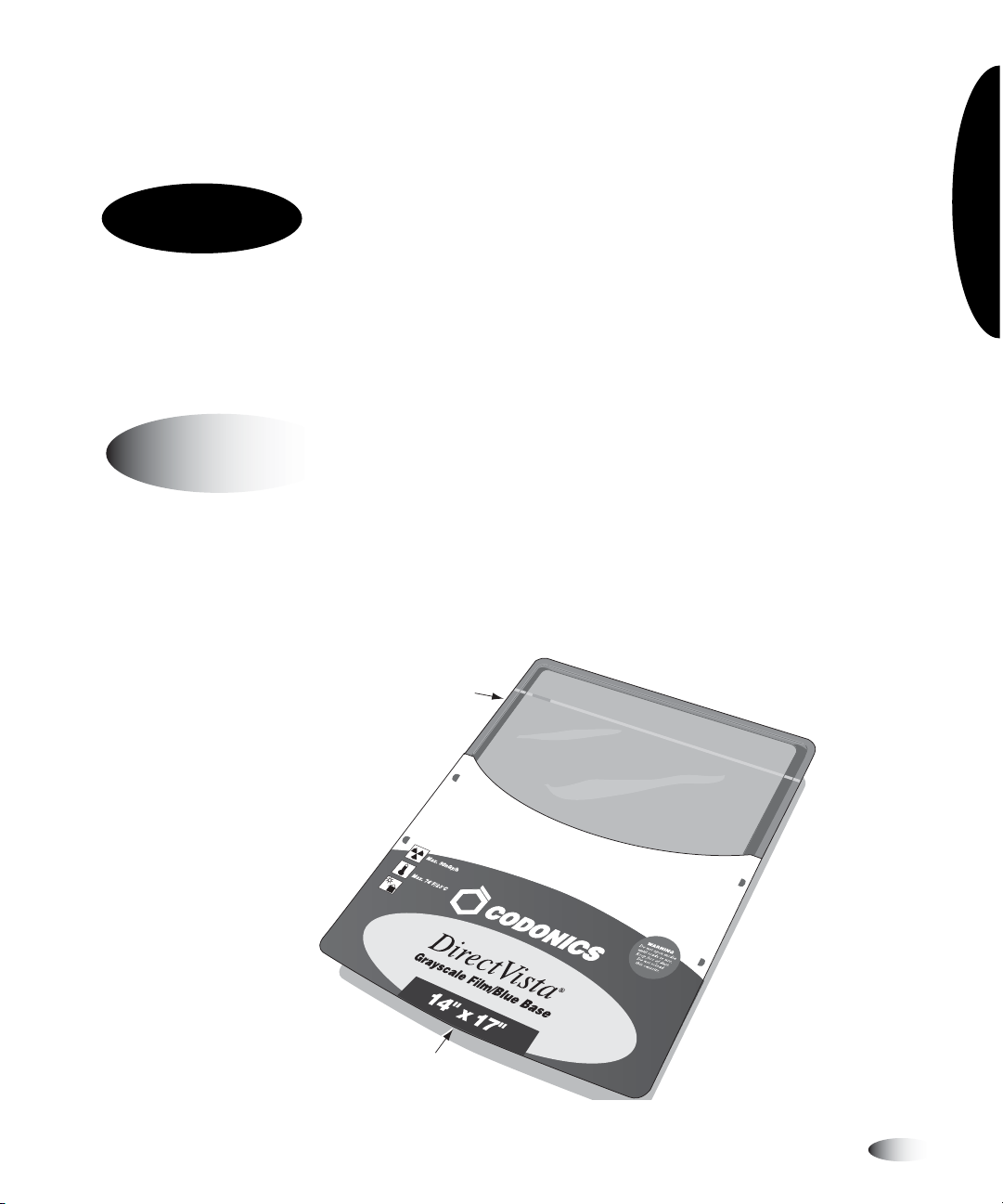
Media used with the Horizon imager is prepackaged in
factory-sealed, disposable cassettes.
Barcode
(on side)
Cassette cover:
Do not remove
Horizon Starter Manual 3-1
Page 59

Each cassette contains a barcode that allows the imager to track
how many sheets remain in the cassette (this count will be
inaccurate if sheets have been manually added or removed, or the
cassette has been moved to a different imager).
In addition to the barcode itself, the cassette’s lot number and “Use
by” date are printed on the barcode label.
All cassettes can be loaded into any of the imager’s three supply
slots. By default, the printer ejects completed prints to the
corresponding receive tray.
CAUTION
or other unapproved media as damage, improper operation, or malfunction may
result. For information about the approved Codonics media types and sizes, and how
to order cassettes, refer to “Ordering Media” on page 3-10.
CAUTION
The cassette’s barcode information is essential for ensuring diagnostic image quality.
Compromising the cassette in any way jeopardizes the quality and reliability of the
imager.
3-2 Media Handling and Storage
Use only Codonics media. Do not use plain paper, office transparencies,
Do not refill a cassette. Do not tamper with or remove the barcode label.
Page 60

Viewing the Status of a Supply Slot
The Status screen shows the status of each supply slot, including
media type, size, and number of sheets remaining.
Supply CMY
1: 8X10 DV Blue 53
2: A CV Paper 100
3: 14X17 DV Blue 76
Status OK
X
3 sheets queued
Media Handling and Storage
Horizon Starter Manual 3-3
Page 61

Inserting or Changing Cassettes
8
To change a
supply
cassette
1. Press the key, and wait until the
PAUSE
ONLINE
indicator turns off
and the Status screen indicates that the imager is paused.
If a sheet is currently being printed, the sheet will complete
printing before the imager enters the Paused state. While
paused, the imager can still receive and process jobs.
CAUTION
could affect the image quality of the printed sheet or cause a jam. Always pause the
imager first.
Do not remove or insert a cassette while a sheet is being printed, or you
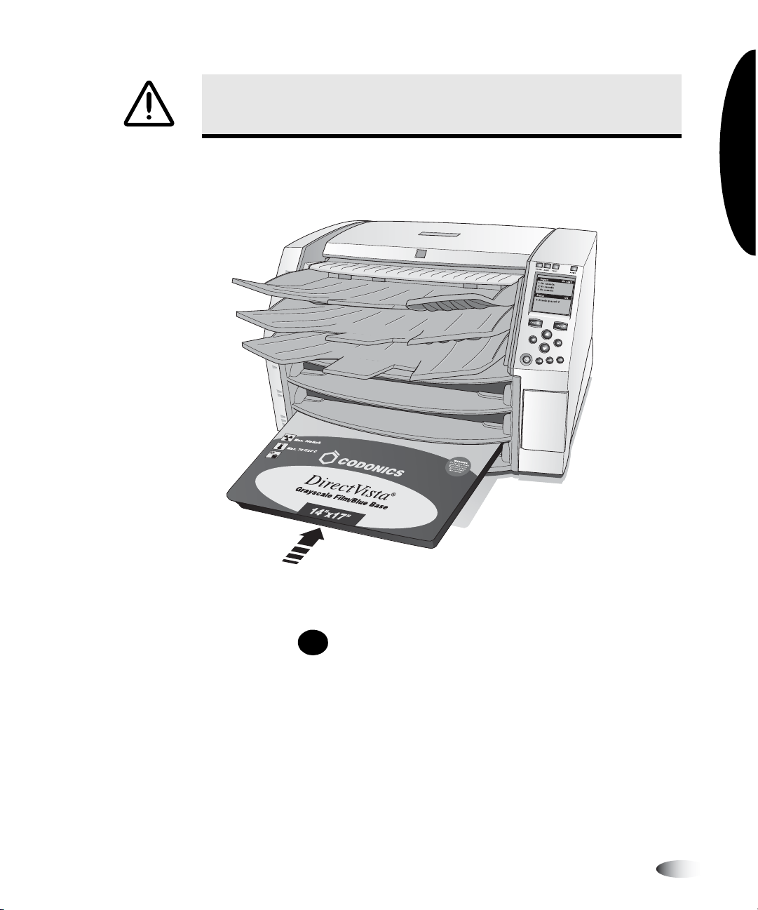
2. Remove the cassette if one is currently in the supply slot you
want to use—lift the cassette up slightly and slide it from the
supply slot.
3. If inserting a new cassette, remove the clear wrapping from the
cassette. Use the pull strip to tear the clear wrapping.
Seam
3-4 Media Handling and Storage
Page 62
CAUTION
and other contaminants. Always hold and store the cassette with the open side up to
prevent the sheets from falling out.
Do not remove the printed cassette cover; it protects the media from dust
4. Insert the new cassette into the supply slot, with the cassette
label facing you and the barcode label to the left.
Media Handling and Storage
5. Slide the cassette into the supply slot until you feel the cassette
settle into the retaining detent.
6. Press the key to resume printing.
PAUSE
Horizon Starter Manual 3-5
Page 63

Handling and Storing Media
For best results, refer to the storage and handling instructions that
come with the media.
Break-Off Leaders (ChromaVista Only)
8
To remove the
break-off
leader
ChromaVista
and bottom to allow edge-to-edge printing:
On a completed print, bend the leader at the perforation line
fully one way, then fully the other way. The leader will break
away from the sheet.
color paper and film have break-off leaders at the top
3-6 Media Handling and Storage
Page 64

Changing the Ribbon (ChromaVista)
When the ribbon on the ribbon spools has been consumed and
needs to be changed:
•
The imager enters the Alert state.
•
A message indicating that a new ribbon needs to be loaded is
displayed in the Status window.
Media Handling and Storage
8
To change the
color ribbon
1. Press the key.
MENU
The Main Menu displays.
2. Select the
Load/Remove Ribbon
menu option.
After selecting this option:
•
The imager pauses, first completing the sheet if one is
currently printing.
•
The ribbon supply spool inside the imager rises.
•
After up to a minute to allow the thermal print head to cool,
the imager cover pops partially open.
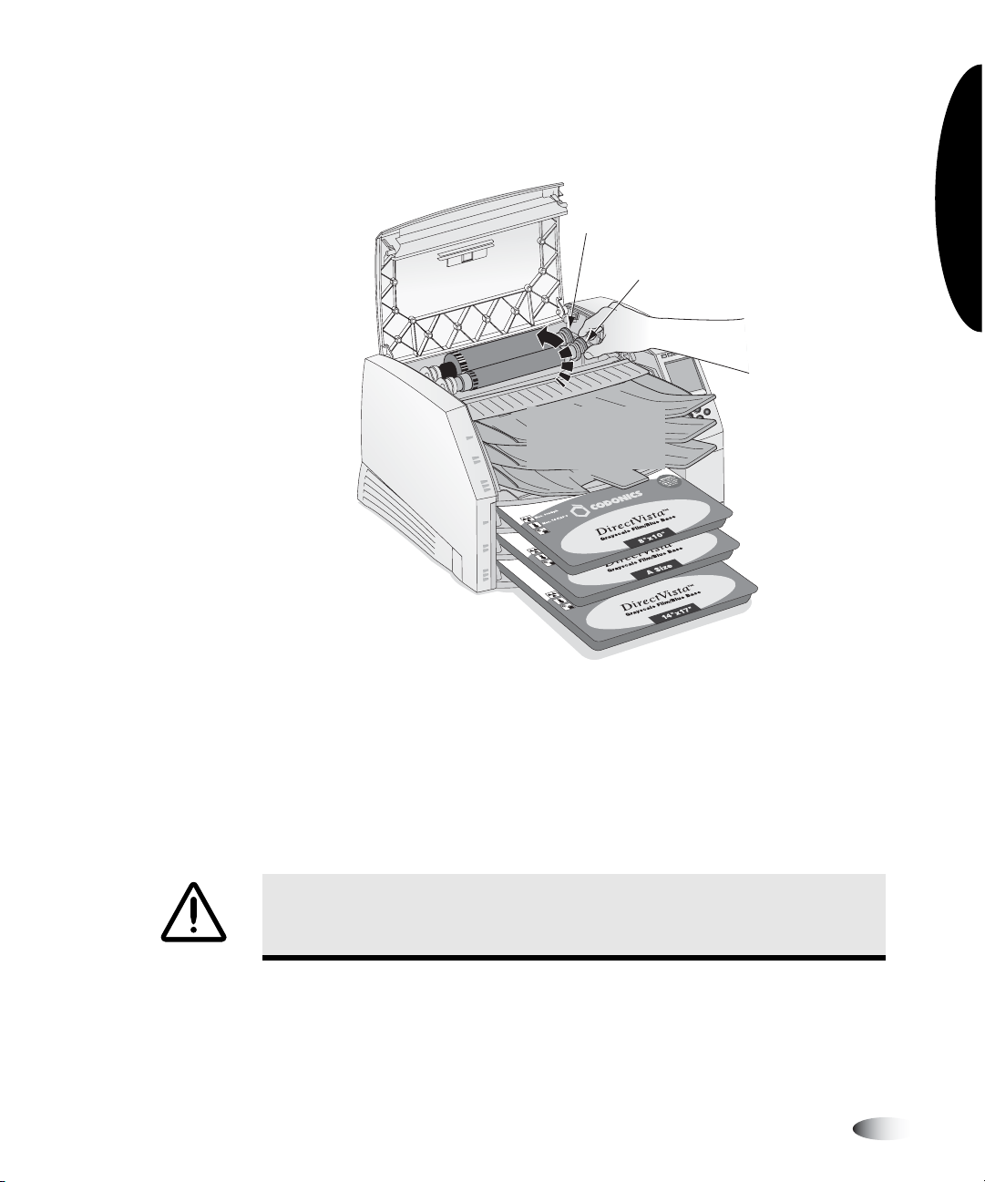
3. Lift the cover all the way open, and locate the ribbon spools.
WARNING With the imager cover open, touch only those internal components
that are colored green (except for the pick tires, refer to the figure on page xx).
Remove rings, ties, jewelry, and other items, and tie back hair, so that they do
not fall into or get caught in the imager.
Horizon Starter Manual 3-7
Page 65

4. Remove the old ribbon, as shown in the following figure.
Spring-loaded
spindles
5. Load the new ribbon, as shown in the following figure.
Spring-loaded
spindles
3-8 Media Handling and Storage
Black (Supply)
Gray (Take-up)
Page 66
6. To take up any ribbon slack, rotate the top of the take-up spool’s
wheel (that is, the front wheel) towards the back of the imager,
as shown in the following figure.
Supply spool wheel
(Do not use this wheel)
Take-up spool wheel
Rotate take-up
spool toward
back
Media Handling and Storage
3
NOTE:
Do not use the supply spool (rear) wheel to take up ribbon slack. This would cause
spent ribbon to be reused.
7. When you are finished changing the ribbon, close the top cover.
After several seconds, the imager will leave the paused state and
resume printing.
CAUTION
using that ribbon. If you are required to ensure patient confidentiality and privacy, the
ribbon should be destroyed.
Used ribbon retains the negative of the color images that were printed
Horizon Starter Manual 3-9
Page 67

Ordering Media
The Horizon imager supports a variety of paper and film for both
grayscale and color prints. Not all Horizon imager configurations
support all media types and sizes. If your Horizon imager does not
support the media type and/or size you want to use, contact your
Codonics representative.
The following table shows the currently supported media size/type
combinations:
Media Type Size Catalog Number
3
DirectVista Paper A (8.5 x 11 in.)
A4 (210 x 297 mm)
11 x 14 in. (28 x 35 cm)
14 x 17 in. (35 x 43 cm)
DirectVista Film Blue 8 x 10 in.
11 x 14 in.
14 x 17 in.
DirectVista Film Clear 8 x 10 in.
11 x 14 in.
14 x 17 in.
ChromaVista Paper A
A4
ChromaVista Film A
A4
NOTE:
Some of the media type/size combinations listed here may not currently be
available.
A-DVP
A4-DVP
1114-DVP
1417-DVP
810-DVB
1114-DVB
1417-DVB
810-DVC
1114-DVC
1417-DVC
A-CVP
A4-CVP
A-CVC
A4-CVC
3-10 Media Handling and Storage
Page 68

4
Printing from DICOM
Applications
The printing procedures covered in this chapter assume that the
DICOM support option is installed in your Horizon imager and that
you are sending print jobs from a DICOM application.
NOTE:
If you are running DICOM Lite on the imager and see connection errors at the
3
Introduction to DICOM
console or workstation from which you are sending print jobs, you may require full DICOM.
Contact Codonics technical support for assistance (refer to “Contacting Technical Support”
on page 9-20).
DICOM (Digital Imaging and COmmunications in Medicine) is the
industry standard for transferring images and other medical
information. The Horizon imager is DICOM Print Service
Class-compliant.
Printing from DICOM
Applications
For more information about DICOM, visit the official web site—
medical.nema.org
of the Radiological Society of North America, Inc. (
. Additional information is available at the web site
www.rsna.org
Horizon Starter Manual 4-1
).
Page 69

DICOM Conformance Statement
The Horizon imager conformance statement is available on the
Codonics web site (
www.codonics.com
). It can also be mailed or
faxed to you on request.
Configuring the DICOM Application
Your key operator or DICOM application vendor must configure the
DICOM application running on each imaging device printing to the
Horizon imager. This application is the
(SCU).
The imager is the
Print Service Class Provider.
Print Service Class User
Two pieces of information must be entered into the SCU: the
AE Title
, and the imager’s TCP port number. This information does
Called
not usually need to be configured at the Horizon imager.
The port number is
104
.
Common AE Titles are listed in the following table, which also
describes how they are used.
Called AE Title That Can Be Used Description
Print_SCP For standard print jobs.
mcmBracket and gcsBracket For printing bracketing sheets. For more
information, refer to the
User’s Manual
SpecialSlide For printing 35-mm slides. For more
information, refer to the
Technical Manual
The name of a Job Settings file
For printing using Job Settings files to
specify print job parameters. For a list of
Job Settings files provided with the
imager, refer to Appendix B.
.
Horizon Imager
Horizon Imager
.
Additional instructions about configuring DICOM are included in
the
Horizon Imager Technical Manual
.
4-2 Printing from DICOM Applications
Page 70

Sending a DICOM Print Job
How you select a Horizon imager as a destination, then send a print
job to it, is unique to your specific DICOM user application. For
details, refer to your key operator, DICOM user application vendor,
or the accompanying DICOM application documentation.
Specifying the Media Type and Size
Typically, you will set the media type and size to use for a given
print job from within the SCU DICOM application. However, if your
application does not support the correct size and type of media, you
have two options:
•
Use a System Job Settings file (listed in Appendix B) as the Called
AE Title. This will force the print job to the correct media size and
type. This is useful when only the media needs to be specified
via AE title.
•
Use a Custom Job Settings file that specifies the desired media
type/size. Custom Job Settings are most useful when several print
Job Settings must be controlled at the printer rather than at the
DICOM application.
Printing from DICOM
Applications
Using Job Settings Files with DICOM
Occasionally it is possible that there is a setting supported by the
Horizon imager that cannot be specified in your DICOM
application. Using the imager’s
around this limitation.
Job Settings
feature, you can work
Horizon Starter Manual 4-3
Page 71

The Horizon imager supports multiple Job Settings files, each of
which can define unique sets of sheet and image settings. A Job
Settings file can specify values for some or all sheet and image
settings. Settings include the media size and type, border color,
Dmax or Dmin, etc.
Categories of Job Settings
There are two categories of Job Settings:
•
System Job Settings.
preconfigured in the Horizon imager. They include a Job Setting
for each media type and size combination, for the three receive
trays, and for the three job priorities. For a complete list of the
system Job Settings files, refer to Appendix B.
•
Custom Job Settings.
site. They can be entered at the control panel, or by sending a
text file to the imager via FTP or LPR protocols. The procedures
for creating custom Job Settings files are described in the
Imager Technical Manual
These Job Settings files come
These Job Settings are created at the user
Horizon
.
Specifying a Job Settings File from a
DICOM User Application
Since the Horizon imager supports multiple Job Settings files, and
since those files are controlled by entering special Called AE Titles,
it is common to have several printer configurations set up in a
DICOM user application all pointing to a single Horizon imager. A
typical setup strategy creates separate profiles by media size and
type.
For example, the System Job Settings file that specifies
8 x 10 blue film is
film for a print job, the DICOM user application would use
8x10-dvfb
session with the Horizon imager. The DICOM user application may
also print color. Therefore, there will be a second printer setup on
the SCU with the AE title
4-4 Printing from DICOM Applications
as the Called AE Title when starting a Print Service Class
8x10-dvfb
a-cvp
. To specify
.
DirectVista
DirectVista 8 x 10 blue
Page 72

The Horizon imager also supports IP aliasing for systems that do
not support configuring more than one AE title per IP address. For
more information about how multiple IP addresses and DICOM
printing to the Horizon imager can be implemented, refer to the
Horizon Imager Technical Manual
.
Hierarchy of Settings Used by the Horizon
Imager
For DICOM print jobs, the Horizon imager uses the following
sequence to determine which sheet and image settings to use:
1. Specified Job Settings file (System or Custom).
2. For any sheet or image settings not specified in the Job Settings
file, look in the DICOM application settings.
3. For any sheet or image settings not specified in the Job Settings
file or DICOM application, uses the imager’s Default User
Settings.
For more information on the hierarchy of settings, refer to the
Horizon imager’s DICOM Conformance Statement, and to the
Horizon Imager Technical Manual
.
Printing from DICOM
Applications
Horizon Starter Manual 4-5
Page 73

Page 74

5
Printing from Windows
via PostScript
The printing procedures covered in this chapter assume that:
•
The PostScript support option is installed in your Horizon
imager.
•
The Horizon imager has been configured as a Windows desktop
printer on your workstation using the Horizon PostScript print
driver.
•
You are sending print jobs from a Windows (Windows 98, Me,
NT 4.0, 2000, or XP) application.
Printing from Windows
•
You are familiar, in general, with how to print from Windows
applications to a desktop printer.
Complete instructions for adding a Horizon imager as a desktop
printer are provided in the Horizon PostScript Driver Technical
Briefs, available in PDF format on the Horizon PostScript Drivers
CD-ROM.
For how to send PostScript files from a Macintosh, refer to the
Horizon Imager User’s Manual
For how to send PostScript files from UNIX or Linux, refer to the
Horizon Imager Technical Manual
.
.
Horizon Starter Manual 5-1
via PostScript
Page 75

Introduction to PostScript
PostScript printing technology was developed to provide consistent,
predictable printing from every major computer platform to any
printing device that supports it.
There have been three PostScript technologies released since its
inception—levels 1, 2, and, the most recent version, 3. The Horizon
imager supports all three levels.
Printing from Windows Applications
For detailed descriptions about print job, sheet, and image
parameters, refer to the
Notes About Changing PostScript Parameters
Horizon Imager Technical Manual
.
•
To avoid unpredictable results, change the defaults for only those
Horizon imager parameters listed in the
•
Settings changed via the Print dialog boxes will take precedence
over settings made at the imager.
5-2 Printing from Windows via PostScript
Technical Manual
.
Page 76

3
Changing Horizon PostScript Parameters—Windows 2000
and XP
NOTE:
This procedure assumes that the PostScript driver for the Horizon imager has
already been installed on the workstation. For more information, refer to the “Windows 2000
Driver Installation—Horizon” or “Windows XP Driver Installation—Horizon” Technical Brief.
Refer to the
Horizon User’s Manual
for information on other versions of Windows.
8
To change the
PostScript
parameters in
Windows 2000
and XP
1. Initiate the print job from the Windows application.
The Print dialog box displays.
2. Make sure that the Horizon imager is the selected printer.
3. Click the
Properties
button.
The Document Properties dialog box displays.
4. Click the
Advanced
button.
The Advanced Options dialog box displays.
Printing from Windows
via PostScript
Horizon Starter Manual 5-3
Page 77

5. Specify a Horizon media size and type combination from the
Paper Size
drop-down list. The Horizon media choices begin
with “HZ.”
6. To specify any of the other Horizon PostScript parameter
settings, scroll to the
Printer Features
list of parameters.
7. When you are done changing settings, click OK to save your
changes.
The settings you have saved will be in effect for the current
session of the application from which you are printing. If you
open a new session of the application or print from a different
application, the parameters revert to their default settings.
5-4 Printing from Windows via PostScript
Page 78

6
Default Print Job
Settings
Every print job has parameters associated with it that control how
the job is to be processed (for example, media size and type,
scaling, gamma, contrast, and so on).
The Horizon imager has a complete set of
media type/size, sheet, and image parameter of a print job. The
default settings can be viewed and changed through the control
panel. Default settings are applied when no other source, such as
the application or PostScript driver, supplies settings.
CAUTION
affect prints made by other users. Use Job Settings to avoid affecting other users.
Most DICOM applications support some, if not all, image and sheet
settings. Commonly-supported settings include Dmin, Dmax, and
trim lines.
Since any setting that appears in the control panel also appears in
the PostScript driver, it is usually more convenient to change
settings in the driver rather than in the control panel of the Horizon
Imager.
Refer to the
the print job parameters that can be changed.
Use caution when changing the imager default settings. Changes could
Horizon Imager Technical Manual
default settings
for a summary of
for every
Default Print Job Settings
Horizon Starter Manual 6-1
Page 79

Changing the Default Settings
Changing the Default Media Type and Size
One default media is specified for grayscale images, and one for
color images.
In practice, the PostScript driver or DICOM application will override
the Default Media setting. Default Media is available for the small
number of installations for which this is not the case.
When the imager receives a grayscale image, it prints the image to
the default grayscale media type and size, unless otherwise
specified. Likewise, when the imager receives a color image, it
prints the image to the default color media type and size.
8
To access the
Default Media
settings
S
MENU
ENTER
T
Default Media
Grayscale
or
option, then
Color
. A settings
1. Press the key.
2. Use the and keys to select the
press the key.
3. Select the desired image type—
menu option is displayed for each available media type
supported by your imager.
In addition to the settings options, the Default Media menu also
contains an option to reset the settings.
6-2 Default Print Job Settings
Page 80

Changing the Default User Settings
Default User Settings are located in the Administrative-level Main
Menu options.
8
To access the
Default User
Settings
1. Press the key and, while holding it, press the key.
2. Use the and keys to select the
then press the key. A settings menu option is displayed
W
S
T
ENTER
Default User Settings
MENU
option,
for each available media type supported by your imager.
In addition to the settings options, the Default User Settings menu
also contains an option to reset the settings.
CAUTION
being shipped (for example, to accommodate a special OEM configuration), resetting
to the factory defaults will not restore the “as shipped” settings. Instead, they will be
reset to the standard factory default values.
CAUTION
caution when changing default settings. Typically, it is better to specify sheet and
image parameter settings from the DICOM application or a PostScript printer’s
settings, or use a Job Settings file that contains the values you need. For information
about Job Settings files, refer to the
If the imager’s settings were changed from the factory defaults
Resetting to the factory defaults will affect prints made by other users. Use
Horizon Imager Technical Manual
prior
to
.
Horizon Starter Manual 6-3
Default Print Job Settings
Page 81

Page 82

7
Preventive Maintenance
Recommended Maintenance Schedule
The major cause of degraded imager performance and image output
quality is dirt and dust. Perform the following preventive
maintenance periodically.
Table 7-1. Recommended Maintenance Schedule
Maintenance Schedule Procedure on
Preventive Maintenance
Clean the thermal print head
and nosepiece
Clean the platen roller and
donor guide bar
Clean the pick tires • Every 1000 sheets, or more often in dirty
• Every 1000 sheets.
• If you notice image quality problems.
• If there is visible accumulation of debris.
• Every 1000 sheets.
• If you notice image quality problems.
• If there is visible accumulation of debris.
• If the imager has trouble printing.
conditions.
• If the imager has trouble picking sheets from a
cassette.
• If the imager has trouble printing.
page 7-3
page 7-3
page 7-7
Horizon Start Manual 7-1
Page 83

Table 7-1. Recommended Maintenance Schedule (cont.)
Maintenance Schedule Procedure on
Clean the barcode reader
window
Clean the cassette area, sheet
exit area, receive trays,
basement, and imager cabinet
with a platen roller wipe (refer
to “Horizon Cleaning Kits”
below)
Film calibration This calibration is done automatically whenever a
Every 12 months.
Every 2000 sheets to eliminate dust buildup and
prevent dirt from getting inside the imager.
new cassette is inserted for the first time. You can
also run this calibration manually at any time (for
example, if it has been more than three months since
the cassette was calibrated).
Horizon Cleaning Kits
The following cleaning kit is available to help you properly maintain
the Horizon imager:
•
The Horizon Cleaning Kit (catalog no. SP-00130) includes special
wipes that you will need to clean the thermal print head, platen
roller, pick tires, and other internal components.
Horizon User’s
Manual
Horizon User’s
Manual
page 8-1
Some Horizon users may prefer to use the Horizon Cleaning
Cassette to clean the pick tires, rather than using the platen
roller cleaning wipe. The Horizon Cleaning Cassette, part
number SP-00279, can be ordered by contacting your Codonics
representative.
To order additional cleaning kits, contact Codonics at:
Phone: +1.440.243.1198
Toll Free: 800-444-1198 (USA Only)
Fax: +1.440.243.1334
Web: www.codonics.com
7-2 Preventive Maintenance
Page 84

.
Cleaning the Thermal Print Head
and Platen Roller
Preventive Maintenance
1. Press the imager’s key.
MENU
The Main Menu displays.
2. Select the
Open Top Cover
menu option.
The imager pauses and, after up to a minute to allow internal
components to cool, the top cover pops partially open.
3. Open the top cover all the way.
WARNING With the imager cover open, touch only those internal components
that are colored green (except for the pick tires, refer to the figure on page xx).
Remove rings, ties, jewelry, and other items, and tie back hair, so that they do
not fall into or get caught in the imager.
If a color ribbon is loaded, go to step 4. Otherwise, go to step 7.
4. Remove the color ribbon, as shown in the following figure.
Spring-loaded
spindles
3
NOTE:
Care should be taken to protect the ribbon from dust and dirt when not loaded in the
imager. Avoid resting the ribbon on a table; static charge will attract dust from the table top.
Horizon Start Manual 7-3
Page 85
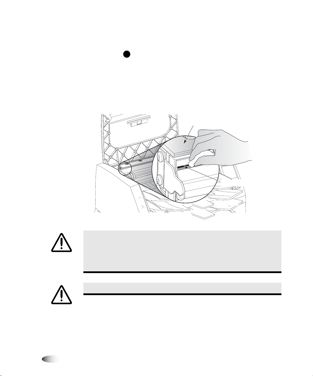
5. From the
menu option.
Open Top Cover
menu, select the
Move Ribbon Carriage
6. Press the key to move the ribbon carriage down and out of
T
the way.
7. Locate the print bead and nosepiece, shown in the following
figure.
Carefully wipe along
print bead until clean
Nosepiece
Print bead
CAUTION
• Use only the print head cleaning wipe when cleaning.
• Do not touch the glass surface of the thermal print head with fingers;
wearing gloves is advised.
WARNING The thermal print head may be hot.
7-4 Preventive Maintenance
To avoid thermal print head damage:
Page 86

8. Using the print head cleaning wipe provided with the imager’s
cleaning kit, carefully wipe back and forth along the entire
length of the print bead line with moderate pressure. The
cleaning wipe may become discolored. Repeat the back and
forth motion until the print bead is completely clean.
9. Clean any dust or other contaminants from the nosepiece.
10. Looking in from the side of the imager, locate the orange or
white platen roller and donor guide bar, shown in the following
figure.
Preventive Maintenance
11. If the
Move Ribbon Carriage
to return to the
12. From the
option.
Donor
guide bar
Open Top Cover
Open Top Cover
Platen Roller
(orange or white)
menu is displayed, press the key
W
menu.
menu, select the
Rotate Platen
menu
The
Rotate Platen
menu is displayed.
13. Using the platen roller cleaning wipe provided with the imager’s
cleaning kit, rub the wipe in one direction only along the entire
length of the platen roller from end to end until all visible
contaminants are gone. Do not rub back and forth.
Horizon Start Manual 7-5
Page 87

Press the or key to incrementally rotate the platen roller
S
T
so that you can clean its entire surface.
CAUTION
Damage to the platen roller may occur if the
Use only the platen roller cleaning wipe when cleaning the platen roller.
print head cleaning wipe
is used.
14. Clean any dust or other contaminants from the donor guide bar
using the platen roller or print head cleaning wipe provided
with the imager’s cleaning kit.
15. Wait for the thermal print head and platen roller to dry
thoroughly.
CAUTION
the imager. Allowing the head to heat up again while still wet will cause damage.
The thermal print head must be completely dry before attempting to use
If you need to reload the color ribbon, go to step 16. Otherwise
go to step 18.
16. From the
menu option. Press the key to move the ribbon carriage up
Open Top Cover
menu, select the
S
Move Ribbon Carriage
so you can reload the color ribbon.
17. Reload the color ribbon, as shown in the following figure.
Spring-loaded
18. Close the top cover.
7-6 Preventive Maintenance
spindles
Black (Supply)
Gray (Take-up)
Page 88

Cleaning the Pick Tires
Some Horizon users may prefer to use the Horizon Cleaning
Cassette to clean the pick tires, rather than using the platen roler
cleaning wipe. The Horizon Cleaning Cassette, part number SP00279, can be ordered by contacting your Codonics
representative.
Preventive Maintenance
1. Press the imager’s key, and wait until the imager enters the
PAUSE
Paused state.
2. Remove the receive trays, as shown in the following figure.
Receive trays
10"
x
8"
e
iz
S
A
7"
1
x
14"
WARNING With the receive trays removed, touch only those internal
components that are colored green (except for the pick tires, refer to the figure
on page xx). Remove rings, ties, jewelry, and other items, and tie back hair, so
that they do not fall into or get caught in the imager.
Horizon Start Manual 7-7
Page 89
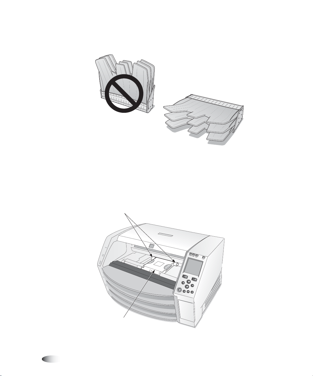
3. Place the receive trays on a flat surface, as shown in the
following figure.
Correct
Incorrect
4. Remove any cassettes from the supply slots.
5. Locate the pick tires.
There are three pickers, one for each supply slot. The topmost
picker is shown in the following figure.
Pick tires
7-8 Preventive Maintenance
Picker
Page 90

6. Using the platen roller cleaning wipe provided with the imager’s
cleaning kit, wipe around each pick tire with the cleaning wipe.
The cleaning wipe may become discolored.
Preventive Maintenance
CAUTION
to remove and could eventually damage the tires.
CAUTION
tires could be damaged if you use the print head cleaning wipe.
Do not touch the pick tires with fingers; body oils from your fingers are hard
Use only the platen roller cleaning wipe when cleaning the pick tires. The
7. Wait for the pick tires to dry thoroughly.
8. Replace the receive trays and any media cassettes that were
removed.
Horizon Start Manual 7-9
Page 91

Page 92

8
Film Calibration
Film calibration is the process of characterizing a given combination
of imager and
compensate for imager-to-imager variation and supply
cassette-to-cassette variation.
DirectVista
grayscale film to allow the imager to
Film Calibration
8
To perform a
film
calibration
3
When a
for the first time, the imager will print a test sheet and read that test
sheet with the built-in densitometer, then recalibrate based on the
results.
You can also perform a film calibration manually.
1. Press the key.
2. Select the following menu options:
3. Select the appropriate supply slot, then press the key.
NOTE:
loaded, the calibration will not run.
DirectVista
MENU
The Main Menu displays.
Utilities
Film Calibrate
The Film Calibration menu displays, allowing you to choose the
supply slot (referred to as Cassette 1, 2, or 3) in which the
DirectVista
The imager prints a test sheet, recalibrating that cassette based
on the result.
If the selected supply slot does not have a
grayscale film cassette is loaded into the imager
grayscale film cassette is loaded.
ENTER
DirectVista
grayscale film cassette
Horizon Starter Manual 8-1
Page 93

Page 94

9
Troubleshooting
Sources of Status Information
Control Panel
The control panel has
when the imager needs attention.
ALERT
and
FAULT
indicators, which light
Error Log
The imager logs error messages to a file.
1. Press the key.
The Main Menu displays.
2. Select the following menu options:
Utilities
MENU
Error Log
Online Help for Displayed Messages
You can display help text for a message displayed in the Status
window by moving the selector arrow to the message, then pressing
HELP
the key.
Troubleshooting
Horizon Starter Manual 9-1
Page 95

Troubleshooting Tables
Table 9-1. Startup and Print Job Troubleshooting
Problem Possible Causes Solutions
Imager does not power up
when pressing the
(power) key at the control
panel.
Control panel display
shows an error during
startup.
Imager does not respond
to pressing any control
panel keys.
Imager is not turned on.
Power cord is not properly connected.
No power at the outlet.
Internal fuse or power supply is bad.
Hardware component failed to initialize,
component failure.
Imager software has crashed.
Push the power rocker switch at the
back of the imager to the 1 (on) position,
then retry pressing the key at the
control panel (refer to “Powering On the
Imager—First Time” on page 1-8).
Reset power cord on back of imager.
Try plugging another device into the
outlet to check whether there is any
power. If there isn’t power to the outlet,
then check to see why.
The internal power supply contains an
integrated fuse which is not user
serviceable. Contact technical support.
Cycle power by pushing the rocker
switch at the back of the imager to the 0
(off) position. Wait 10 seconds. Refer to
“Powering On the Imager—First Time”
on page 1-8. If this does not clear the
condition, contact technical support,
making a note of the error message.
Press and hold down the key at the
control panel to force a shutdown. Wait
for the imager to power down, then
press the key again to restart.
9-2 Troubleshooting
If this does not clear the condition, then
cycle power. Refer to “Powering On the
Imager—First Time” on page 1-8).
If this still does not clear the condition,
contact Codonics technical support.
Page 96

Table 9-1. Startup and Print Job Troubleshooting (cont.)
Problem Possible Causes Solutions
Print jobs have been sent
but the A
CTIVE light never
flashes.
Images transfer but no
sheet is printed.
Internal problem with imager or with
network connection.
Trying to use an unsupported feature
(for example, unsupported media, or
the source—DICOM or PostScript—is
not supported on your imager).
A temporary feature key has expired.
Correct media not loaded.
A temporary feature key has expired.
Check that network cable is properly
connected.
Check that the Horizon imager’s
network settings are correct.
Check that the Horizon imager’s IP
address is set correctly at the host
sending the print job.
Check that you are using only features
that were purchased for and enabled on
the imager.
Check the error log using the Error Log
function to see whether a required
feature is not enabled. Contact your
Codonics representative to purchase a
permanent corresponding feature key.
Look for message at the control panel
status window, and load that requested
media type.
Check the error log using the Error Log
function to see whether a required
feature is not enabled. Contact your
Codonics representative to purchase a
corresponding permanent feature key.
Troubleshooting
Image transfers but the
image’s cell on the printed
sheet is empty. Instead,
the cell contains the
message “image
processing failed.”
Trying to use an unsupported feature.
Check that you are using only features
that were purchased for and enabled on
the imager.
Unknown or corrupt image file format. Make sure images being sent to the
imager are one of the supported
formats.
Make sure the sending application is
not sending corrupt or incomplete
images.
Reinstall imager software.
Horizon Starter Manual 9-3
Page 97

Table 9-1. Startup and Print Job Troubleshooting (cont.)
Problem Possible Causes Solutions
Sheet and/or image
settings on printed sheets
do not reflect what is set
through the control panel.
Status screen indicates
“Head cooling, please
wait ...” for extended
period of time (greater
than one minute), or this
message displays often.
Settings entered through the DICOM
application interface a Job Setting are
overriding the imager’s Default User
Settings.
Improper ventilation. Allow at least 10 cm (4 in.) at back and
To use the Default User Settings
specified at the control panel, select a
Horizon imager Called AE Title that
does not specify any Job Settings
parameters (for example, Print_SCP).
Also, do not specify any custom
settings through the DICOM application
interface or PostScript printer settings.
All settings will then defer to the
imager’s Default User Settings.
sides of imager.
Move imager to a cooler location.
Table 9-2. Sheet Jam Troubleshooting
Problem Possible Causes Solutions
Sheet jams or misfeeds. The imager is being operated in an area
of high or low humidity that is outside of
the specified range for the imager. This
can cause the media to curl.
Check the media for curling or other
distortion. If there is distortion, replace
the media. Try to control temperature
and humidity in the area where the
imager is located, or move the imager to
a more suitable location.
9-4 Troubleshooting
Sheet is still jammed in the imager.
Dirty pick tires or platen roller.
Sheets in the cassettes are blocked or
stuck together due to heat, humidity, or
improper storage.
Receive tray is full.
If a sheet is still jammed in the imager,
remove it (refer to “Clearing a Sheet
Jam” on page 9-9).
Clean the platen roller (refer to
“Cleaning the Thermal Print Head
and Platen Roller” on page 7-3) and the
pick tires (refer to “Cleaning the Pick
Tires” on page 7-7).
To help prevent sheets from sticking
together, store cassettes upright (the
way they come packed in their shipping
boxes), not lying flat.
Remove sheets from the receive tray.
Page 98

Table 9-3. Image Quality Troubleshooting
Problem Possible Causes Solutions
Scratches (physical
abrasions) on the sheet.
Spots or irregular streaks
on the sheet.
Clear, hard-edged
vertical white streak on all
sheets.
Vertical streaking across
the entire sheet.
Dark spot that repeats
every few inches on the
sheet.
Multi-colored jagged
streaks on colored sheet.
There is dirt on the thermal print head,
or a burr or abrasion on a component in
the media path.
Dust on the sheet. Clean the thermal print head and platen
Blown element on the thermal print
head or bad cable.
Thermal print head needs to be
calibrated.
Dust on the platen roller. Clean the platen roller (refer to
The ribbon may be wrinkled on the
spool, or the ribbon is damaged.
Clean the thermal print head (refer to
“Cleaning the Thermal Print Head
and Platen Roller” on page 7-3).
Perform general cleaning procedures
(refer to the
roller (refer to “Cleaning the Thermal
Print Head and Platen Roller” on
page 7-3).
Perform general cleaning procedures
(refer to the
Need new thermal print head or cable.
Contact technical support.
Calibrate the thermal print head (refer
to the
“Cleaning the Thermal Print Head
and Platen Roller” on page 7-3).
Install a new ribbon [refer to “Changing
the Ribbon (ChromaVista)” on
page 3-7] and make another print.
Horizon User’s Manual
Horizon User’s Manual
Horizon Technical Manual
).
).
).
Troubleshooting
Table 9-4. Media Cassette and Ribbon Troubleshooting
Problem Possible Causes Solutions
Printed sheets are falling
from the imager.
Receive tray is full.
Imager is angled forward.
Remove the sheets from the receive
tray.
Slightly raise height of surface below
front feet of imager.
Horizon Starter Manual 9-5
Page 99

Table 9-4. Media Cassette and Ribbon Troubleshooting (cont.)
Problem Possible Causes Solutions
The imager cannot read
the cassette barcode.
The imager indicates that
the barcode is invalid.
The imager indicates that
the media is
contaminated or that the
sheet count has been
exceeded.
The imager indicates that
media needs to be
loaded.
Imager does not
recognize that cassette is
present.
If the cassette is valid, the barcode label
may not be correctly positioned or the
barcode reader window may be dirty.
There is a problem with the cassette’s
barcode.
Additional sheets were inserted into the
supply cassette beyond what was
originally packaged.
The printer has been jamming.
A print job was received that requires a
media type/size that is not currently
loaded.
The cassette is loaded but not seated
properly.
If the imager does not respond to
having the cassette inserted in any of
the slots, the software may not be
operating properly.
Check the barcode label position and/or
clean the barcode reader window. If this
does not work, manually enter the
barcode number (refer to the
User’s Manual
Contact your Codonics representative.
For quality control reasons, you cannot
add sheets to a supply cassette.
Perform general cleaning procedures
(refer to the
Load the appropriate cassette or purge
the print queue to remove that job (refer
to “Purging Print Jobs” on page 9-19).
Reseat the cassette.
Reboot the imager.
).
Horizon User’s Manual
Horizon
).
The imager indicates that
a media supply cassette
is not supported.
The imager indicates that
the receive trays must be
inserted.
The control panel
indicates that no ribbon is
loaded, when a ribbon is
loaded.
9-6 Troubleshooting
Cassette sensors are dirty.
If only one slot is not working, that slot’s
cassette sensor may have failed.
The imager does not support that media
type/size option.
The receive trays are not installed, or
are not seated properly.
The ribbon currently loaded is not a
Codonics ribbon.
Failed ribbon sensor.
Clean the cassette sensors. Contact
technical support for details.
Move the cassette to a different slot.
Then contact technical support.
Contact your Codonics representative
to purchase that media option.
Properly install the receive trays.
You must use Codonics ribbon.
Contact technical support.
Page 100

Table 9-4. Media Cassette and Ribbon Troubleshooting (cont.)
Problem Possible Causes Solutions
Film calibration failed. Film too light or too dark.
The film is facing the wrong way.
A jam prevented the film from moving.
There is a problem with the imager. For
example, two films were picked at once,
or the imager is outside its operating
temperature.
Table 9-5. Miscellaneous Troubleshooting
Try using another cassette, or move the
cassette to another slot.
Flip the top sheet of media upside down
and repeat calibration. If callibration is
successful, call technical support if you
believe that all sheets in the cassette
have been loaded upside down. For
quality control reasons, media should
never be reloaded into a cassette.
Check for and correct any sheet jams.
Wearing rubber gloves, carefully fan the
media. To help prevent sheets from
sticking together, store cassettes
upright (the way they come packed in
their shipping boxes), not lying flat.
Make sure that the imager fan is
working, and that the room is within the
proper temperature and humidity
operating ranges (refer to Appendix A
for operating specifications).
Troubleshooting
Problem Possible Causes Solutions
Control panel displays
“Invalid smart card.”
Experiencing connection
errors at console or
workstation from which
DICOM print jobs are
sent.
Smart Card is not firmly seated.
Incorrect Smart Card is inserted from
another model imager.
Smart Card is damaged.
Running DICOM Lite on imager, and
need more connections than is
provided by DICOM Lite.
Remove and insert the Smart Card.
Reinsert the imager’s original Smart
Card.
Contact technical support for a
replacement.
Contact technical support about
upgrading to full DICOM.
Horizon Starter Manual 9-7
 Loading...