

Page 1
Title: CMC III Bipolar Date: 3-24-2014
By: Codman/Depuy/J&J
File =Codman CMC ESU .doc
DISCLAIMER: THIS PROCEDURE PROVIDED "AS IS" AND WITH
POSSIBLE FAULTS. USER MUST VERIFY BEFORE USE. NEITHER
PROVIDER NOR WEBSITE ASSUMES ANY RESPONSIBILITY FOR ITS USE.
1. General
Applies to “System CMC III” Electrosurgical Generator
P/N 80-1172
Specifications: See Service Manual
2. Reference Documents
• User Instructions (no P/N available).
• Service Manual (no P/N available)
• http://www.depuy.com/healthcare-professionals/product-
details/malistrade-cmc-iii-bipolar-cut-and-coagulationsystem
3. Tools / Fixtures / Accessories
Electrosurgical Analyzer: See note below.
Pair of banana-plug interconnect leads
Safety Tester
Irrigation Module P/N 80-9100 shown 80-1164 (optional)
Adapter Cable (Main unit to irrigator)
Footswitch, ex: 80-1149
4. Performance Verifications
4.1. Initial Inspection
Check unit for any damage; i.e. connectors, power cord,
the footswitch and its cable. Also, the main unit/irrigator
cable may require repair despite a good appearance.
4.2. With no accessories plugged in, turn on unit. Verify that
both displays soon default to 35, along with computer
voice identifying same.
4.3. Setup
Connect analyzer to ESU using a banana plug test leads.
Before activating the unit, check that the up and down
switch-buttons can change each display up and down.
Note: Service manual power output data assumes an analyzer with 50 and
400 ohm settings. As an alternate, the analyzer shown has load settings of
500 and 125 ohms. Refer to load curves in Appendix for further reference.
Power vs Dial Setting relationships in the service manual, and all charts
below, are listed as “typical”.
4.4. Cut Mode
Set the analyzer to 125 ohm load. When pressing the cut pedal, output wattage will be proportional
to, but not match, the power setting, peaking at 150 watts. Refer to charts in the appendix for
acceptable results, which depend on load.
4.5. Coag Mode
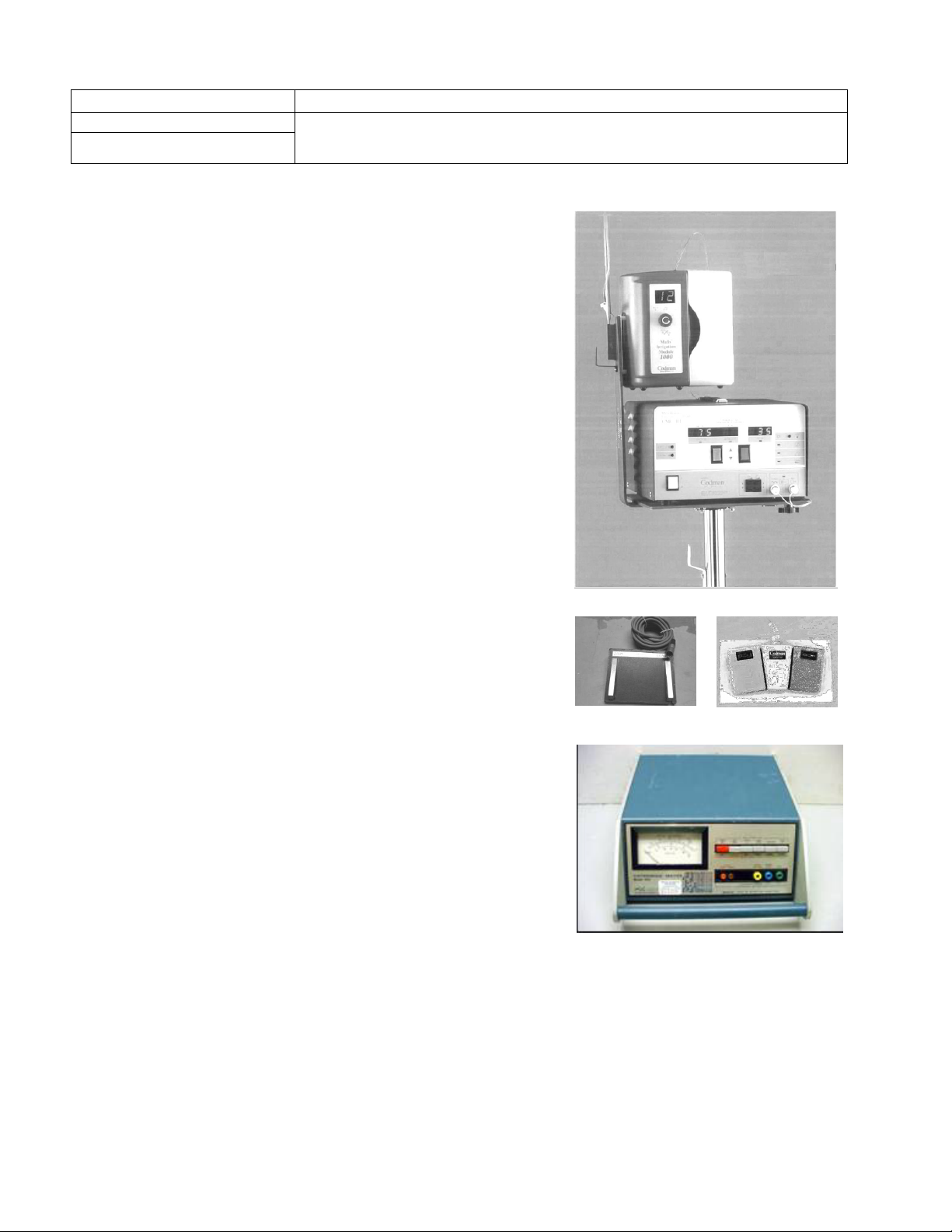
ESU UNIT with IRRIGATOR
Two Footswitch Styles
DEMPSEY 443 ANALYZER
Page 2
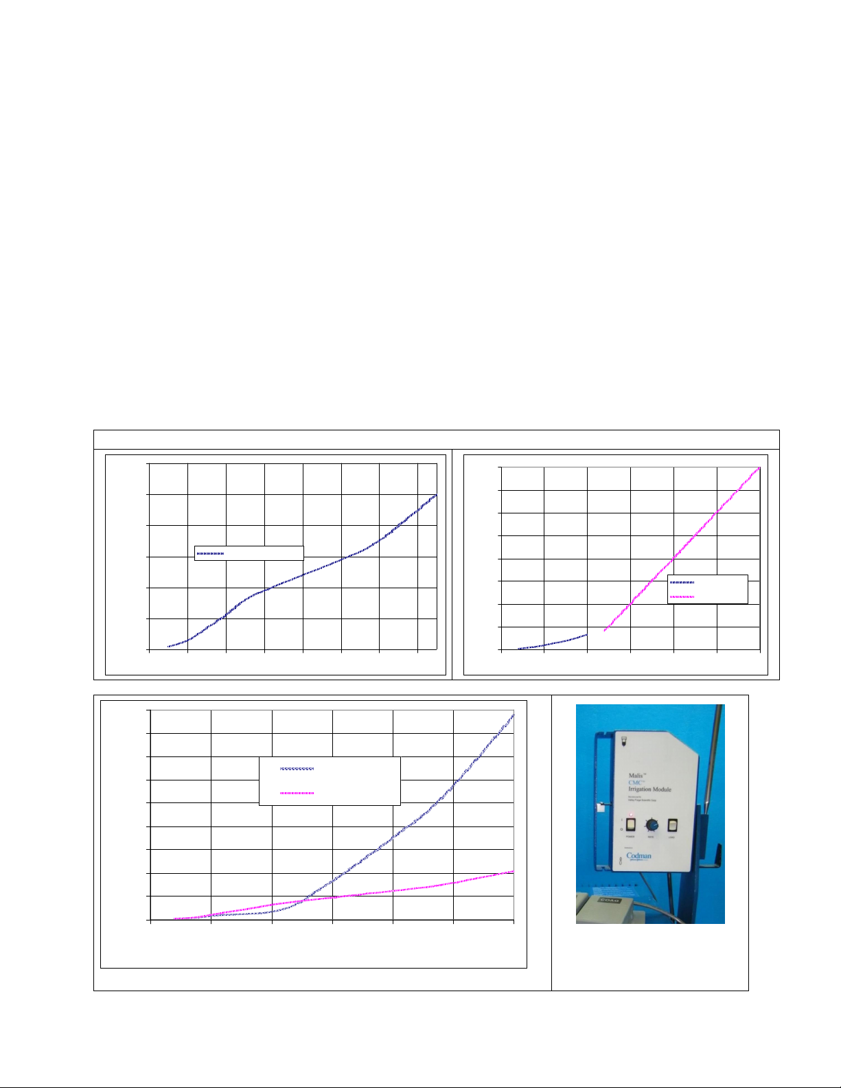
Set analyzer load to 125 ohms and “high sense”. When pressing the coag pedal, output wattage
will be proportional to, but not match, the power setting, peaking at 40-50 watts. Refer to charts in
the appendix for typical results, which depend on load.
4.6. Re-Calibration (only if necessary)
Any single, or all, of the CMC-III's 40 power output settings may be calibrated individually by
changing the target DAC calibration value (as stored in memory) associated with each setting.
DAC value adjustments may be performed with the CMC-III in the calibration mode. See Service
Manual. This requires an ESU analyzer capable of 50 and 400 ohms.
4.7. Irrigator
When the main unit is keyed, the rollers of the irrigator will turn for several seconds, and then stop.
4.8. Other Safety Checks
Using the safety tester, check that line leakage with ground open is less than 50 uA.
Using the safety tester, check that ground lead resistance is less than 0.15 ohms.
Resistance between case and either bipolar output contact: >10 megohms.
APPENDIX
60
TYPICAL
50
40
Wat ts
30
20
10
0
0 20 40 60 80 100 120 140
180
160
140
120
100
COAG OUTPUT vs Display
Coag into 50 ohms
Power Setting
TYPICAL OUTPUT INTO 125 OHMS
POWER OUTPUT RELATIONSHIPS
200
175
TYPICAL CUT OUTPUT vs Display
150
125
100
W at t s
75
50
25
0
0 25 50 75 100 125 150
CUT OUTPUT
COAG OUTPUT
'@ 50 Ohms
'@ 400 Ohms
Power Setting
80
Watts
60
40
20
0
0 25 50 75 100 125 150
DISPLAY SETTING
Older version – Irrigation
Module
 Loading...