

Page 1
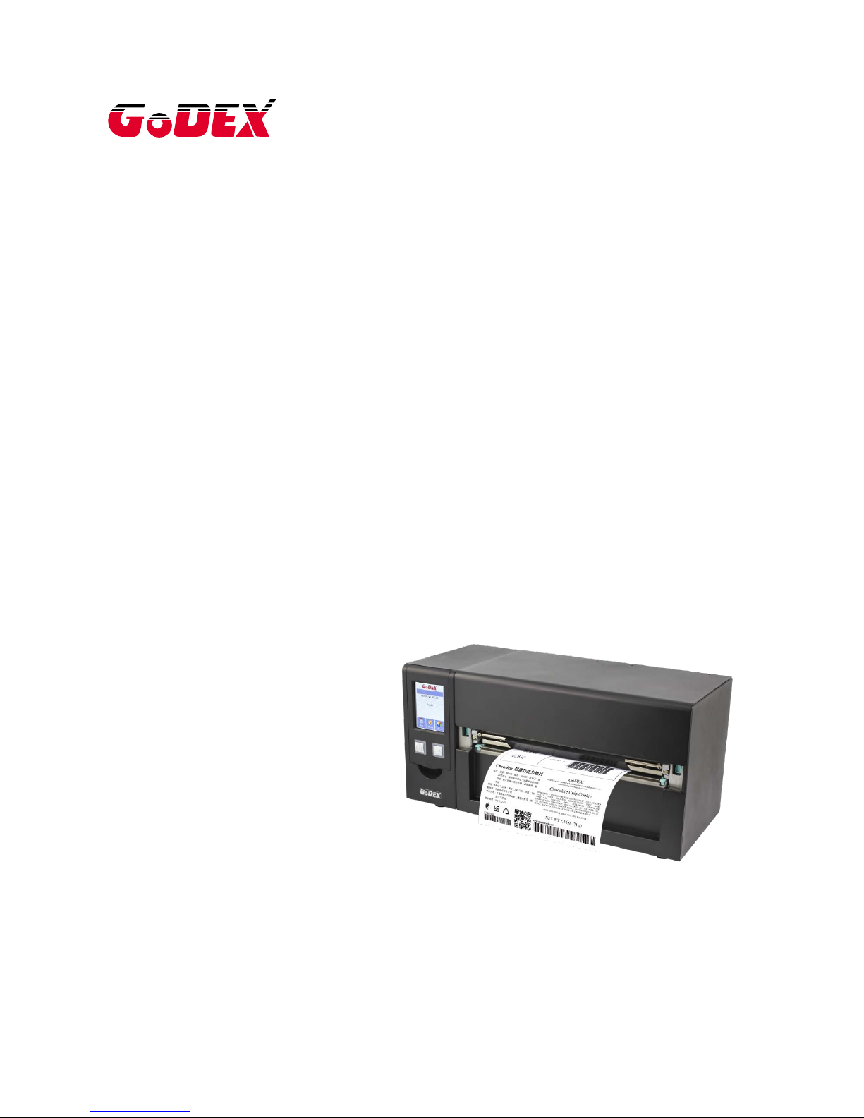
HD830i BARCODE PRINTER
USER MANUAL
: HD830i
: Rev.A
: 2017.03
: 920-016611-00
User Manual
Version
Issue Date
P/N
Page 2

1 Barcode Printer 1
1-1 Package Contains ........................................................................................................................................ 1
1-2 Barcode Printer Introduction ....................................................................................................................... 2
2 Barcode PrinterInstallation .................................................................................................................................. 4
2-1 Media Installation.......................................................................................................................................... 4
2-2Printing Mechanism Opening ...................................................................................................................... 5
2-3Ribbon Installation.......................................................................................................................................... 6
(4 inch Ribbon ) .................................................................................................................................................... 6
(8 inch Ribbon ) .................................................................................................................................................... 7
2-4 Label Installation ........................................................................................................................................... 9
2-5 Connection with PC .................................................................................................................................... 12
2-4 Driver and Golabel Installation................................................................................................................. 13
2-10 Wizard CD Other Choice Installation .................................................................................................. 16
3 Barcode Printer Operation ................................................................................................................................ 19
3-1 Barcode Printer Operation Interface ....................................................................................................... 19
3-3 LAN Setting Operation Instruction ............................................................................................................ 25
Main Manu .......................................................................................................................................................... 25
3-5 Error Message .............................................................................................................................................. 32
4 Installing the NetSetting software ................................................................................................................ 37
4-2 The Interface of NetSetting ..................................................................................................................... 39
5 Barcode Printer Options .................................................................................................................................... 46
5-1 Pre -step for Options Installation .............................................................................................................. 46
5-2 Cutter Installation ........................................................................................................................................ 47
6 Maintenance and Adjustment......................................................................................................................... 51
6-1 Print Head Replacement............................................................................................................................ 52
6-2 Print Line Adjustment .................................................................................................................................. 53
6-4 Print Head Cleaning.................................................................................................................................... 55
6-5 Print Head Pressure Adjustment ............................................................................................................... 55
6-6 Ribbon Wrinkle Adjustment ....................................................................................................................... 57
6-7 Cutter Error Trouble Shooting .................................................................................................................... 57
6-8 Trouble Shooting .......................................................................................................................................... 59
Appendix - Printer Specification ..................................................................................................................... 60
Appendix - Communication Port Specification ........................................................................................... 61
Appendix – Wi-Fi Setting…………………………………………………………………………………………….59
Appendix – Bluetooth Setting…..………………………………………………………………………………….66
Appendix – FILE MANIPU LAT ION WHEN USING USB STICK…………………………………………………….78
Page 3
Page 4

FCC COMPLIANCE STATEMENT
FOR AMERICAN USERS
Federal Communication Commission Inte rference Statement
This equipment has been tested and found to comply with the limits for a C lass B digital device, pursuant to
Part 15 of the FCC Ru les. These limits are designed to provide reaso nable protection against harmful
interference in a residential installation. This equipment generates, uses and can radiate radio frequency
energy and, if not installed and used in accordance with the instructions, may cause harmful interference
to radio communications. However, there is no guarantee that interference will not occur in a particular
installation. If this equipment does cause harmful interference to radio or television reception, which can be
determined by turning the equipment off a nd on, the user is encour a ged to try to correct the interference
by one of the following measures:
● Reorient or relocate the receiving antenna.
● Increase the separation between the equipment and receiver.
● Connect the equipment into an outlet on a circuit different from that to which the receiver is connected.
● Consult the dealer or an experienced radio/TV technician for help.
This device compli es with Part 15 of the FCC Rules. Operation is subject to the following two conditions:
(1) This device may not cause harmful interference, and (2) this device must accept any interference received,
including interference that may cause undesired operation.
FCC Caution: Any changes or modifications not expressly approved by the party
responsible for compliance could void the user’s authority to operate this equipment.
TO WHICH THIS DECLARATION RELATES
IS IN CONFORMITY WITH THE FO LLOWING STANDARDS
FCC CFR Title 47 Part 15 Subpart B:2015 Class B,CISPR 22:2008 ANSI C63.4: 2014 ICES-003 Issue 6:2016, Class B
IEC 60950-1:2005(Second Edition)+Am1:2009+Am2:2013
EN55024:2010+A1:2015
EN55032:2012+AC:2013,Class B
EN61000-3-2:2014
EN61000-3-3:2013
AS/NZS CISPR 22:2009+A1:2010
Page 5

SAFETY INSTRUCTIONS Please read the following instructions carefully.
Keep the equipment away from humidity.
Before you connect the equi p ment to the power outlet, please check t h e
voltage of the power source.
Make sure the printer is off before plugging the power connector into
the power jack.
It is recommended that you connect the printer to a surge protector to
prevent possible transient overvoltage damage.
Be careful not to get liquid on the equipment to avoid electrical shock.
For safety and warranty reasons, ONLY qualified service personnel
should open the equipment.
Do not repair or adjust energized equipment under any circumstances.
CAUTION
Danger of explosion if battery is incorrectly replaced. Replace only with the equivalent
type recommended by the manufacturer.
Dispose of used batteries according to the manufacturer’s instructions.
Only use with designated power supply adapter model.
Changes or modifications not expressly approved by the party responsible for
compliance could void the user's authority to operate the equipment.
Specifications are subject to change without Note
Page 6
1
1 Barcode Printer
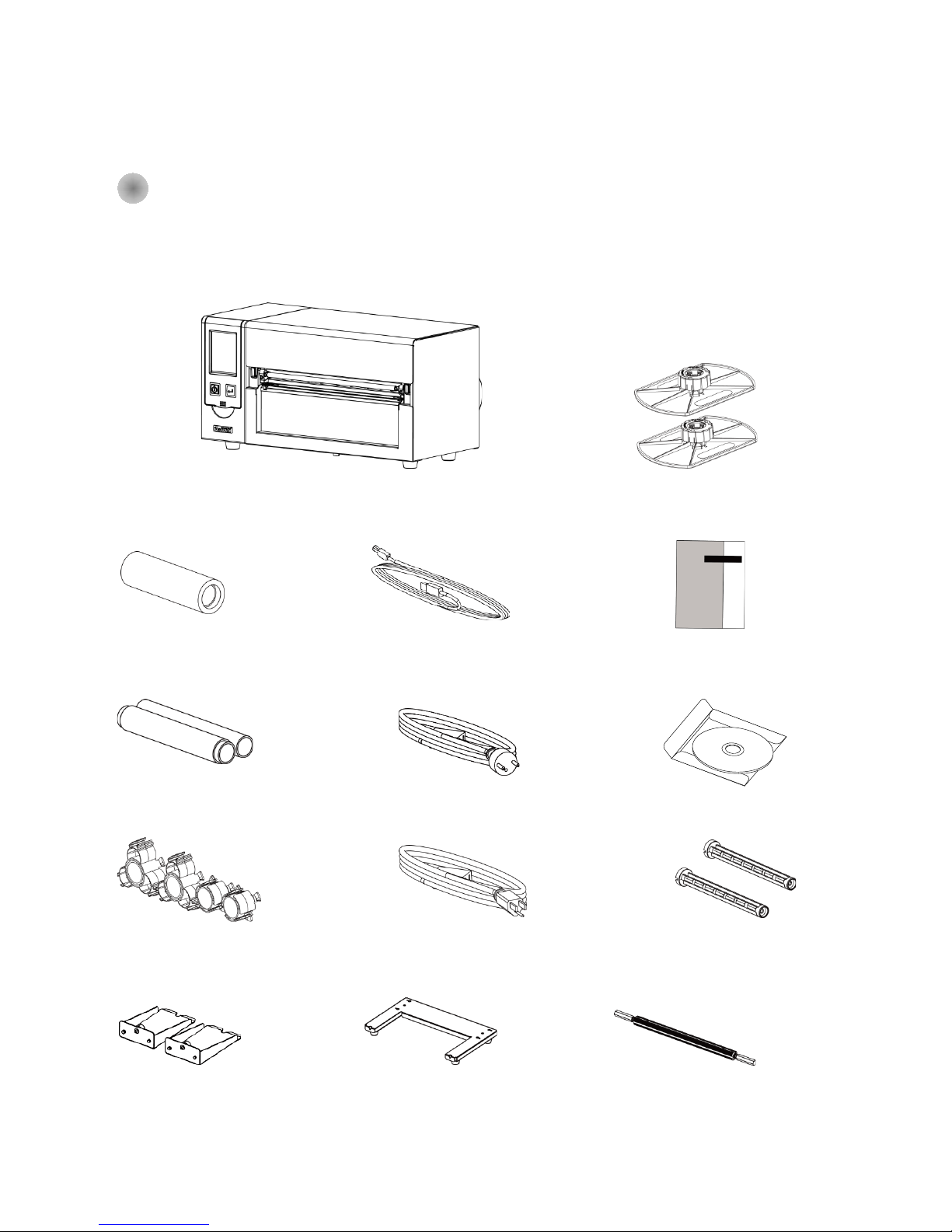
1-1 Package Contains
Please check that all of the following items are included with your printer.
(Package content and Logo style may vary per region。)
Barcode Printer
HD830i
Media Sample USB cable Quick Start Guide
Ribbon Power Cord CD
(EU)
1.5 inch/3 inch Adaptor
Ribbon Shaft
Label Roll Holder Media Holder Base Media Shaft
Power Cord
(US)
Label Roll Stopper
Page 7
2
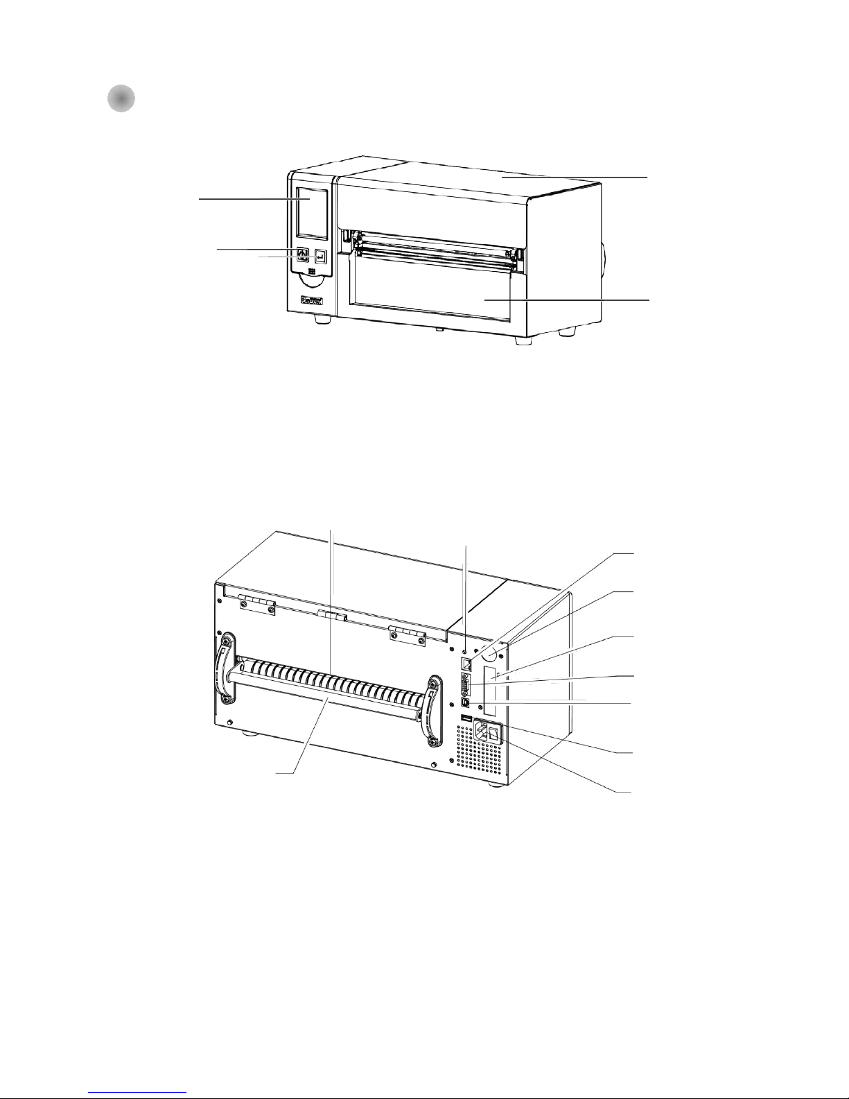
1-2 Barcode Printer Introduction
Front View
Rear View
(Interface might differed per Optional interface)
Paper Path
Calibration Key
USB 2.0
Power Plug
Power Switch
Top Cover
Front Panel
Touch Screen
Power Key
Feed Key
RS-232
BT/WiFi (Optional)
USB HOST
Parallel (Optional)
Ethernet
Media Damper
Page 8
3
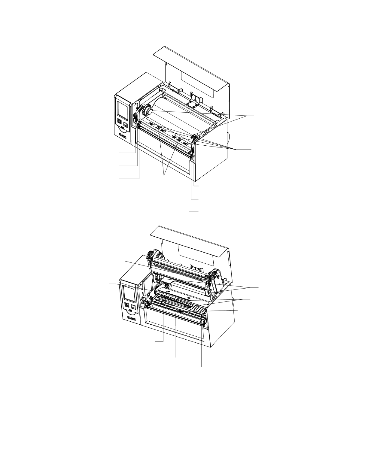
Open Top Cover
Ribbon Rewind
TPH Pressure Adjust knob
Movable Media Sensor
TPH Module
TPH Module
Hook
Print Frame Hook (Right)
Print Line Adjust Knob (Right)
Ribbon Tension Adjust Knob (Right)
Print Frame Hook (Left)
Print Line Adjust Knob. (Left)
Ribbon Tension Adjust Knob. (Left)
Movable See Through Sensor
Ribbon Supply
Platen
Roller
Label Width Adjust Holder
(Left)
Paper
Damper
Label Width Adjust Holder
(Right)
Page 9
4
2 Barcode PrinterInstallation
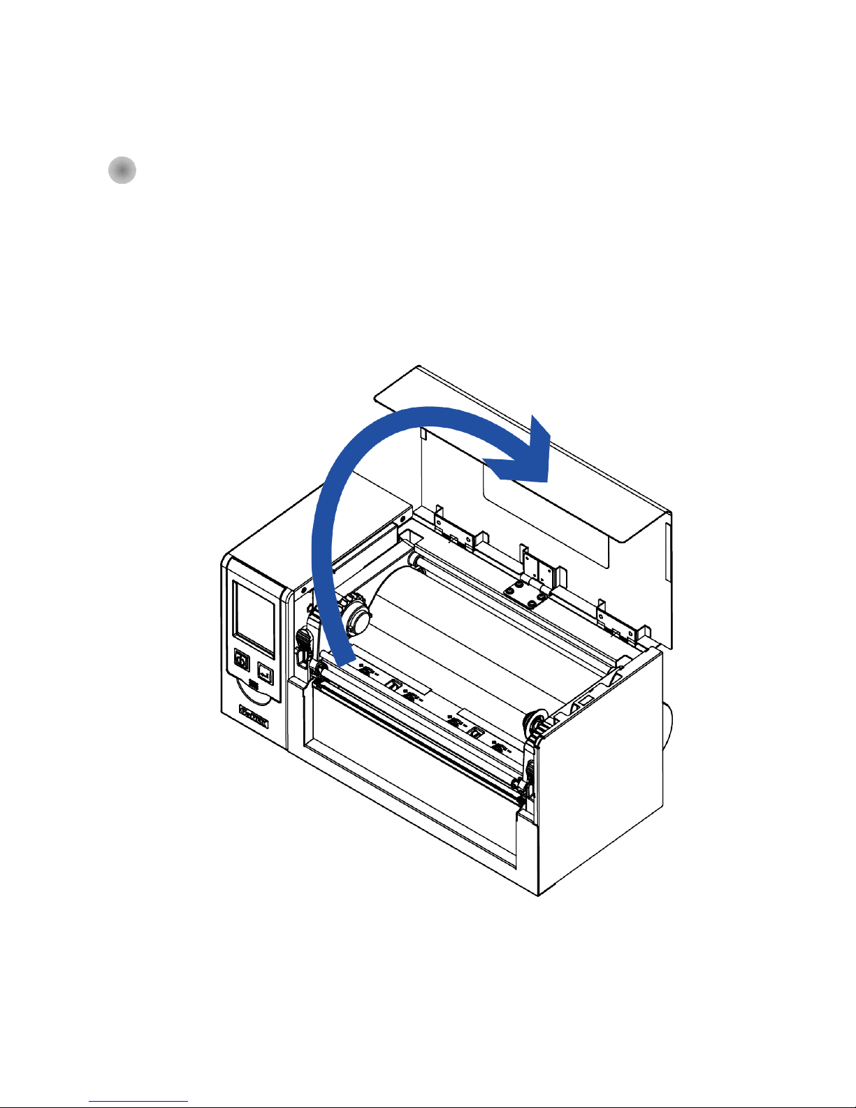
2-1 Media Installation
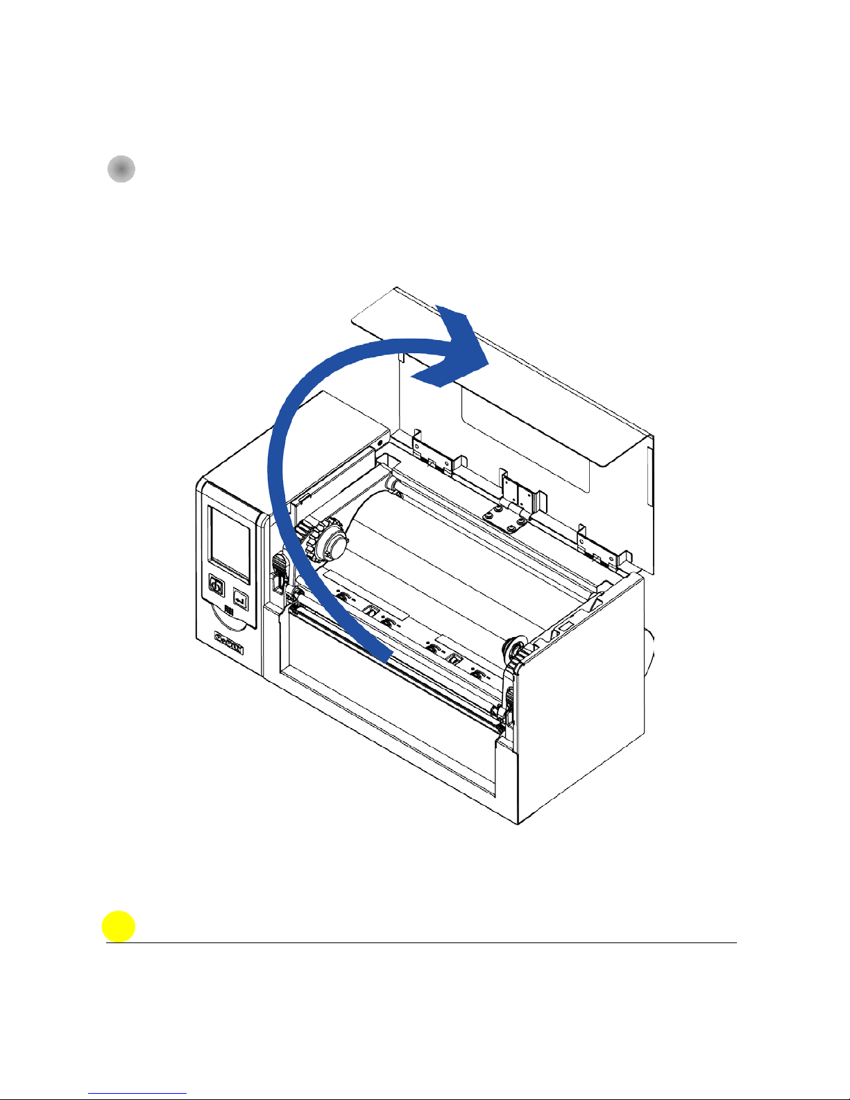
Lift up the top cover
Page 10
5
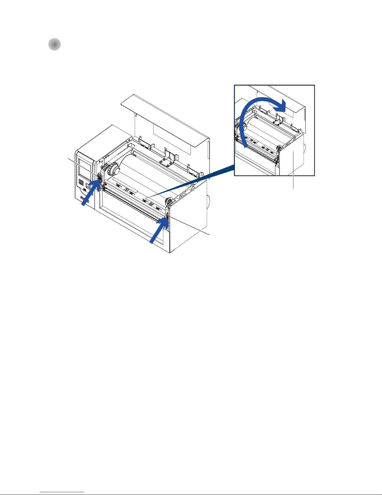
2-2 Printing Mechanism Opening
Push the Print frame hook on the side to head up the print frame.
Lift up the
print frame
Print Frame Hook
(Right)
Print Frame
Hook (Left)
Push
Push
Page 11
6
2-3 Ribbon Installation
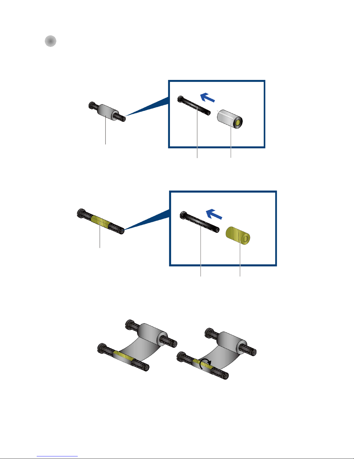
(4 inch Ribbon )
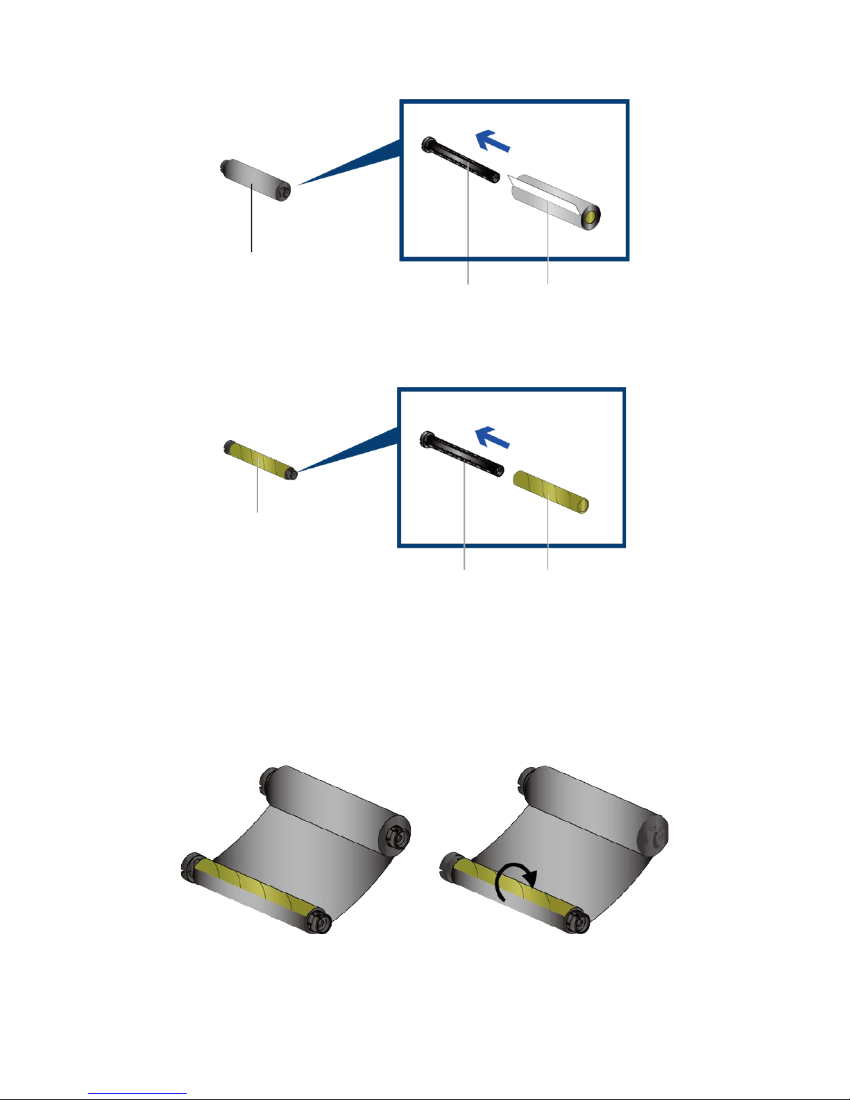
Plug a new ribbon roll into the ribbon Shaft
Install the empty ribbon core into ribbon shaft
Stick the ribbon with the Ribbon Rewind units and rolling 2~3 cycles.
New ribbon roll
Ribbon Shaft
Ribbon Supply
Ribbon Rewind
Ribbon shaft
Empty Ribbon Core
Follow the direction
Follow the direction
Rolling 2~3 cycles
Page 12
7
(8 inch Ribbon )
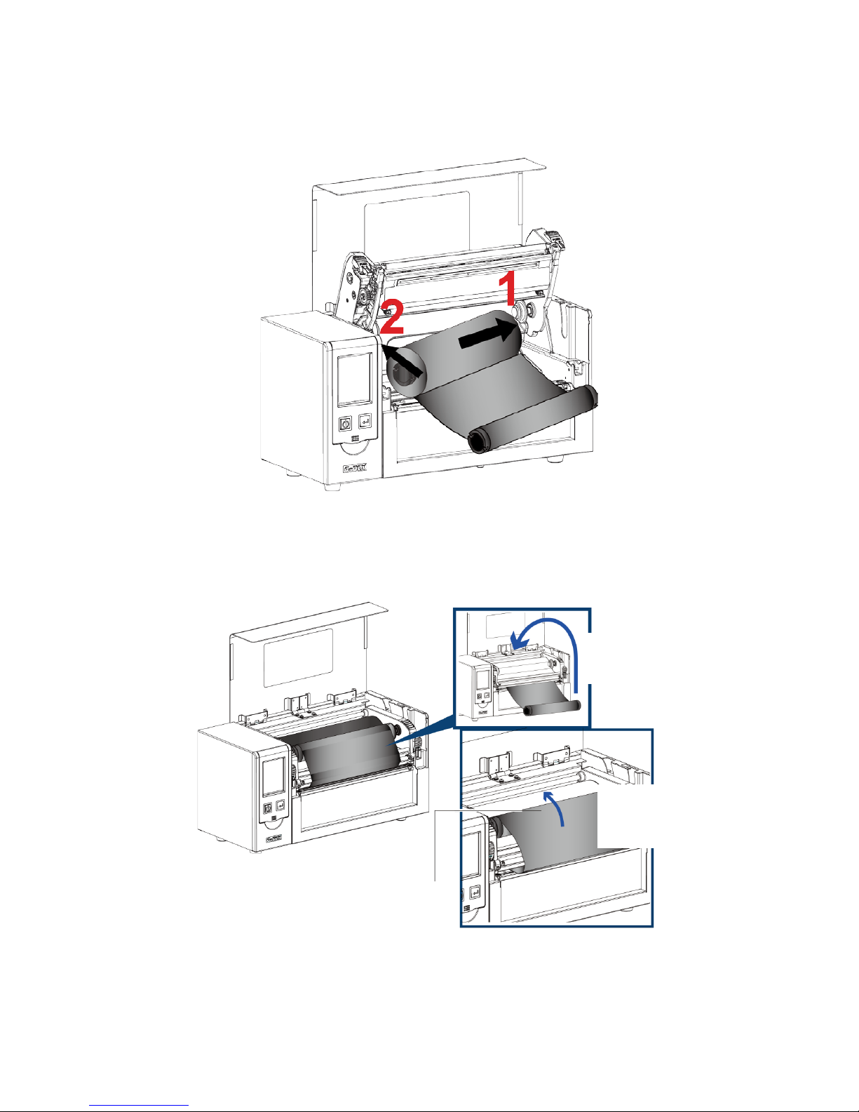
Install the empty ribbon core into ribbon shaft
Stick the ribbon with the Ribbon Rewind units and rolling 2~3 cycles
Ribbon Supply
Ribbon Rewind
Follow the direction
Follow the direction
Ribbon shaft New ribbon roll
Ribbon shaft
Empty Ribbon Core
Rolling 2~3 cycles
Page 13
8
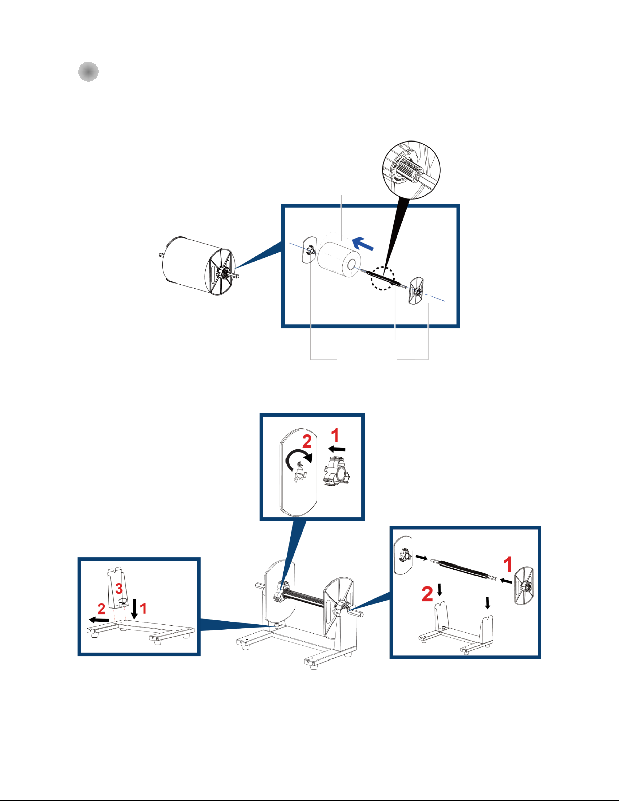
Install the Ribbon into the Barcode Printer
Follow the below drawing to install the ribbon in position.
Rolling to flat surface.
Put the Ribbon Rewind Assy into
position
Page 14
9
2-4 Label Installation
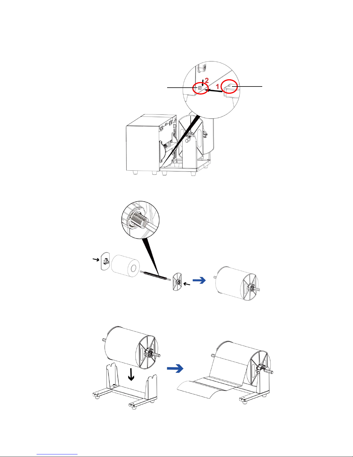
Label Roll Ass’y
Put the label roll into media spindle and then install the label roll s topper on the bo th side to make the
media roller in position.
Label Holder Stand
Follow the Arrow mark and No. to
assemble the s tand.
Label roll
stopper
Media Spindle
Label Roll
Follow the direction to secure the core adaptor
Follow the Arrow mark and No. to
assemble the s tand.
Page 15
10
Label Installation
Step 1. Following the arrow mark and No. to put the label roll holder into position.
Step 2. Following the below arrow mark and direction to put the label roll into position.
Step 3. Put the label roll into label roll stand.
Hook
Position Pin
Page 16
11
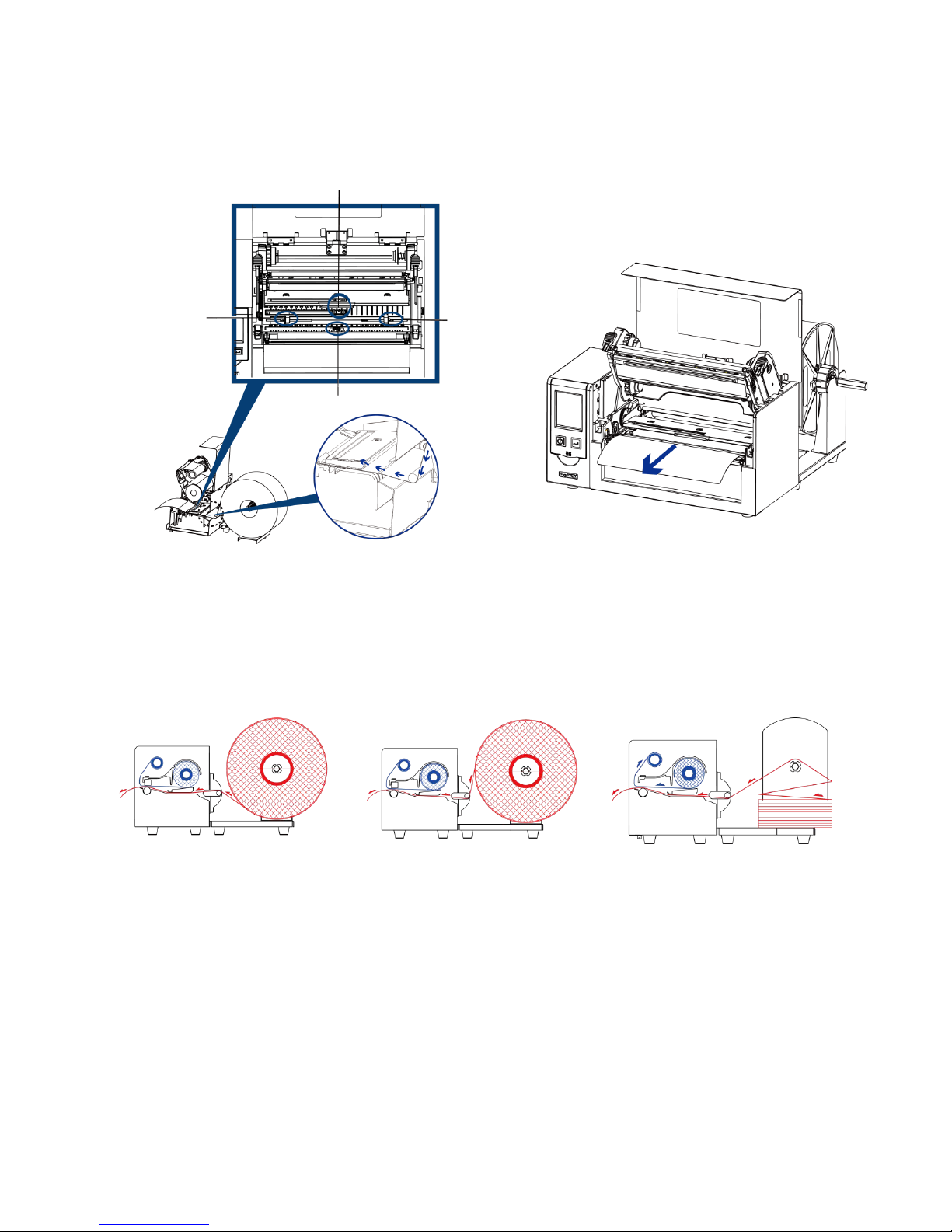
Step 4. Put the label pass through the label guide and then adjust the suitable label width
according to.
See Through Sensor
Reflective Sensor
Label Guide (Left)
Label Guide (Right)
Outside Label
Roll Installation
Fanfold paper
Installation
Inside Label Roll
Installation
Page 17
12
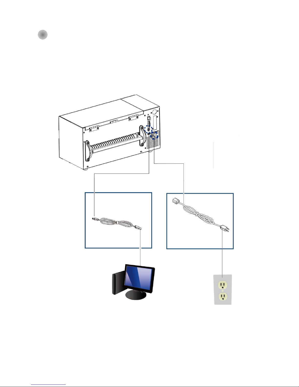
2-5 Connection with PC
1. Make sure the Barcode Printer power is in off status.
2. Put the power cord one side on the power plug, one side on the power adaptor.
3. Connect the transmission cable in between PC and printer (T he cable might be diffe red acco rding
to option selected) .
4. After the media (ribbon )installation, then power on the printer, wait the status turned to ready.
HD830i Barcode Printer
(The interface might be differ e d u pon
the options been selected)
B1
Power
cord
B2
Power cord
B2
Power Socket
A2
USB port
A1
USB port
B1
Power
A1
USB port
A2
USB port
Page 18
13
2-4 Driver and Golabel Installation
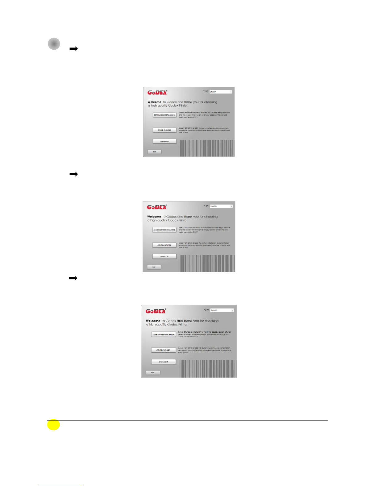
Step.01 Insert the Super Wizard CD in the CD/DVD drive of the host computer and the
installation program should pop up automatically. You will see the Welcome screen
first. On the Welcome screen, choose “STANDARD INSTALLATION”.
Step.02 The wizard will then ask you to make sure your USB and power cables are connected
and that the power is turned on. Then click “NEXT”.
Step.03 The next screen you will see is, “Install the GoLabel Software and Windows driver”. Click
“NEXT” to continue.
NOTE
* If the Super Wizard program did not run automatically, you can either turn on the “Auto-run” setting
for your CD/DVD driver or double-click the icon of CD/DVD driver to run the program manually.
Page 19
14
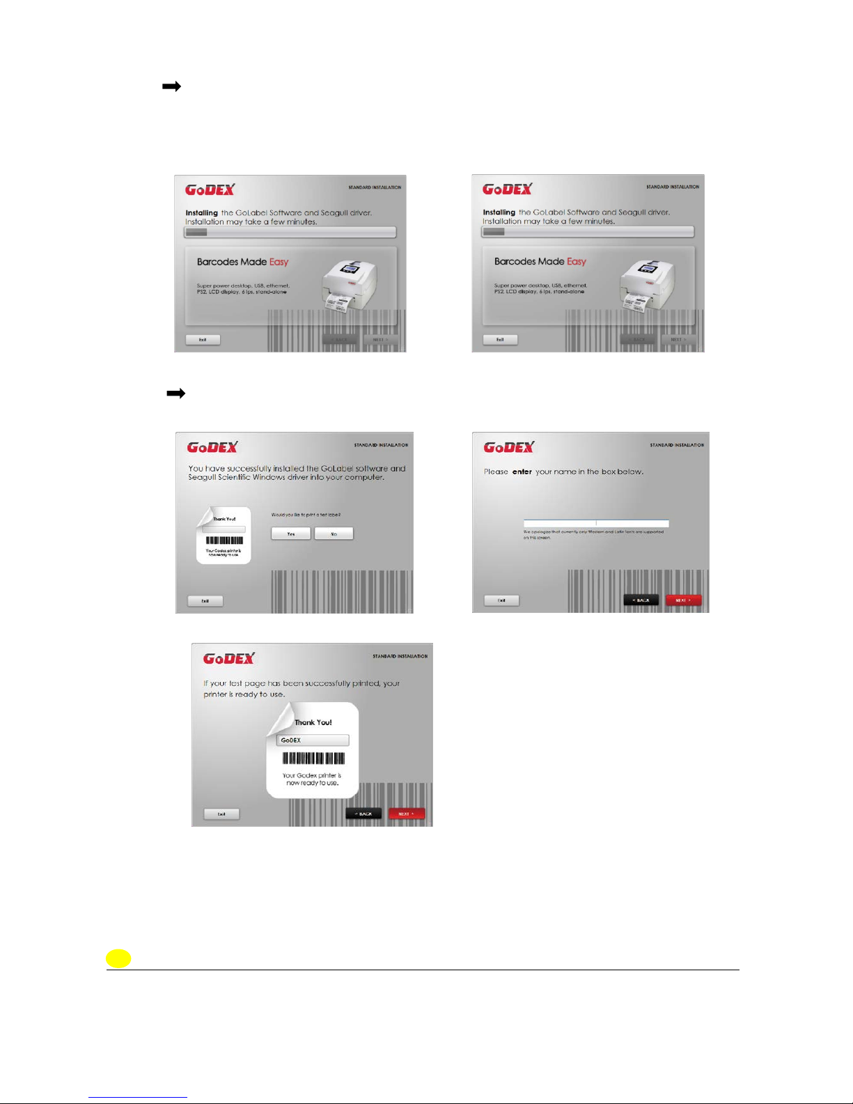
Step.04 As the printer driver and GoLabel are installing, a screen will display a progress bar.
While downloading completed you will see Installation completed. Click “NEXT” to
continue.
Step.05 You can also print a test label. If don’t print a test label, the screen display as step 6.
Note
* If you need more resources, tools or reference documents, you can also find them on Super Wizard
CD. Just click “Other Choices” on the Welcome Screen to access the files.
Page 20
15
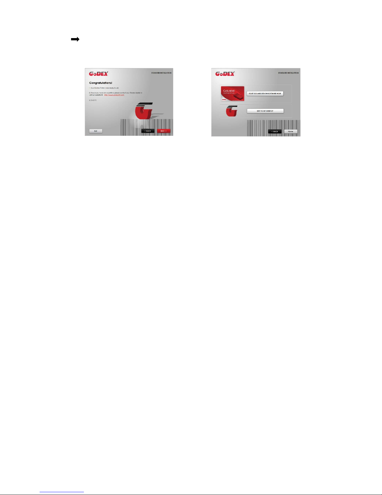
Step.06 Once the installation is complete, you can start to make and print labels with GoLabel
or through the printer driver.
Page 21
16
2-10 Wizard CD Other Choice Installation
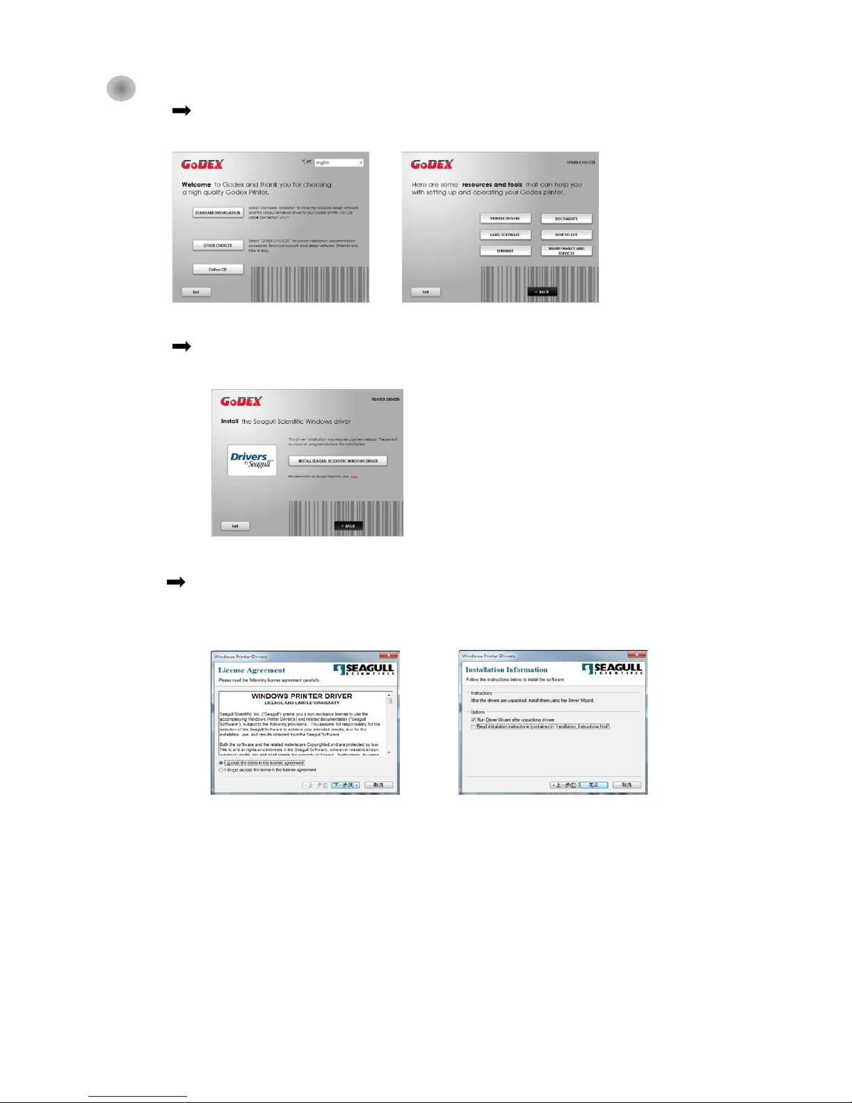
Step.01 Click “OTHER CHOICES” to next screen and select “PRINTER DRIVERS”.
Step.02 Click “INSTALL SEAGULL SCIENTIFIC WINDOWS DRIVER” to next screen, and click “NEXT”.
Step.03 Select “I accept the terms in the license agreement”, and click ”Next”,then
click ”Finish” to step 4.
Page 22
17
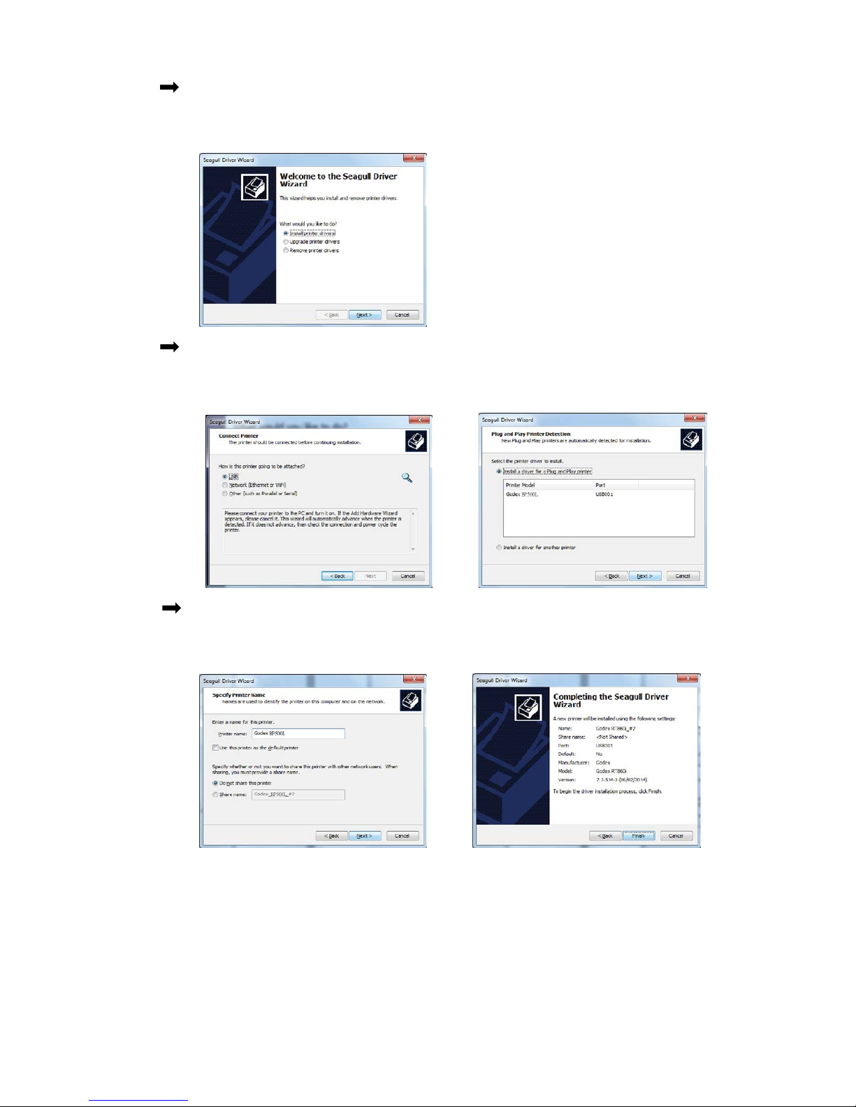
Step.04 The Driver Wizard will guide you through the installation procedure. Select "Install printer
drivers" and click “Next”.
Step.05 With a USB connection, search models such as the right diagram printer device.
Specify your printer model and click ”Next”.
Step.06 Enter the printer name (you can use default), then click "Next" to display as right
diagram. Click "Finish" button to start installation.
Page 23
18
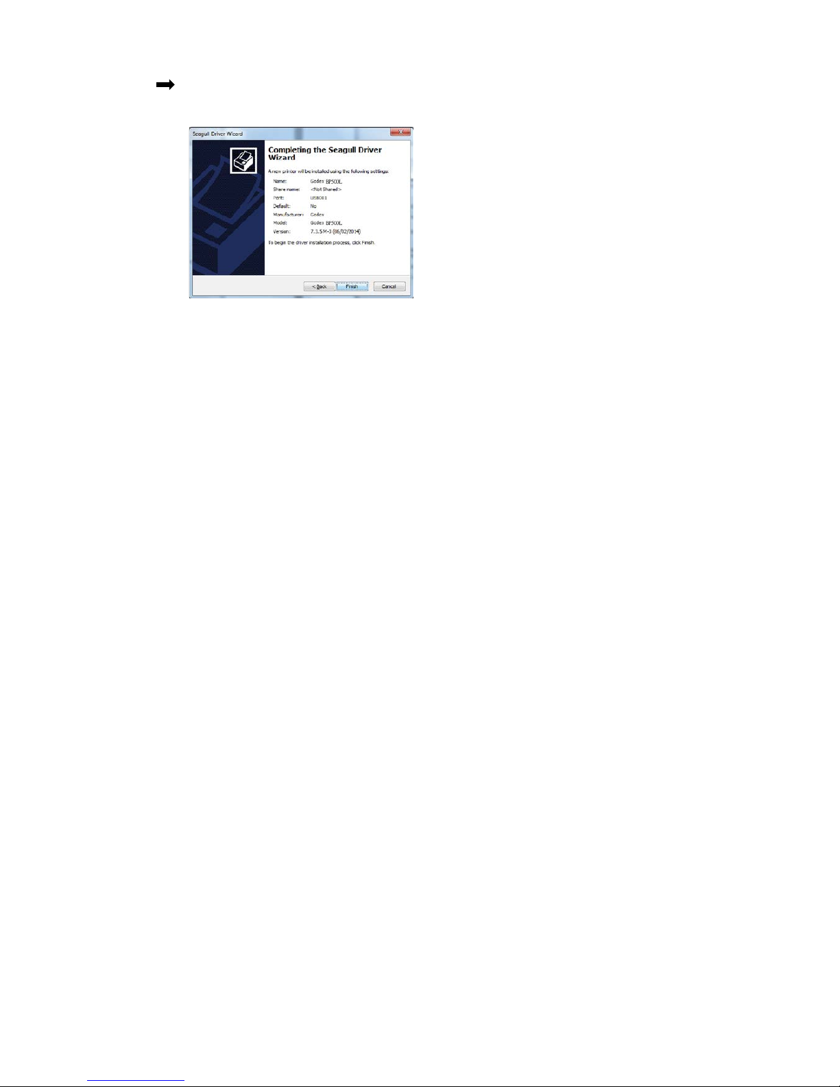
Step.07 Driver installation completed.
Page 24
19
3 Barcode Printer Operation
3-1 Barcode Printer Operation Interface
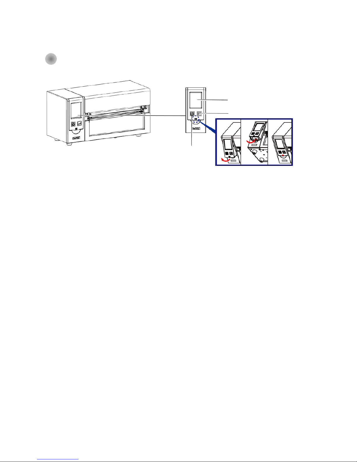
Standby key
Make sure the power switch is on, and when press the
“Standby key”, the Touch panel (LCD Display) will light up and show “Ready”. When press and hold
the “standby key” in 3 seconds, then the printer will be getting into “standby” mode.
Feed key
When you press the FEED button, the printer moves the label to the defined stop position. If you are
using continuous labels, pressing the FEED button will move label stock until you release the button
again. If you are using individual labels, pressing the FEED button will move only one label. If the label
does not stop at the correct position, please run the auto calibration (See Section 3-6. for the label
size calibration function) on the label stock.
Pause _ Feed key
If you want to pause the printing, just press the feed key then the printer will be on pause status,
besides, the LCD will show “Pause” till you press the feed key again the printer will not print any
further.
EX, if the printer is setting for 10 pages printing, when user press the feed key during the 2
nd
pages
printing, the printer will stop printing till feed key been pressed again.
Cancel Printing_ Feed key
Press and hold feed key in 3 seconds during printing, the Printer will be backed to standby mode and
LCD will display “Standby”and the printing job has been cancelled.
EX. If the printer is setting for 10 pages printing, when user press the feed key during the 2
nd
pages
printing, the printer will stop printing from the 3
rd
page and back to Standby condition since the rest
printing job has been cancelled.
Touch Panel (LCD Display)
Feed Key
Standby Key
Page 25
20
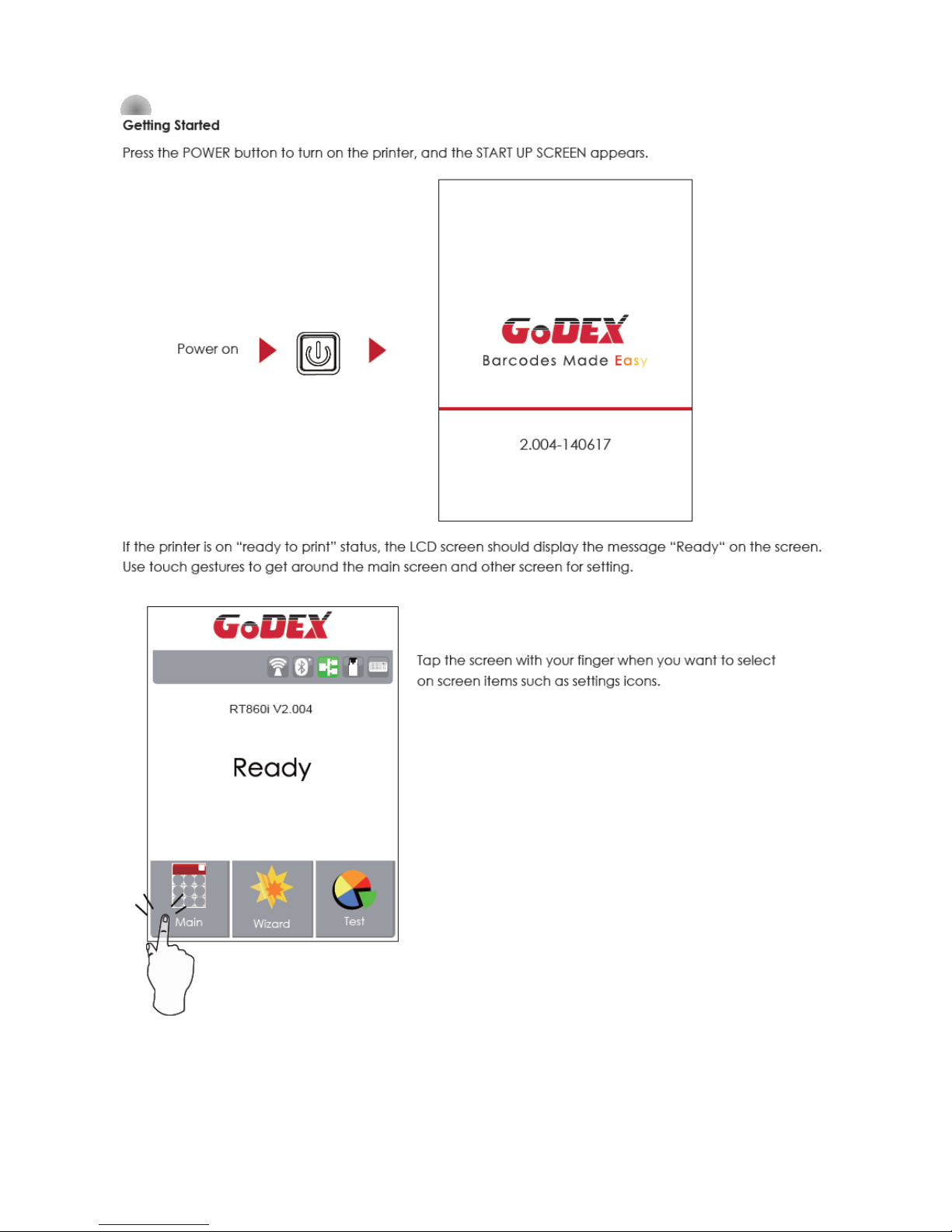
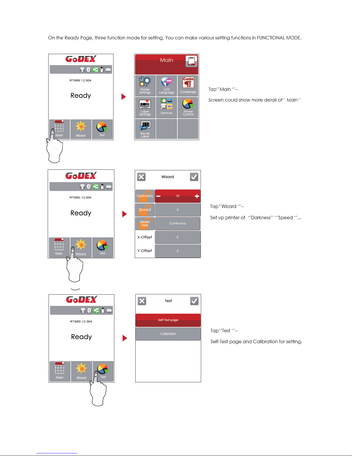
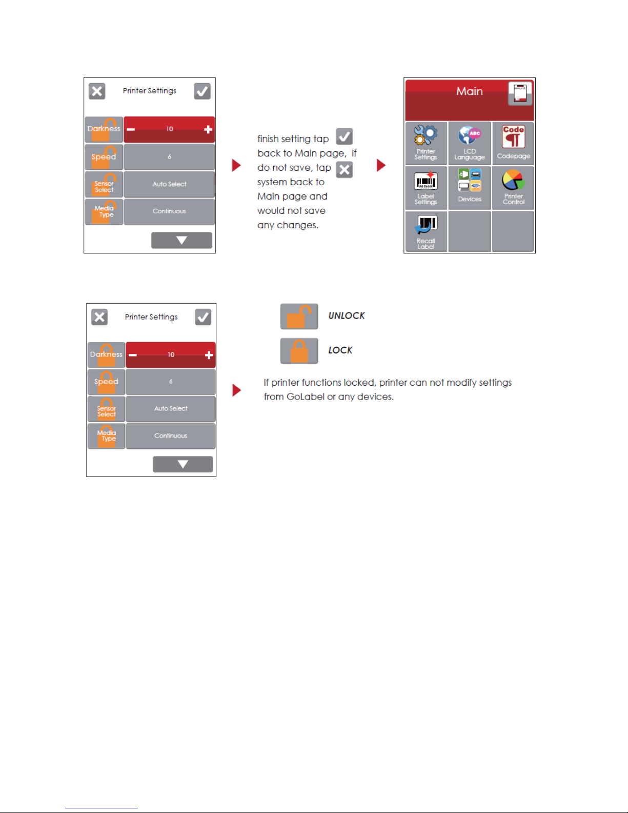
3-2 LCD Operation Introduction
Page 26
21
Page 27
22
Page 28
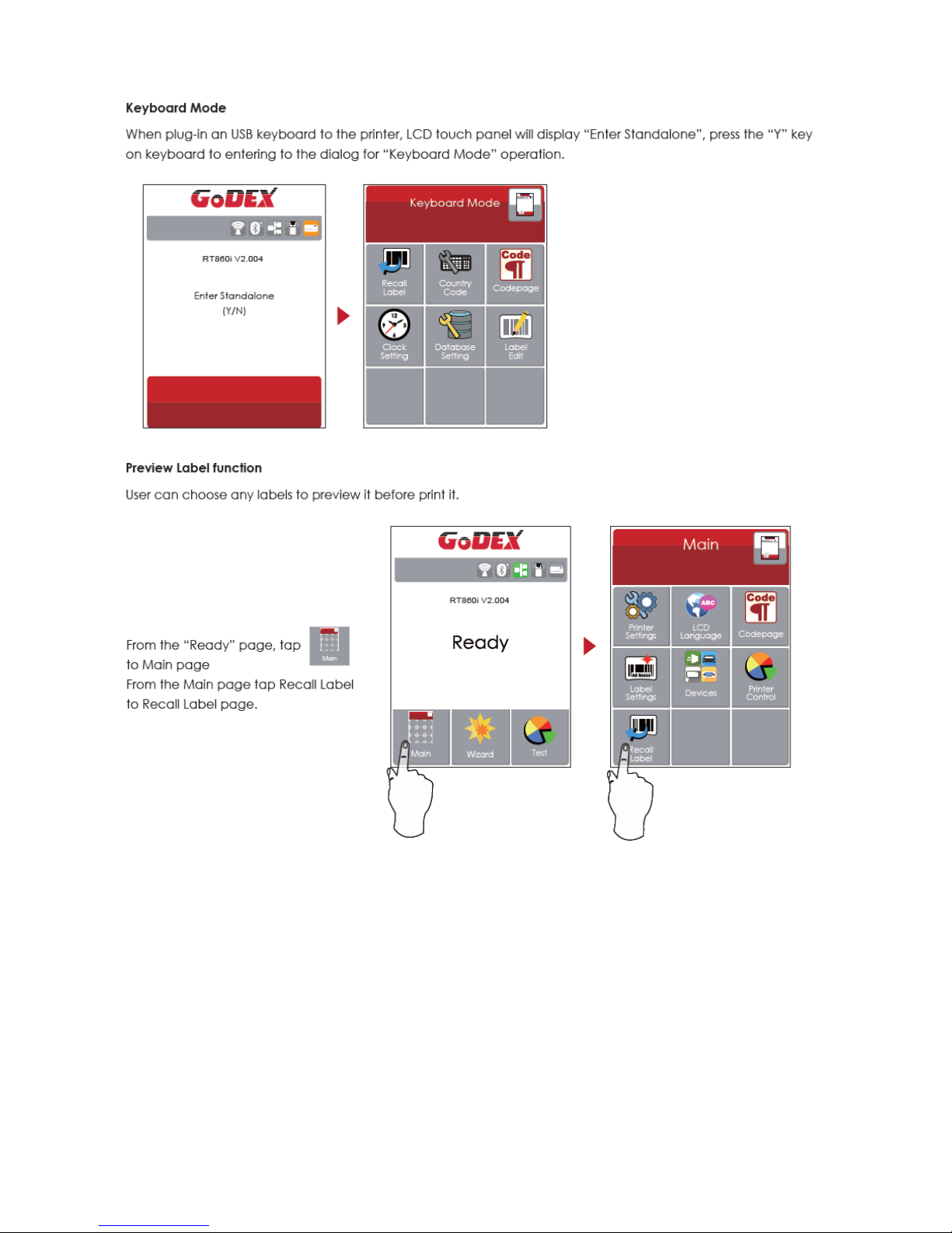
23
Page 29
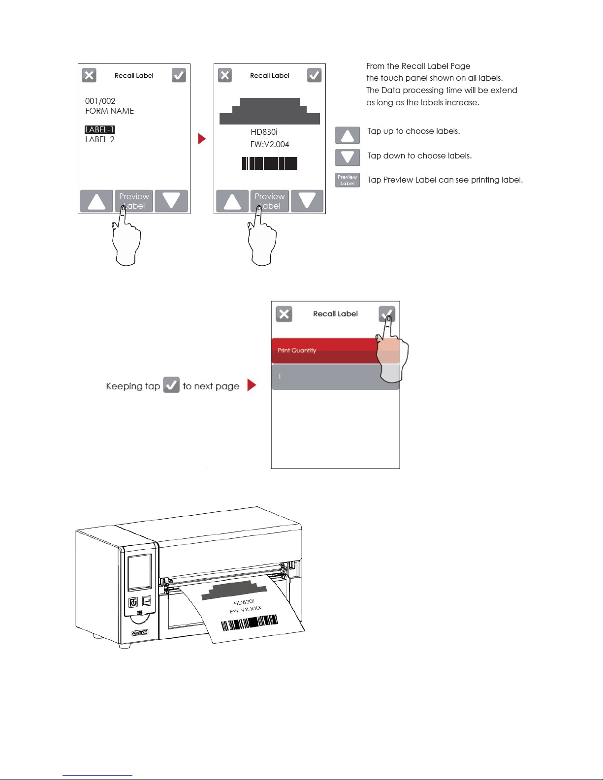
24
Label has been printed
Page 30
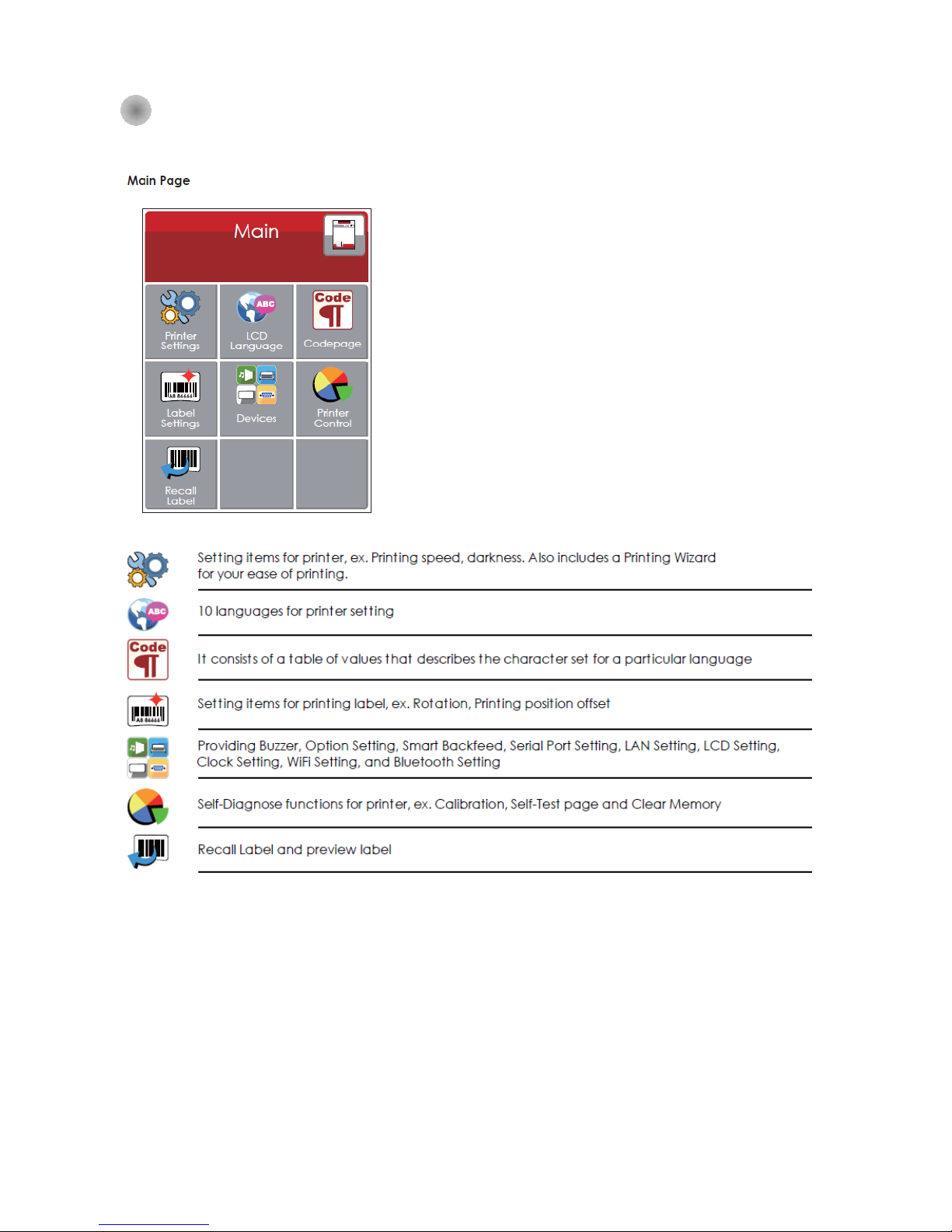
25
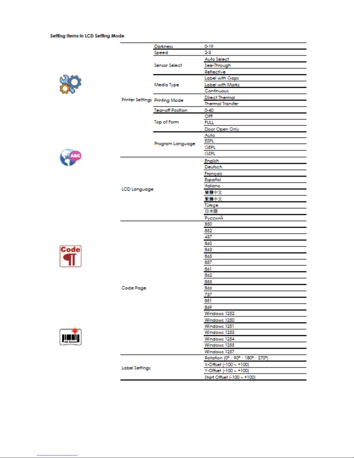
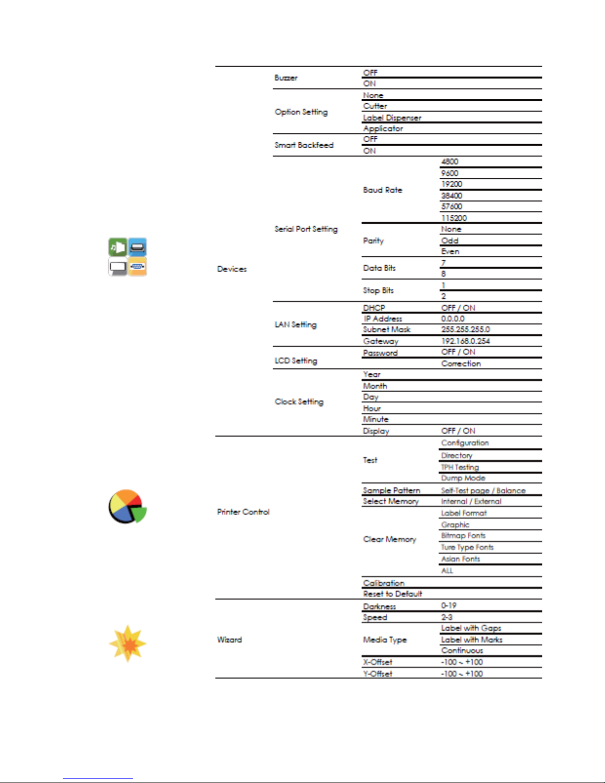
3-3 LAN Setting Operation Instruction
Main Manu
Page 31
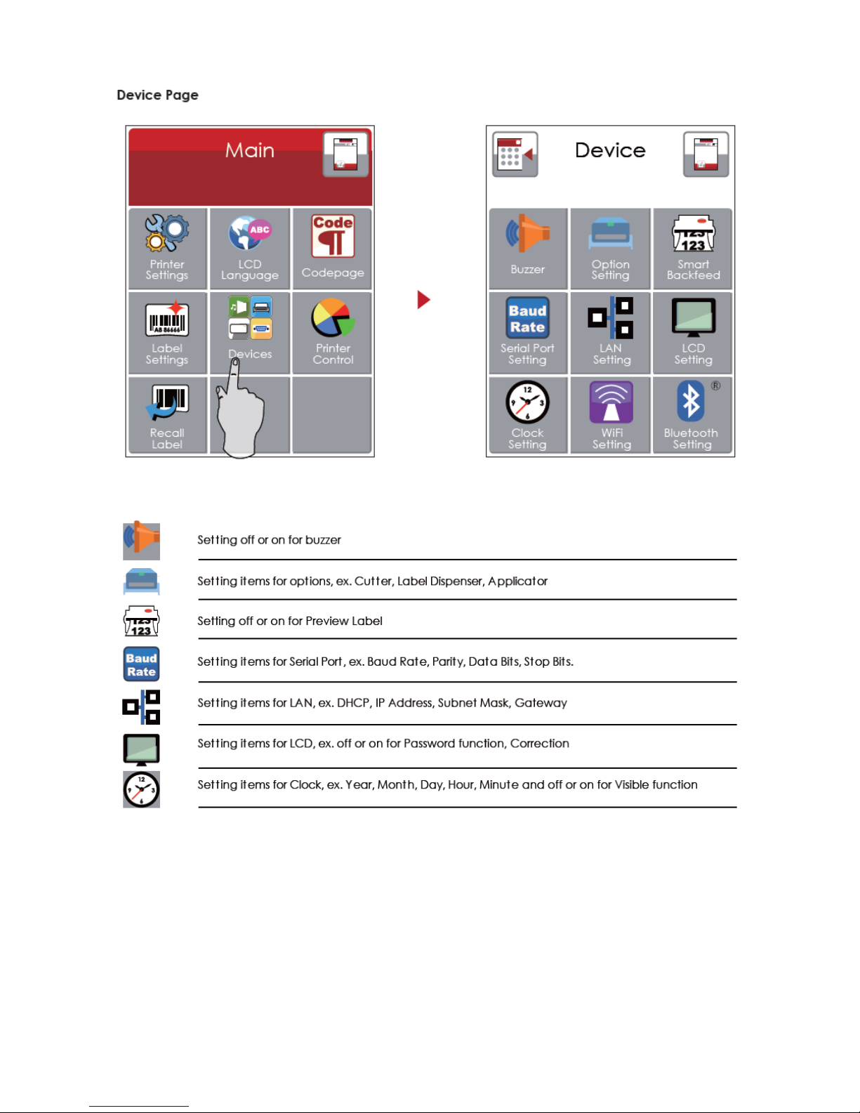
26
時間設定,例如:年、月、日、時、分、可見
Page 32
27
Page 33
28
Page 34
29
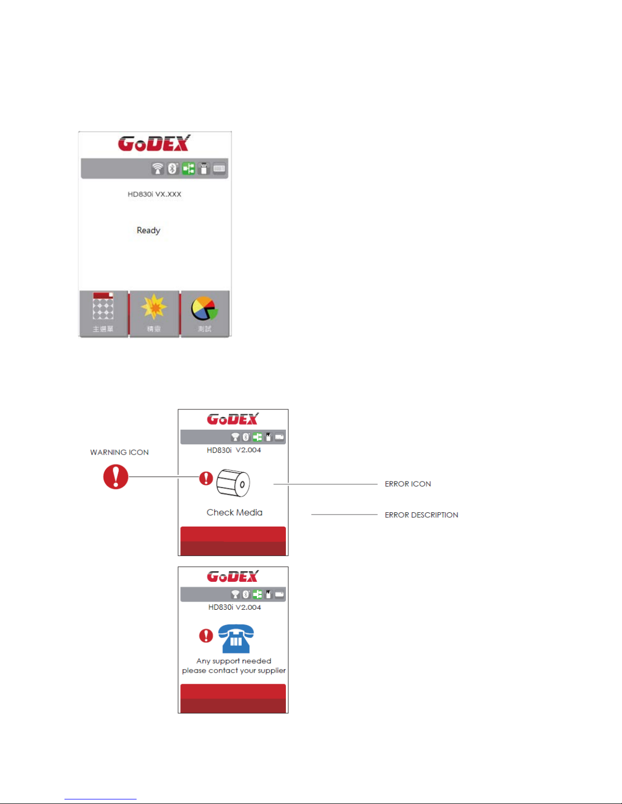
LCD Operation
When Barcode Printer is Ready, the LCD will display “Ready”
And then the printer is ready to print
If there is any error occur, there will be Error Message shows on the LCD. You could do the
trouble shooting according to or contact with the agent.
Page 35
30
3-4 Label size calibration and Self Test Page
The printer can automatically detect and store label height. That means the host computer does not
need to transmit the label height to the printer. And the self-test function lets you check whether the
printer is functioning normally. Here is how you run the label size calibration and self test.
Step.01 Check that the label stock is loaded correctly.
Step.02 Switch off the printer.
Step.03 Switch the printer on again, keeping the F EED button pres sed. When the REA DY LED starts
to flash red and the STATUS LED lights up orange, release the FEED button. The printer will
now measure the label stock and store the label height
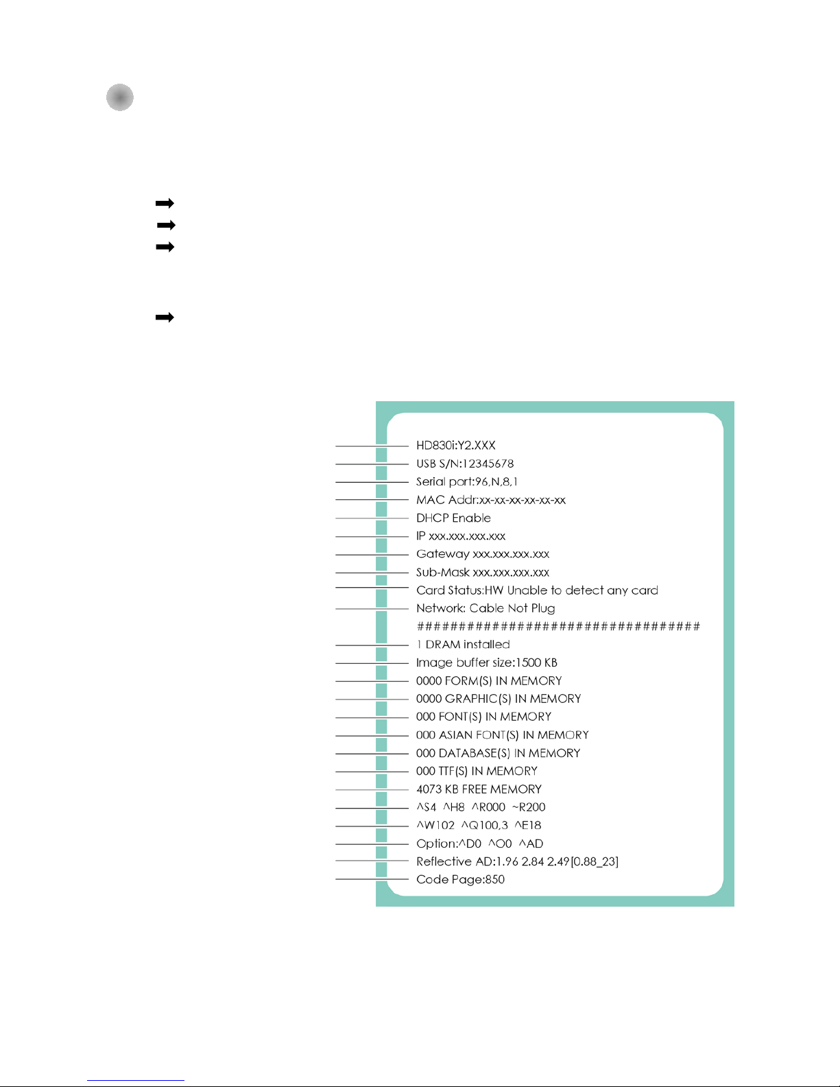
Step.04 Once the printer has successfully measured the label stock, it will print a self-test label.
The contents of a self-test printout are listed below.
(The data below is for reference only, actual result may vary according to each situation.)
Printer Model and Firmwave info
USB Port Setting
Serial Port Setting
Forms storage info
Graphics storage info
Fonts storage info
Asian fonts storage info
Database Storage info
TTF storage info
Memory Size
Speed, Darkness, Ref. Point, print direction
Media width,length, gap setting info
Options setting info
Reflective Detecting Info
Code Page Setting
Imabe Buffer Size
DRAM info
Network Status
Card Status
Sub-Mask Setting
Gateway Setting
Ethernet IP Setting
DHCP Enable or Unable
MAC Address Info
Page 36
31
Auto-Calibration
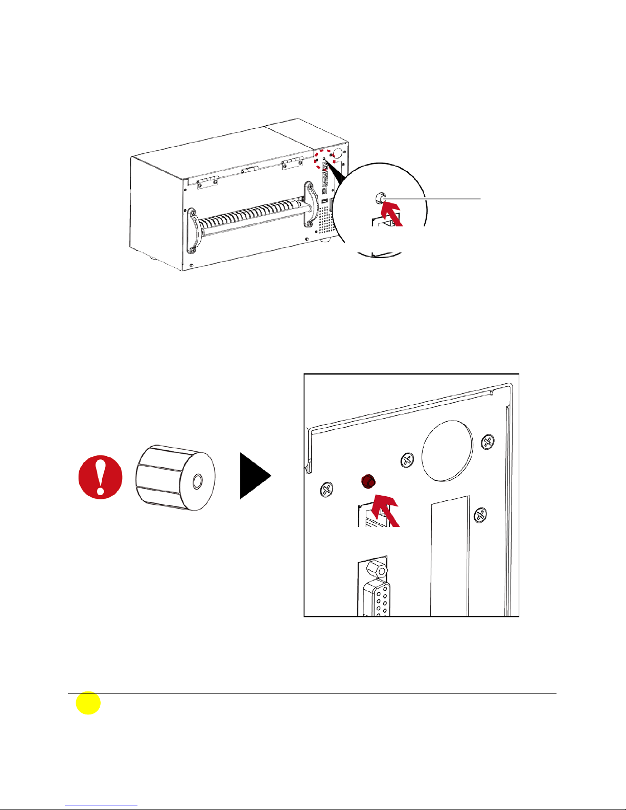
「Calibration key (C-Button)」 You could press the calibration key while media been replaced or
media error to adjust the media size.
Note
* The 「C-Button」function is same as sending command (~S,SENSOR), if run during the printing,
the (Print Job) will be deleted and run media calibration. Need to resend the print job after
calibration.
C- Button
Calibration Key
Press and hold 1~2 seconds
Hold 1~2 seconds
Press and hold the「C-Button」 around 2 seconds, the printer will run the media calibration
Page 37
32
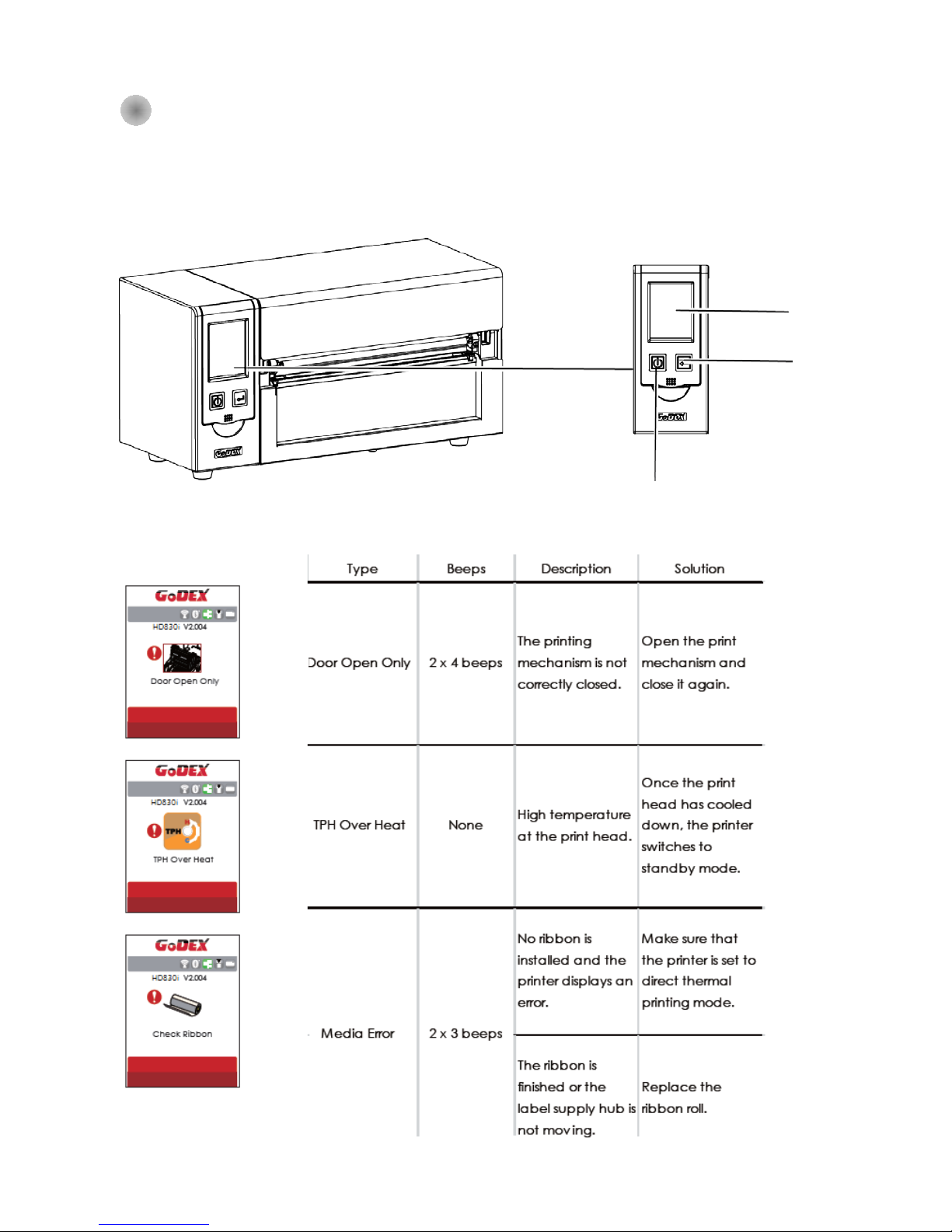
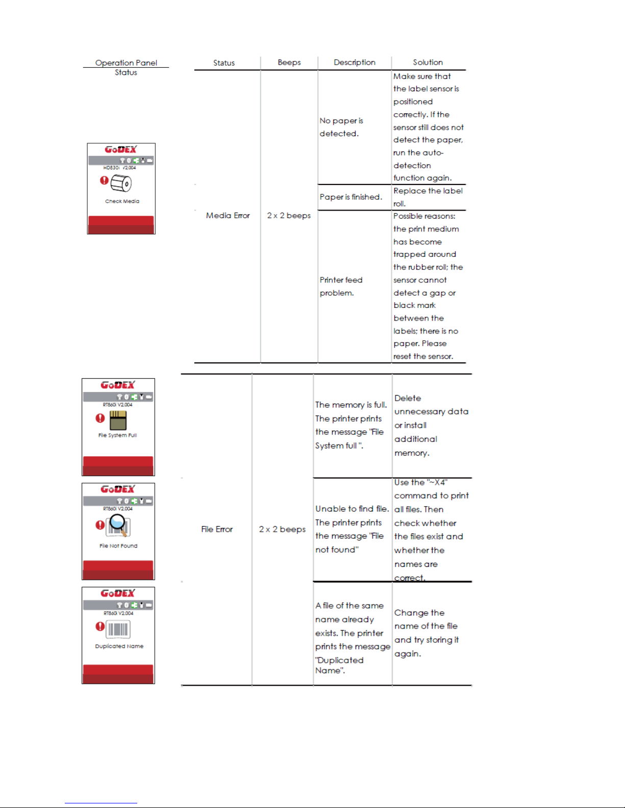
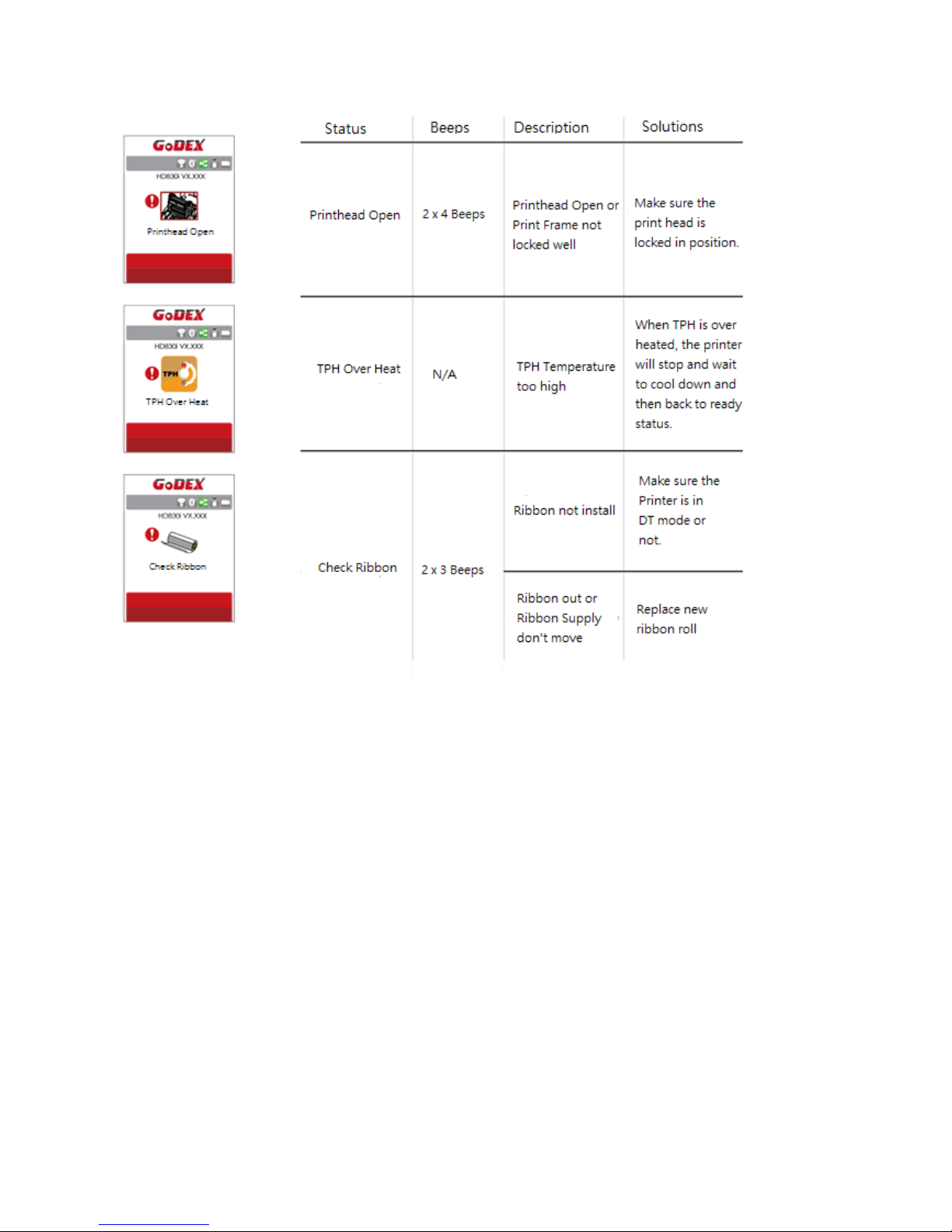
3-5 Error Message
If there is any error occurred during the printing, LCD will display the Error message and also buzzer as
warning.
Please refer to below for the error status. 。
Operation Panel Status
Operation Interface
LCD
Display
Feed Key
Power Standby Key
Page 38
33
Page 39
34
Page 40
35
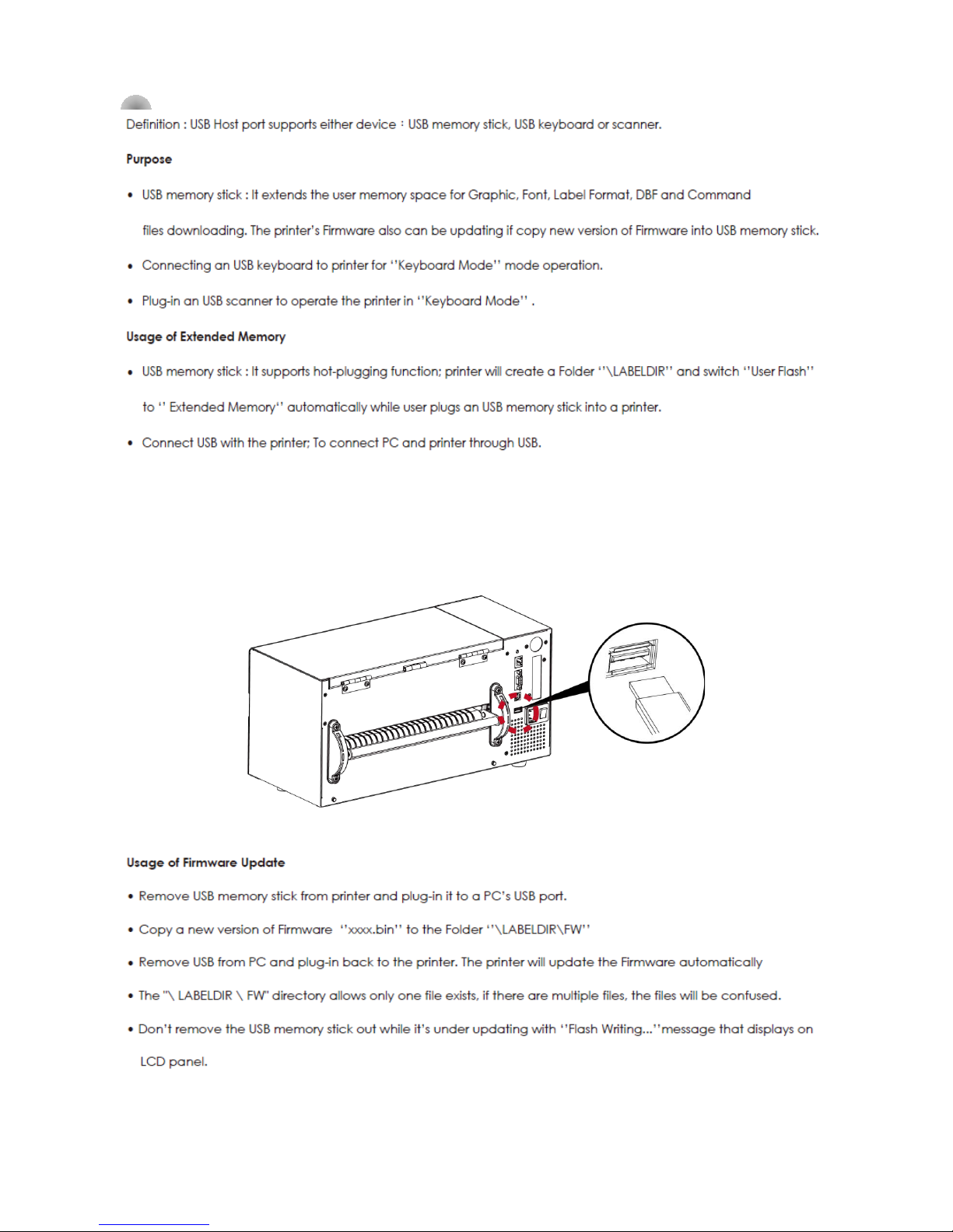
3-6 Connected with USB Devices
Page 41
36
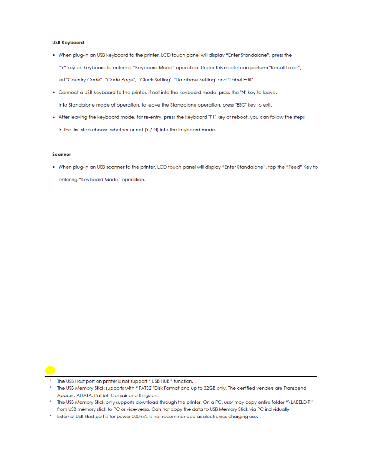
Note
Page 42
37
4 Installing the NetSetting software
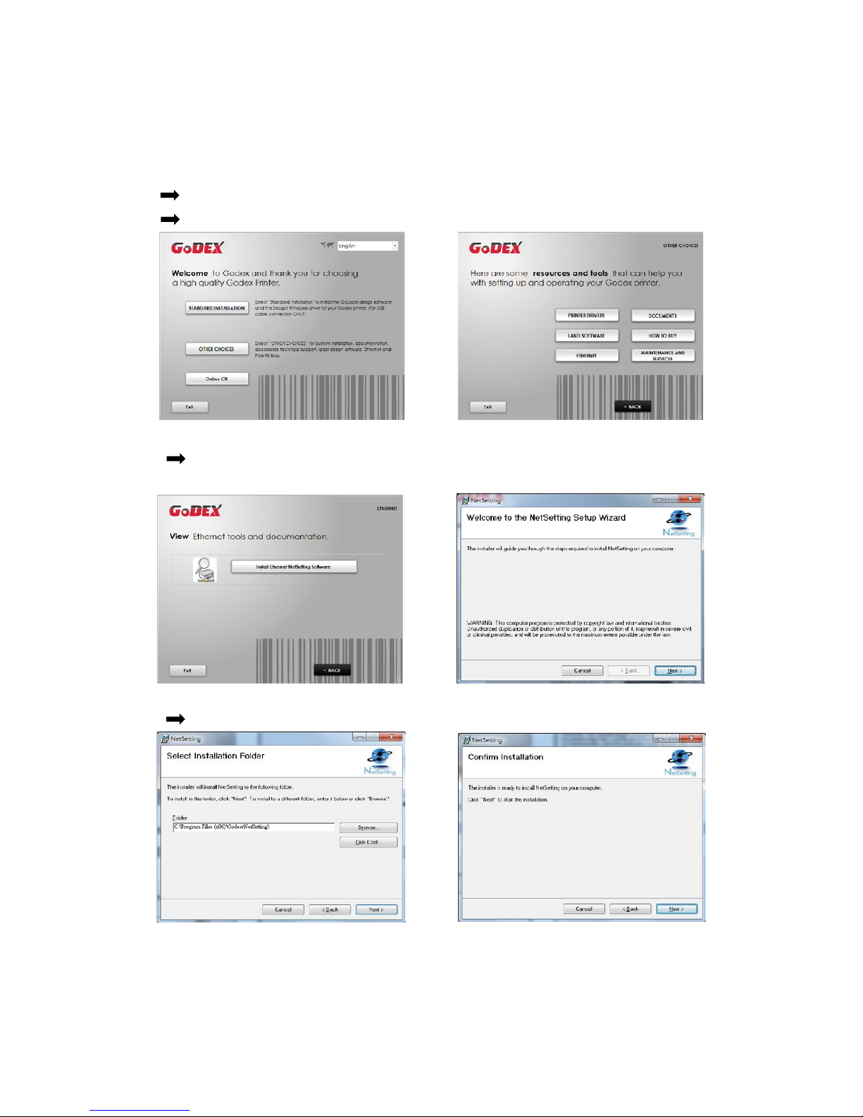
The NetSetting software is used to manage the network configurations when connecting the printer
via Ethernet port. It is available on product CD or can be downloaded from official website. To install
the NetSetting, please follow below steps.
Step.01 Insert the product CD in the CD/DVD drive, and click “OTHER CHOICES” button.
Step.02 Select “ETHERNET”.
Step.03 Click "Install Ethernet NetSetting Software", installation screen as right diagram, click
"Next".
Step.04 Specify the “Installation Folder", then click ”Next” to installing.
Page 43
38
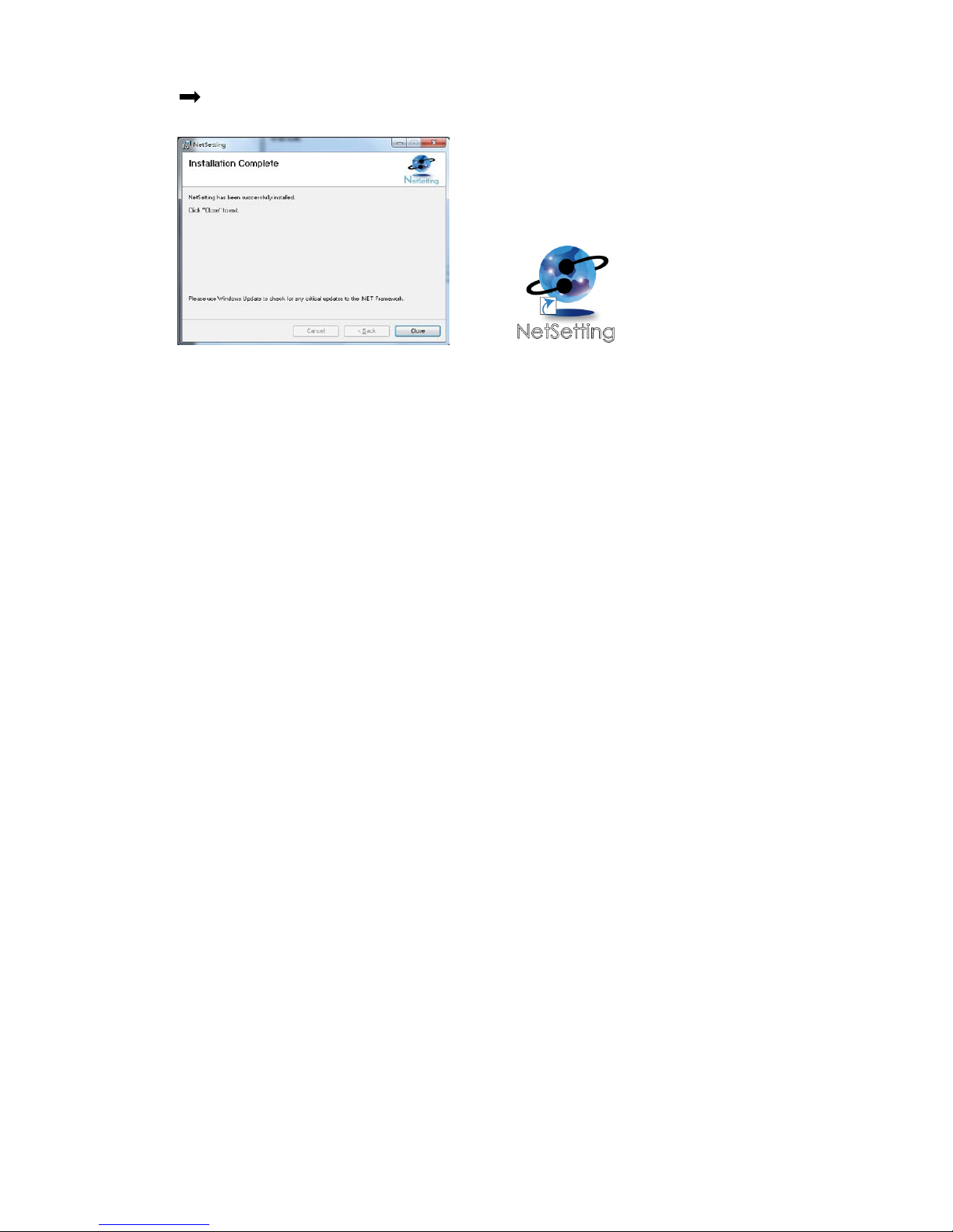
Step.05 Once the installation is completed, you will see the NetSetting icon on your desktop as
right diagram.
Page 44
39
4-2 The Interfa c e of Net Set tin g
GoDEX printer can also be used through a network connection (as a remote network printer), make
sure the printer connected to the Internet and the power cord, you can use the Interface of
NetSetting to search connected network printers.
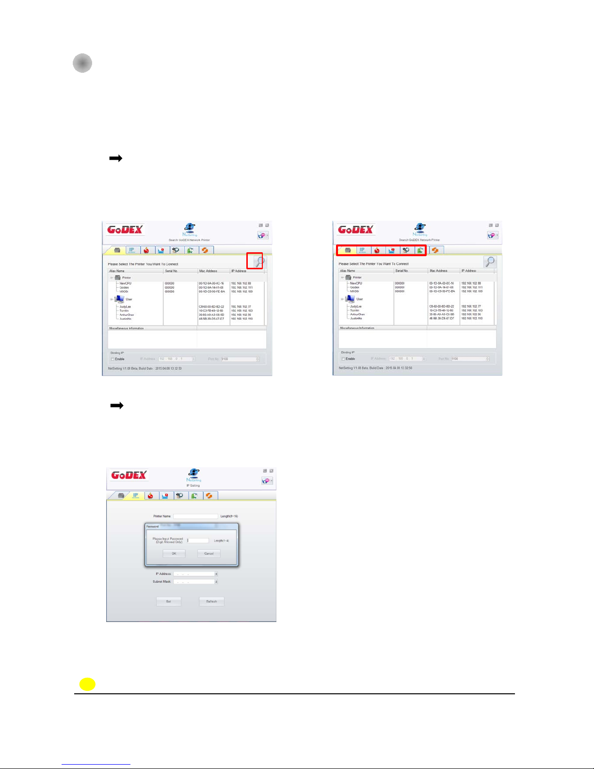
Step.01 Click the NetSetting icon to start the program, you will see the start page as left
diagram. Click the magnifier icon to search the Godex printers which are connected
via Ethernet port in you network environment (as right diagram).
Step.02 There are six tabs on the top of interface which can configure different types of
network settings. But for the data security reason, you need correct password to enter
the configuration pages.
NOTE
* The default password is “1111”, you can change the password later from the “IP Setting” tab.
Page 45
40
IP Setting
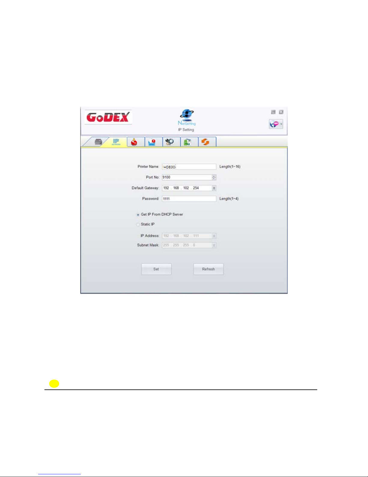
The IP Setting tab can change the printer name, Port number, Gateway setting and the password for
configuring the printer. You can also set the printer’s IP address ether by DHCP or by Static IP.
You can press “Set” button to apply the settings and “Refresh” button to refresh the setting values.
NOTE
* To fully benefit from the NetSetting software, you should be familiar with basic networking principles.
Please contact your network administrator for related network setting information.
* When enabling DHCP, if you find the IP Address as: IP = 169.254.229.88, Net mask = 255.255.0.0,
Gateway = invariable (last value), the IP Address is invalid.
Page 46
41
Alert Path Setting
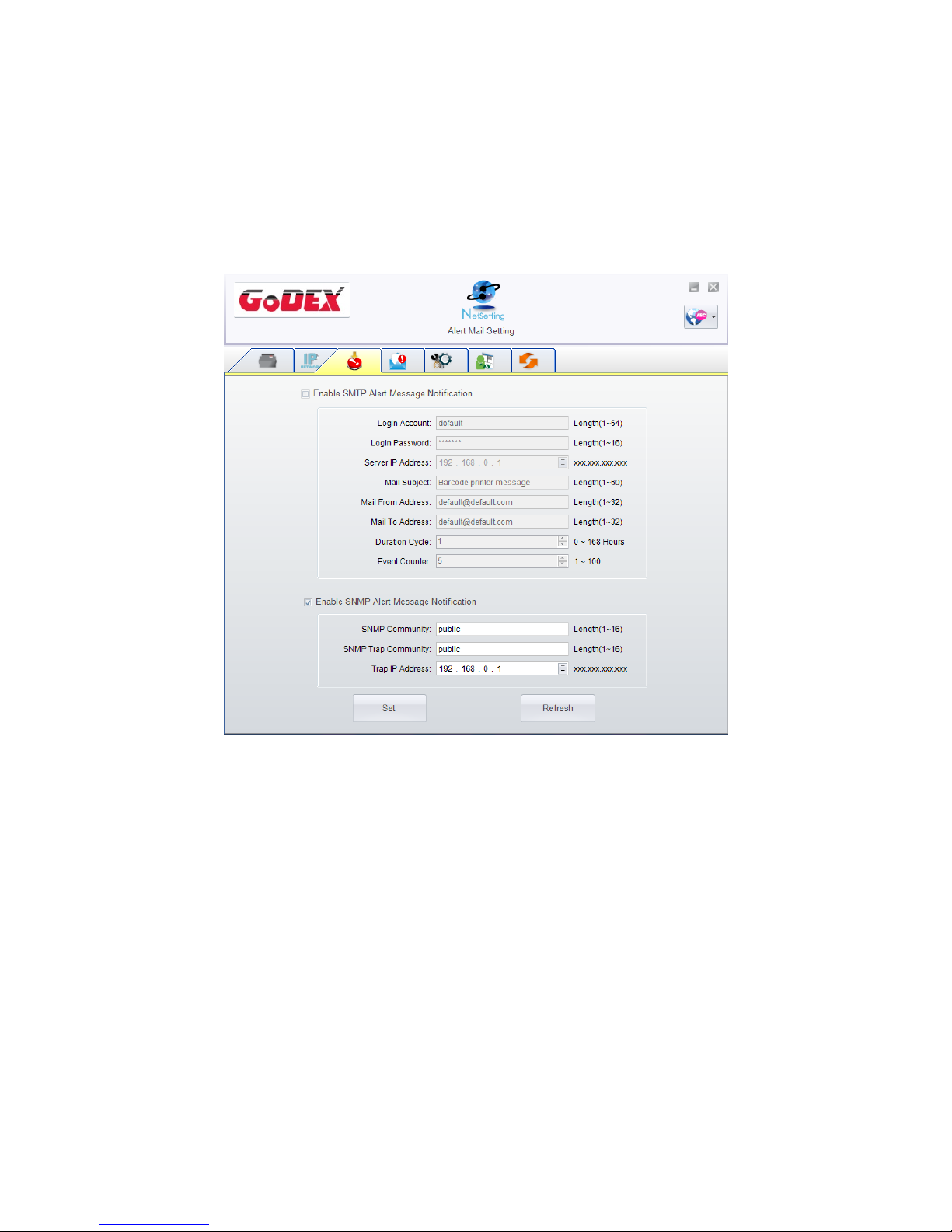
NetSetting will send the alert messages to designated mail account when the error happened on
printer. The alert messages are sent by SMTP (Simple Mail Transfer Protocol) or SNMP (Simple Network
Management Protocol). You can set or change the configurations of SMTP and SNMP on this “Alert
Path Setting” tab.
You can press “Set” button to apply the settings and “Refresh” button to refresh the setting values.
Page 47
42
Alert Message Setting
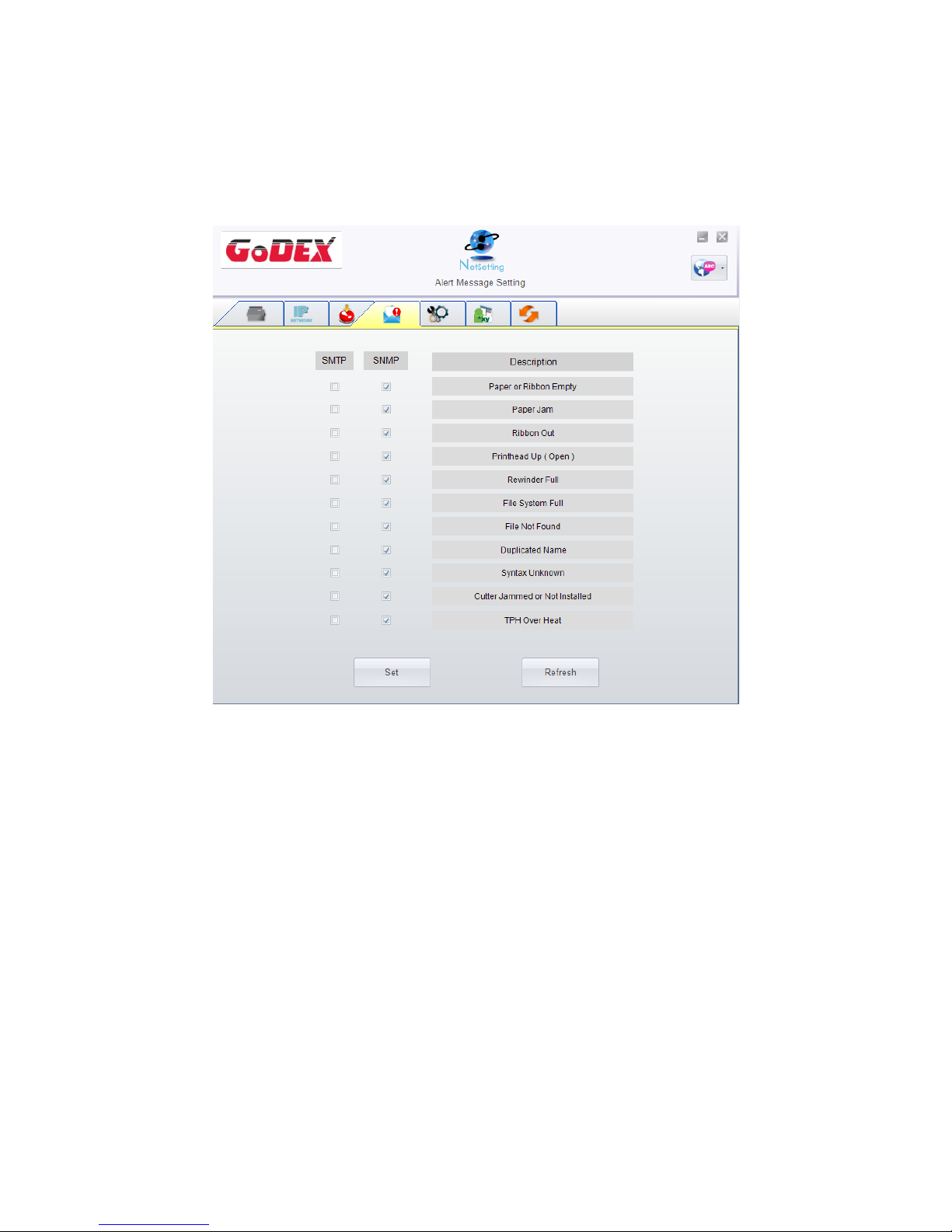
For the alert message notification function, you can decide which error cases need to be sent out to
the operator. Moreover, the alert messages can be set to be sent by SMTP, SNMP or both.
You can press “Set” button to apply the settings and “Refresh” button to refresh the setting values.
Page 48
43
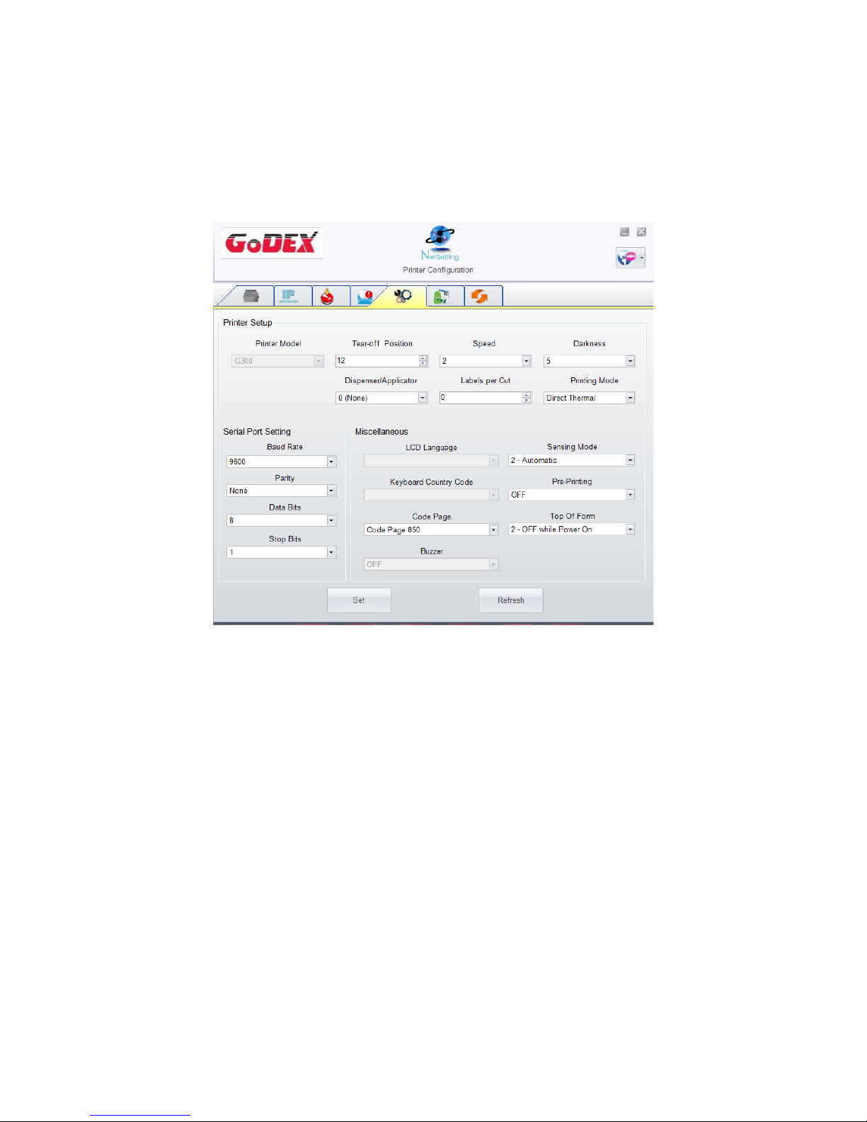
Printer Configuration
Set or change the configurations of connected printer. Most of key settings for the printer operation
can be done by this setting page.
You can press “Set” button to apply the settings and “Refresh” button to refresh the setting values.
Page 49
44
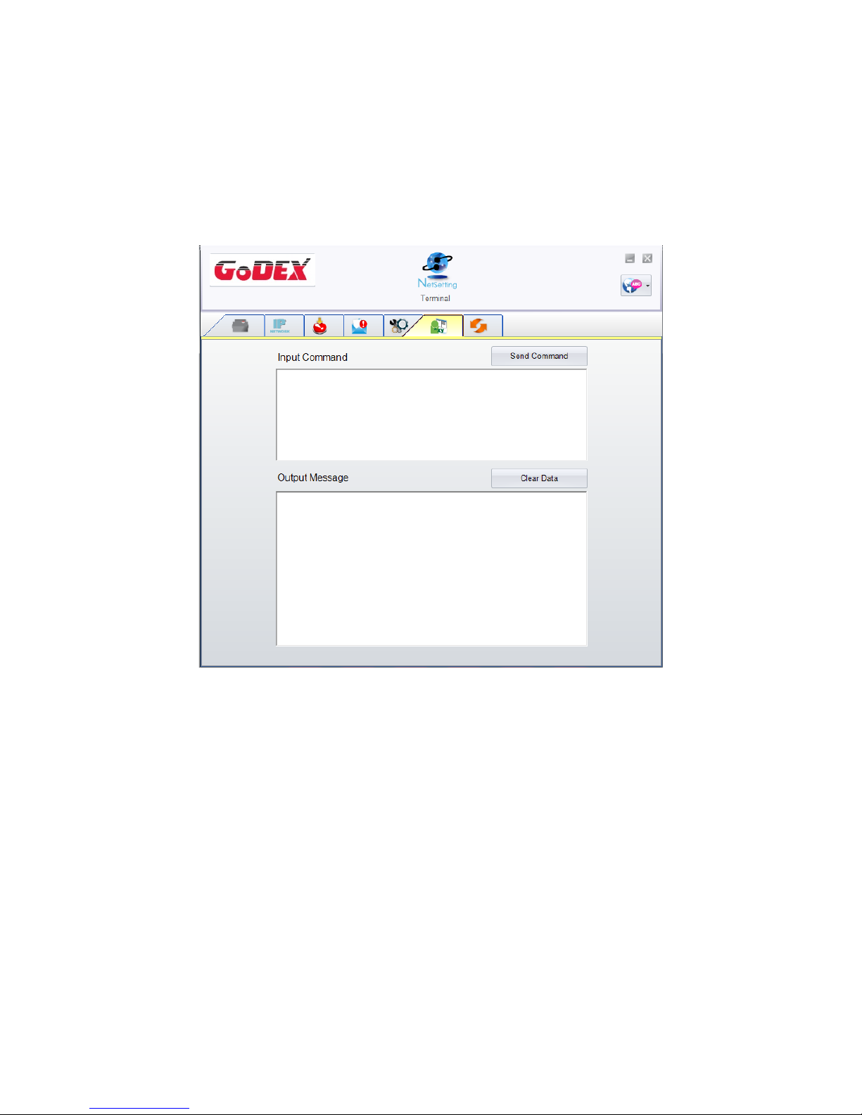
User Command
The “User Command” tab provides a communication interface for operator to control the printer.
Input printer commands in "Input Command" window and press “Send Command” button, the
commands will be sent to the printer. For some commands that will return response message, the
message will be displayed in "Output Message" window.
You can press “Set” button to apply the settings and “Refresh” button to refresh the setting values.
Page 50
45
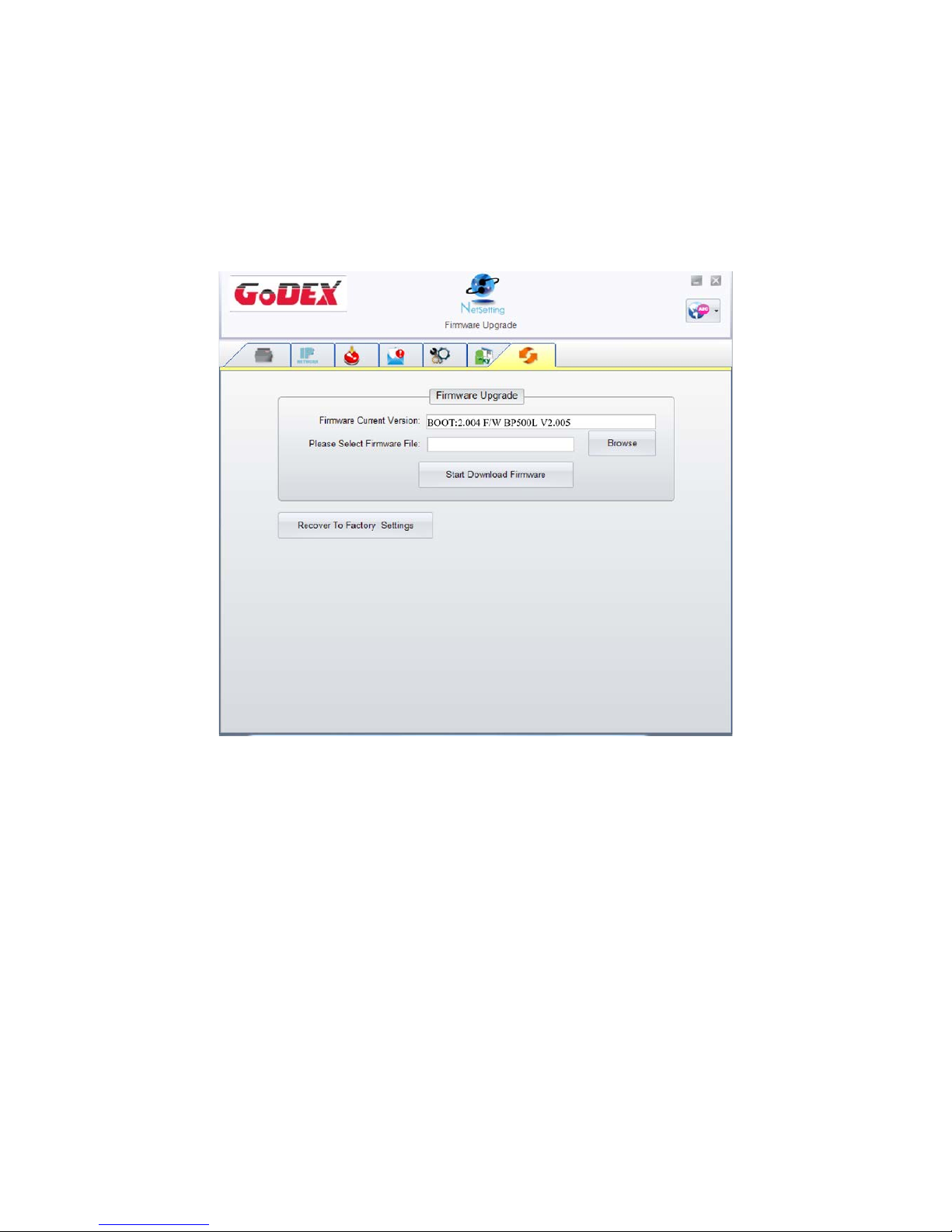
Firmware Download
On “Firmware Download” tab, the current version of printer firmware will be showed on the screen. If
you need to update the printer firmware, just specify the file location of firmware file and press “Start
Download Firmware” button. The printer firmware then can be updated remotely.
In addition to the firmware update, you can press “Recover To Factory Settings” button to restore the
printer configurations back to factory default.
Page 51
46
5 Barcode Printer Options
5-1 Pre -step for Options Installation
Before install the options, please follow the pre-Step 1
st
.
1. Power off Barcode Print er
(Please must be turn off the power before any options installation)
2. Open the Top Cover
Note
* Make sure the printer is power off status before cutter installation.
** The linerless media is not suitable for this option cutter.
Page 52
47
5-2 Cutter Installation
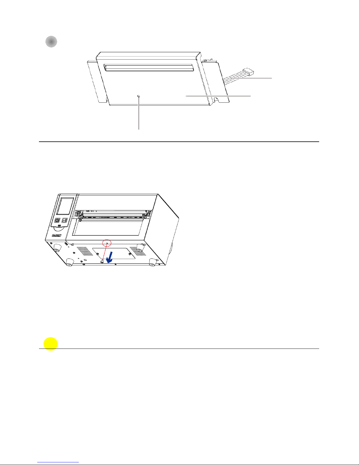
Cutter parts introduction
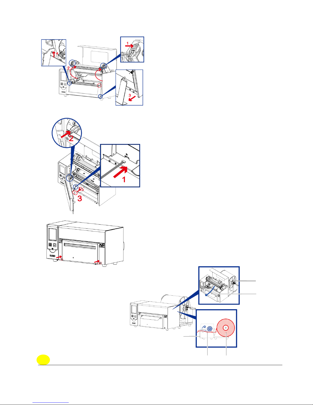
Cutter Module Installation Steps:
(Following Steps must be under printer power off condition)
Note
* Before cutter installation, make sure the printer is under power off condition or the power cord is
not plugged!
** The linerless media is not available supported.
*** The maximum cutting width is 230 mm,the minimum cutting height is 30 mm above. (If over the
range then it’s not under warranty condition)
**** Suggested Stop Position for Cutter is (^E) 29~30。
Front cover
Cutter cable
Front cover
Step 1. Disassemble the bottom case screws (Marked in Red circle)
Page 53
48
Note
* Please must make sure the power is off status before any installation for the security purpose.
Step 4. Fasten the screw in position.
Paper Feed
Direction
External Label Roll Stand
Printer
Step 2.
(No. 1) Release the TPH loc k
(No. 2) Follow the direction to ope n the print frame.
(No. 3 and 4 ) Tak e off the fron t p anel
Step 3.
( No. 1) Connecting the cutter cable into printer
(No. 2) Hook the Cutter module into position.
(No. 3) Follow the direction to put the cutter motor into position ( mark in
red ci rcle)
Assembly completely show as below
Externa Label
Roll Stand
Cutter
Feeding Direction
Page 54
49
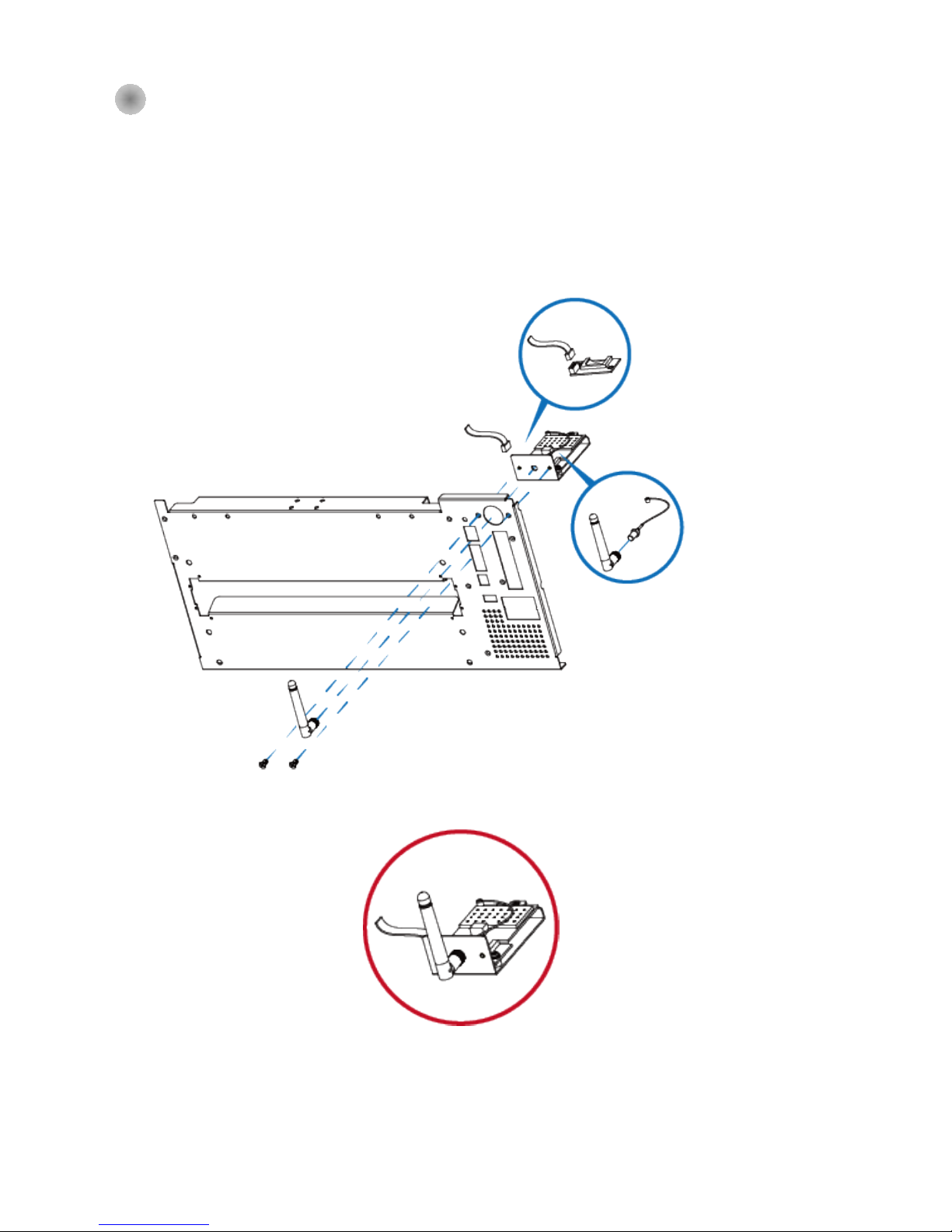
5-3 Wi-Fi Module Installation(031-H83003-000)
Step 1. Remove the rear plate
Step 2. Install the WiFi module into the rear
plate
Step 3. Connect the cable into positi on
and fasten the rear plate back
to printer
* Wi-Fi module
Page 55
50
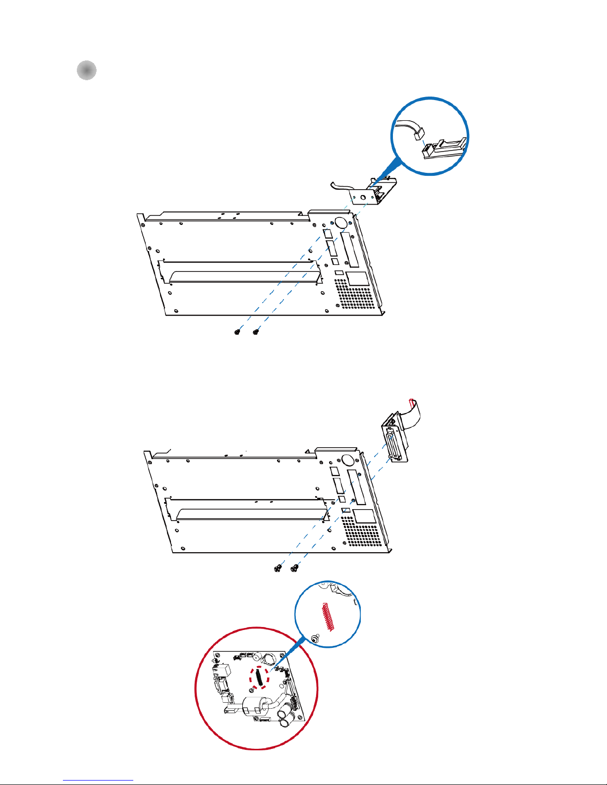
5-4 Bluetooth & Parallel port adaptor module(031-H83004-000)、(031-H83002-000)
Step 1. Remove the rear plate
Step 3. Connect the cable into
position and fasten the
rear plate back to printer
* Parallel port cable connector posit ion
Step 2. Install the Bluetooth module into
the rear plate
Step 1. Remove the rear plate
Step 2. Install the Parallel port adaptor
module into the rear plate
Step 3. Connect the cable into
position and fasten the
rear plate back to printer
Page 56
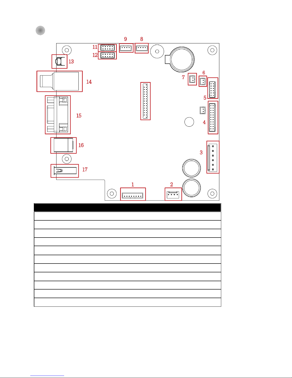
51
5-4 Main Board Connecter Position
項目 內容 項目 內容
1
Cutter & Label Dispenser 12 WiFi
2
Motor 13 Calibration Button
3
POWER 14 Ethernet Port
4
TPH 15 RS-232 Port
5
LCD panel 16 USB Port
6
Label Sensor(See-Through) 17 USB HOST
7
Door Open
8
Label Sensor (Reflective)
9
Ribbon Out Sensor
10
Parallel Port
11
BT
10
Page 57
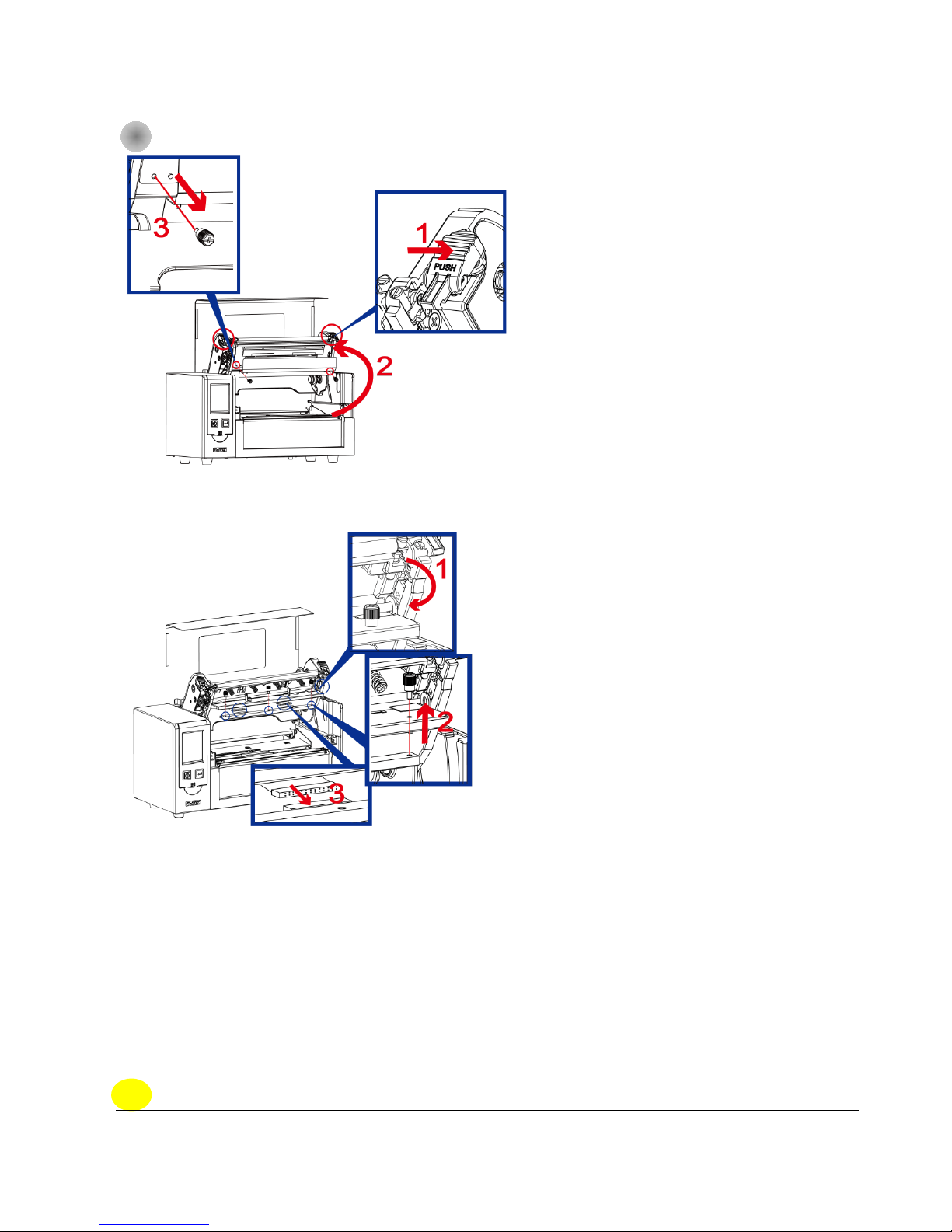
52
6 Maintenance and Adjustment
6-1 Print Head Replacement
Note
* Make sure the printer is power off status before TPH replacement.
Step 1.
(No. 1 ) Releas e t he TPH lock.
(No. 2) Follow the direction to open the Print frame.
(No. 3) Remove the TPH cover scr ews.
Step 2.
(No. 1) Follow the direc tion to roll down the TPH module.
(No. 2) Follow the direction to take out the thumb screws
( No. 3) Take off the TPH module from the connector.
Page 58
53
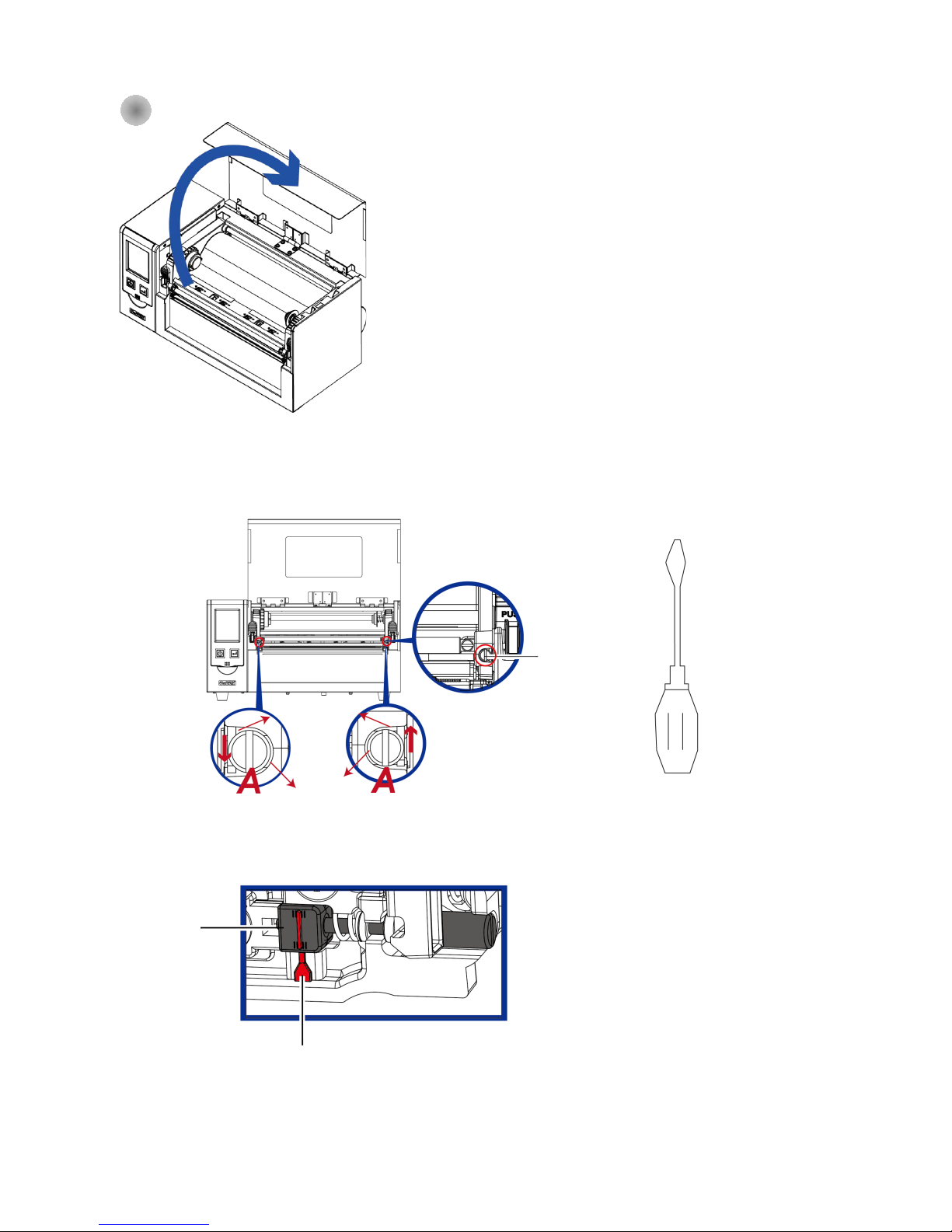
6-2 Print Line Adjustment
TPH print line adjustment:
To have good print quality in hardness or thicker media, we will
suggest to move the print line a little bit forward (paper feeding
direction) . And it will be able to apply the flat screw driver(as
above figure) turn in clockw is e o r cou n t er clockwise to rotate
the screws (A) to move back or forward the TPH position. The
adjustment screw (A) of the left and right side of the print head
position adjustment should be adjusted so that the print line is
parallel to the center line of the roller. Adjust the screw (A) to
rotate one turn, the print hea d displacement stroke is 0.5mm, it is
recommended to adjust t h e w a y p rog res sive, each time to
adjust the 1/4 turn to confirm the print quality situation.
(A) Turn the adjustment screw (A) on the left and right sides to
the position where the adjustment line is aligned with the
indicating line, and return to the original position and then adjust
it again according to the above adjustment method.
1. Lift up the top cover.
Print Line
Adjustment Screw
Print lin e Adj u st
Indication Line
2. Use the flat screw driver
Page 59
54
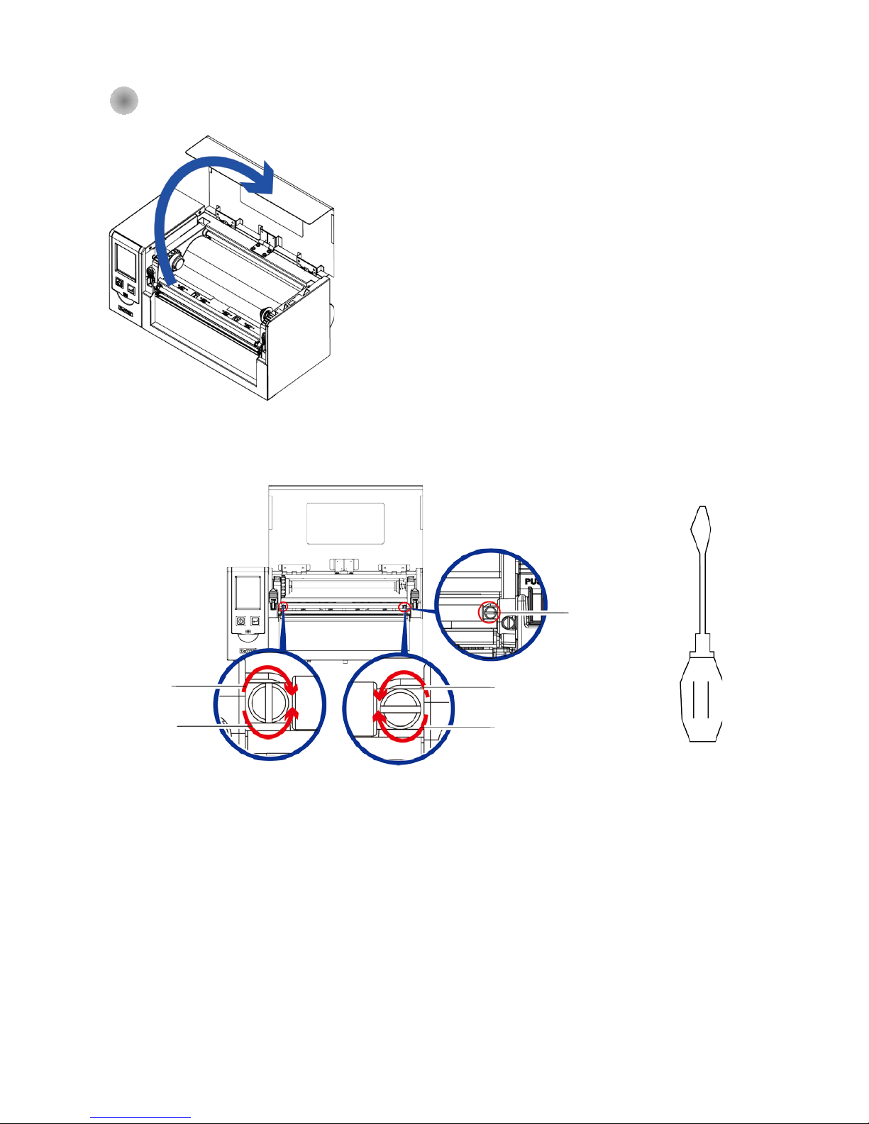
6-3 Ribbon Tension Adjustment
Counter Clockwise : Loosen the tension
Clockwise: Tighten the tension
Clockwise : Tighten
the tension
Counter Clockwise:
Loosen the tension
1. Lift up the top cover
2. Use the flat screw driver
Tension Adjust Screw
Page 60
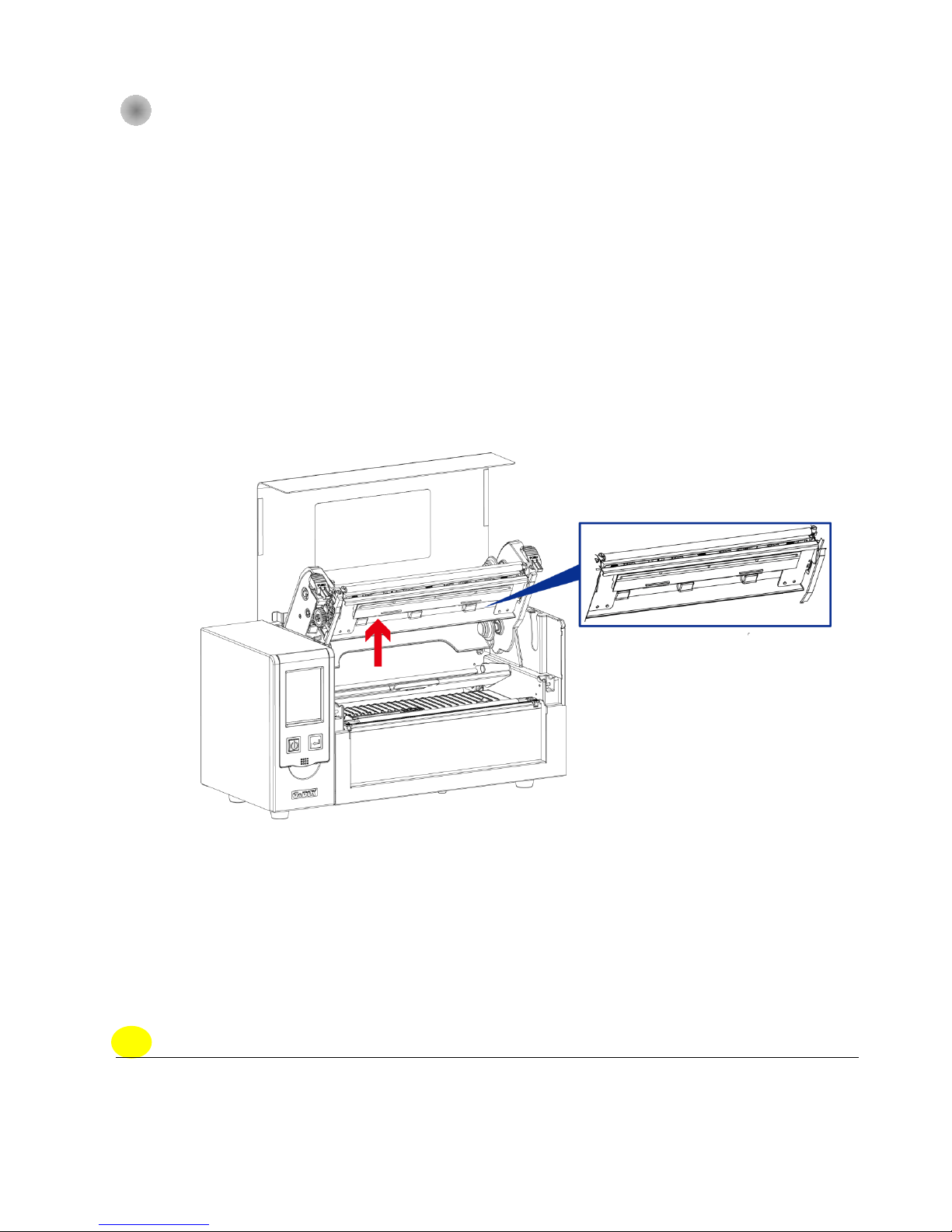
55
6-4 Print Head Cleaning
Dirt on the print head or ribbon, or glue residue from the label stock may result in inadequate print
quality. The printer cov er must there fore always be clo sed d uring pr inting. K eeping dirt a nd dus t away
from the paper or labels ensures a good print quality and a longer lifespan of the print head.。
Print Head Cleaning Steps
Step.01 Switch off the printer.
Step.02 Open the printer cover.
Step.03 Release the printing mechanism and lift it.
Step.04 Remove the ribbon
Step.05 To remove any label residue or other dirt from the print head (see red arrow), please use
a soft lint-free cloth dipped in alcohol
Note
* The print head should be cleaned once a week.
* * Please make sure that there are no me tal f ra g ments or o ther har d par ticles o n the so f t c loth u se d
to clean the print head.
Page 61
56
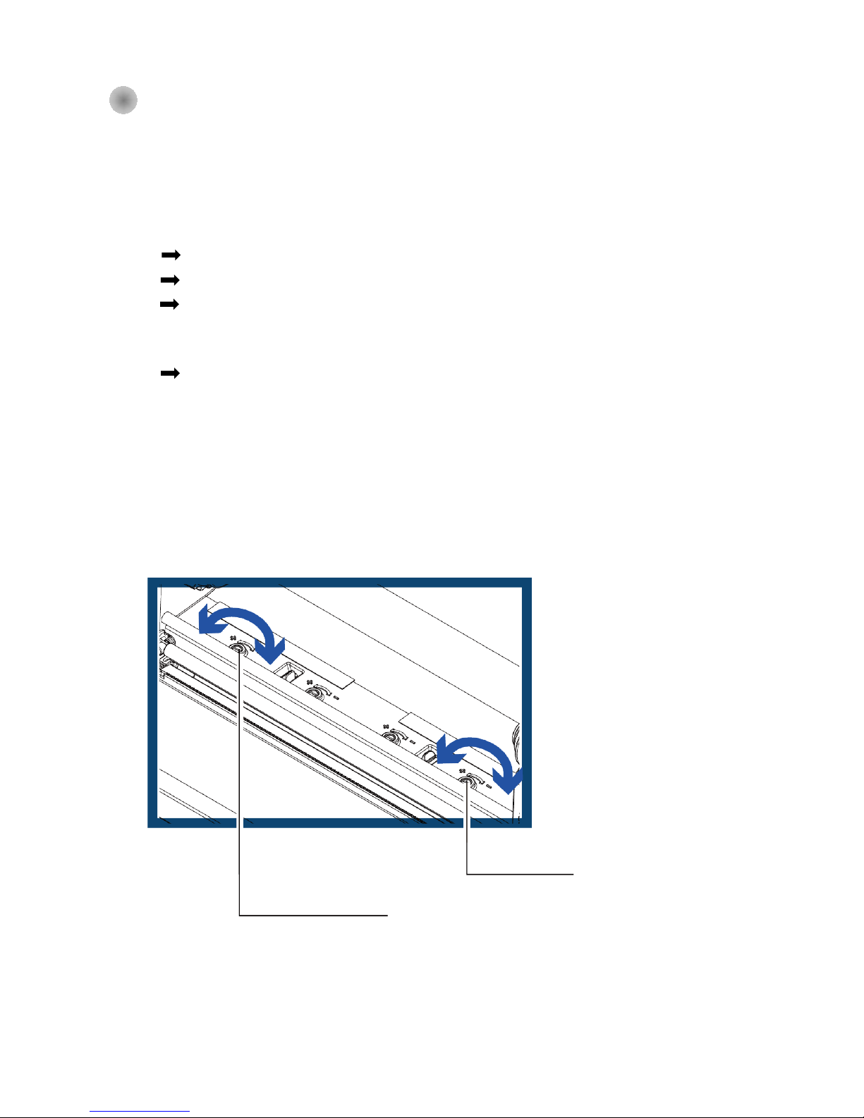
6-5 Print Head Pressure Adjustment
When printing on special media (with varying material thickness), the print quality may suffer. You will
then need to adjust the print head pressure.
Adjustment Steps
Step.01 Open the printer cover.
Step.02 Remove the ribbon.
Step.03 Use a screw driver and slowly turn the adjustment screws for the pr int head to in creas e o r
reduce the print head pressure. Do not screw it hard, otherwise the machine will be
broken.
Step.04 Turn the adjustment screws according to actual position which is unsuccessful printed.
Turn towards + (Plus) indicates : T he pressu re is increas ed;Turn towards – (Minus) indicates:
The pressure is reduced.
。
SCREW ( RIGHT )
Screw for adjusting the print head
pressure on right side
SCREW ( LEFT )
Screw for adjusting the print head
pressure on left side
Page 62
57
6-6 Ribbon Wrinkle Adjustment
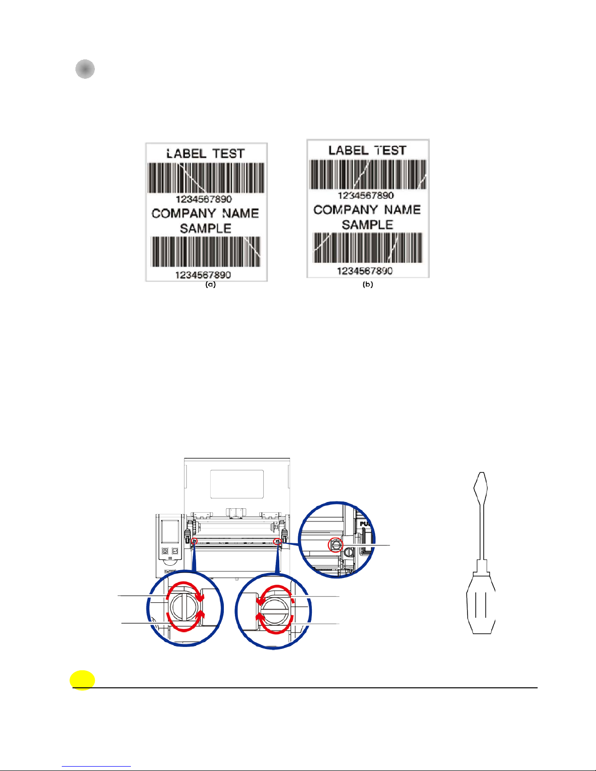
To keep track of the cha nge in print quality, you shou ld adju s t the scr ews b y half a tur n at a time . P rin t
a test page. If there is no improvement in the print result, turn the screw by another half turn. Do not
turn the adjustment screw more than two full turns.
Note
* If you adjust the screw by more than two full turns, the paper feed may no longer function
correctly. In that case, unscrew the ribbon shield screws fully and restart the adjustment process.
Ribbon tension
adjust screw
Clockwise: Tighten
tension
Counter Clockwise :
Loosen tension
Counter Clockwise :
Loosen tension
Clockwise: Tighten
tension
The use of different ribbon mater ials may caus e wrinkling of the r ibbo n, whic h in turn aff ects the
print result as illustrated by the examples in (a) and (b). To change the print quality, you can
adjust the ribbon shield screws. If your print result looks like the example in (a), you need to turn
Page 63
58
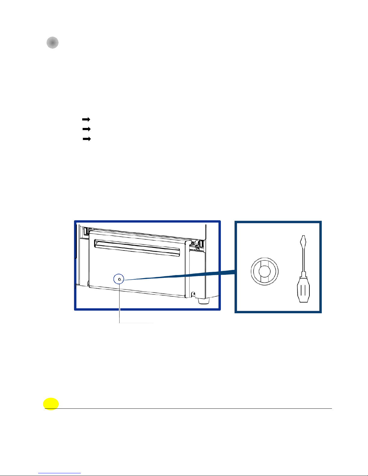
6-7 Cutter Error Trouble Shooting
While using the cutter, paper jams may occur. Please follow the below steps to clean the paper jam.
A socket head screw for adjusting the cutter is located on the bottom of cutter module, as shown in
below illustration.
Guillotine Cutter
Cleaning Steps
Step.01 Switch off the printer.
Step.02 Use a Philips screwdriver to turn the socket head screw and release the knife.
Step.03 When you have cleared the paper jam, switch on the printer again. The cutter will
automatically reset.
Note
* Make sure power is off status before repairing.
** Labels should be at least 30 mm high to ensure correct functioning of the cutter。
Adjusting position of the cutter
Page 64
59
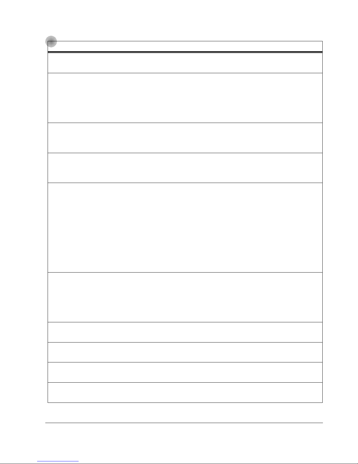
6-8 Trouble Shooting
Problem Solution
The printer is switched on but the display
does not light up.
♦ Check the power supply.。
One or both LEDs light up red and printing is
interrupted.
♦ Check the software settings (driver settings) or command
codes.
♦ Look for the erro r a le rt in t he table in Section 3-
3 Error alerts .
♦
Check whether the cutter is functioning normally and
whether it is cutti ng at all. (Only if a cutter is installed.)
The label stock passes through the printer
but no image is printed.
♦
Please make sure that the label stock is loaded the right
way up and that it is s uitable material.
♦ Please make sure that the ribbon is loaded correctly.
The label stock jams during printing.
♦
Clear the paper jam. Remove any label material l eft on the
thermal print head and clean the print head using a soft
lint-free cloth dipped in alcohol.
There is no printed image on part of
the
label or the image is blurred.
♦ Check the thermal print head for dust or othe r dirt (label
material or ribbon residue).
♦ Check for errors in the application software.
♦ Check the ribbon for wrinkles.
♦ Check the power supply.
♦ Run a self test (Section 3-2 )
and check the test print pattern
to see whether the print head prints over the entire width of
the medium.
♦ Check the quality of the print medium.
The printed image is positioned incorrectly
or a label is missed out during printing.
♦ Run the Label size calibration function. (Section 3-2)
♦ Check the label height setting.
♦ Check whether there is paper or dust covering the
sensor.
♦ Check the paper guide settings.
The cutter does not cut off the labels in a
straight line.
♦ Check whether the label stock is positioned str a ight.
The cutter does not cut off the labels
completely.
♦ Check whether the label is more than 0.2 mm thick.
When using the cutter, the labels are not fed
through or cut off incorrectly.
♦ Check whether the cutter has been correctly installed.
♦
Check whether the paper guides are functioning correctly.
The label dispenser is not functioning
normally.
♦ Check whether there is dust on the label dispenser.
♦ Check whether the label stock is positioned correctly.
NOTE
If any problems occur that are not described here, please contact your dealer.
Page 65
60
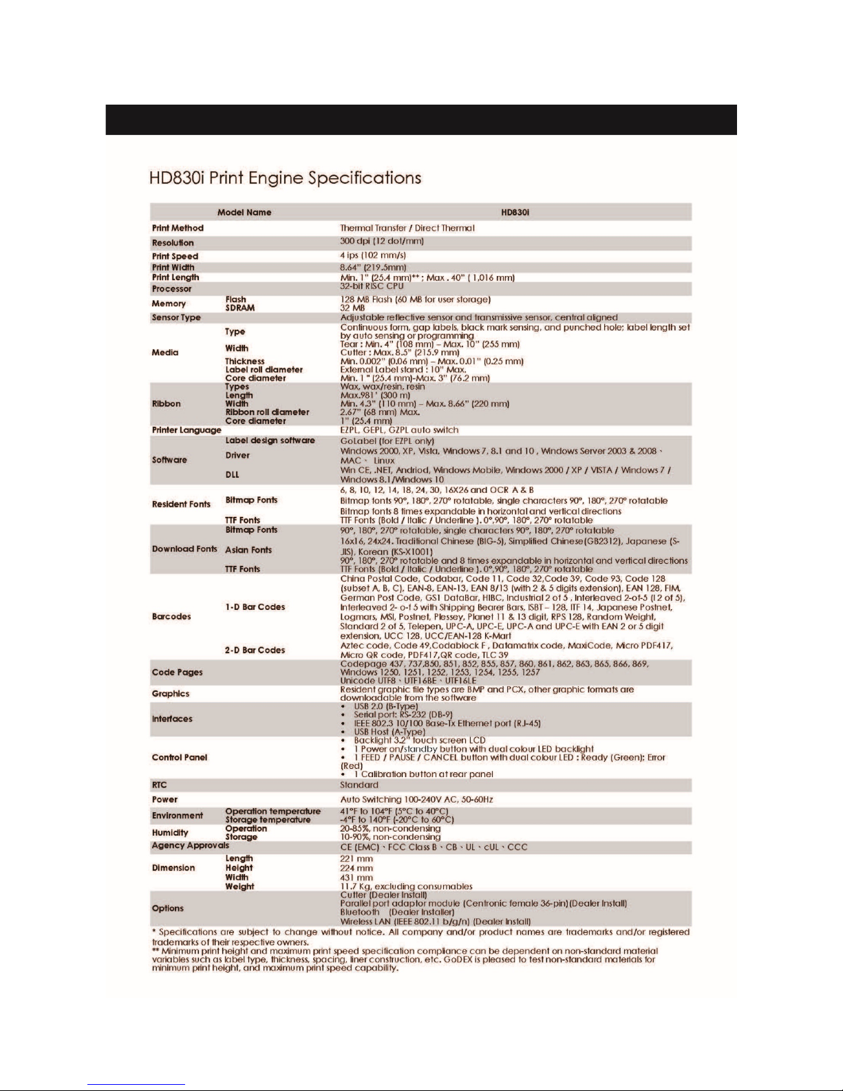
Appendix - Printer Specification
Page 66
61
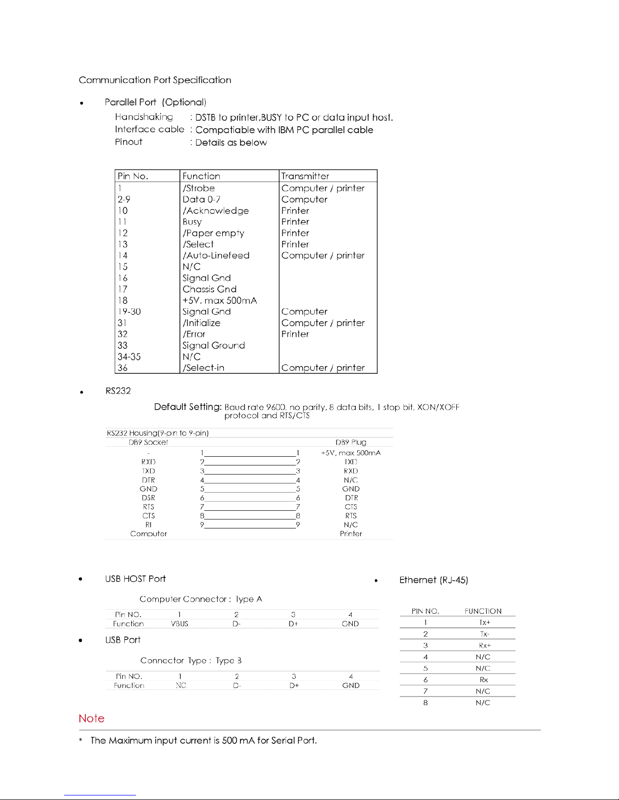
Appendix - Communication Port Specification
Page 67
62
Page 68
63
Page 69
64
Page 70
65
Page 71
66
Page 72
67
Page 73
68
Page 74
69
Page 75
70
Page 76
71
Page 77
72
Page 78
73
Page 79
74
Page 80
75
Page 81
76
Page 82
77
Page 83
78
Page 84
79
Page 85
80
Page 86
81
 Loading...