

Page 1
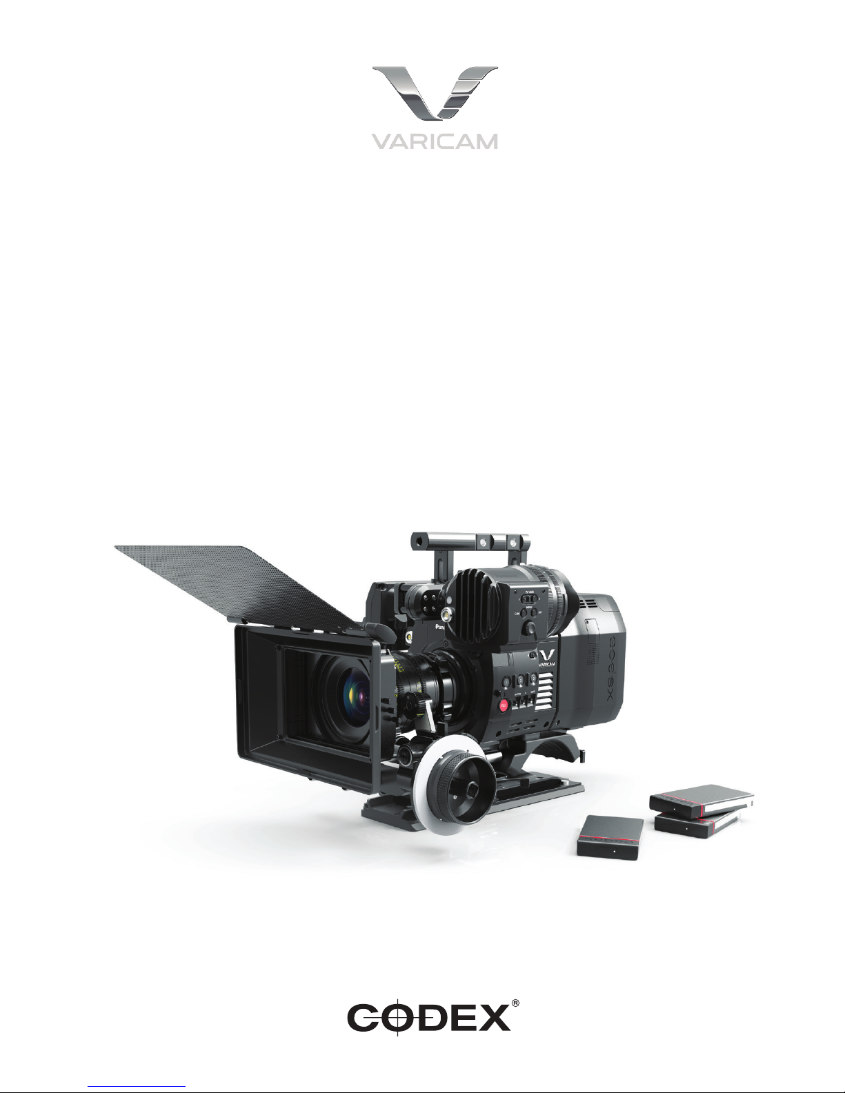
AU-VCXRAW2 Recorder - Getting Started Guide v2.0
1
Getting Started Guide
Version 2.0
AU-VCXRAW2 Recorder
for Panasonic VariCam Pure
Page 2

AU-VCXRAW2 Recorder - Getting Started Guide v2.0
2
Safety Warnings
Please observe any warnings and follow all instructions.
• Do not use this equipment near water and clean only with a dry cloth.
• Install in accordance with the manufacturer’s instructions.
• Do not install near any heat sources such as radiators, heat registers, stoves, or other equipment (including ampliers) that produce
heat.
• Do not expose to excessive vibration, or drop this product.
• Do not defeat the safety purpose of the polarised or grounding-type plug. A polarised plug has two blades with one wider than the
other. A grounding-type plug has two blades and a third grounding prong. The wide blade, or the third prong, is provided for your
safety.
• If the provided plug does not t into your outlet, consult an electrician for replacement of the obsolete outlet.
• Protect the power cord from being walked on or pinched, particularly at plug ends, convenience receptacles, and the point where they
exit from the equipment.
• Only use accessories specied by the manufacturer.
• Unplug this equipment during lightning storms or when not in operation for long periods of time.
• Refer all servicing to qualied service personnel. Servicing is required when the equipment has been damaged in any way, such as
power-supply cord or plug is damaged, liquid has been spilled or objects have fallen into the equipment, has been exposed to rain or
moisture, does not operate normally, or has been dropped.
• To reduce the risk of re or electric shock, do not expose equipment to rain or moisture.
• To avoid electrical shock, do not attempt to open this equipment. Refer servicing to qualied personnel only.
Caution! The surfaces of Capture Drive media can get hot during standard use.
Disclaimer
Codex products are continually developed to remain at the forefront of the industry, and as such the information in this guide is subject to
change without notice. Whilst Codex endeavour to ensure that all documentation provided is correct at the time of writing, this document
is not guaranteed to be error-free.
Codex does not assume responsibility for issues or losses due to misinterpretation of the information in this document, errors in this
document, or incorrect conguration or installation of the equipment described herein.
Please report any errors found in this document to [email protected]
Support and Servicing
For assistance with your AU-VCXRAW2 Recorder please contact [email protected]
User Guides are available from:
https://www.codex.online/support/user-guides
http://pro-av.panasonic.net/en/varicam/pure
http://pro-av.panasonic.net/en/varicam/35/dl.html
Page 3

AU-VCXRAW2 Recorder - Getting Started Guide v2.0
3
Contents
Codex AU-VCXRAW2 Recorder - Getting Started 4
Introduction ..................................................................................................................................................................... 4
Further documentation ................................................................................................................................................... 4
Attaching the Recorder to the Camera ........................................................................................................................... 4
Power requirement ......................................................................................................................................................... 5
Powering on.................................................................................................................................................................... 5
Loading and unloading a Capture Drive from the Recorder ........................................................................................... 6
Formatting a Capture Drive ............................................................................................................................................ 6
Camera settings 6
Menu conguration ......................................................................................................................................................... 7
Setting menu basic operation ......................................................................................................................................... 7
Setting menu initialization ............................................................................................................................................... 8
[SYSTEM SETTINGS] .................................................................................................................................................... 8
[CAMERA SETTINGS] ................................................................................................................................................13
[REC SETTINGS] ........................................................................................................................................................ 15
[AUDIO SETTINGS] .................................................................................................................................................... 17
[OUTPUT SETTINGS] ................................................................................................................................................. 19
[FILE] ........................................................................................................................................................................... 25
[PERIPHERAL] ............................................................................................................................................................ 25
Recording ..................................................................................................................................................................... 27
Playback ....................................................................................................................................................................... 27
Errors and warnings ..................................................................................................................................................... 27
Record times to Capture Drive 27
Using Codex Production Suite Software 28
Connecting a Capture Drive Dock 28
Loading and unloading a Capture Drive from the Dock................................................................................................ 28
Finder Preferences 29
Copying les from the Capture Drive 29
Page 4
AU-VCXRAW2 Recorder - Getting Started Guide v2.0
4
Codex AU-VCXRAW2 Recorder - Getting Started
Introduction
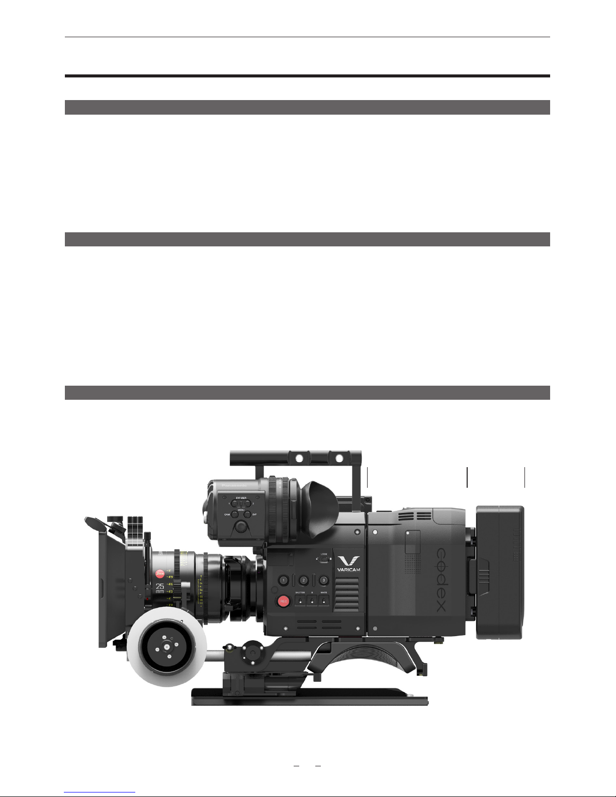
The Codex Recorder (AU-VCXRAW2) integrates with the Panasonic V35 Camera Module (AU-V35C1) to make the VariCam Pure
camera system. The system allows for uncompressed RAW capture at UHD or 4K at up to 120fps. The recorder attaches directly to the
camera, eliminating any need for cables and simplifying the use of the system.
After recording, the industry standard workow and support is provided via Codex Production Suite, Capture Drive Dock, or S-Series and
XL-Series hardware.
This guide is applicable to VariCam Pure rmware version 7.5.
Further documentation
The Codex Production Suite User Guide contains full details on the software features and use for common workows. Available from
https://codex.online/support/production-suite-user-guides
The VariCam 35 Manual is available from: http://pro-av.panasonic.net/en/varicam/35/dl.html
More information on the VariCam Pure is available from:
https://codex.online/camera-partners/panasonic
http://pro-av.panasonic.net/en/varicam/pure
Attaching the Recorder to the Camera
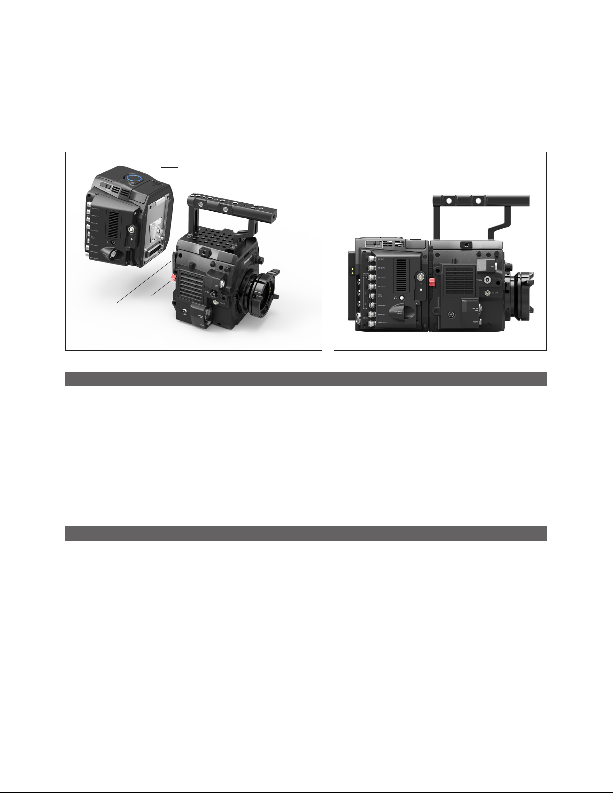
The AU-VCXRAW2 mounts to the rear of the AU-V35C1 as shown below:
AU-VCXRAW2 Battery
Page 5
AU-VCXRAW2 Recorder - Getting Started Guide v2.0
5
Follow these steps to mount the AU-VCXRAW2 to the rear of the AU-V35C1:
• Ensure the AU-VCXRAW2 is switched off and power is disconnected prior to installing the it to the AU-V35C1.
• Lift the red release catch and pull the black lever on the side of the AU-V35C1 to prepare the locking mechanism.
• Lower the AU-VCXRAW2 onto the rear of the AU-V35C1, engaging the top of the units rst. See below.
• Push the AU-VCXRAW2 and AU-V35C1 together to mate the connector interface.
• A positive clicking sound should be heard when the AU-VCXRAW2 and AU-V35C1 are successfully connected.
Black lever
Engage AU-VCXRAW2 with top rear
of AU-V35C1 using the hook locator
AU-VCXRAW2 mated with AU-V35C1
in locked position
Red
release
catch
Power requirement
The AU-VCXRAW2 has both a DC input and a mounting plate to attach batteries directly. It can be purchased with Anton Bauer or
V-Lock style battery plates (for sales enquiries contact [email protected]).
The AU-VCXRAW2 requires an input voltage of 11-34V. Power supplied to the AU-VCXRAW2 is fed through to the AU-V35C1. The
AU-VCXRAW2 and the AU-V35C1 has a total power requirement of 105W, with no devices attached to the accessory power outputs.
The accessory power outputs are regulated to 24V and support a combined current of 2A.
The AU-VCXRAW2 takes the DC input as the primary power source, and switches over to the battery when there is no DC input power
source. When a battery is directly attached this allows for switching of the DC input power source, which may be from a larger block
battery, without powering off the camera system.
Powering on
Connect a battery or DC power source to the AU-VCXRAW2. Press the power button on the AU-VCXRAW2 to start the system.
The light on the top of the AU-VCXRAW2 is red when the input voltage is below the minimum requirement.
Press the centre of the light on the top of the AU-VCXRAW2 to change the brightness between high, medium, low, and off.
Page 6
AU-VCXRAW2 Recorder - Getting Started Guide v2.0
6
Loading and unloading a Capture Drive from the Recorder
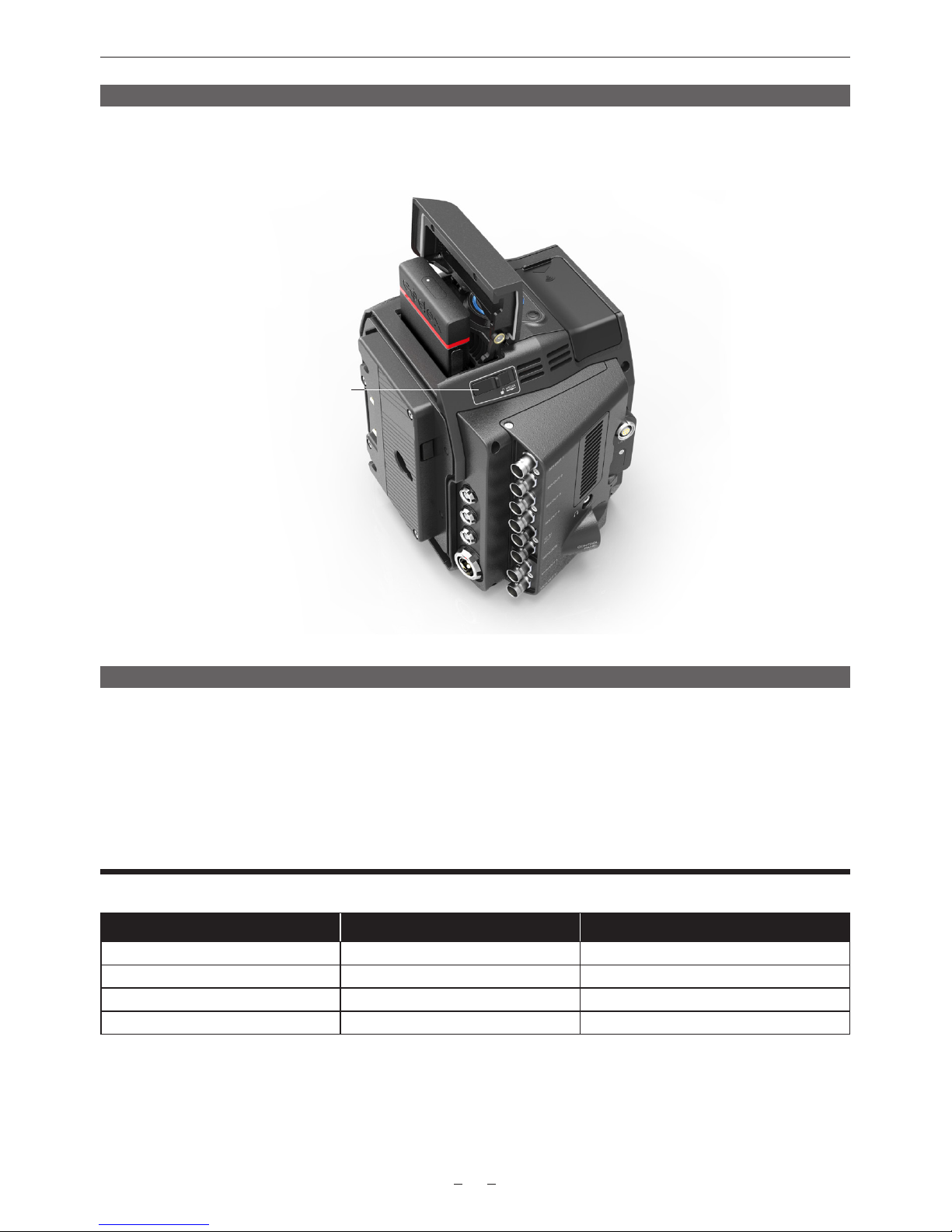
The door of the AU-VCXRAW2 is located on the top. Slide the release catch next to the door to open it. Insert the Capture Drive into the
AU-VCXRAW2. The base of the Capture Drive should be oriented towards the front of the AU-VCXRAW2. Push the Capture Drive from
the top to fully mate the connectors. Close the door and the Capture Drive will be loaded automatically.
Media access door with
inserted Capture Drive 1TB
Media release catch
Formatting a Capture Drive
To format the Capture Drive, navigate in the camera menu:
MENU->SYSTEM SETTINGS->CARDS/MEDIA->FORMAT MEDIA->V-RAW->YES
WARNING: ONLY DELETE MEDIA THAT HAS BEEN SECURELY BACKED UP. THERE IS NO UNDO FUNCTION AVAILABLE
AFTER FORMATTING.
Camera Settings
The VariCam Pure can record in the following formats:
Resolution Bit Depth Frame Rates
4096 x 2160 (4K) 12-bit 1-30fps (System Frequency up to 29.97p)
4096 x 2160 (4K) 10-bit 1-120fps
3840 x 2160 (UHD) 12-bit 1-30fps (System Frequency up to 29.97p)
3840 x 2160 (UHD) 10-bit 1-120fps
To set the recording format, from the HOME screen press ‘SYSTEM’ (bottom middle, below the display), then ‘V-RAW’ button (top
middle, above the display). If the desired format is not available, the list may be restricted by the current frame rate setting. To set the
frame rate, from the Home Screen press the ‘FPS’ button (top left, above the display). Press the VFR button to enable variable frame
rate settings. For highspeed mode, from the HOME screen press ‘SYSTEM’ and the ‘HIGH SPEED’ (bottom right, below the display).
Page 7
AU-VCXRAW2 Recorder - Getting Started Guide v2.0
7
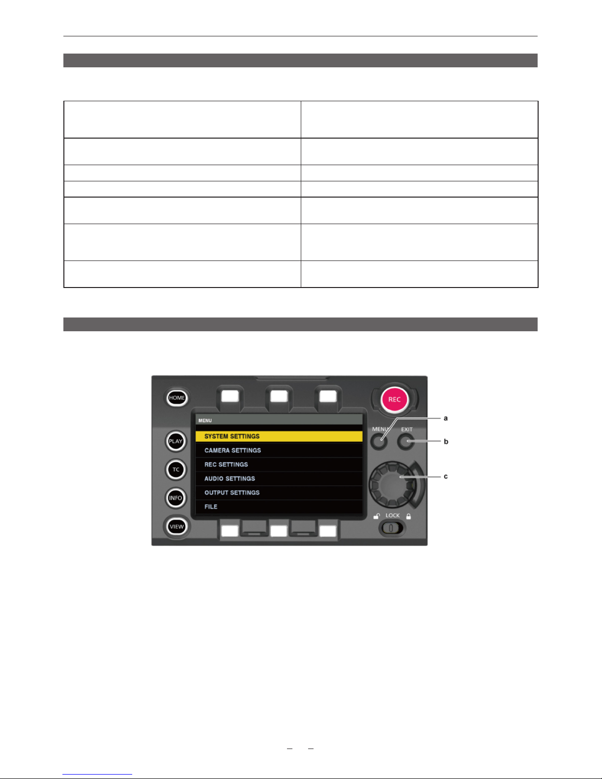
Menu conguration
The settings menu is congured as follows:
[SYSTEM SETTINGS] Sets the system in general.
Sets the system frequency, the number of lines, recording format,
and recording method.
[CAMERA SETTINGS] Sets the ne quality adjustment of camera videos and sets
camera operation. This item is also handled as a scene le.
[REC SETTINGS] The various setting items of the recording function of the camera.
[AUDIO SETTINGS] Various setting items for audio recording.
[OUTPUT SETTINGS] Sets the content of displaying output video from the video output
terminal.
[FILE] Performs le-related operations such as reading/writing menu
settings data from/to an SD memory card, and handling lens
les. This item will be available in future version upgrade.
[PERIPHERAL] Applies settings related to functions used in conjunction with
peripheral devices, such as network and GPS devices.
Setting menu basic operation
You can change camera settings using the setting menu according to the shooting scene and recording details.
Set data are written and saved in the internal memory of the camera.
a) <MENU> button
b) <EXIT> button
c) Jog dial button
1. Press the <MENU> button when not recording.
- The [MENU] screen is displayed on the control panel.
2. Turn the jog dial button to place the cursor on the desired menu item.
- Turn the jog dial button to move the cursor vertically.
3. Press the jog dial button.
- The next level of screen is displayed.
- If there is another level, press the jog dial button again to display it.
- The current setting value of the item selected on the right is displayed.
4. Turn the jog dial button to place the cursor on the desired item.
5. Press the jog dial button.
- The item is in the setting status.
- If there are two items, the setting value selection frame may be displayed on the right.
Page 8
AU-VCXRAW2 Recorder - Getting Started Guide v2.0
8
6. Turn the jog dial button to place the cursor on the desired item.
7. Press the jog dial button.
- Setting is completed.
8. Press the <EXIT> button to close the menu.
Setting menu initialization
Select [LOAD FACTORY DATA] from [MENU] → [SYSTEM SETTINGS] → [INITIALIZE].
[MENU] setting values are reset to factory settings.
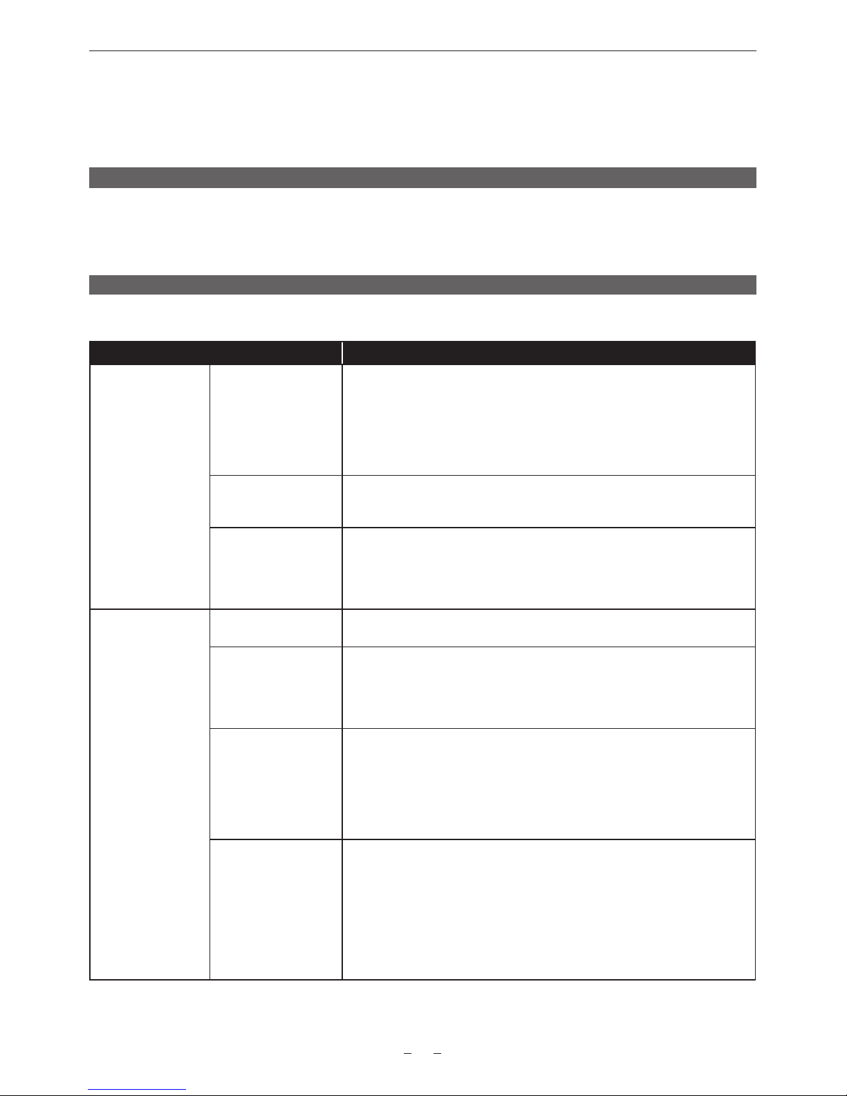
[SYSTEM SETTINGS]
Sets the system in general.
Item Description of settings
[SYSTEM MODE] [FREQUENCY] Sets the system frequency.
If the setting of this item is changed, the device must be restarted. If a restart is
required, a conrmation dialog will be shown.
The camera’s system operation are determined by four settings: [FREQUENCY],
[V-RAW], and [HIGH SPEED]. Check the three settings.
[23.98p], [24.00p], [25.00p], [29.97p], [50.00p], [59.94p],
Factory setting: [23.98p]
[V-RAW] Sets the V-RAW format.
[4K/12bit], [4K/10bit], [UHD/12bit], [UHD/10bit]
Factory setting: [4K/12bit]
[HIGH SPEED] Sets the high speed mode.
[ON (**-**fps)], [OFF (1-**fps)]
When [HIGH SPEED] is set to [ON (**-**fps)], [CAMERA SETTINGS] → [FPS] →
[VFR SW] is xed to [ON].
Factory setting: [OFF (1-60fps)]
[COLOR SETTING] [MAIN & VRAW] It is xed to [V-Log] when connected to the AU-VCXRAW2.
Factory setting: [V-Log]
[GRADING] Sets whether to apply the grading process.
[Internal]: Sets grading with the control panel.
[OFF]: Disables the grading process.
[External App]: Sets the grading using an external application.
Factory setting: [OFF]
[3D LUT] Sets the grading process method when [GRADING] is set to [Internal] or
[External App].
When [GRADING] is set to [Internal] or [External App]
[OFF]/[V-709]/[LOADED FILE]/[FILE SEL]/[SAVE AS(SD CARD)]
When [GRADING] is set to [OFF]
[OFF]
Factory setting: [OFF]
[PLAYBACK GRADING] Sets the grading method during the playback.
[ON]: Applies grading process to the playback video based on the grading
information of the recording.
[OFF]: Performs grading process to the playback video based on the setting in
[SYSTEM SETTINGS]
→ [COLOR SETTING] → [MON 1]/[MON 2]/[VF]/[VF SDI]. The grading process is
applied only to video recording V-Log.
The grading process is not performed to the video from the SDI output terminal.
Factory setting: [OFF]
Page 9

AU-VCXRAW2 Recorder - Getting Started Guide v2.0
9
Item Description of settings
[CDL] Sets the grading process method when [GRADING] is set to [Internal] or
[External App].
When [GRADING] is set to [Internal]/[External App]:
[ON]/[OFF]/[SAVE AS(SD CARD)]
When [GRADING] is set to [OFF]: [OFF]
Factory setting: [OFF]
[MON 1] Sets the output image from the <MON OUT1> terminal.
Selectable items vary depending on the [GRADING] setting.
When [GRADING] is set to [Internal]/[External App]:
[V-Log]/[GRADING]
When [GRADING] is set to [OFF]:
[V-Log]/[V-709]
Factory setting: [V-Log]
[MON 2] Sets the output image from the <MON OUT2> terminal.
Selectable items vary depending on the [GRADING] setting.
When [GRADING] is set to [Internal]/[External App]:
[V-Log]/[GRADING]
When [MAIN] is set to [V-Log] and [GRADING] is set to [OFF]:
[V-Log]/[V-709]
Factory setting: [V-Log]
[VF] Sets the output image from the <VF> terminal and the <VF SDI> terminal.
Selectable items vary depending on the [GRADING] setting.
When [GRADING] is set to [Internal]/[External App]:
[V-Log]/[GRADING]/[V-709]/[LCC]
When [GRADING] is set to [OFF]:
[V-Log]/[V-709]/[LCC]
Factory setting: [V-Log]
[VF SDI] Sets the output image from the <VF SDI> terminal.
[Same As VF]/[V-Log]
Factory setting: [Same As VF]
[ANAMORPHIC
DESQUEEZE]
[MON OUT] Sets if the monitor output image is to be de-squeezed.
[ON], [OFF]
Factory setting: [OFF]
[VF & VF SDI] Sets if the output image from the <VF> terminal and the <VF SDI> terminal is to
be de-squeezed.
[ON], [OFF]
Factory setting: [OFF]
[DESQUEEZE RATIO] Sets the de-squeeze ratio.
[1.3x]: De-squeeze 1.3 times in horizontal direction.
[1.3xmag]: It will be in aspect ratio of 2.39:1 for mastering generated from the
image de-squeezed 1.3 times in horizontal direction.
[2.0x]: De-squeeze 2.0 times in horizontal direction.
[2.0xmag]: It will be in aspect ratio of 2.39:1 for mastering generated from the
image de-squeezed 2.0 times in horizontal direction.
Factory setting: [1.3x]
Page 10

AU-VCXRAW2 Recorder - Getting Started Guide v2.0
10
Item Description of settings
[IMAGE INVERT] [MON OUT] Sets if the monitor output image is to be inverted.
[ON], [OFF]
Factory setting: [OFF]
[VF & VF SDI] Sets if the output image from the <VF> terminal and the <VF SDI> terminal is to
be inverted.
[ON], [OFF]
Factory setting: [OFF]
[INVERT SELECT] Sets the type of inversion.
[VERTICAL]: Invert vertically
[HORIZONTAL]: Invert horizontally
[180° ROTATE]: Invert vertically and horizontally
Factory setting: [HORIZONTAL]
[USER SWITCHES] [USER1] - [USER4] Sets the function to be assigned to the USER <1> to USER <4> buttons.
[INHIBIT], [SIX USER BUTTONS], [AWB], [ABB], [Y GET], [EXPAND], [IN
COLOR/SQ./MONO], [WFM], [BARS], [FRAME LINE], [FALSE COLOR], [VF
COLOR], [MON1 COLOR], [MON2 COLOR], [VF DESQUEEZE], [VF IMAGE
INVERT], [SHOT MARK], [REC SW], [AUDIO MON VOL], [AUDIO IN VOL]
Factory setting: [INHIBIT]
[USER5] - [USER10] Sets the function to be assigned to the control panel operation button. The control
panel operation button functions as a USER button.
Assign [SIX USER BUTTONS] to USER buttons <5> to <10>.
[INHIBIT], [EXPAND], [IN COLOR/SQ./MONO], [FRAME LINE], [FALSE COLOR],
[VF COLOR], [MON1 COLOR], [MON2 COLOR]
Factory setting: [INHIBIT]
[CARDS/MEDIA] [FORMAT MEDIA] Formats the Capture Drive media in the AU-VCXRAW2.
[V-RAW]
Data deleted as a result of formatting cannot be restored. Always check the data
before formatting.
[MEDIA END ALARM] Sets whether to generate an alarm sound when there is no remaining free space
in the Capture Drive.
[ON], [OFF]
Factory setting: [ON]
[POWER
MANAGEMENT]
ONBOARD BATTERY
SETTINGS
(Display Only)
[ - FULL VOLT] Sets the voltage in the remaining charge level full display when the battery
remaining charge level is detected from the voltage level.
[13.0V] - [17.0V] (0.1 V step)
Factory setting: [15.5V]
[ - NEAR END VOLT] Sets the remaining charge level near end voltage when the battery remaining
charge level is detected from the voltage level.
[11.0V] - [15.0V] (0.1 V step)
Factory setting: [13.2V]
[ - END VOLT] Sets the remaining charge level end voltage when the battery remaining charge
level is detected from the voltage level.
[11.0V] - [15.0V] (0.1 V step)
Factory setting: [12.5V]
[ - NEAR END INFO] Sets the percentage value of the remaining charge level near end when
remaining charge level information is acquired from the battery.
[4%], [5%], [6%], [7%], [8%], [9%], [10%], [12%], [14%], [16%], [18%], [20%]
Factory setting: [5%]
Page 11

AU-VCXRAW2 Recorder - Getting Started Guide v2.0
11
Item Description of settings
[ - END INFO] Sets the percentage value of the remaining charge level end when remaining
charge level information is acquired from the battery.
[1%] - [10%] (1% step)
Factory setting: [1%]
[DC IN BATTERY
SETTINGS]
(Display Only)
[DC IN SOURCE] Sets the type of the external power supply input into the <DC IN> terminal.
[DC POWER SUPPLY]: Selected when connecting an AC adaptor. In this case,
the remaining battery charge level is not displayed.
[BATTERY]: Selected when connecting a battery to the <DC IN> terminal.
Remaining charge level is detected from the voltage level.
Factory setting: [DC POWER SUPPLY]
[- FULL VOLT] Sets the voltage to be displayed in the remaining charge level full display when
an external battery is input from the <DC IN> terminal.
[13.0V] - [34.0V] (0.1 V step)
Factory setting: [31V]
[- NEAR END VOLT] Sets the remaining charge level near end voltage when an external battery is
input from the <DC IN> terminal.
[11.0V] - [30.0V] (0.1 V step)
Factory setting: [21.0V]
[- END VOLT] Sets the remaining charge level end voltage when an external battery is input
from the <DC IN> terminal.
[11.0V] - [30.0V] (0.1 V step)
Factory setting: [20.0V]
[END ALARM] Sets whether to sound an alarm at battery remaining charge level end.
[ON], [OFF]
Factory setting: [ON]
[FAN] [FAN SPEED] Select the rotation speed of the fan.
[REC AUTO]: The rotation speed is lowered simultaneously with start of
recording. However, the fan will rotate in maximum speed when it reaches the
specied temperature.
[ALWAYS FULL]: The fan will always rotate at the maximum speed.
Factory setting: [REC AUTO]
[GENLOCK] [GENLOCK MODE] Switches the synchronization signal of the camera signal.
[INT]: Synchronizes to the internal standard signal.
[EXT]: Synchronizes to the entered external standard signal.
Factory setting: [INT]
[H PHASE COARSE] Roughly adjusts to match horizontal synchronization phase when building a
system.
[−100]…[100]
Factory setting: [0]
[H PHASE FINE] Minutely adjusts to match horizontal synchronization phase when building a
system.
[−100]…[100]
Factory setting: [0]
Page 12
AU-VCXRAW2 Recorder - Getting Started Guide v2.0
12
Item Description of settings
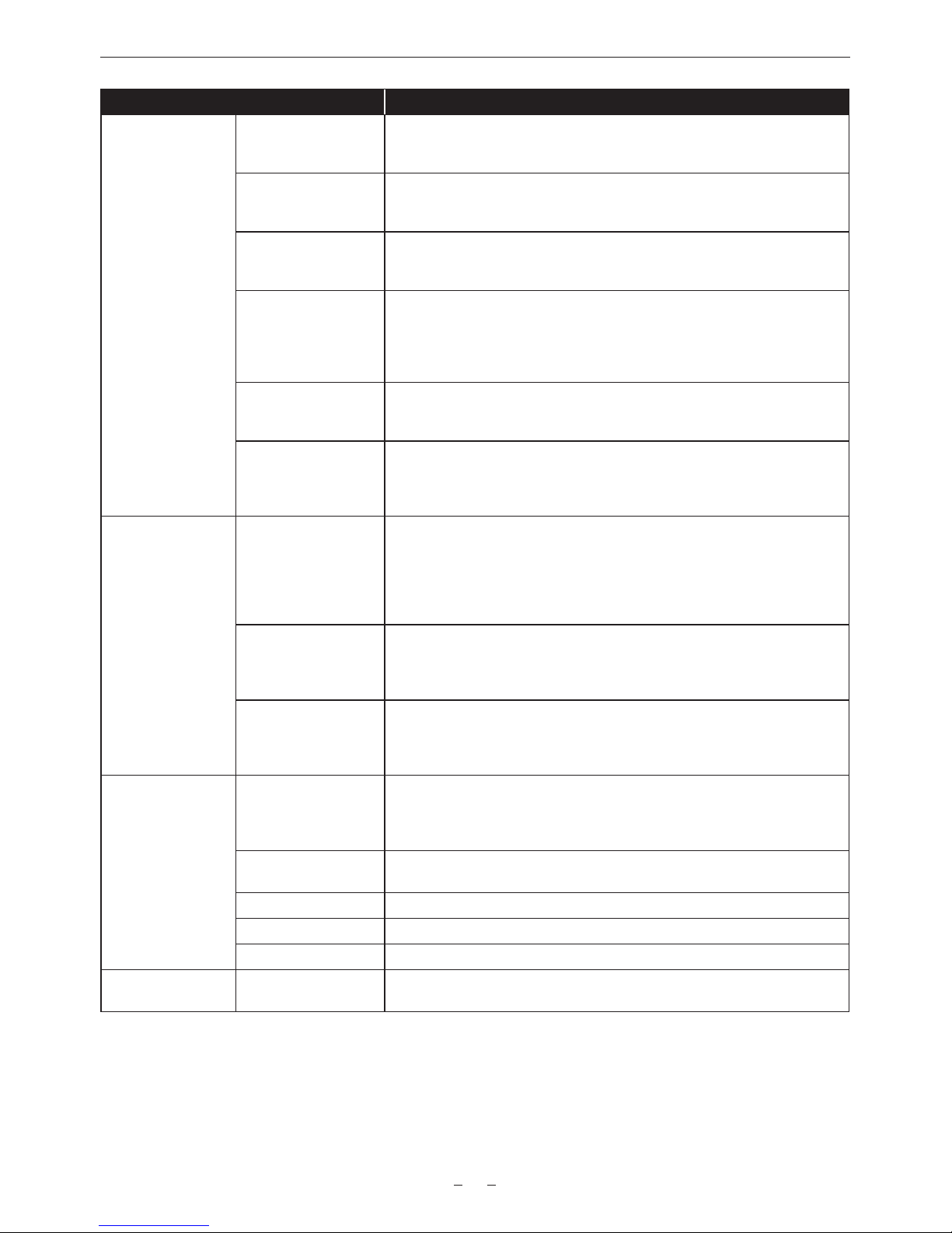
[CONTROL
DISPLAY]
[BRIGHTNESS] Adjusts the brightness of the control panel.
[−15]…[15]
Factory setting: [0]
[COLOR LEVEL] Adjusts the color levels of the control panel.
[−15]…[15]
Factory setting: [0]
[CONTRAST] Adjusts the contrast of the control panel.
[−30]…[30]
Factory setting: [0]
[BACK LIGHT] Sets the brightness of the control panel backlight.
[−1]: Darkens the display more than normal.
[0]: Normal brightness.
[1]: Brightens the display more than normal.
Factory setting: [0]
[BUTTON LED] Illuminates each button of the control panel and camera module.
[ON], [OFF]
Factory setting: [ON]
[STATUS] Press the <VIEW> button to set whether to show the status display when a
camera video is displayed on the control panel.
[ON], [OFF]
Factory setting: [ON]
[CLOCK] [CLOCK SETTING] Sets the built-in calendar (year/month/day) and time.
[YEAR]: [2014] - [2037]
[MONTH]: [JAN]…[DEC] ([1]…[12])
[DAY]: [1] - [31] ([28], [29], [30])
[HOUR]: [0] - [23]
[MINUTE]: [0] - [59]
[TIME ZONE] Set the time zone. After setting the time, when changing the time zone setting,
the displayed and registered times switch to the time with the time difference.
[−12:00] - [+13:00]
(30-minute interval, without [+12:30] and with [+12:45])
[DATE FORMAT] Sets the display order of year/month/day.
This is also applied to the recording date displayed in the clip properties.
[Y-M-D]/[M-D-Y]/[D-M-Y]
Factory setting: [Y-M-D]
[INFORMATION] [VERSION] Displays the information of the camera.
[VERSION]: Displays the version.
[MODEL NAME]: Displays the product name.
[SERIAL NO.]: Displays the serial number.
[UPDATE] Performs an update of the camera rmware. (Enabled only when there is a
dedicated update le on the SD memory card.)
[USB] Switches the camera to mode for USB device function.
[TRACE LOG] Reads the camera’s execution log from an SD memory card.
[SENSOR TEMP] Displays the ambient temperature detected by the camera module’s sensor.
[INITIALIZE] [LOAD FACTORY
DATA ]
Returns the menu values to their factory settings.
[YES], [NO]
Page 13
AU-VCXRAW2 Recorder - Getting Started Guide v2.0
13
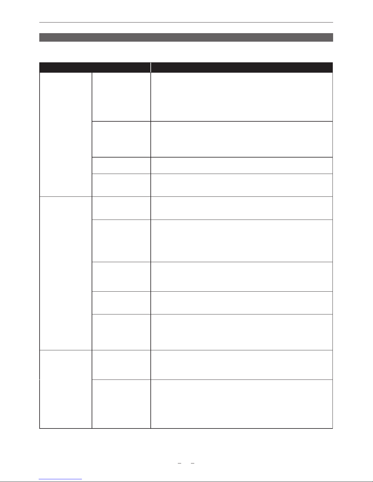
[CAMERA SETTINGS]
Sets the adjustment of camera recordings and operation.
Item Description of settings
[FPS] [VFR SW] Enables/disables variable frame rate.
[ON]: Enables the variable frame rate function. The desired frame rate can be set
using [PRESET VALUE]/[VARIABLE VALUE]. Audio cannot be recorded.
[OFF]: Disables the variable frame rate function. [VFR SW] is xed to [ON] when
[SYSTEM SETTINGS] → [SYSTEM MODE] → [HIGH SPEED] is set to [ON
(**-**fps)].
Factory setting: [OFF]
[FPS MODE] Selects the frame rate setting method.
[PRESET]: Selects the frame rate from preset frame rates (maximum of 12).
Registration is done from the control panel.
[VARIABLE]: Selects the frame rate from all available frame rates.
Factory setting: [PRESET]
[PRESET VALUE] Selects a value from a maximum of 12 values set from the control panel.
Factory setting: [24fps]
[VARIABLE VALUE] Selects the frame rate from all available frame rates. Selectable values vary
depending on [SYSTEM MODE] settings.
Factory setting: [24fps]
[WHITE] [AWB] Executes automatic white balancing.
[EXECUTE], [CANCEL]
Factory setting: [CANCEL]
[MODE] Selects the white balance mode.
[PRESET]: Selects the color temperature from preset color temperatures.
Registration is done from the control panel.
[TEMP SHIFT]: Selects the color temperature from all congurable color
temperatures.
Factory setting: [PRESET]
[PRESET VALUE] Selects a value from a maximum of 12 values set from the control panel.
Preset values that can be selected in the factory setting are [3200K+0GMg],
[4300K+0GMg], [5600(5500)K+0GMg], and [6300K+0GMg].
Factory setting: [3200K+0GMg]
[TEMP SHIFT] Selects the color temperature from all congurable color temperatures.
[2300K]…[15000K]
Factory setting: [3200K]
[GMg] Adjusts the balance between green and magenta.
+: Adjusts toward green.
−: Adjusts toward magenta.
[−10]…[10]
Factory setting: [0]
[BLACK] [ABB] Executes automatic black balancing. When executing automatic black balancing,
put the cap on the lens to keep any light from entering the image sensor.
[EXECUTE], [CANCEL]
Factory setting: [CANCEL]
[INITIAL ABB] Executes the initialization of the sensor at the same time the automatic black
balance is executed.
This can be selected only when [HIGH SPEED] is set to [ON].
Keep the light away from the image sensor by placing a cap on the lens, etc.,
when executing the automatic black balance.
[EXECUTE], [CANCEL]
Factory setting: [CANCEL]
Page 14

AU-VCXRAW2 Recorder - Getting Started Guide v2.0
14
Item Description of settings
[NR] [ISO800] Switches the noise reduction effect in the range of ISO200 to ISO4000.
[ON], [OFF]
The range will be ISO200 to ISO2000 when [HIGH SPEED] is set to [ON].
The range will be 0 dB to 15 dB when [MODE] in [EI] is set to [dB].
Factory setting: [OFF]
[ISO5000] Switches the noise reduction effect in the range of ISO5000 to ISO12800.
[ON], [OFF]
The range will be ISO2500 to ISO6400 when [HIGH SPEED] is set to [ON].
The range will be 18 dB to 24 dB when [MODE] in [EI] is set to [dB].
Factory setting: [OFF]
[EI] [MODE] Switches the EXPOSURE INDEX control unit.
[ISO], [dB]
Factory setting: [ISO]
[ISO SELECT] Selects the operation of ISO.
[NATIVE ONLY], [800BASE], [5000BASE]
Factory setting: [NATIVE ONLY]
[NATIVE ISO] Sets the value when [NATIVE ONLY] is selected.
[800], [5000]
The value will be [400] and [2500] when [HIGH SPEED] is set to [ON].
Factory setting: [800]
[800BASE ISO] Sets the value when [800BASE] is selected.
[200], [250], [320], [400], [500], [640], [800], [1000], [1250], [1600], [2000], [2500],
[3200], [4000], [5000], [6400], [8000], [10000], [12800]
It will be [200], [250], [320], [400], [500], [640], [800], [1000], [1250], [1600],
[2000], [2500], [3200], [4000], [5000], and [6400] when the setting of [HIGH
SPEED] is [ON].
Factory setting: [800]
[5000BASE ISO] Sets the value when [5000BASE] is selected.
[1250], [1600], [2000], [2500], [3200], [4000], [5000], [6400], [8000], [10000],
[12800]
It will be [1250], [1600], [2000], [2500], [3200], [4000], [5000], and [6400] when
[HIGH SPEED] is set to [ON].
Factory setting: [5000]
[SETTING(GAIN)] Sets the value when [dB] is selected.
[0dB], [3dB], [6dB], [9dB], [12dB], [15dB], [18dB], [21dB], [24dB]
Factory setting: [0dB]
[SHUTTER] [SW] Enables/disables the shutter function.
[ON], [OFF]
Factory setting: [ON]
[DISPLAY MODE] Sets the shutter display unit.
[sec]: Displays in time.
[deg]: Displays at shutter open angle.
Factory setting: [deg]
[MODE] Switches the shutter control mode.
[PRESET]: Selects the mode from 12 modes inside the memory.
[SYNCHRO]: Selects the mode from the operable range.
Factory setting: [PRESET]
[SYNCHRO deg] Sets the value of angle control ([deg]).
[1.0]…[358.0]
Factory setting: [180.0]
[SYNCHRO sec] Sets the value of time control ([sec]). The lowest value changes depending on the
frame rate ([FPS]) value.
[1/60] - [1/250]
Factory setting: [1/48]
Page 15
AU-VCXRAW2 Recorder - Getting Started Guide v2.0
15
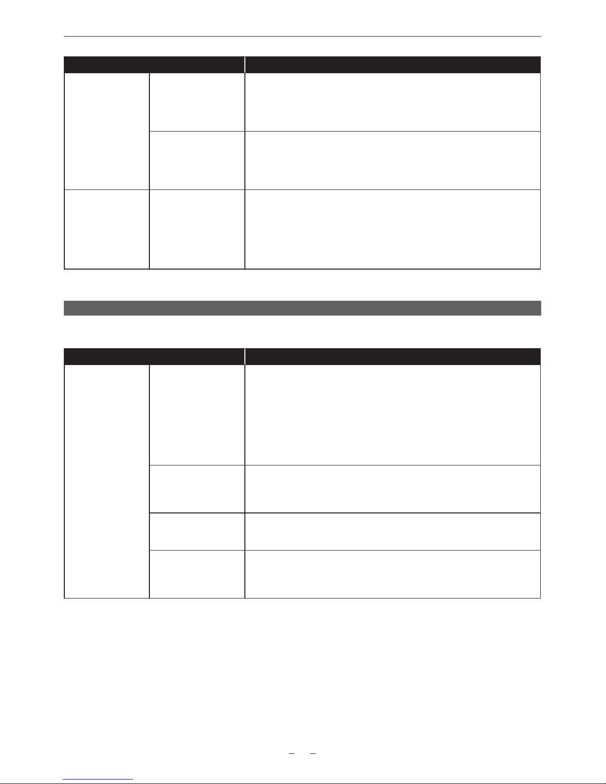
Item Description of settings
[PRESET VALUE deg] Selects the angle control ([deg]) value from the maximum of 12 values set in the
control panel.
Preset values that can be selected in the factory setting are [11.5], [22.5], [45.0],
[90.0], [120.0], [144.0], [172.8], [180.0], [270.0], and [358.0].
Factory setting: [180.0]
[PRESET VALUE sec] Selects the time control ([sec]) value from the maximum of 12 values set in the
control panel.
Preset values that can be selected in the factory setting are [1/60], [1/100],
[1/120], [1/250], [1/500], [1/1000], and [1/2000].
Factory setting: [1/60]
[LENS SETTING] [LENS CONNECT
TYPE]
Sets the type of lens to be connected.
[TYPE A]: Lens controlled with LDS (Lens Data System). (ULTRA PRIME lens
not supported)
[TYPE B]: Lens controlled with 12-pin connector
[TYPE C]: Lens controlled with cooke/i communication
[OFF]: Other lenses
Factory setting: [OFF]
[REC SETTINGS]
The various setting items of the recording function of the camera.
Item Description of settings
[REC FUNCTION] [REC MODE] Selects the special recording function.
[NORMAL]: Normal recording
[INTERVAL]: Interval recording (function to perform intermittent recording in
constant interval)
[ONE SHOT]: One-shot recording (function to perform recording of specied
duration every time the REC button is pressed)
The setting is xed to [NORMAL] when [SYSTEM SETTINGS] → [MON OUT
INDICATOR] → [VFR] is set to [ON].
Factory setting: [NORMAL]
[REC TIME] Sets the recording duration of single one-shot recording.
[00s01f]…[59s23f]
The maximum value of the frame digit differs depending on the system frequency.
Factory setting: [00s01f]
[INTERVAL TIME] Sets the intermittent recording frequency of single interval recording.
[0h00min00s02f]…[1h00min00s00f]
Factory setting: [0h05min00s00f]
[START DELAY] Sets the delay time to start recording for the interval recording and the one-shot
recording.
[0s]…[10s]
Factory setting: [0s]
Page 16

AU-VCXRAW2 Recorder - Getting Started Guide v2.0
16
Item Description of settings
[TC] [SET TC] Sets the default value of the time code to record.
Hour: [00] - [23]
Minute: [00] - [59]
Second: [00] - [59]
Frame: [00]…[23] (for [24p], [23.98p]), [00]…[23] (for [50i], [50p], [25p]), [00]…
[29] (for [59.94i], [59.94p], [29.97p])
Factory setting: [00] (various items)
[SET UB] Sets user bits. Enabled only when [USER] is selected in [UB MODE].
This can be set by each digit from [00] to [FF].
Factory setting: [00]
[TC/UB/Dur.] Switches the time code display to the user bits and duration counter display.
[TC], [UB], [Dur.]
Factory setting: [TC]
[FREE/REC RUN] Sets the operation mode to advance the built-in time code generator. It will be
xed to [REC RUN] when [VFR] is set to [ON].
[FREE RUN]: Advances regardless of the operation mode.
[REC RUN]: Advances when recording is in process.
Factory setting: [FREE RUN]
[DF/NDF] Sets count method for the built-in time code generator of the camera.
[DF]: Uses the drop frame mode.
[NDF]: Uses the non-drop frame mode.
Factory setting: [NDF]
Enabled only when [59.94i], [59.94p], or [29.97p] is selected in [MENU] →
[SYSTEM SETTINGS] → [SYSTEM MODE] → [FREQUENCY].
[UB MODE] Selects the user bits mode.
[FRAME RATE]: Selects camera imaging information (such as frame rate).
[USER]: Selects the user bits value that has been set.
[EXT INPUT]: Records the user bits values currently input to the <TC IN/OUT>
terminal.
[TIME]: Selects the local time. (hh, mm, ss)
[DATE]: Selects the local date and time. (YY, MM, DD, hh)
[USER CLIP NAME (TYPE3)]: CAM INDEX (A-Z) in ASCII character code will
go into MSB. Also, the REEL number in ASCII character code will go into LSB 3
digits.
Example: A123=0x41 0x31 0x32 0x33
0XFFFF is recorded if [USER CLIP NAME] is set to anything other than [TYPE3].
Factory setting: [FRAME RATE]
[TC IN/OUT SEL] Sets the input/output of the <TC IN/OUT> terminal.
[TC IN], [TC OUT]
Factory setting: [TC IN]
[TC OUT] Selects the time code output to the <TC IN/OUT> terminal.
[TCG], [TCG/TCR]
Factory setting: [TCG]
[TC OUT REF] Sets the output delay of the time code output from the <TC IN/OUT> terminal.
[RECORDING], [SDI OUT]
Factory setting: [RECORDING]
[REC METADATA] [CAM INDEX] Sets CAM INDEX used in [TYPE3] of [USER CLIP NAME].
[A]…[Z]
Factory setting: [A]
[NEXT REEL COUNT] Sets REEL used in [TYPE3] of [USER CLIP NAME]. The REEL number for the
card that the REEL number is already assigned would not change.
[001]…[999]
Factory setting: [001]
[PROPERTY] Checks loaded metadata. This cannot be modied.
Page 17
AU-VCXRAW2 Recorder - Getting Started Guide v2.0
17
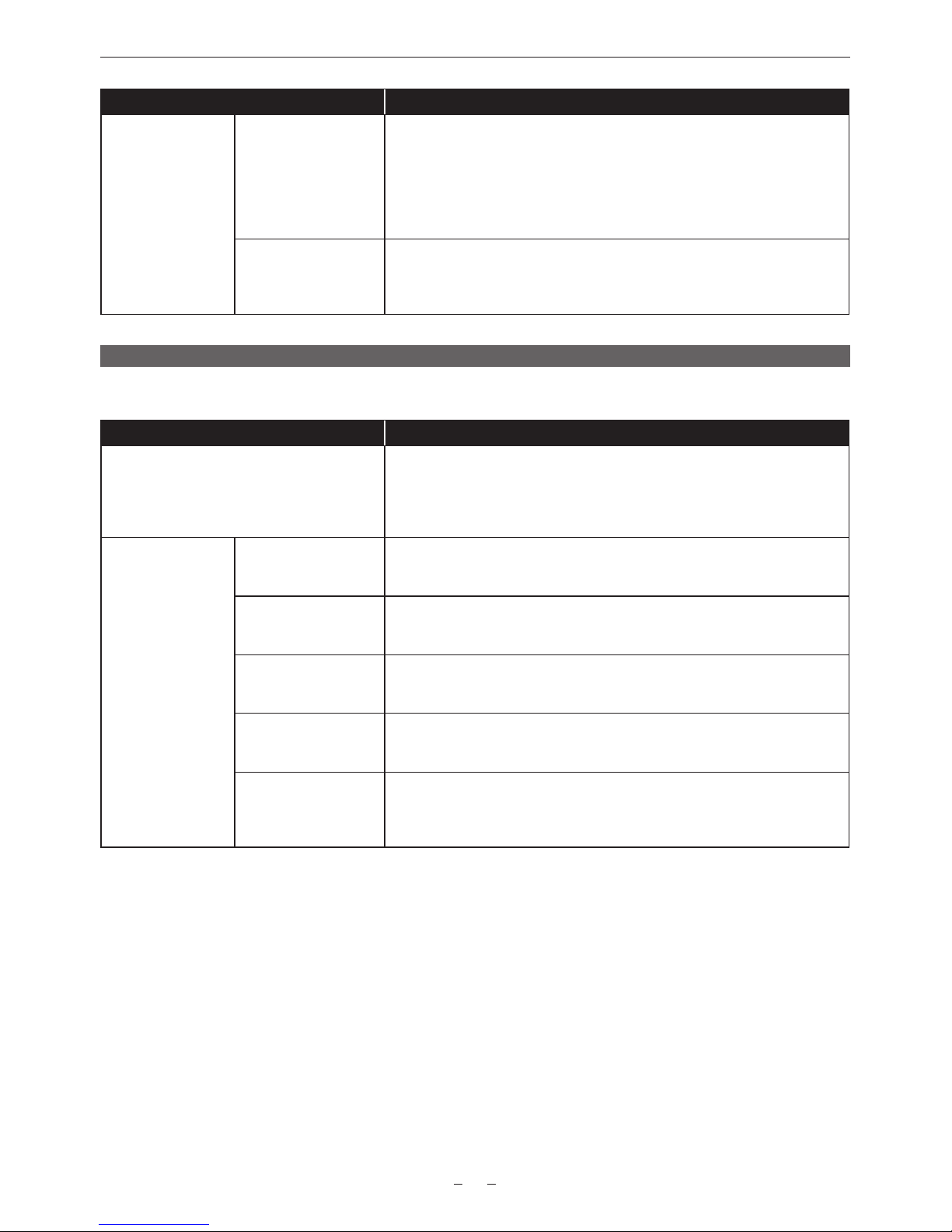
Item Description of settings
[REC BEEP SOUND] [MODE] Sets if the beep sound is output at the time when the recording is started or
stopped.
[OFF]: It is not output for both starting and stopping of the recording.
[START]: It is output at the start of recording.
[STOP]: It is output at the stop of recording.
[START & STOP]: It is output for both starting and stopping of the recording.
Factory setting: [OFF]
[VOLUME] Sets the volume of the beep sound that is output at the time when the recording
is started or stopped.
[LOUD], [MEDIUM], [SMALL]
Factory setting: [MEDIUM]
[AUDIO SETTINGS]
Various setting items for audio recording.
Item Description of settings
[AUDIO RECORD] Sets whether to record the audio.
The audio data itself is not recorded when set to [OFF]. (Audio data will not
appear in the timeline of editing software)
[ON], [OFF]
Factory setting: [ON]
[AUDIO INPUT] [FRONT MIC POWER] Enables/disables the front microphone phantom power.
[ON], [OFF]
Factory setting: [ON]
[FRONT MIC LEVEL] Sets the front microphone input level.
[−40dB], [−50dB]
Factory setting: [−40dB]
[FRONT1 MIC
LOWCUT]
Enables/disables the low-cut lter of front microphone 1.
[ON], [OFF]
Factory setting: [OFF]
[FRONT2 MIC
LOWCUT]
Enables/disables the low-cut lter of front microphone 2.
[ON], [OFF]
Factory setting: [OFF]
[TEST TONE] Sets whether to output a test signal when the video is made to a color bar.
[ON]: Outputs a test tone.
[OFF]: Does not output a test tone.
Factory setting: [ON]
Page 18
AU-VCXRAW2 Recorder - Getting Started Guide v2.0
18
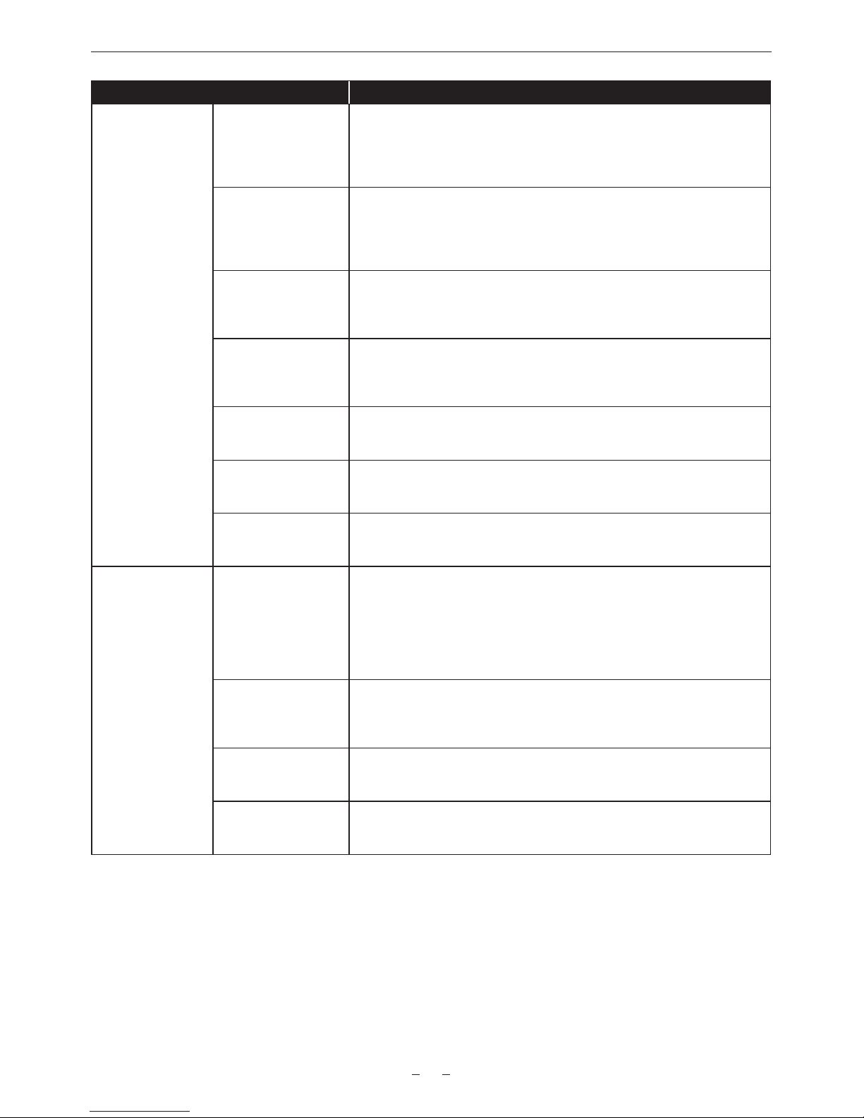
Item Description of settings
[AUDIO LEVEL] [FRONT1 LEVEL] Sets the level adjustment method of the front microphone 1 to manual or
automatic.
[AUTO]: Adjust automatically.
[MANUAL]: Enables manual adjustment.
Factory setting: [AUTO]
[FRONT2 LEVEL] Sets the level adjustment method of the front microphone 2 to manual or
automatic.
[AUTO]: Adjust automatically.
[MANUAL]: Enables manual adjustment.
Factory setting: [AUTO]
[FRONT1 VOL] Performs adjustments in this item when the level adjustment method of the front
microphone 1 is set to [MANUAL].
[0]…[100]
Factory setting: [70]
[FRONT2 VOL] Performs adjustments in this item when the level adjustment method of the front
microphone 2 is set to [MANUAL].
[0]…[100]
Factory setting: [70]
[FRONT1 LIMITER] Enables/disables the limiter of front microphone 1.
[ON], [OFF]
Factory setting: [OFF]
[FRONT2 LIMITER] Enables/disables the limiter of front microphone 2.
[ON], [OFF]
Factory setting: [OFF]
[HEADROOM] Sets the headroom (standard level).
[18dB], [20dB]
Factory setting: [20dB]
[AUDIO OUTPUT] [MONITOR SEL2] Sets the audio format (mono, stereo, mix) to be output from the <PHONES>
terminal.
When [MONITOR SEL1] is set to [CH1/2]:
[MONO CH1], [MONO CH2], [STEREO CH1/2], [MIX CH1/2]
When [MONITOR SEL1] is set to [CH3/4]:
[MONO CH3], [MONO CH4], [STEREO CH3/4], [MIX CH3/4]
Factory setting: [STEREO CH1/2] or [STEREO CH3/4]
[MONITOR DELAY] Sets whether to delay the audio from the <PHONES> terminal to match the
monitor output.
[ON], [OFF]
Factory setting: [OFF]
[MONITOR VOL] Adjusts the level of audio to be output from the <PHONES> terminal.
[0]…[100]
Factory setting: [70]
[ALARM] Sets the volume of the warning sound to be output from the <PHONES> terminal.
[LOUD], [MEDIUM], [SMALL], [OFF]
Factory setting: [MEDIUM]
Page 19

AU-VCXRAW2 Recorder - Getting Started Guide v2.0
19
[OUTPUT SETTINGS]
Sets the display content of the output video from the viewnder and <VF SDI> terminal.
Item Description of settings
[SDI OUT] [4K OUT TYPE] Sets the 4K signal format to be output from terminals <SDI OUT1> to <SDI
OUT4>.
[SQUARE], [2 SAMPLE INT]
Factory setting: [SQUARE]
[3G-SDI OUT] Sets the 3G SDI signal format to be output from terminals <SDI OUT1> to <SDI
OUT4>.
[LEVEL-A]: Selects the LEVEL-A method.
[LEVEL-B]: Selects the LEVEL-B DL method.
Factory setting: [LEVEL-B]
[MON OUT] [MON OUT FORMAT] Select the signal output from the <MON OUT1> terminal and <MON OUT2>
terminal.
Depending on System Frequency:
23.98p: [23.98PsF]
24.00p: [24.00PsF]
25.00p: [25.00PsF]
29.97p: [29.97PsF]
50.00p: [50.00p]/[50.00i]
59.94p: [59.94p]/[59.94i]
Factory setting: [23.98PsF]
[3G-SDI OUT] Sets the 3G SDI signal format to be output from the <MON OUT1> terminal and
<MON OUT2> terminal.
[LEVEL-A]: Selects the LEVEL-A method.
[LEVEL-B]: Selects the LEVEL-B DL method.
Factory setting: [LEVEL-B]
[MON OUT2 SIGNAL
SEL]
Sets the output from the <MON OUT2> terminal.
[VF (1080p)]: Selects the same output as the <VF SDI> terminal. The signal
format will always be 1920×1080p.
[VF (1080i)]: Selects the same output as the <VF SDI> terminal. The signal
format will always be 1920×1080i.
[MON OUT1]: Selects the same output as the <MON OUT1> terminal.
Factory setting: [VF (1080p)]
[MON OUT1 STATUS] Sets whether to show the status display on the output from the <MON OUT1>
terminal.
[ON], [OFF]
Factory setting: [OFF]
[MON OUT2 STATUS] Sets whether to show the status display on the output from the <MON OUT2>
terminal.
[ON], [OFF]
Factory setting: [OFF]
[MENU DISP] Sets whether to display [MENU] in the output from the <MON OUT1> terminal
and <MON OUT2> terminal.
[ON], [OFF]
Factory setting: [ON]
[REC REMOTE] Sets whether to use the control function of recording operation for an external
device (such as a recorder) connected to the <SDI OUT> terminal, the <MON
OUT1> terminal, and the <MON OUT2> terminal. It can be output from the <MON
OUT2> terminal only when [MON OUT2 SIGNAL SEL] is set to [MON OUT1].
[ON]: Controls the recording operation of the external device.
[OFF]: Does not control the recording operation of the external device.
Factory setting: [OFF]
Page 20

AU-VCXRAW2 Recorder - Getting Started Guide v2.0
20
Item Description of settings
[VF OUT] [VF SDI OUT FORMAT] Selects the signal to output from the <VF SDI> terminal.
[1080P], [1080i]
Factory setting: [1080P]
[PLAYBACK VF
IMAGE]
Selects the image output from the <VF> terminal and the <VF SDI> terminal.
[PLAYBACK], [CAMERA]
Factory setting: [PLAYBACK]
[SURROUND VIEW
SW]
Enables/disables the surround view function (the function to display the image
outside the effective range on the viewnder).
[ON], [OFF]
Factory setting: [OFF]
[SURROUND VIEW
AREA]
Selects the range of the surround view.
[UPPER (NORMAL)], [LOWER]
The image to be recorded will shift approximately 396 µm upwards from the
center of the lens when [LOWER] is selected. Take care when the zoom lens is
used.
Factory setting: [UPPER (NORMAL)]
[SURROUND VIEW
LINE SW]
Enables/disables the effective area line mark display function.
[ON], [OFF]
Factory setting: [ON]
[SURROUND VIEW
COLOR]
Sets the effective area line mark color.
[WHITE], [BLACK], [RED], [GREEN], [BLUE], [YELLOW]
Factory setting: [WHITE]
[SURROUND VIEW
LEVEL]
Sets the microphone level for the surround signal.
[OFF], [75%], [50%], [25%]
Factory setting: [OFF]
[MON OUT
INDICATOR]
[V-RAW FORMAT] Displays/hides system pixels.
[ON], [OFF]
Factory setting: [ON]
[SYSTEM FREQ] Displays/hides system frequency.
[ON], [OFF]
Factory setting: [ON]
[REC FORMAT] Displays/hides recording format display.
[ON], [OFF]
Factory setting: [ON]
[REC MODE] Displays/hides the status for the interval recording or the pre-recording.
[ON], [OFF]
Factory setting: [ON]
[VFR] Displays/hides the variable frame rate status.
[ON], [OFF]
Factory setting: [ON]
[FPS] Displays/hides frame rate.
[ON], [OFF]
Factory setting: [ON]
[SHUTTER] Displays/hides shutter speed.
[ON], [OFF]
Factory setting: [ON]
[EI] Displays/hides EXPOSURE INDEX.
[ON], [OFF]
Factory setting: [ON]
[WHITE] Displays/hides color temperature.
[ON], [OFF]
Factory setting: [ON]
Page 21

AU-VCXRAW2 Recorder - Getting Started Guide v2.0
21
Item Description of settings
[IRIS] Displays/hides iris value.
[ON], [OFF]
Factory setting: [ON]
[FOCUS] Displays/hides focus distance.
[ON], [OFF]
Factory setting: [ON]
[ZOOM] Displays/hides zoom value.
[ON], [OFF]
Factory setting: [ON]
[FILTER] Displays/hides the optical lter transmittance.
[ON], [OFF]
Factory setting: [ON]
[EXTENDER] Displays/hides the extender.
[ON], [OFF]
Factory setting: [ON]
[Y GET] Displays/hides brightness of Y GET.
[ON], [OFF]
Factory setting: [ON]
[TC] Displays/hides the time code, user bits, and duration counter displays.
[TCG/TCR], [TCG], [OFF]
Factory setting: [TCG/TCR]
[MEDIA REMAIN] Displays/hides the display of the remaining recording free space of a Capture
Drive.
[ON], [OFF]
Factory setting: [ON]
[BATTERY REMAIN] Displays/hides the estimated remaining battery charge level.
[ON], [OFF]
Factory setting: [ON]
[GPS] Displays/hides GPS signal reception status.
[ON], [OFF]
Factory setting: [OFF]
[CLIP NAME] Displays/hides clip names.
[ON], [OFF]
Factory setting: [ON]
[REMOTE CTRL] Displays/hides the ROP app control status.
[ON], [OFF]
Factory setting: [ON]
[MON OUT
MARKER]
[MON OUT1 SW] Displays/hides markers for the output from the <MON OUT1>.
[ON], [OFF]
Factory setting: [OFF]
[MON OUT2 SW] Displays/hides markers for the output from the <MON OUT2>.
[ON], [OFF]
Factory setting: [ON]
[LCD SW] Displays/hides markers for the control panel.
[ON], [OFF]
Factory setting: [ON]
[PB MARKER SW] Sets whether to superimpose markers to the playback images.
The markers to superimpose are the same markers to superimpose to the
camera video that is set in [MON OUT MARKER].
[ON], [OFF]
Factory setting: [OFF]
Page 22
AU-VCXRAW2 Recorder - Getting Started Guide v2.0
22
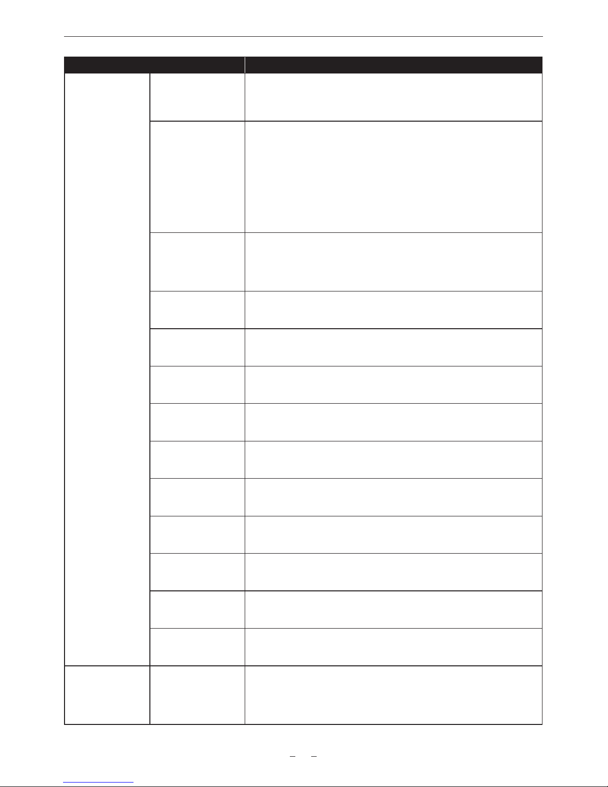
Item Description of settings
[MARKER & CHAR
LVL]
Sets the frame marker and character luminance.
Enabled for [FRAME MARK] only when [FRAME COLOR] is set to [WHITE].
[50%]…[100%] (10% step)
Factory setting: [70%]
[CENTER MARKER] Controls the center mark.
[1]: + (large)
[2]: Open center (large)
[3]: + (medium)
[4]: Open center (medium)
[5]: + (small)
[6]: Open center (small)
[7]: + (very small)
[OFF]: Does not display.
Factory setting: [1]
[SAFETY MARKER] Selects the type of frame for the safety zone marker.
[1]: Box
[2]: Corners
[OFF]: Does not display.
Factory setting: [OFF]
[SAFETY AREA] Sets the size of the safety zone marker.
[80%] - [100%] (1% step, xed aspect ratio)
Factory setting: [90%]
[FRAME MARK] Enables/disables frame marker.
[ON], [OFF]
Factory setting: [OFF]
[FRAME SIG] Sets frame marker aspect ratio.
[1.33:1], [1.44:1], [1.56:1], [1.78:1], [1.85:1], [2.201:1], [2.35:1], [2.39:1]
Factory setting: [2.39:1]
[FRAME COLOR] Sets the color of the frame marker.
[WHITE], [BLACK], [RED], [GREEN], [BLUE], [YELLOW]
Factory setting: [WHITE]
[FRAME LEVEL] Sets the level of the outside of the frame marker.
[0%] - [100%] (10% step)
Factory setting: [100%]
[USER BOX] Displays/hides the user box.
[ON], [OFF]
Factory setting: [OFF]
[USER BOX WIDTH] Sets the width of the user box.
[1]…[100]
Factory setting: [13]
[USER BOX HEIGHT] Sets the height of the user box.
[1]…[100]
Factory setting: [13]
[USER BOX H POS] Sets the horizontal position of the center of the user box.
[−50]…[50]
Factory setting: [0]
[USER BOX V POS] Sets the vertical position of the center of the user box.
[−50]…[50]
Factory setting: [0]
[VF INDICATOR] [INDICATOR SW] Sets whether to display items that will be set by [INDICATOR] in the output from
the <VF> terminal and <VF SDI> terminal.
[ON]: Items are individually displayed/hidden.
[OFF]: Hides all.
Factory setting: [ON]
Page 23
AU-VCXRAW2 Recorder - Getting Started Guide v2.0
23
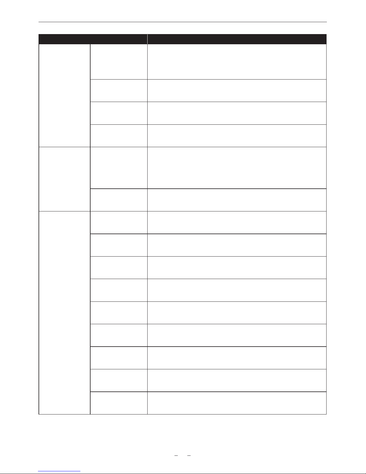
Item Description of settings
[REC TALLY] Displays/hides the method is displaying the recording status.
[RED]: The red tally lamp lights up.
[GREEN]: The green tally lamp lights up.
[CHAR]: The characters [REC] are displayed in the viewnder.
Factory setting: [RED]
[CLIP NAME] Displays/hides clip names.
[ON], [OFF]
Factory setting: [ON]
[INDICATOR OUT SEL] Selects the output destination of the item to set in the [INDICATOR] page:
[VF], [VF SDI], [VF & VF SDI]
Factory setting: [VF & VF SDI]
[REMOTE CTRL] Displays/hides the ROP app control status.
[ON], [OFF]
Factory setting: [ON]
[VF MARKER] [MARKER SW] Sets whether to display markers in the output from the <VF> terminal and <VF
SDI> terminal.
[ON], [OFF]
Factory setting: [ON]
See earlier details of [MON OUT MARKER], which contains the same options as
the [VF MARKER] menu.
[MARKER OUT SEL] Selects the output destination of the marker display.
[VF], [VF SDI], [VF & VF SDI]
Factory setting: [VF & VF SDI]
[VF FOCUS ASSIST] [EXPAND SW] Displays/hides the enlargement display function.
[ON], [OFF]
Factory setting: [OFF]
[- POS] Adjusts the source signal position in an enlarged display.
[0]…[8]
Factory setting: [4]
[- VALUE] Adjusts the enlargement factor.
[x2], [x3], [x4]
Factory setting: [x2]
[- MODE] Sets the enlargement display function mode.
[10SEC], [HOLD], [UNTIL REC]
Factory setting: [10SEC]
[IN COLOR/SQ./MONO
SW]
Displays/hides the advanced assist function (peaking and focus square).
[ON], [OFF]
Factory setting: [OFF]
[- FOCUS IN COLOR
SW]
Displays/hides the peaking function.
[ON], [OFF]
Factory setting: [OFF]
[-- PEAKING VALUE] Sets the peaking function mode.
[LOW], [MID], [HIGH]
Factory setting: [MID]
[-- COLOR SEL] Sets the peaking function color.
[RED], [GREEN], [WHITE]
Factory setting: [RED]
[- FOCUS SQUARES
SW]
Displays/hides the focus square function.
[ON], [OFF]
Factory setting: [OFF]
Page 24
AU-VCXRAW2 Recorder - Getting Started Guide v2.0
24
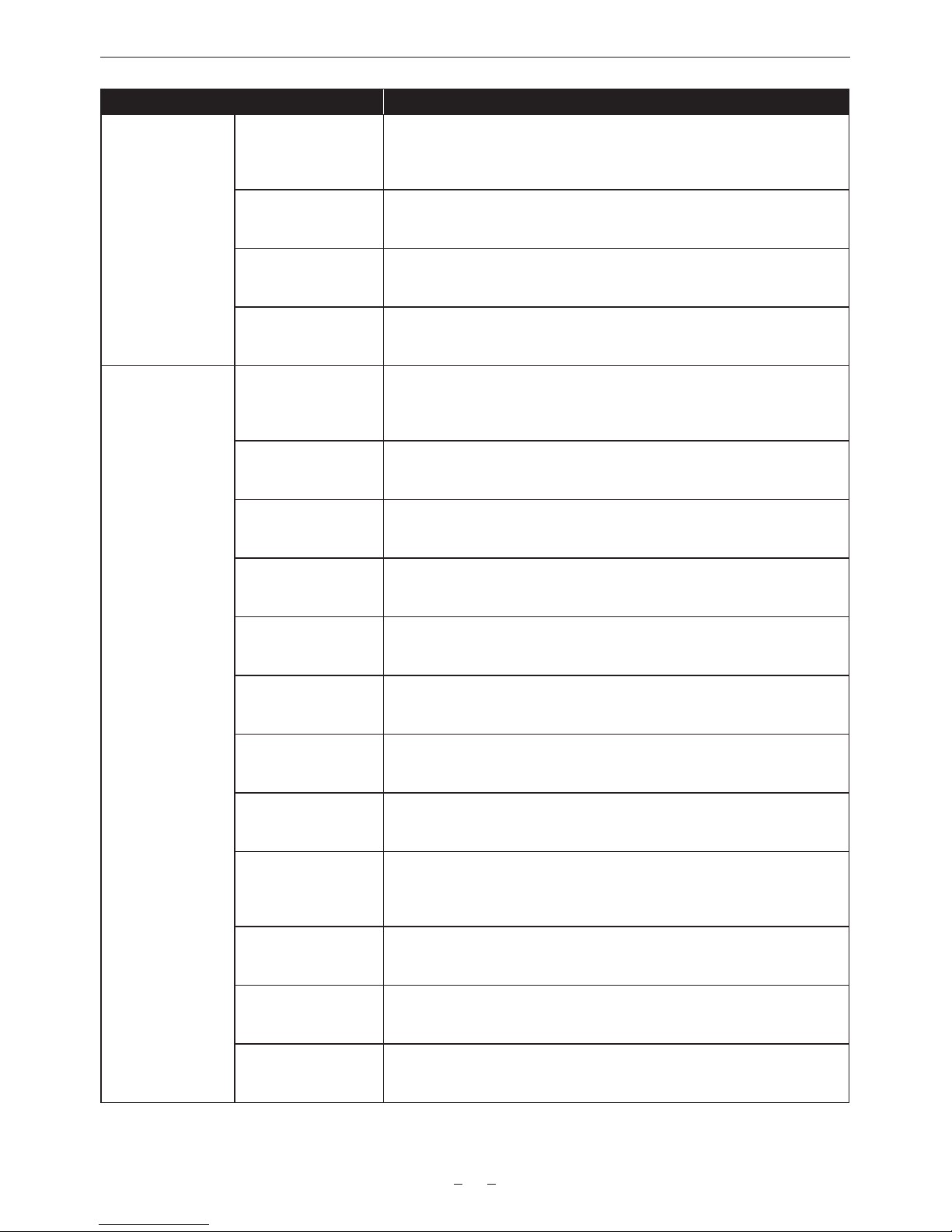
Item Description of settings
[- MONO SW] Enables/disables the monochromatic display function when [IN COLOR/SQ./
MONO SW] is set to [ON].
[ON], [OFF]
Factory setting: [OFF]
[FOCUS BAR SW] Enables/disables the focus bar display function.
[ON], [OFF]
Factory setting: [ON]
[IN COLOR/SQ./MONO
OUT SEL]
Selects the output destination of the advanced assist function.
[VF], [VF SDI], [VF & VF SDI]
Factory setting: [VF & VF SDI]
[FOCUS BAR OUT
SEL]
Selects the output destination of the focus bar display.
[VF], [VF SDI], [VF & VF SDI]
Factory setting: [VF & VF SDI]
[VF EI ASSIST] [ZEBRA SW] Sets whether to superimpose the zebra signal on the output from the <VF>
terminal and <VF SDI> terminal.
[ON], [OFF]
Factory setting: [OFF]
[ZEBRA1 DETECT] Sets the detection level of zebra pattern 1.
[0%] - [109%]
Factory setting: [80%]
[ZEBRA2 DETECT] Sets the extraction level of zebra pattern 2.
[0%] - [109%]
Factory setting: [100%]
[ZEBRA2 MODE] Enables/disables zebra pattern 2 and selects [SPOT].
[ON], [SPOT], [OFF]
Factory setting: [OFF]
[ZEBRA OUT SEL] Selects the output destination of the zebra display.
[VF], [VF SDI], [VF & VF SDI]
Factory setting: [VF & VF SDI]
[WFM SW] Displays/hides waveform monitor.
[ON]/[OFF]
Factory setting: [OFF]
[- TYPE] Sets the display format of the waveform monitor.
[Y], [YGBR]
Factory setting: [Y]
[- TRANSPARENCE] Sets the transparency of the waveform monitor display.
[0%], [25%], [50%], [75%]
Factory setting: [50%]
[Y GET SW] Enables/disables the Y GET display function.
The user box function will not operate when [Y GET SW] is set to [ON].
[ON], [OFF]
Factory setting: [OFF]
[- UNIT] Sets the [Y GET] display unit when [MAIN COLOR] is set to [V-Log].
[STOP], [%]
Factory setting: [STOP]
[- AREA SIZE] Sets the size of area to detect with the Y GET display function.
[S], [M], [L]
Factory setting: [M]
[FALSE COLOR SW] Sets the display of the false color.
[ON], [OFF]
Factory setting: [OFF]
Page 25
AU-VCXRAW2 Recorder - Getting Started Guide v2.0
25
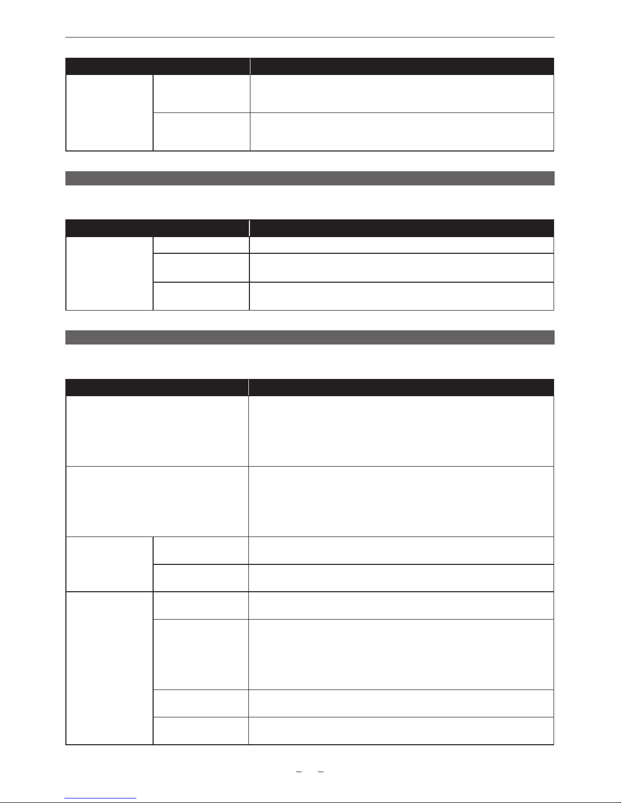
Item Description of settings
[WFM OUT SEL] Selects the output destination of the waveform monitor display.
[VF], [VF SDI], [VF & VF SDI]
Factory setting: [VF & VF SDI]
[FALSE COLOR OUT
SEL]
Selects the output destination of the false color display.
[VF], [VF SDI], [VF & VF SDI]
Factory setting: [VF & VF SDI]
[FILE]
Performs le-related operations such as reading/writing menu settings data from/to an SD memory card.
Item Description of settings
[SETUP FILE] [LOAD(SD CARD)] Selects the setup le saved to the SD memory card and to be read in the camera.
[SAVE(SD CARD)] Overwrites the current setting values in the camera to the le selected from the
setup le le list saved to the SD memory card.
[SAVE AS(SD CARD)] Enters a le name or title name for the le containing the current setting values of
the camera and saves it in the SD memory card as a new setup le.
[PERIPHERAL]
Applies settings related to functions used in conjunction with peripheral devices, such as network and GPS devices.
Item Description of settings
[GPS] Congures internal GPS settings.
[ON]: Activates the GPS operation. Outputs the location information as a signal to
the <SDI OUT> terminal and records it as clip metadata.
[OFF]: Does not activate the GPS operation. Does not output and record the
location information.
Factory setting: [OFF]
[NETWORK SEL] Sets the connection method when connecting the camera with an external device
(such as a computer) via network.
[LAN]: Connects via the <LAN> terminal.
[WLAN]: Connects via wireless LAN.
[OFF]: Does not connect.
Factory setting: [OFF]
[NETWORK FUNC] [USER ACCOUNT] Sets the user account to be used for authentication in the network function of the
camera.
[ACCOUNT LIST] Displays the currently set account name. Also registers new accounts and deletes
accounts.
[LAN PROPERTY] [MAC ADDRESS] Displays the MAC address of the <LAN> terminal on the camera. (Cannot be
changed.)
[DHCP] Sets whether to use automatic acquisition via DHCP. (Mutually exclusive with
[DHCP SERVER] setting)
[ENABLE]: Uses automatic acquisition.
[DISABLE]: Does not use automatic acquisition. Set [IP ADDRESS], [SUBNET
MASK], [DEFAULT GATEWAY], [PRIMARY DNS], and [SECONDARY DNS].
Factory setting: [ENABLE]
[IP ADDRESS] Sets the IP address when [DISABLE] is selected in [DHCP].
Factory setting: [192.168.0.1]
[SUBNET MASK] Sets the subnet mask when [DISABLE] is selected in [DHCP].
Factory setting: [255.255.255.0]
Page 26
AU-VCXRAW2 Recorder - Getting Started Guide v2.0
26
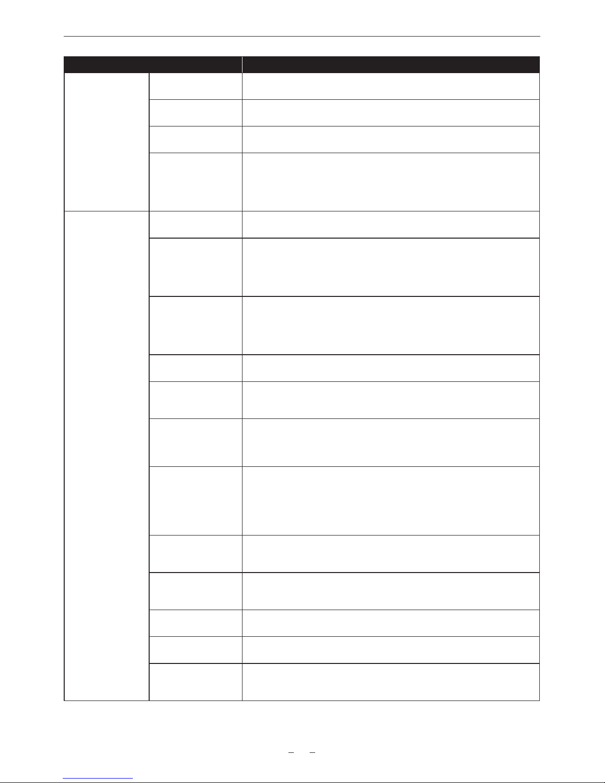
Item Description of settings
[DEFAULT GATEWAY] Sets the default gateway when [DISABLE] is selected in [DHCP].
Factory setting: [192.168.0.254]
[PRIMARY DNS] Sets the primary DNS server when [DISABLE] is selected in [DHCP].
Factory setting: [0.0.0.0]
[SECONDARY DNS] Sets the secondary DNS server when [DISABLE] is selected in [DHCP].
Factory setting: [0.0.0.0]
[DHCP SERVER] Sets whether to use the DHCP SERVER function when connected via wired LAN.
(Mutually exclusive with [DHCP] setting)
[ENABLE]: Uses the DHCP SERVER function.
[DISABLE]: Does not use the DHCP SERVER function.
Factory setting: [DISABLE]
[WIRELESS
PROPERTY]
[MAC ADDRESS] Displays the MAC address of the wireless LAN adaptor connected to the camera.
(Cannot be changed.)
[TYPE] Sets the connection method.
[DIRECT]: Accesses to the network function of the camera directly from a
smartphone, tablet, or computer.
[INFRA]: Connects to the wireless access point.
Factory setting: [DIRECT]
[SSID INPUT MODE] Sets the setting method of SSID.
When [TYPE] in [WIRELESS PROPERTY] is set to [INFRA], this item can be set.
[SELECT]: Selects the setting from the access point list.
[MANUAL]: Enters the setting manually.
Factory setting: [SELECT]
[SSID] Displays network name (SSID).
Factory setting: [AU-VREC1]
[BAND] Switches between two transmission methods (2.4 GHz or 5 GHz).
[2.4GHz], [5GHz]
Factory setting: [2.4GHz]
[CHANNEL(2.4GHz)] Sets the channel to be used when [2.4GHz] is selected in [BAND] and connected
with the wireless LAN.
[AUTO], [CH1], [CH6], [CH11]
Factory setting: [AUTO]
[CHANNEL(5GHz)] Sets the channel to be used when [5GHz] is selected in [BAND] and connected
with the wireless LAN.
The selection differs depending on the installed wireless module.
[AUTO], [CH36], [CH40], [CH44], [CH48], [CH149], [CH153], [CH157], [CH161],
[CH165]
Factory setting: [AUTO]
[ENCRYPTION] Sets the encryption format.
[WPA-TKIP], [WPA-AES], [WPA2-TKIP], [WPA2-AES], [NONE]
Factory setting: [WPA2-AES]
[ENCRYPT KEY] Sets the encryption key. Set the key using a string of 8 to 63 characters or a
hexadecimal number with 64 digits.
Factory setting: [01234567890123456789abcdef]
[IP ADDRESS] Sets the IP address when [DISABLE] is selected in [DHCP].
Factory setting: [192.168.0.1]
[SUBNET MASK] Sets the subnet mask when [DISABLE] is selected in [DHCP].
Factory setting: [255.255.255.0]
[DEFAULT GATEWAY] Sets the default gateway when [INFRA] is selected in [TYPE] and [DISABLE] is
selected in [DHCP].
Factory setting: [192.168.0.254]
Page 27
AU-VCXRAW2 Recorder - Getting Started Guide v2.0
27
Item Description of settings
[PRIMARY DNS] Sets the primary DNS server when [INFRA] is selected in [TYPE] and [DISABLE]
is selected in [DHCP], or when [ENABLE] is selected in [DHCP] and the primary
DNS server cannot be obtained.
Factory setting: [0.0.0.0]
[SECONDARY DNS] Sets the secondary DNS server when [INFRA] is selected in [TYPE] and
[DISABLE] is selected in [DHCP], or when [ENABLE] is selected in [DHCP] and
the primary DNS server cannot be obtained.
Factory setting: [0.0.0.0]
[DHCP SERVER] Sets whether to use the DHCP SERVER function when connected via wireless
LAN.
[ENABLE]: Uses the DHCP SERVER function.
[DISABLE]: Does not use the DHCP SERVER function.
Factory setting: [ENABLE]
[NETWORK TOOLS] [STATUS DISPLAY] Displays the network status.
[INITIALIZE] Restores the network setting status to the factory settings.
Recording
With the Capture Drive formatted, press either of the red REC buttons to begin a recording. The light on top of the AU-VCXRAW2 will be
red during recording. Press the red REC button again to end the recording.
Playback
Press the PLAY button to open a list of clips for playback. Scroll the list to select a clip and press the jog wheel to begin playback.
The light on the top of the AU-VCXRAW2 will be green during playback.
Errors and Warnings
In the event of an error, the word ERROR will be shown on the display. If this occurs during recording it is recommended to remove
the Capture Drive and check the status of the recordings in a Capture Drive Dock or S/XL-Series (rather than continuing to use it
immediately). Codex Support can be contacted at [email protected]
If the issue does not occur during recording then restart the camera.
Record times to Capture Drive
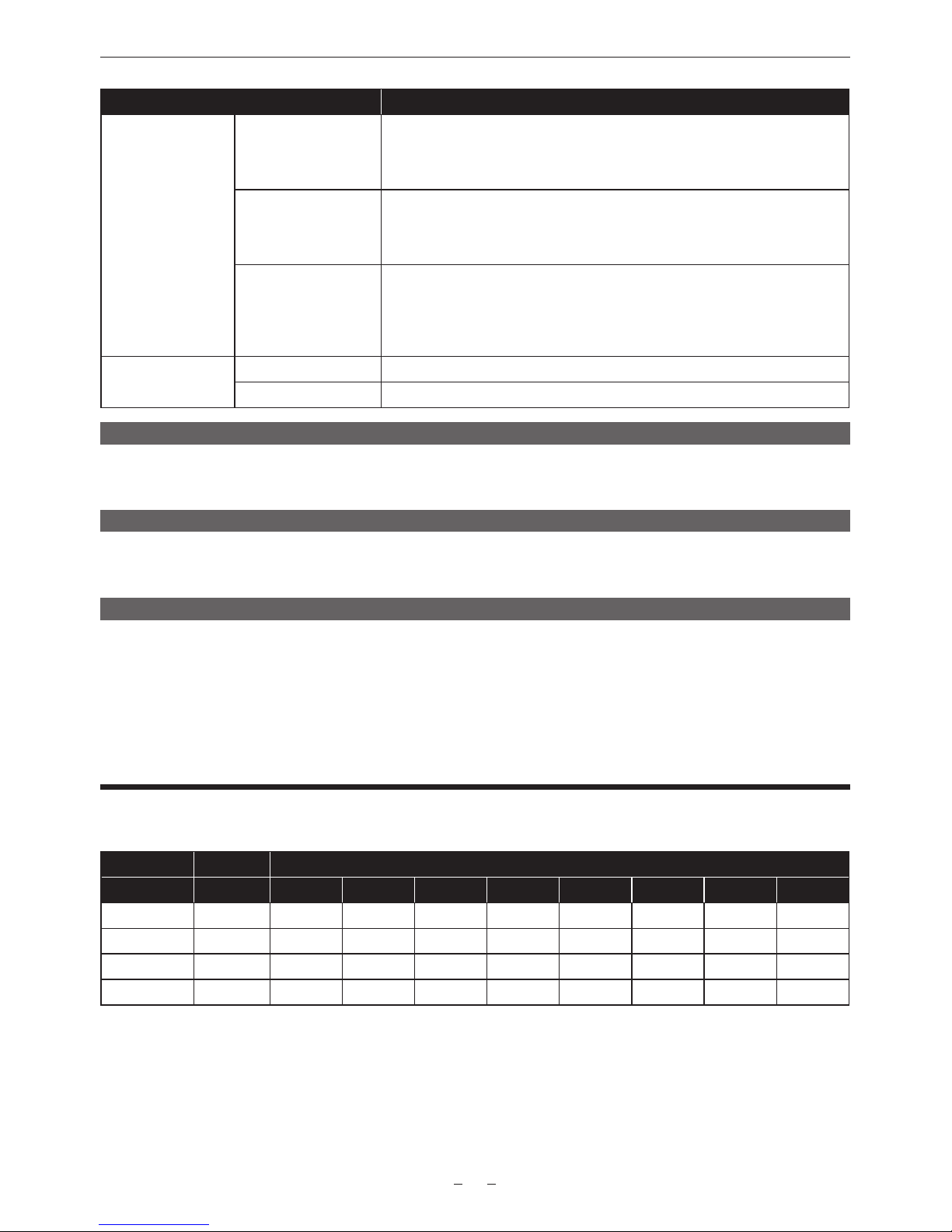
The table below details the RAW record times available to a Capture Drive with 1TB capacity:
Frame Rate
Resolution Bit Depth 23.98/24 25 29.97/30 48 50 59.94/60 96 120
4096x2160 12-bit 50 48 40
4096x2160 10-bit 56 53.5 44.5 28 26.5 44 14 11
3840x2160 12-bit 53 50.5 42
3840x2160 10-bit 59.5 57 47.5 29.5 28.5 23.5 14.5 11.5
Page 28
AU-VCXRAW2 Recorder - Getting Started Guide v2.0
28
Using Codex Production Suite Software
Codex Production Suite software running on a Mac with Capture Drive 2.0 Dock (see below), or a Codex S-Series or XL-Series
hardware is required to read the RAW recordings made to Capture Drive 2.0 media.
Go to https://codex.online/software to register and download the latest software for these products. There are installation instructions
available from this web page. An overview is provided for using Codex Production Suite with Capture Drive Dock on Mac as part of the
workow with the VariCam Pure. Codex Production Suite software can be used for a wide range of functions with recorded VariCam
Pure RAW material. For example:
• Metadata editing.
• Playback to attached display or HD-SDI monitor, including application of LUTs and CDL adjustment.
• Transcoding to other le types such as ProRes, DNxHD MXF, and H264.
• Archive to disk or LTFS tape.
Codex Production Suite is available to all users with a Codex Connect subscription, which includes direct Support, software updates,
online tutorials, and TeamViewer access from our global support team: https://codex.online/products/connect
Supporting documentation: https://codex.online/support/production-suite-user-guides
Video tutorials: https://codex.online/support/production-suite-tutorials
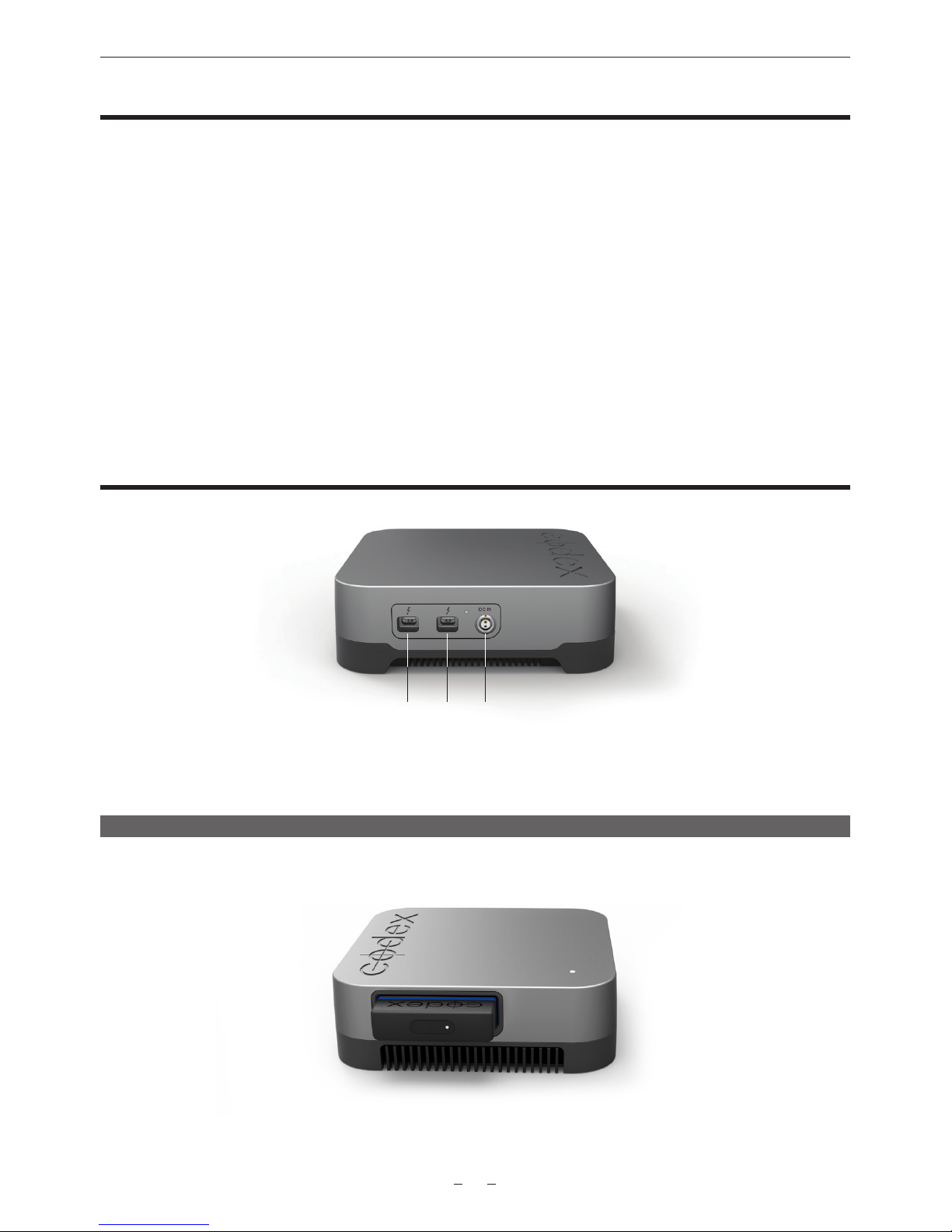
Connecting a Codex Capture Drive Dock
Thunderbolt Ports DC Power Supply
Connect the included DC power supply to the DC IN connector of the Capture Drive 2.0 Dock. There are two Thunderbolt Ports available
- connect one to a Mac computer that has the required Codex software installed. The other Thunderbolt port can be used to connect to
other Thunderbolt devices, such as a monitor or storage.
Loading and unloading a Capture Drive from the Dock
Insert a Codex Capture Drive into the Dock and it will begin loading automatically. During this time the LED will ash blue. When it is
loaded the LED will ash green, and this typically takes 5-10 seconds.
Codex Capture Drive 2.0 Dock with mounted Capture Drive 2.0
Page 29
AU-VCXRAW2 Recorder - Getting Started Guide v2.0
29
The LED on a Capture Drive ashes green quickly when it is reading/writing data. Do not unload a Capture Drive when it is reading/
writing as this can compromise data integrity.
To unload, press the eject button on the end of the Capture Drive or go to the Storage screen of Codex Production Suite (/Applications/
Codex/Vault Platform->Storage), click to select the media, and click the Wrench->Eject button. The LED will ash blue while it unloads.
When the LED is solid blue it is safe to remove the Capture Drive.
Always eject the Capture Drive correctly before removing it from the Dock.
WARNING: INCORRECT REMOVAL OF THE CAPTURE DRIVE MAY RESULT IN CORRUPTION OR DATA LOSS.
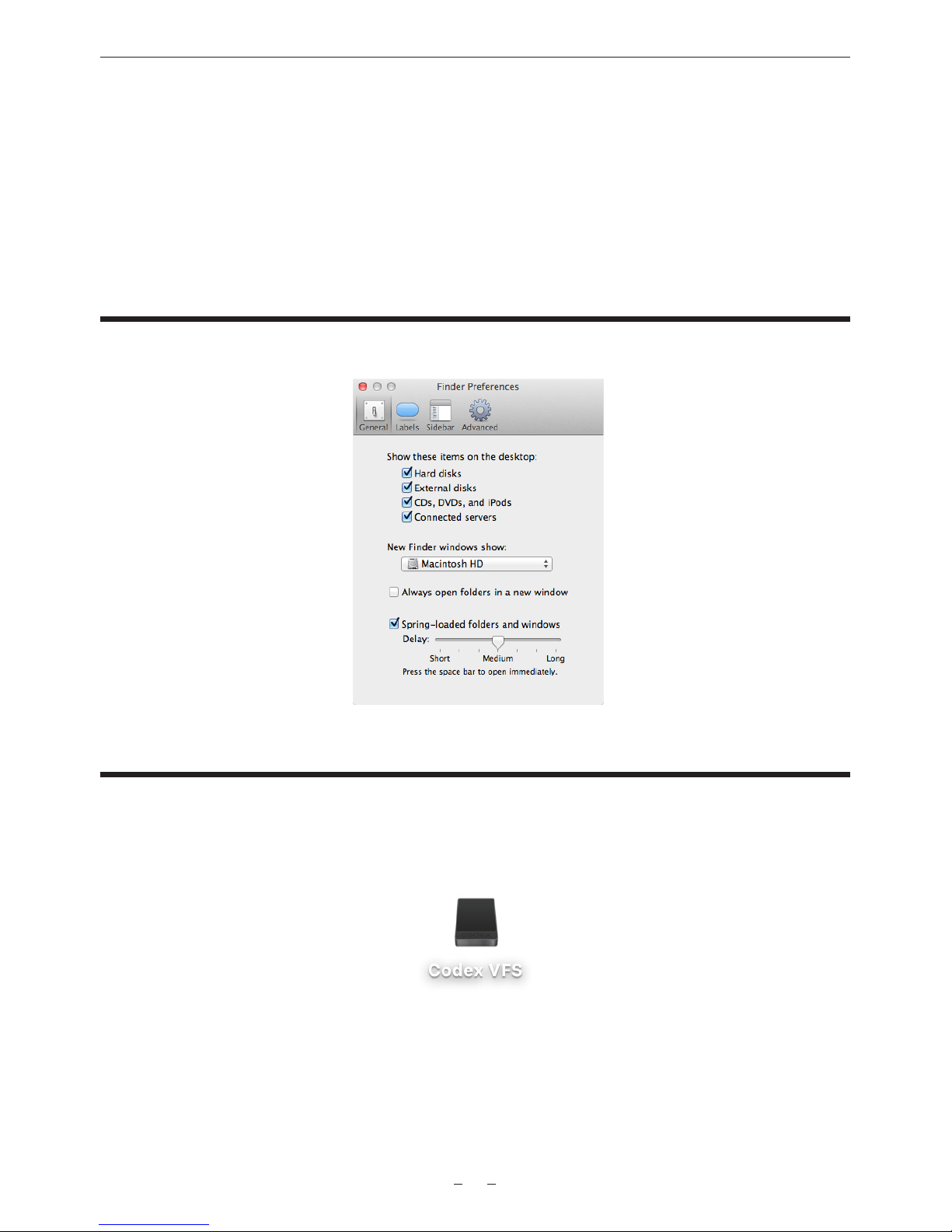
Finder Preferences
For ease of use it is recommended to set up the Finder Preferences so that External disks are shown on the Desktop:
Copying les from the Capture Drive
Codex Production Suite provides a complete set of tools for managing your VariCam Pure RAW data, from copying and archiving, to
playback, colour correction, and transcoding. See the earlier section ‘Using Codex Production Suite’ for more details.
When Codex Production Suite is installed the Codex VFS drive will be shown on the Desktop:
The Codex VFS drive is always shown, but will be empty until a Capture Drive containing RAW recordings is loaded. After loading the
Capture Drive the les are available to be copied from the Codex VFS drive.
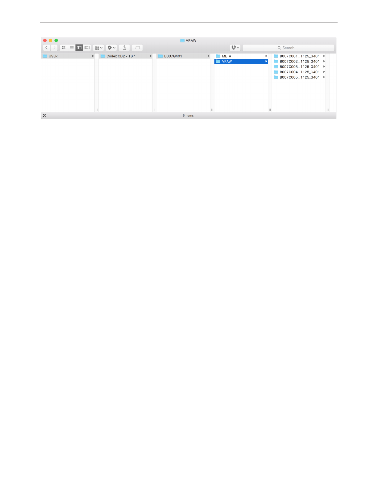
Files are presented in a Reel folder (B007G401 in the example below). Within this are folders containing images, audio, metadata (as
well as LUT information when using the VariCam 35):
Page 30
AU-VCXRAW2 Recorder - Getting Started Guide v2.0
30
File types are presented in separate directories under the top level Reel directory. For example:
A001G4A3/
VRAW/
A001_C001_140612_G4A3
A001_C001_140612_G4A3.0018123.vrw
A001_C001_140612_G4A3.0018124.vrw
A001_C001_140612_G4A3.0018125.vrw
...
A001_C002_140612_G4A3
A001_C002_140612_G4A3.0019739.vrw
…
BWF/
A001_C001_140612_G4A3_A12.wav
A001_C001_140612_G4A3_A34.wav
A001_C002_140612_G4A3_A12.wav
A001_C002_140612_G4A3_A34.wav
...
META/
A001_C001_140612_G4A3.XML
A001_C001_140612_G4A3.VLT
A001_C001_140612_G4A3.CDL
A001_C002_140612_G4A3.XML
A001_C002_140612_G4A3.VLT
A001_C002_140612_G4A3.CDL
...
Note: example assumes clips have four channels of audio, and stereo BWF delivery option has been selected.
Copy the top level Reel folder (B007G401 in the above example) to another storage device to back-up the entire package of image,
audio, metadata, and LUT les.
Any copy tool can be used to back-up les from the Codex VFS drive to another storage device.
Page 31

AU-VCXRAW2 Recorder - Getting Started Guide v2.0
31
Notes
Page 32

AU-VCXRAW2 Recorder - Getting Started Guide v2.0
32
AU-VCXRAW2 Recorder Getting Started Guide v1.0. E & OE. Codex reserves the right to alter the specification at any time and without prior notice.
© Copyright Codex. October 2016. All other trademarks used are the property of their respective owners.
Codex Recorder (AU-VCXRAW2) for Panasonic VariCam Pure - Getting Started Guide v2.0. E & OE.
Codex reserves the right to alter specication at any time and without prior notice.
London Ofce 60 Poland Street London W1F 7NT United Kingdom Tel +44 203 7000 989
Los Angeles Ofce 3450 Cahuenga Boulevard West Unit 103 Los Angeles CA 90068 Tel +1 323 283 8939
https://codex.online [email protected]
 Loading...