

Page 1

USER GUIDE
ACTION CAM
VERSION 2015.03.03
CODEX USER GUIDE - ACTION CAM 2015.03.03
PAGE 1
Page 2

Safety Warnings
Please observe any warnings and follow all instructions.
• Do not use this equipment near water and clean only with a dry cloth.
• Do not block any ventilation openings. Install in accordance with the manufacturer’s instructions.
• Do not install near any heat sources such as radiators, heat registers, stoves, or other equipment (including ampliers)
that produce heat.
• Do not expose to excessive vibration, or drop this product.
• Do not defeat the safety purpose of the polarised or grounding-type plug. A polarised plug has two blades with one wider
than the other. A grounding-type plug has two blades and a third grounding prong. The wide blade, or the third prong, is
provided for your safety.
• If the provided plug does not t into your outlet, consult an electrician for replacement of the obsolete outlet.
• Protect the power cord from being walked on or pinched, particularly at plug ends, convenience receptacles, and the point
where they exit from the equipment.
• Only use attachments/accessories specied by the manufacturer.
• Use only with the cart, stand, tripod, bracket, or table specied by the manufacturer, or sold with the equipment.
• Unplug this equipment during lightning storms or when not in operation for long periods of time.
• Refer all servicing to qualied service personnel. Servicing is required when the equipment has been damaged in any way,
such as power-supply cord or plug is damaged, liquid has been spilled or objects have fallen into the equipment,
has been exposed to rain or moisture, does not operate normally, or has been dropped.
• To reduce the risk of re or electric shock, do not expose equipment to rain or moisture.
• To avoid electrical shock, do not attempt to open this equipment. Refer servicing to qualied personnel only.
WARNING: Remote Heads and Capture Drives may become hot during use.
Disclaimer
Codex products are continually developed to remain at the forefront of the industry, and as such the information in this guide
is subject to change without notice. Whilst Codex endeavour to ensure that all documentation provided is correct at the time of
writing, this document is not guaranteed to be error-free.
Codex does not assume responsibility for issues or losses due to misinterpretation of the information in this document, errors in
this document, or incorrect conguration or installation of the equipment described herein.
Please report any errors found in this document to [email protected]
Support and Servicing
For assistance with your Action Cam please contact [email protected]
CODEX USER GUIDE - ACTION CAM 2015.03.03
PAGE 2
Page 3
Warning Notes on bright lights, direct sunlight exposure, and laser beams
The following warnings and information are provided as guidance to yield the best possible results from the Action Cam CCD
(Charge Coupled Device) image sensor.
Working with High Energy Light Sources
High energy light beams may damage the CCDs - even when the Action Cam system is not powered on! If you shoot a scene
that includes a bright light beam, be careful not to let the beam be directed into the lens of the camera. If you take off the lens,
be sure that the protection cap is immediately put back onto the lensmount.
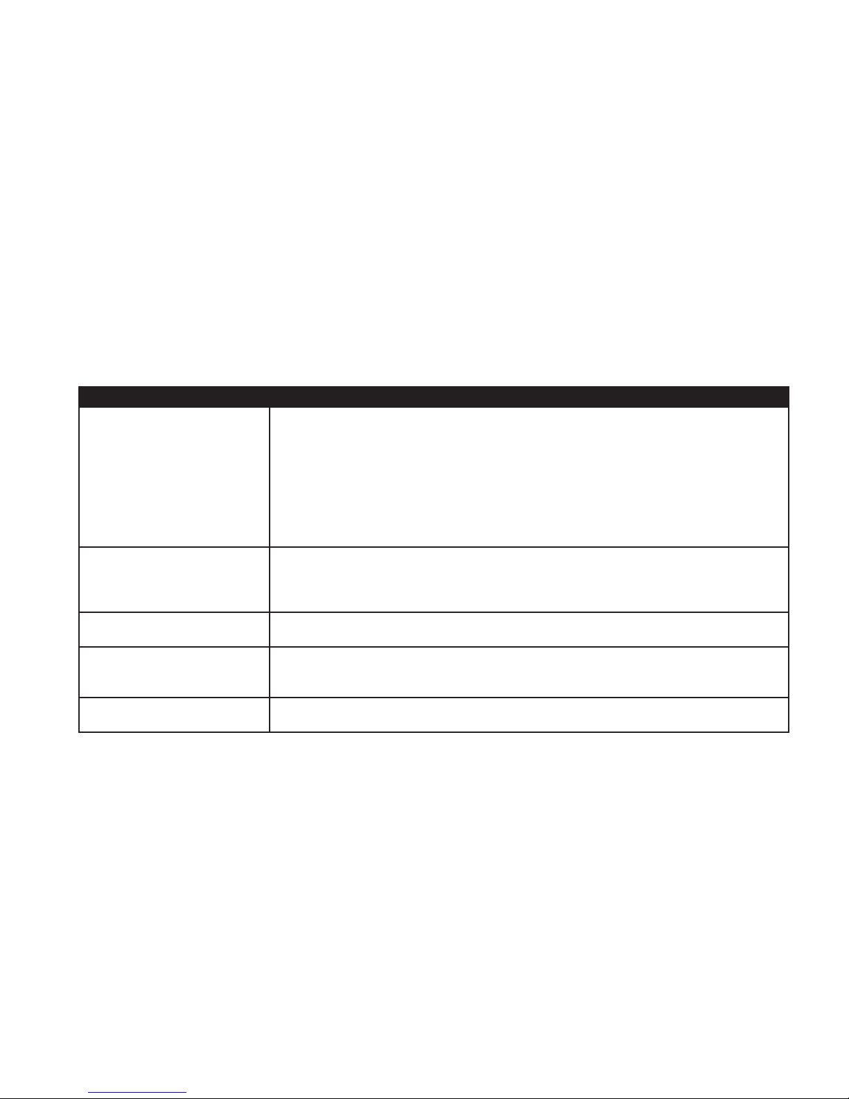
Phenomena Specific to CCD Image Sensors
The following phenomena that may appear in images are specic to CCD image sensors. They do not indicate malfunctions.
Image phenomena Information
White ecks
Although the CCD image sensors are produced with high-precision technologies, ne
white ecks may be generated on the screen in rare cases, caused by cosmic rays. This is
related to the principle of CCD image sensors and is not a malfunction.
The white ecks especially tend to be seen:
Smear
Oversaturation dot
Oversaturation area
Aliasing
• when operating at a high environmental temperature
• when you have raised the sensitivity
When an extremely bright object, such as a strong spotlight or ashlight, is being shot,
vertical tails may be produced on the screen, or the image may be distorted.
In extreme cases of light saturation, the centre of a bright element can appear black.
In extreme cases of light saturation on the edges of the sensor, the bright element can
appear black or distorted.
When ne patterns, stripes, or lines are shot, they may appear jagged or icker.
CODEX USER GUIDE - ACTION CAM 2015.03.03
PAGE 3
Page 4

Contents
Safety Warnings ........................................................................................2
Disclaimer ...................................................................................................2
Support and Servicing..............................................................................2
Warning Notes on bright lights, direct sunlight exposure, and
laser beams ................................................................................................ 2
1. Introduction ....................................................................................... 5
2. Product Diagrams ............................................................................ 6
2.1 Remote Head .................................................................................... 6
2.2 Camera Control Recorder ..............................................................7
2.3 Control Panel ....................................................................................8
3. Hardware Setup ...............................................................................9
3.1 Power ..................................................................................................9
3.2 Cable Length .....................................................................................9
3.3 Connecting the Hardware .............................................................. 9
3.4 Remote Head to Camera Control Unit ......................................10
3.5 Timecode Connection ................................................................... 10
3.6 Shutter Synchronization ...............................................................10
3.7 Connection Examples ...................................................................11
13. Mounting Options ......................................................................... 30
13.1 Cheeseplate Mount ....................................................................... 30
13.2 Vocas Mount .................................................................................. 30
14. Dimensions ......................................................................................31
14.1 Remote Head Dimensions ...........................................................31
14.2 Camera Control Recorder Dimensions ......................................31
15. Technical Specifications ...............................................................32
15.1 Remote Head Specification .........................................................32
15.2 Camera Control Recorder Specification ....................................32
16. Colour Management ......................................................................33
16.1 Video Output Code Distribution Chart .......................................33
16.2 “Cineon” Equivalence ....................................................................34
16.3 Special Values ................................................................................34
16.4 Use of Exposure Index .................................................................34
16.5 Log To Linear Conversion ............................................................ 35
16.6 Linear To Log Conversion ............................................................ 35
16.7 Conversion Variables .................................................................... 35
17. Warning and Error Messages .................................................... 36
18. Connector pin-outs ........................................................................37
3.8 Installing Lenses ............................................................................13
3.9 Adjusting the Lens Scale Position .............................................13
3.10 Adjusting the Flange Back Distance .........................................14
4. Power On and Off ..........................................................................14
5. Menu System..................................................................................15
5.1 Overview ..........................................................................................15
5.2 Setup ................................................................................................16
5.3 Monitor .............................................................................................21
6. Loading and Unloading Media ....................................................25
7. Preparing for Recording ...............................................................26
8. Setting the Frame Rate ................................................................26
9. Recording ........................................................................................27
10. Playback ..........................................................................................28
11. Remote Head LED Indicators ......................................................28
12. Recommended Settings ...............................................................29
Appendix
A1. Flange Back Distance and Back Focus Adjustment ............ 38
A2. Recommended Test Charts ........................................................ 39
CODEX USER GUIDE - ACTION CAM 2015.03.03
PAGE 4
Page 5

1. Introduction
Welcome to this guide for Codex Action Cam - a complete shooting and capture solution for
situations that require a compact form factor and low weight.
Codex Action Cam itself is a tiny remote head camera for shooting at up to 60fps. The output is
1920x1080 12-bit RAW for exceptional quality.
It comes packaged with the Codex Camera Control Recorder that delivers full remote control of
the camera, plus the proven workow of the industry-standard Codex recorder.
The Codex Action Cam is ideal for:
• Point Of View and Action Camera; the creative possibilities are endless.
• Witness Camera; trifocal rig with two Codex Action Cams capturing depth information that is
invaluable for VFX compositing and stereoscopic conversion.
• Native S3D; with Action Cam, 3D shooting is easy. Connect two Camera heads to the Codex
Camera Control Recorder, and the signals undergo exactly the same processing.
Action Cam makes back focus adjustment quick, easy and precise, thanks to a special
mechanism consisting of a sturdy locking lever, rmly securing the adjustment, and an
accurate back focus wheel that rotates independently of the lens mount.
The Action Cam is compatible with C-Mount lenses for professional production, giving you
everything you expect from larger lenses in a small form factor. A PL mount adaptor is available
to allow the use of Ultra 16 and 16mm lenses.
CODEX USER GUIDE - ACTION CAM 2015.03.03
PAGE 5
Page 6
2. Product Diagrams
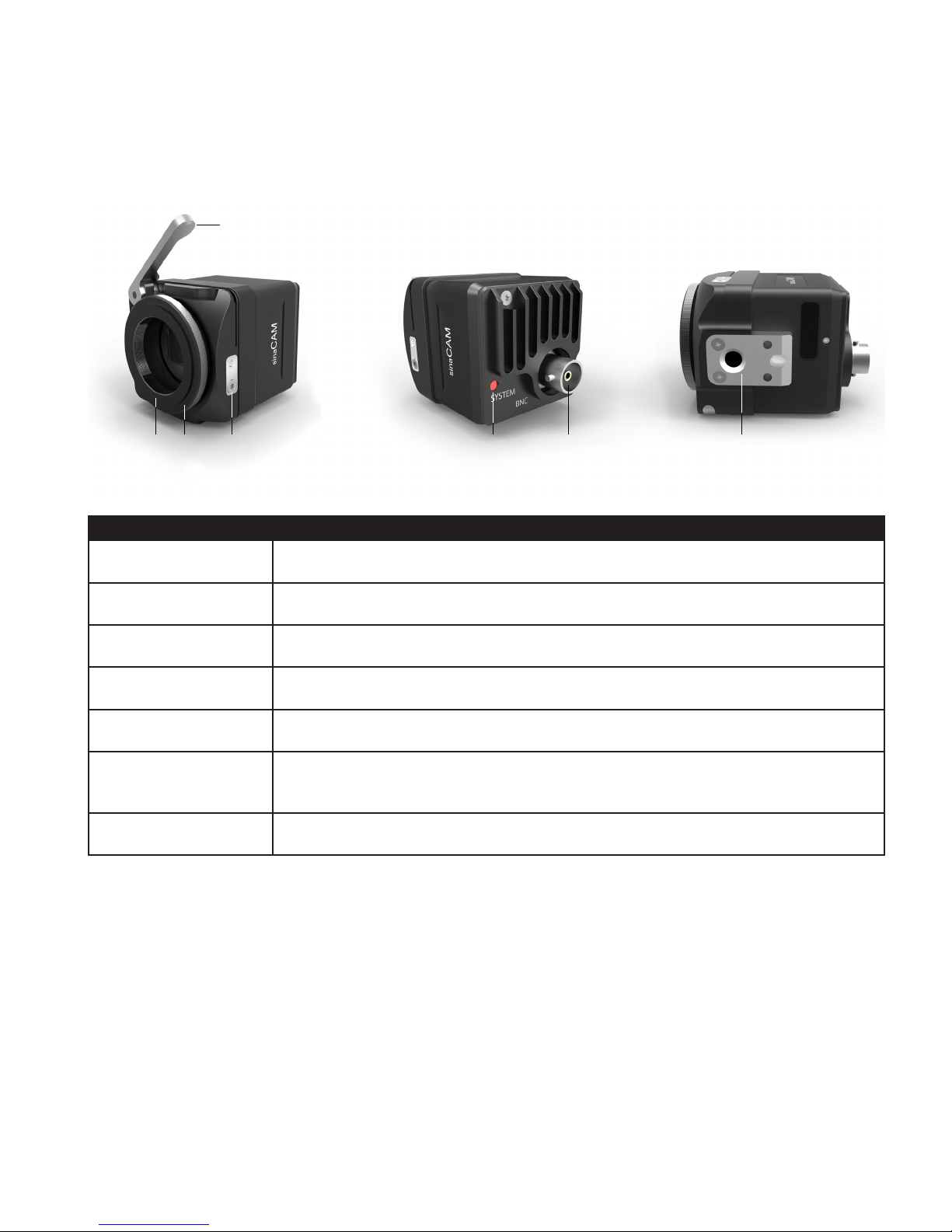
2.1 Remote Head
A
BC D E F G
Feature Description
Locking lever (A) Locking/unlocking the adjustment ring
Flange back adjustment
ring (B)
Lens mount (C) Standard C-mount thread
Lens mount lock (D) Allows for lens scale position alignment in 30 degree steps
System LED (E) Glows continuously when on, ashes during link detection and in case of malfunction.
CoaXPress interface (F) For connection with Camera Control Recorder via 75 Ohm coaxial cable with BNC
Bottom mount (G) 1/4” thread for attaching tripod, handle, base-plate, etc.
Rotates independently of C-mount and lens
plug
CODEX USER GUIDE - ACTION CAM 2015.03.03
PAGE 6
Page 7
2.2 Camera Control Recorder
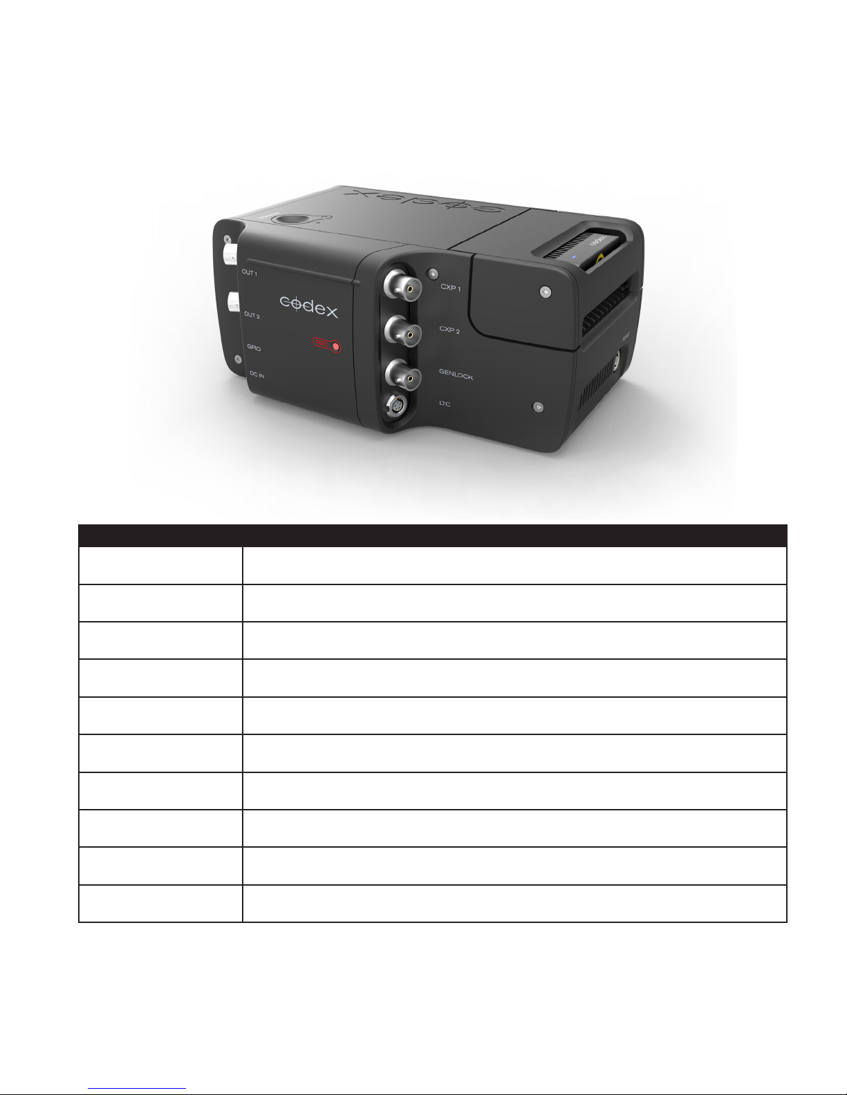
The Camera Control Recorder will be referred to as the CCR for the remainder of this user guide, for brevity.
Connector Description
CXP 1 For connection to Remote Head 1
CXP 2 For connection to Remote Head 2
GPIO For connection of external recorder trigger
LTC For Timecode Input during record and Output during playback
GENLOCK For connection of external Genlock sync source
OUT 1 For connection to HD video monitor for Remote Head 1 image
OUT 2 For connection to HD video monitor for Remote Head 1 or 2 image
DC IN 10-34V Power Input
RS422 For connection to Codex Control Panel (CDX-P065)
NETWORK For connection to computer for remote control and software updates
The Action Cam CCR looks similar to the Codex Onboard S recorder but is functionally different. Action Cam
Remote Heads cannot be used with an Onboard S recorder, and other cameras cannot be used with the Action
Cam CCR.
CODEX USER GUIDE - ACTION CAM 2015.03.03
PAGE 7
Page 8
2.3 Control Panel
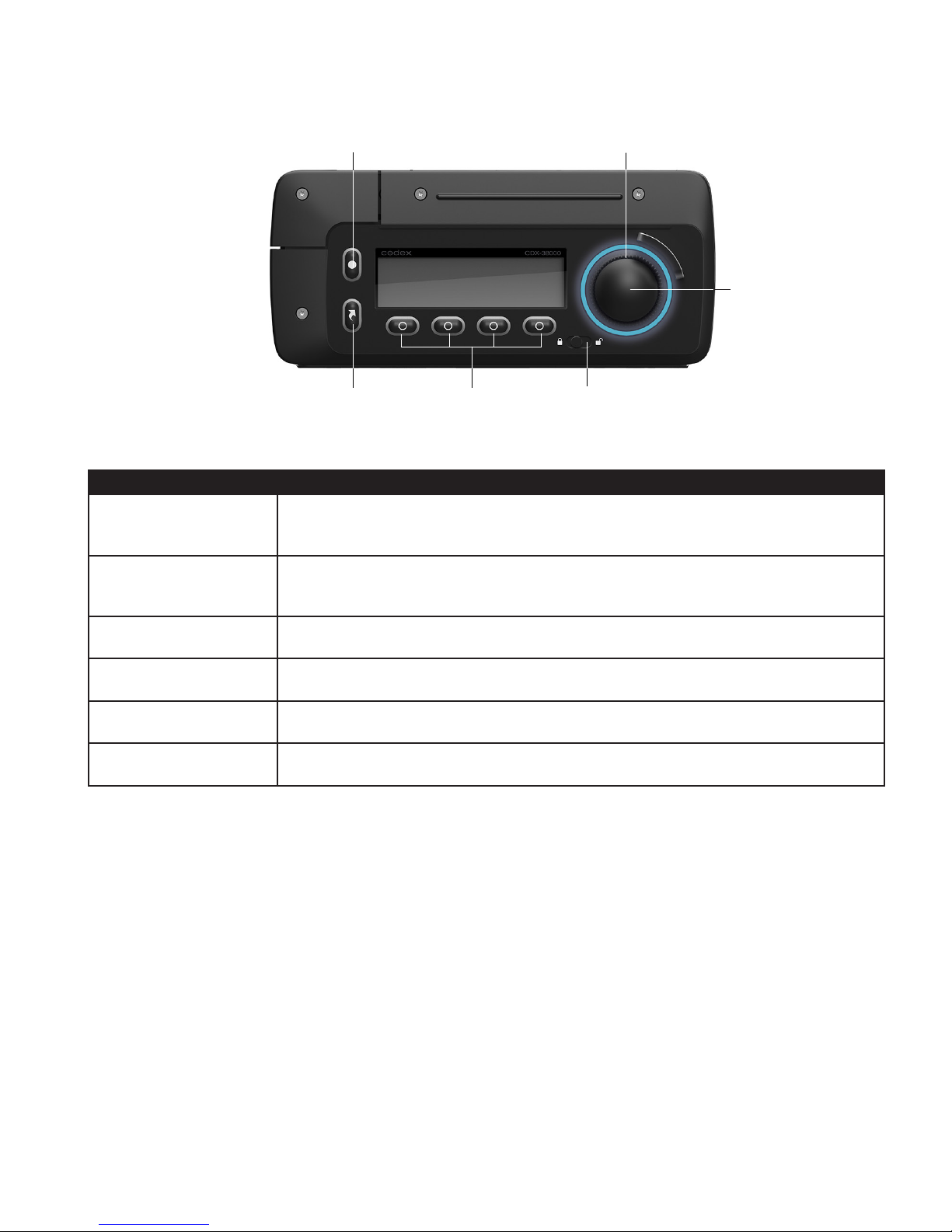
JOG WHEEL (TURN)RECORD
STOP/SELECT (PRESS)
MAIN MENU
Button Description
RECORD When on Monitor screen press to start recording. From other menu screens press as
a shortcut to go to Monitor screen
MAIN MENU Press to access the four Main Menu options under the display (Monitor, Play, Setup,
Storage)
MULTI-FUNCTION For access to contextual options for that menu
HOLD Slide to lock all Control Panel buttons
JOG WHEEL Rotate to navigate through menus, or jog during playback
STOP/SELECT Press to stop recording. In other menus press to select the menu item
For further details please refer to the section ‘Menu System’.
MULTI-FUNCTION HOLD
CODEX USER GUIDE - ACTION CAM 2015.03.03
PAGE 8
Page 9

3. Hardware Setup
3.1 Power
The Action Cam CCR requires an input voltage of 10-34V.
If powering from mains electricity use only the CDX-P099 power supply available from Codex.
The Action Cam CCR supplies power via the CoaXPress link to each of the Remote Heads. Therefore DO NOT
connect from the CXP 1 or CXP 2 connections to a device other than an Action Cam Remote Head, as this may
cause damage either to the CCR or to the connected equipment.
3.2 Cable Length
The maximum cable length between the Remote Head and Camera Control Recorder is limited by the signal
attenuation and the conductor DC resistance of the cable.
Maximum cable length as limited by signal attenuation (rule of thumb):
Max. cable length = 25 dB / attenuation at 1.5 GHz
Maximum cable length as limited by conductor DC resistance (rule of thumb):
Max. cable length = 8 Ω / conductor DC resistance
Example calculation for Belden 1505F Flexible cable:
– Nom. attenuation at 1.5 GHz: 13.300 dB / 100 ft
– Nom. conductor DC resistance: 12.2 Ω / 1000 ft
Max. cable length = 25 dB / (13.300 dB / 100 ft) = ~188 ft (57 m)
Max. cable length = 8 Ω / (12.2 Ω / 1000 ft) = ~656 ft (200 m)
The lower of the two values determines the approximate maximum cable length, in this example 188 ft (57 m).
3.3 Connecting the Hardware
Follow these guidelines when connecting the Action Cam hardware:
• Before connecting the hardware ensure that all components are switched off.
• Connect the Remote Head(s) and other accessories to the CCR.
• Switch on all accessories and the CCR.
CODEX USER GUIDE - ACTION CAM 2015.03.03
PAGE 9
Page 10
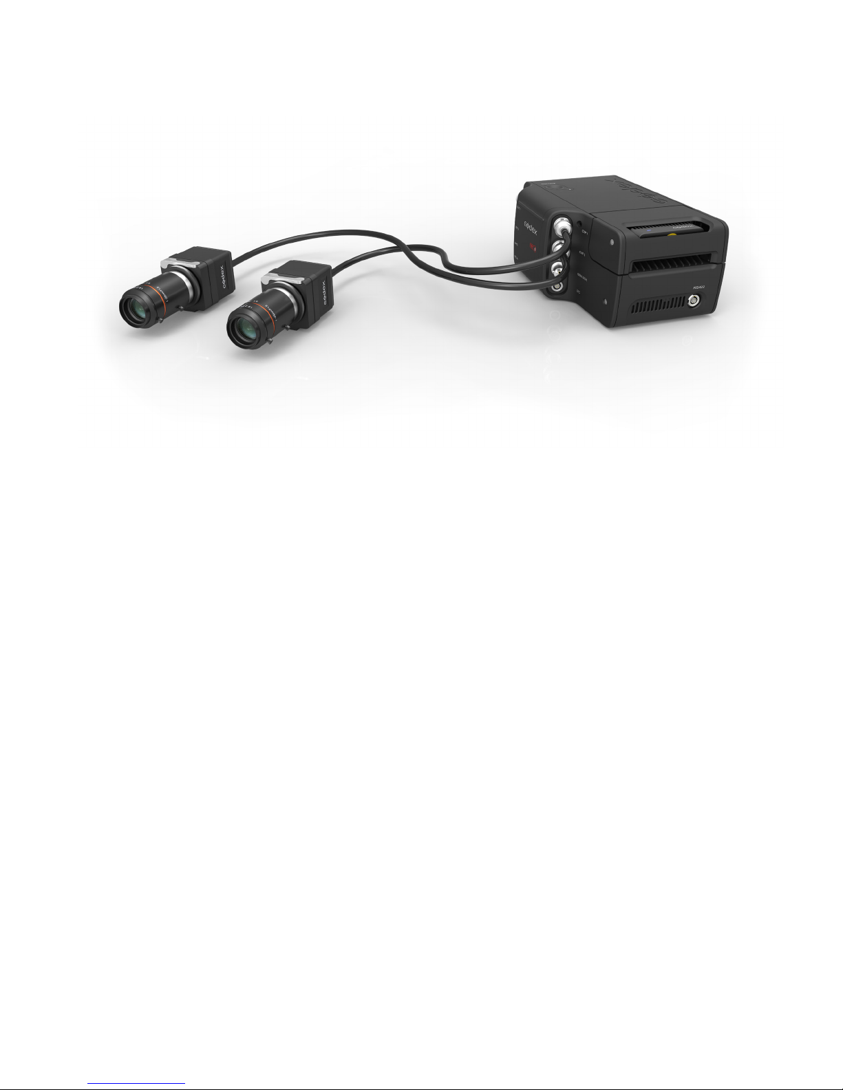
3.4 Remote Head to Camera Control Unit
REMOTE HEAD 2
> CXP 2
Note: Only the Action Cam Remote Head is compatible with the CCR. No other camera signal will be accepted by
the CCR.
REMOTE HEAD 1
> CXP 1
3.5 Timecode Connection
An external LTC timecode source can be connected to Action Cam using the included cables.
The system will automatically sync to an LTC input. This can be jam sync’d and the timecode will continue to run,
or the LTC source can be left connected.
For making a custom cable please refer to the section ‘Connector Pin Outs’.
3.6 Shutter Synchronisation
There are two ways to achieve shutter synchronisation of the Action Cam with other camera systems.
The general method of synchronising cameras is through the use of a Genlock signal connected to all systems.
The SYNC input on the CCR accepts standard analog SD/HD video signals (NTSC, PAL, 480p, 576p, 720p, and
1080i/p/psF) with either bi-level (black bursts) or tri-level sync. In the Action Cam menu Setup->Video->Cam Sync
should be set to Genlock for the Remote Heads to synchronize their shutters to the Genlock input signal.
If using an ARRI ALEXA the camera outputs a sync signal via the RS outputs during recording and this can be
connected to the GPIO socket of the CCR. In the Action Cam menu Setup->Video->Cam Sync should be set to RS
for the Remote Heads to synchronize their shutters with the ALEXA.
Note: if synchronising the Action Cam to the ALEXA RS output the exposure level for the Action Cam should be set
during a test when the ALEXA is recording (the ALEXA only outputs the RS sync signal when it is recording).
CODEX USER GUIDE - ACTION CAM 2015.03.03
PAGE 10
Page 11
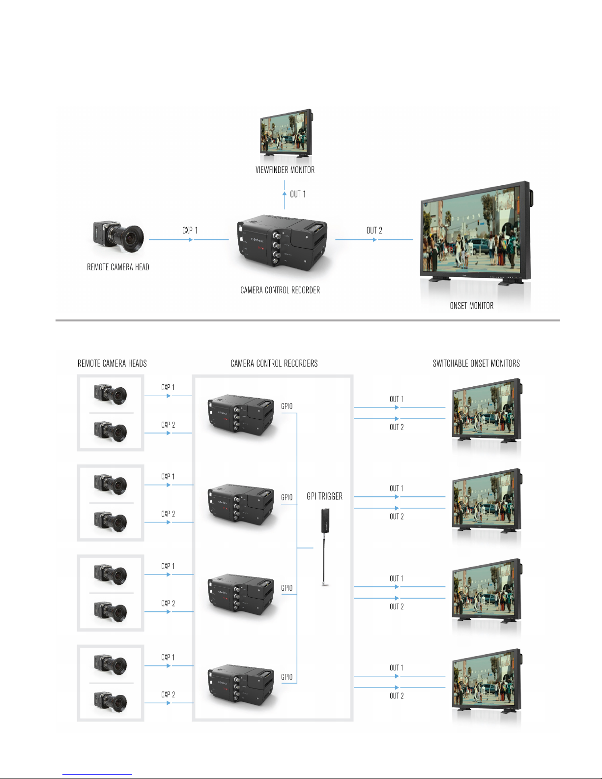
3.7 Connection Examples
3.7.1 Point of View (POV) / Action Camera Setup
3.7.2 Multi-Camera Setup
CODEX USER GUIDE - ACTION CAM 2015.03.03
PAGE 11
Page 12
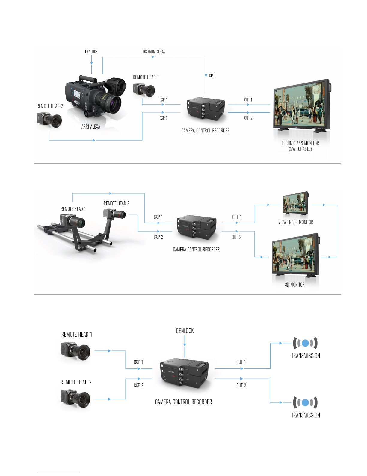
3.7.3 Witness Camera Setup
3.7.4 S3D Camera Setup
3.7.5 Broadcast Setup
CODEX USER GUIDE - ACTION CAM 2015.03.03
PAGE 12
Page 13
3.8 Installing Lenses
Action Cam can be used directly with C-mount lenses (suitable for 2/3” CCD Cameras), or with PL, B4 or EF mount
lenses using the corresponding adaptor available from Codex.
To attach a C-mount lens gently screw it into the standard C-mount thread of the Remote Head.
For further details on PL, B4, and EF lens adaptors contact [email protected].
3.9 Adjusting the Lens Scale Position
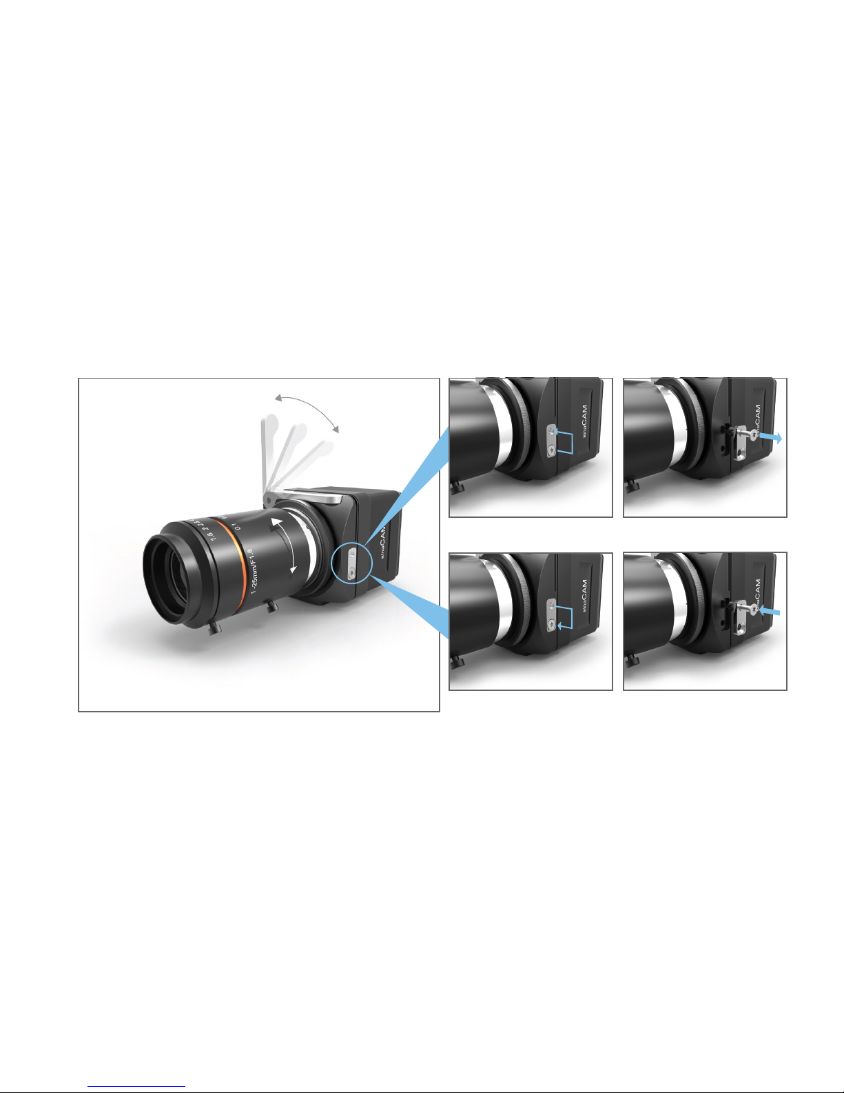
Depending on the camera positioning it may be necessary to for the lens to be tted at a different angle than usual
for the lens scale to remain readable. To provide exibility Action Cam Remote Heads support 6 different positions
for the lens mount, each 60° apart. The lens mount is held in the chosen position by the lens mount lock, with the
lens scale on top by default.
3
7
1
2
4
5
To adjust the position of the lens scale follow these steps:
• Remove the screw from the lens mount lock’s lower screw hole, then partially screw it into the upper one (1).
• Note: The screw will not go all the way in.
• Grip the screw head to pull out the lens mount lock (2).
• Make sure the locking lever is in the open position (3).
• You can now change the position of the lens (4).
• Note: Inside, the lens mount is equipped with 12 holes (each 30° apart) for the lens mount lock.
• Choose one of the valid positions, then reinsert the lens mount lock (5) to x the lens mount in its place.
• Move the screw back into the lower screw hole of the lens mount lock and tighten it (6).
• Then move the locking lever back into the closed position (7).
6
NOTE: After adjusting the lens scale position, adjustment of the ange back distance is also necessary. See
section 3.10 for further details on this procedure.
CODEX USER GUIDE - ACTION CAM 2015.03.03
PAGE 13
Page 14
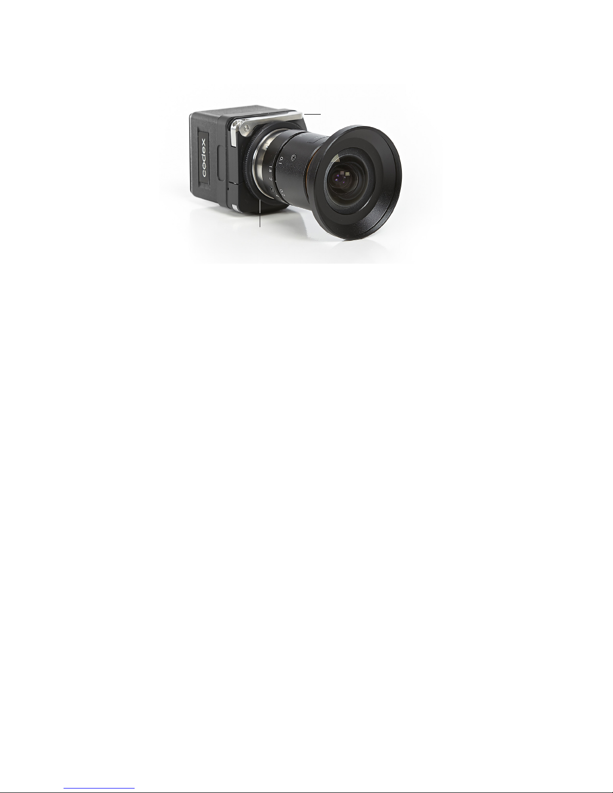
3.10 Adjusting the Flange Back Distance
A
B
If the focus is sharp when zoomed in, but soft when zoomed out, the back focus may need adjustment.
Action Cam Remote Heads allow for easy back focus adjustment by changing the ange back distance between
the rear of the lens and the CCD. This can be done using typical back-focusing techniques, e.g. a test chart or a
back focus collimator. See Appendix A1 and A2 for further details.
Note: Incorrect ange back distance adjustment can result in undesirable focusing issues. Flange back distance
adjustment should only be performed by experts.
To adjust the ange back distance follow these steps:
• Lift up the locking lever (A).
• Turn the adjustment ring (B) until the ange back distance is accurately set (± 1 rotation = ±250 μm):
• To decrease the distance turn to the right (-).
• To increase the distance turn to the left (+).
• Push down the locking lever (A).
• Check the adjustment has been successful with a control measurement.
4. Power On and Off
Once all necessary equipment is connected press the Power button on the top surface of the CCR. When the
CCR has started the Monitor screen will show either running timecode or a message if some settings need to be
checked. The LED ring will light orange if the Capture Drive is formatted and ready for recording, or otherwise blue
if it needs to be formatted.
After power up if the Capture Drive is not formatted, or no Capture Drive is inserted, the CCR cannot enter Monitor
mode and the video hardware will not be fully initialised. At this stage the video output will not be processed
according to the correct settings. Once a formatted Capture Drive is loaded the video hardware will initialise and
the output will appear correctly.
To power off press the Power button on the top surface of the CCR, and then press the Shutdown button under the
Control Panel display. The shutdown process is complete when the Control Panel display switches off.
CODEX USER GUIDE - ACTION CAM 2015.03.03
PAGE 14
Page 15
5. Menu System
5.1 Overview
The Main Menu button provides access to the four main areas of the menu system via the buttons under the
display:
Main Menu Option Description
Monitor Where recording is started and settings for recording can be adjusted.
Play Where playback is controlled and where a shot can be selected for playback.
Setup Where settings for video output, sync, timecode, and shot naming can be adjusted.
Storage Where the Capture Drive can be formatted.
The general operation of the menu system is as follows:
• From any part of the menu system press Main Menu->Monitor to return to the monitor screen, where you must
be to start recording. Then to start recording, if all settings and input signals are correct, press the RECORD
button.
• During recording the only responsive button is STOP which nishes the recording.
• The colour of the LED ring on the Control Panel shows the current mode of the Camera Control Recorder. The
different modes are: Monitor = Orange; Recording = Red; Playing = Green; Pause/Setup = Blue.
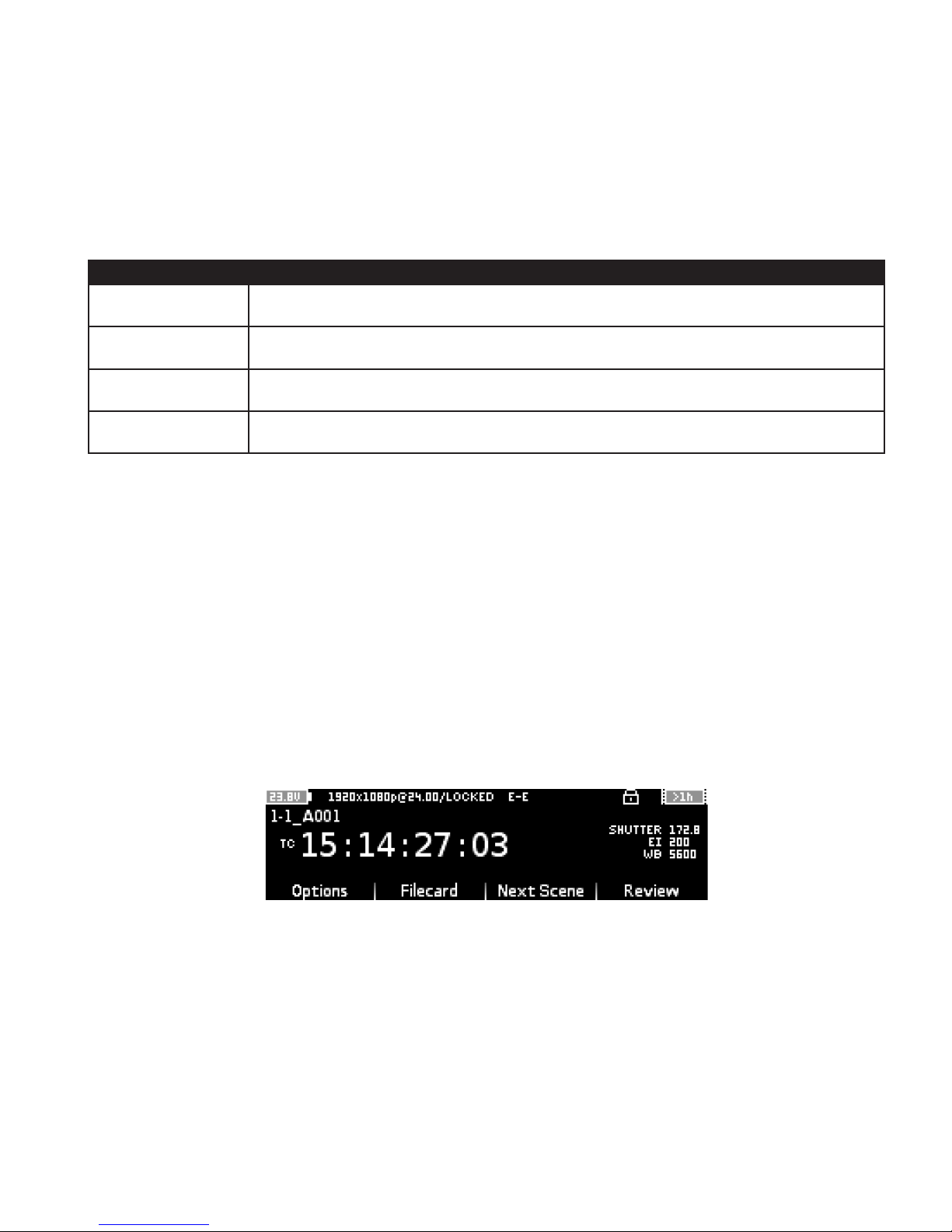
• When the Hold Switch is engaged there will be a padlock symbol at the top of the screen, and none of the
other buttons will respond until the Hold Switch is set to be off. The image below shows the screen with the
padlock symbol:
• In the menus turn the Jog Wheel to move up and down through a list and press the Jog Wheel (SELECT) to
make a selection.
• If there are 3 or less settings (e.g. Monitor->Options->EI: 100, 200, 400) these can be selected from the
buttons under the display. Otherwise press the Jog Wheel (SELECT) to open the list of settings (e.g. Monitor-
>Options->WB).
• Some menus allow text entry but also have presets available, indicated by < and > symbols (e.g. Setup-
>Slate). Press the Next button under the display to move through the presets. Then press Accept to use a
preset, or otherwise Cancel.
CODEX USER GUIDE - ACTION CAM 2015.03.03
PAGE 15
Page 16
• Pressing the Jog Wheel (SELECT) on a text eld will open the text editor. Turning the Jog Wheel moves the
cursor, and Backspace deletes a character. Press Insert to open a row of characters that can be scrolled by
turning the Jog Wheel, and press the Jog Wheel to insert the highlighted character. The Shift button cycles
through Shift, Caps, and Normal case modes. Leave Insert mode by pressing the Cursor button.
• The battery level is always shown in the top left corner of the display.
• The record time remaining is always shown in the top right corner of the display. If this symbol is ashing then
it indicates either that there is less than 5 minutes of record time remaining, or that there is an issue with the
Capture Drive which should be checked from the Storage screen.
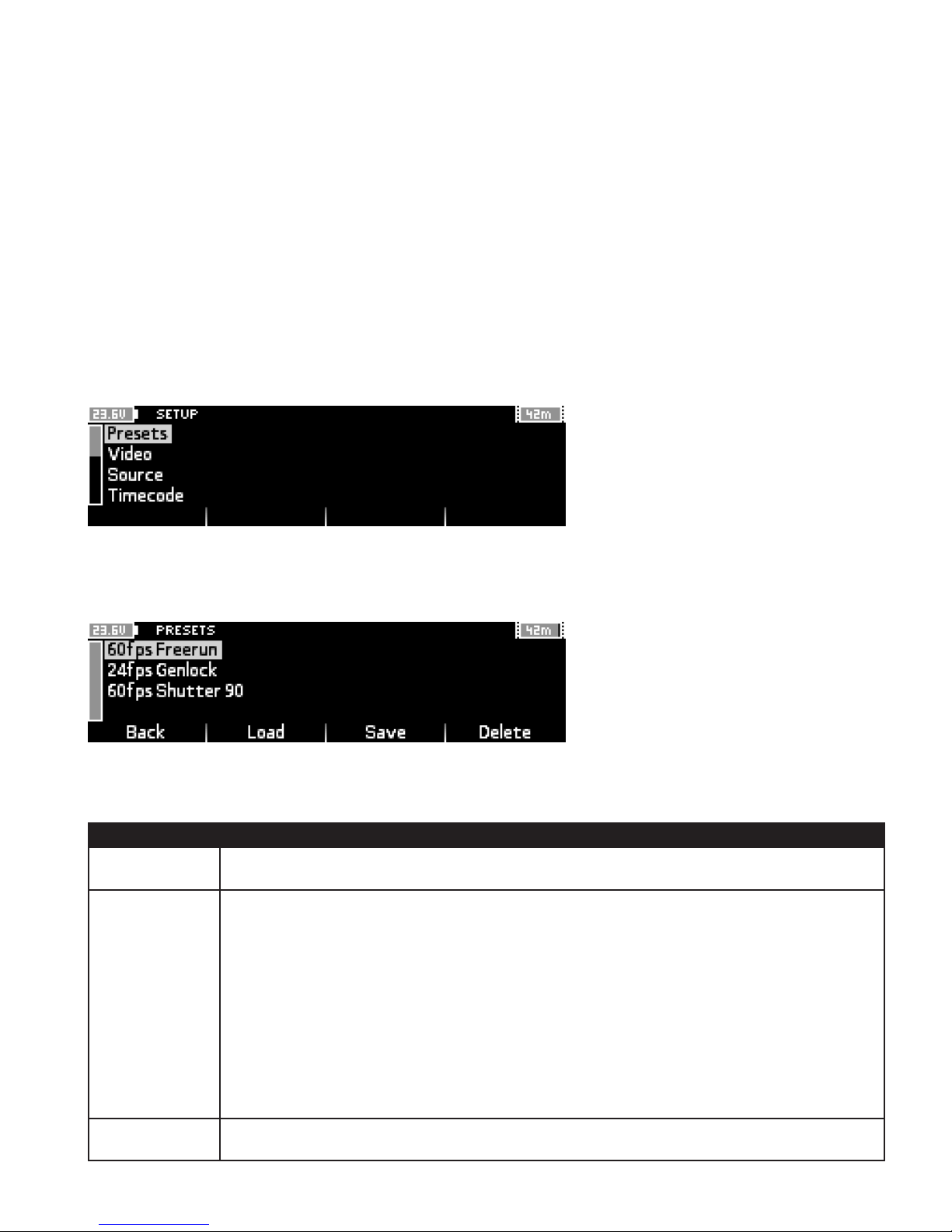
5.2 Setup
Use this menu to access a range of sub-menus for system settings.
5.2.1 Presets
Use this menu to save the current settings as a preset, or to load a previously saved setup.
This makes it fast and easy to move between different setups - for example for different combinations of frame
rate, exposure, and shutter angle. The following options are available:
Option Notes
Load Press to load a previously saved preset.
Save Press to save the current settings as a preset.
By default the presets are named ‘Preset 1’, ‘Preset 2’, etc. but the name of the preset can be
customised when it is saved.
The following settings are saved in the preset:
• Slate settings (Shot and Roll naming)
• Capture settings (EI, WB, Shutter Angle, FPS)
• Video settings
• Timecode settings
Delete Press to delete a previously saved preset from the list.
CODEX USER GUIDE - ACTION CAM 2015.03.03
PAGE 16
Page 17
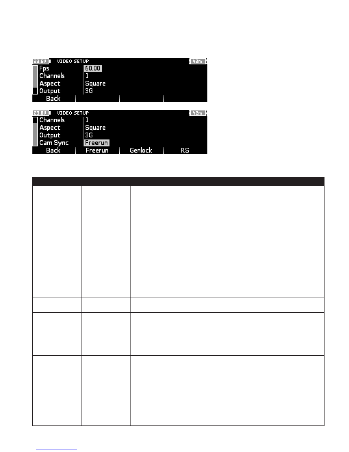
5.2.2 Video
Use this menu to adjust capture and output settings.
The following settings are available:
Setting Options Notes
Fps 23.98
24.00
Sets the video output rate. This must be equal to or higher than the
desired shutter rate.
25.00
29.97
30.00
47.95
If ‘Cam Sync’ is set as ‘Free Run’ or ‘Genlock’ the Remote Head shutter
rate is determined by the Monitor->Filecard->FPS setting. By default this
is Locked to the video output rate.
48.00
50.00
59.94
60.00
Alternative shutter rates (e.g. 12fps, 33.333fps) are set from Monitor>Filecard->FPS. Please refer to section ‘Setting the Frame Rate’ for further
details.
Channels 1
2
Aspect Square
Anamorph x1.3
Output 4:2:2
Default
3G
Duplicated
Remote Head shutter rate is controlled by ‘RS’ input signal if this option is
selected for ‘Cam Sync’.
Note: Changing the shutter rate will alter the exposure level.
Sets the number of Remote Heads to be recorded.
Sets the pixel aspect metadata for the recordings.
This affects the desqueeze applied by the Codex software when
producing deliverables such as ProRes or Avid MXF for editing and
dailies.
Sets the video output mode.
‘4:2:2’ provides a single link 1.5GHz output per Remote Head.
‘Default’ provides a 4:4:4 dual link 1.5GHz output for Remote Head 1.
‘3G’ provides a single link 3GHz output per Remote Head.
‘Duplicated’ provides two single link 1.5GHz outputs for Remote Head 1.
CODEX USER GUIDE - ACTION CAM 2015.03.03
PA GE 17
Page 18
Setting Options Notes
Cam Sync Free Run
Sets the sync source for the Action Cam CCR.
Genlock
RS
‘Free Run’ uses the Action Cam internal clock and is not synchronised to
other devices.
‘Genlock’ synchronizes the video output to the Genlock input signal. If no
Genlock input is connected an error will be shown and recording is not
possible.
‘RS’ synchronizes to the RS output from an ARRI ALEXA to achieve
shutter sync with the camera.
5.2.3 Source
Use this menu to set unique metadata for the Action Cam rig and Remote Heads:
• Source ID: this should be set as a unique ID for each Action Cam, the default is A.
• Channel ID V1: this should be set as a unique ID for Remote Head 1, the default is V1.
• Channel ID V2: this should be set as a unique ID for Remote Head 2, the default is V2.
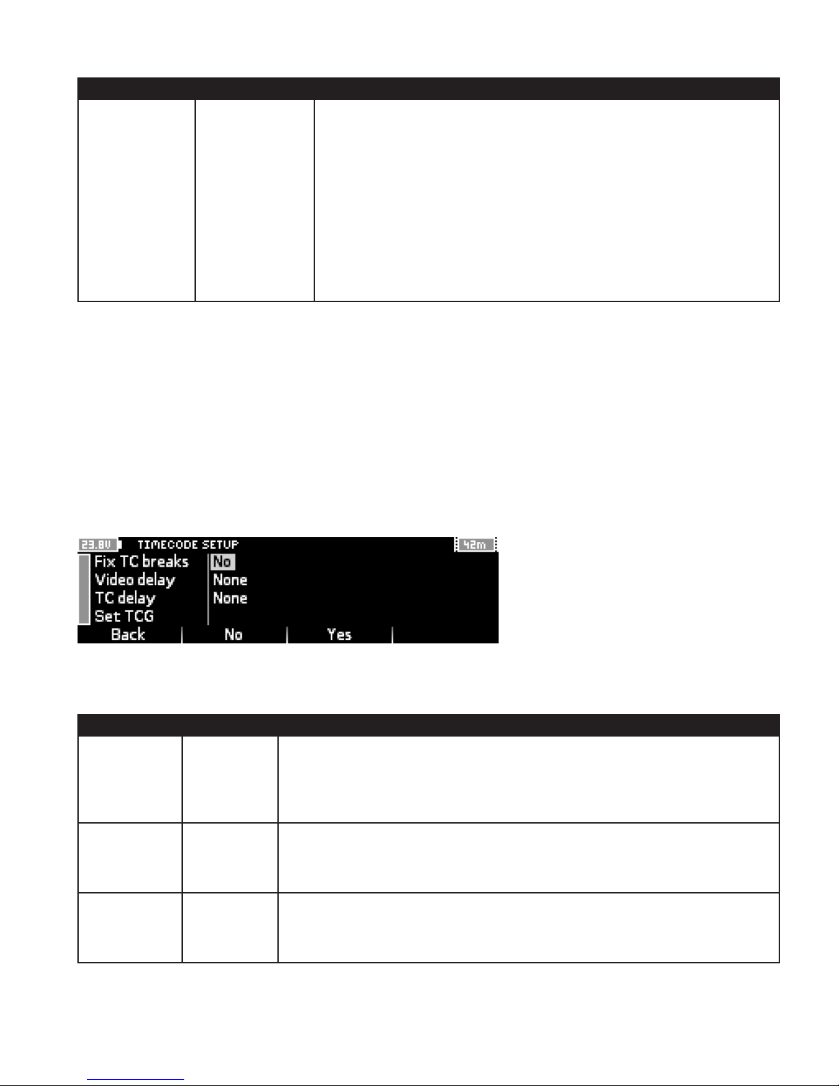
5.2.4 Timecode
Use this menu to adjust timecode settings.
The Action Cam will automatically sync to an external LTC source, or you can set the internal timecode generator
with the Set TCG option. The timecode mode is always continuous run (and not record run).
Setting Options Notes
Fix TC breaks Yes
No
Sets whether the Action Cam will automatically repair timecode if sync is lost
between shutter and timecode input.
Set to Yes if using an external timecode source.
Video delay 1
2
Set to correct for a video delay if a test with a timecode slate shows that video is
delayed with respect to timecode.
3
4
TC delay 1
2
Set to correct for a timecode delay if a test with a timecode slate shows that
timecode is delayed with respect to video.
3
4
CODEX USER GUIDE - ACTION CAM 2015.03.03
PAGE 18
Page 19
Setting Options Notes
Set TCG Set
Sets the internal timecode generator.
Time Of Day
Change
Press ‘Time Of Day’ and then ‘Set’ to set the internal timecode generator to
current time-of-day. To enter another value press ‘Change’ and set the required
timecode followed by ‘Set’.
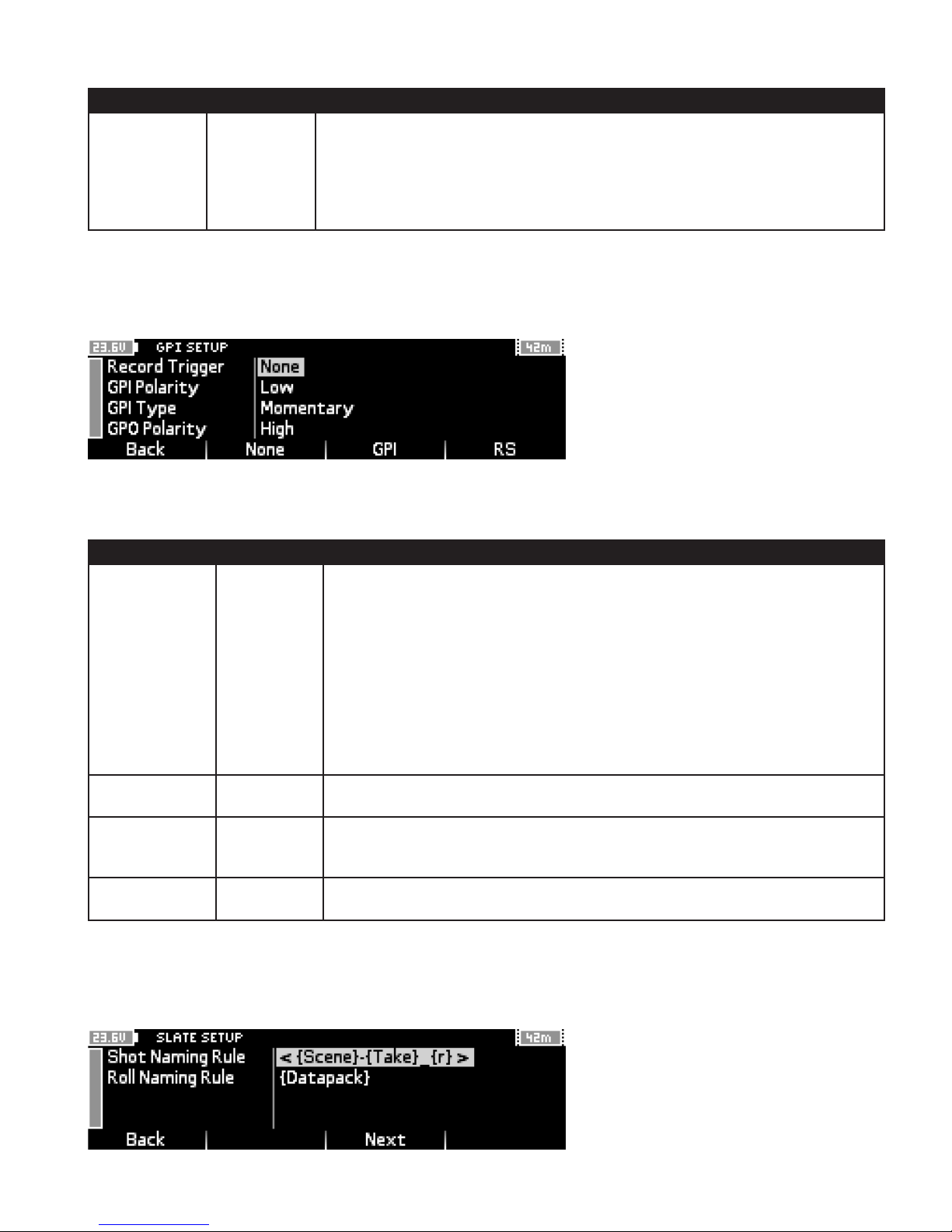
5.2.5 GPI
Use this menu to adjust settings for record triggering.
This may be from an electrical GPI trigger switch or from an RS port on ARRI ALEXA which sends a trigger signal
when the Camera is recording - both of these are connected via the GPIO port on the Action Cam.
Setting Options Notes
Record Trigger None
Sets whether an external source is used to trigger record start/stop.
GPI
RS
Set to ‘None’ to use the RECORD and STOP buttons on the Control Panel.
Set to ‘GPI’ to use an electrical GPI trigger connected to the GPIO port.
Set to ‘RS’ to take the trigger from an ALEXA RS port.
Note: Setup->Video->Cam Sync should also be set to RS to use trigger from
ALEXA RS port.
GPI Polarity Low
Set depending on the conguration of the GPI trigger being used.
High
GPI Type Latching
Momentary
GPO Polarity Low
Set to ‘Latching’ for push-and-release record/stop operation, or ‘Momentary’
for push-and-hold record/stop operation.
Set depending on the conguration of the GPI trigger being used.
High
5.2.6 Slate
Use this menu to set how the shot name and roll name metadata is applied to recordings.
CODEX USER GUIDE - ACTION CAM 2015.03.03
PAGE 19
Page 20
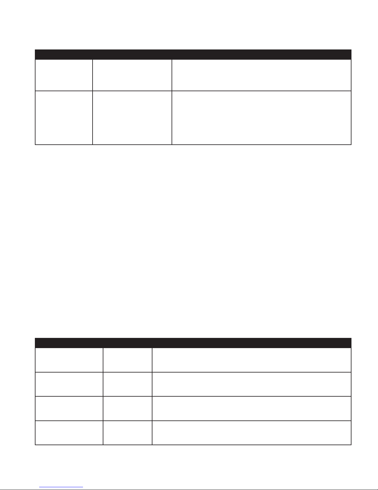
There are a range of presets that can be cycled through using the Next button under the display.
Setting Options Notes
Shot naming rule {Scene}-{Take}_{r}
Sets the structure of metadata used for shot names.
{Scene}-{Take}
{Scene}-{Take}{SourceId}
Scene and Take values are set from Monitor->Filecard.
Roll naming rule {SourceId}{Datapack}
Sets the structure of metadata used for roll names.
{Datapack}
{Datapack} {SourceId}
SourceId is set in Setup->Source->Source ID and should be a
unique ID per Action Cam rig.
Datapack is set by the Roll name given on the Storage screen.
5.2.7 Project
Use this menu to set the following production metadata that will be applied to all recordings:
• Production
• Production Company
• Unit
• Director
• DP
• Location
• Codex Operator
5.2.8 System
Use this menu to check and adjust overall system settings. The top of the display indicates the installed software
version on the Action Cam and the serial number.
The network port settings (IP, Mask, Gateway, DNS) can be congured to facilitate connection from another
computer. This can be used to load LUT les onto the CCR and also to control the Action Cam from another
computer via network.
The other settings available are:
Setting Options Notes
System control Unlocked
Locked
Sets whether the Action Cam can be controlled from a networked
computer (Unlocked) or not (Locked).
Screen contrast 0 - 15 Sets the contrast of the screen. This can be useful in particularly
bright or dark environments.
Control ring bright 0 - 15 Sets the brightness of the Control Panel LED ring. This can be useful
in particularly bright or dark environments.
Rec tally bright 0 - 15 Sets the brightness of the REC light on the side of the CCR. This can
be useful in particularly bright or dark environments.
CODEX USER GUIDE - ACTION CAM 2015.03.03
PAGE 20
Page 21
Setting Options Notes
Shutdown volts Disabled
Default
11V - 24V
Sets the voltage at which the Action Cam will shutdown. ‘Default’
(recommended) is 10V, but this can be Disabled (minimum 8V) or
increased to a higher setting.
Automatic power up Disabled
Enabled
Switch controller RS422 Assigns control of Action Cam from the inbuilt Control Panel to an
CDL server <User Input> Use this setting to specify the IP address for a connected CDL server.
5.2.9 Licence
This menu contains details of the licensed features on an Action Cam. By default these should be HD and Multi.
5.2.10 Date/Time
This menu contains system date and time settings that can be adjusted to be correct for the locale. These settings
are used for the internal timecode generator and also to set the creation time metadata for recordings.
Sets if the Action Cam powers up immediately when a power source
is connected. Use of the ‘Enabled’ setting is recommended.
external Control Panel connected via the RS422 port.
5.3 Monitor
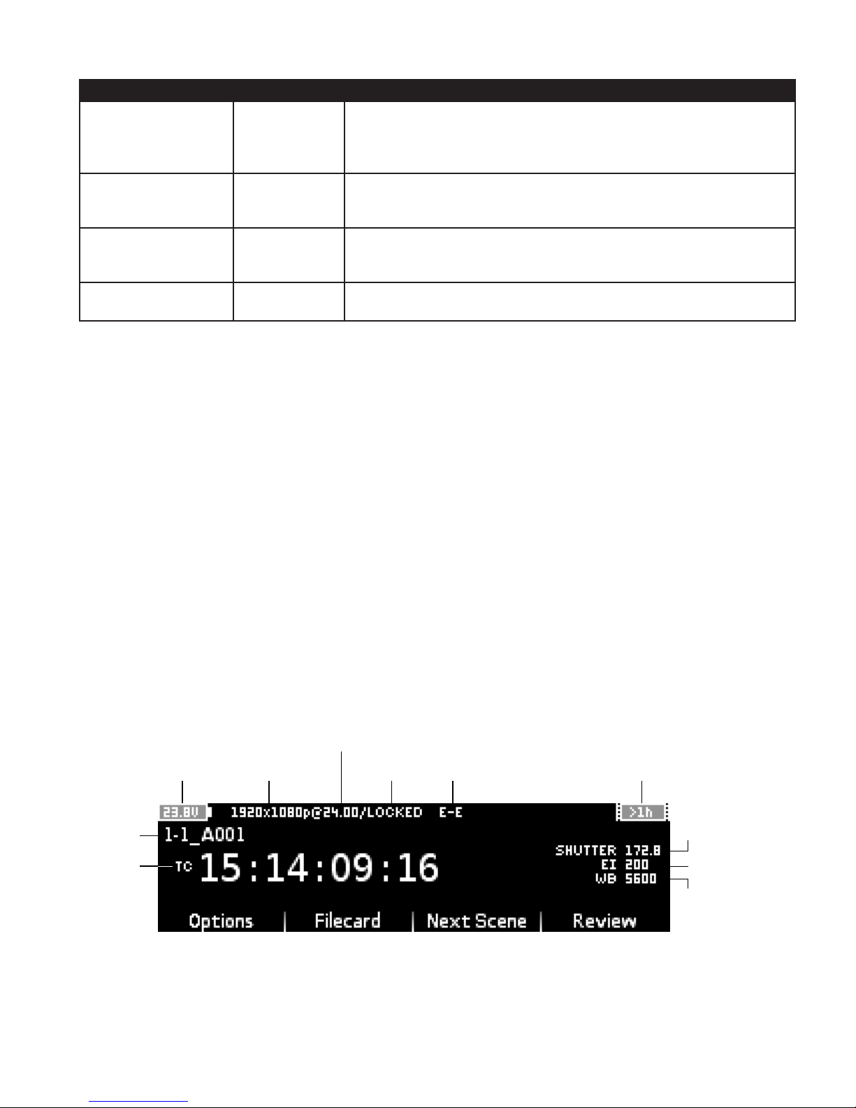
The Action Cam must be on the Monitor screen to start a recording. The Monitor screen shows the current settings
for recording, as well as timecode and any warning/error messages.
5.3.1 Monitor Screen Layout
This image shows the Monitor screen with the shutter rate LOCKED to the video output rate:
VIDEO OUTPUT FRAMERATE
SHUTTER
INPUT VOLTAGE
SHOT NAME
TIMECODE
VIDEO FORMAT MODE
FRAMERATE
RECORD TIME REMAINING
SHUTTER ANGLE
EXPOSURE INDEX
WHITE BALANCE
CODEX USER GUIDE - ACTION CAM 2015.03.03
PAGE 21
Page 22
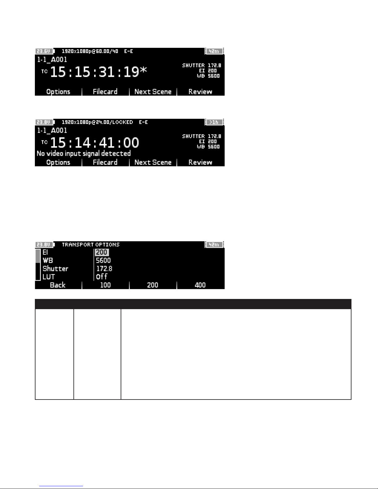
This image shows the Monitor screen when the shutter rate has been set to a custom rate in the Filecard:
If there is a warning or error message it will appear under the timecode display:
Error and warning messages are cleared from the display if their cause is resolved prior to starting a recording. If
a warning or error occurs during recording it will remain on the display until the users moves away from the Monitor
screen to a different menu.
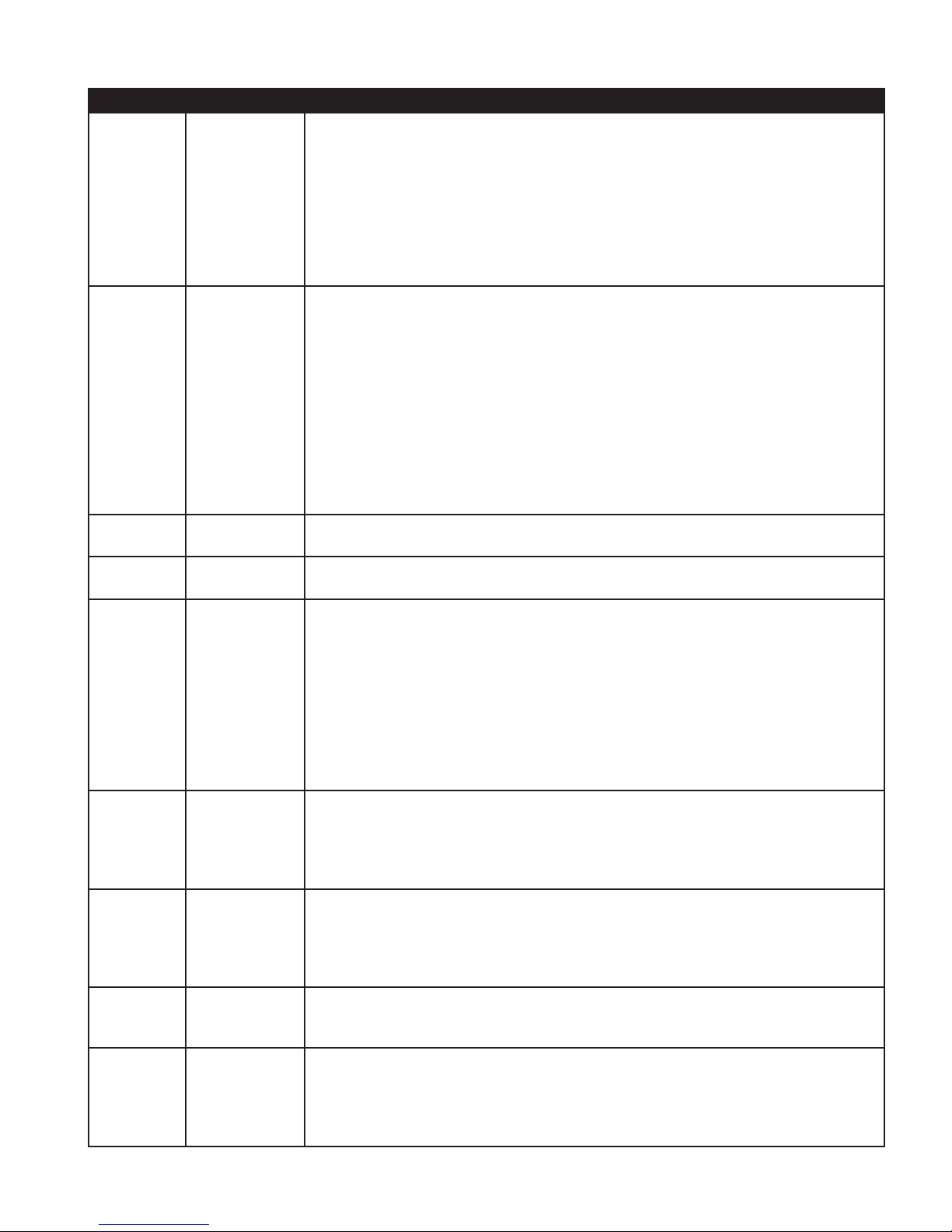
5.3.2 Options
Use this menu to adjust Remote Head settings for capture and output settings for monitoring and playback.
Setting Options Notes
EI 100
Sets the Exposure Index for recordings.
200
400
Changes to this setting affect the live video output.
A setting of 200 does not adjust the gain of the signal. A setting of 100 reduces
the gain, whilst a setting of 400 increases it.
To set a value other than the presets available here use the Filecard.
This sets metadata that does not affect the recorded data, and can be modied
after recording/prior to generating les for post production if necessary.
CODEX USER GUIDE - ACTION CAM 2015.03.03
PAGE 22
Page 23
Setting Options Notes
WB 3200
Sets the White Balance for recordings.
4300
5600
Changes to this setting affect the live video output.
6500
To set a value other than the presets available here use the Filecard.
This sets metadata that does not affect the recorded data, and can be modied
after recording/prior to generating les for post production if necessary.
Shutter 11.2
Sets the shutter angle which determines the exposure time.
22.5
45.0
This can be converted to exposure time as follows:
90.0
135.0
Exposure Time = Shutter Angle / (360 x FPS)
172.8
180.0
Changes to this setting affect the live video output.
270.0
356.0
To set a value other than the presets available here use the Filecard.
Note: Changing the shutter angle will alter the exposure level.
LUT Off
Sets whether a 1D monitoring LUT is applied to the video outputs.
On
LUT Select <User Select> Sets the LUT to be applied to the video output.
TC rate 23.98
Sets the timecode rate for monitoring and the playback rate.
24.00
25.00
This is typically set to the project editing rate.
29.97
30.00
47.95
48.00
50.00
59.94
60.00
TC source TC
Sets the timecode source that is displayed.
AUX
POS
‘TC’ is standard timecode, ‘AUX’ is the auxiliary timecode track, and ‘POS’ is the
timecode position in the current shot starting from 00:00:00:00.
TC type Standard
Sets how the timecode is displayed.
Frames
‘Standard’ is displayed as hh:mm:ss:ff, while ‘Frames’ is a 8-digit number
showing the TC value since midnight or POS value since the start of the shot.
Marks* Set In
Set Out
Set In point and Set Out point for playback, or Clear All playback marks on
current clip.
Clear All
Play loop* Stop
Sets the playback behaviour.
Repeat
Bounce
‘Stop’ will end playback at the last frame of the clip, ‘Repeat’ will play the clip
over and over, and ‘Bounce’ will play the clip forwards and then backwards.
CODEX USER GUIDE - ACTION CAM 2015.03.03
PAGE 23
Page 24
Setting Options Notes
Play range* All
Marks
Sets whether ‘All’ the clip is played, or only the range inside the ‘Marks’. The start
and end of the clip are the In and Out points by default.
*Available in Play mode only.
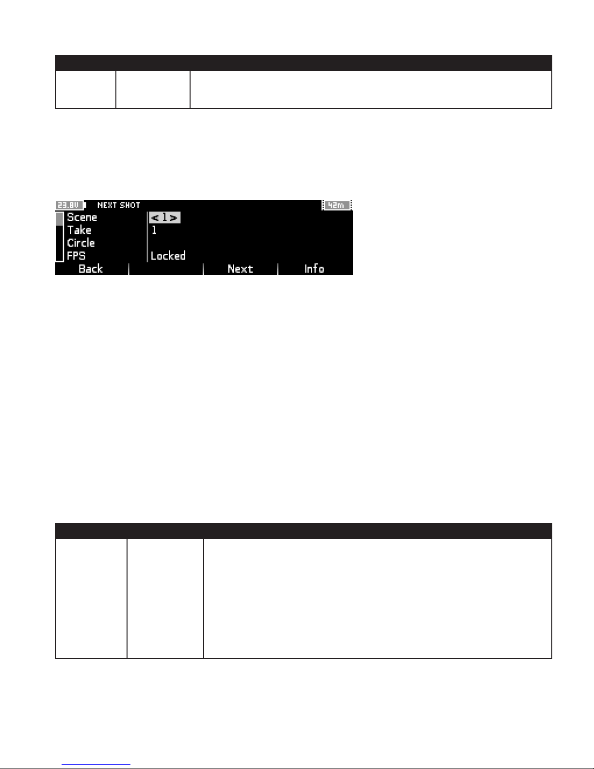
5.3.3 Filecard
Use the Filecard to input metadata for the next shot to be recorded, such as Scene and Take values.
It is also used to enter custom settings for FPS (shutter rate), EI (Exposure Index), WB (White Balance), and Shutter
Angle, before recording.
When the FPS is Locked the camera shutter is running at the same rate as the video outputs. Provided that Setup>Video->Cam Sync is set to ‘Free Run’ then a different FPS can be set in the Filecard.
The full list of settings available in the Filecard is:
• Scene
• Take
• Circle
• Day
• Date
• Comments
• Name
• Roll
• Sound Roll
• Log Note (this information is added automatically when necessary)
Setting Options Notes
EI <User Input>
Press the Jog Wheel to enter a custom setting.
100
200
Press the Next button to move through the preset options.
400
Changes to this setting affect the live video output.
This sets metadata that does not affect the recorded data, and can be
modied after recording/prior to generating les for post production if
necessary.
CODEX USER GUIDE - ACTION CAM 2015.03.03
PAGE 24
Page 25

Setting Options Notes
WB <User Input>
3200
4300
5600
6500
Press the Jog Wheel to enter a custom setting.
Press the Next button to move through the preset options.
Changes to this setting affect the live video output.
This sets metadata that does not affect the recorded data, and can be
modied after recording/prior to generating les for post production if
necessary.
Shutter Angle <User Input>
11.2
22.5
45.0
90.0
135.0
172.8
180.0
270.0
356.0
FPS <User Input>
Locked
23.98
24.00
25.00
29.97
30.00
47.95
48.00
50.00
59.94
60.00
The Filecard is also accessible from the Play->Shots menu to edit metadata after recording.
Press the Jog Wheel to enter a custom setting.
Press the Next button to move through the preset options.
Note: Changing the shutter angle will alter the exposure level.
Sets the Remote Head shutter rate.
The ‘Locked’ setting means Remote Head shutter rate matches Setup->Video-
>Fps setting.
Press the Jog Wheel to enter a custom setting. (If Setup->Video->Cam Sync is
set to ‘RS’ then custom settings are not possible.)
Press the Next button to move through the preset options.
Note: Changing the shutter rate will alter the exposure level.
5.3.4 Next Scene
Use the ‘Next Scene’ button on the Monitor screen to quickly and easily increment the Scene number for the next
recording.
5.3.5 Review
Use the ‘Review’ button on the Monitor screen to play back the last 10 seconds of the previous recording. When
playback nishes the system will return to the Monitor screen.
6. Loading and Unloading Media
To load a Capture Drive lift the door at the front of the CCR. Slide the Capture Drive into the port (with cooling
ridges facing upwards) and push so that the connector is fully mated.
Close the door and the Capture Drive will be loaded. The LED on the Capture Drive will ash blue whilst it loads,
CODEX USER GUIDE - ACTION CAM 2015.03.03
PAGE 25
Page 26
and turn off when it nishes loading.
To unload a Capture Drive lift the door. The Capture Drive will be ejected and the LED will ash blue for a short
time. When it becomes solid blue the Capture Drive can be safely removed.
7. Preparing for Recording
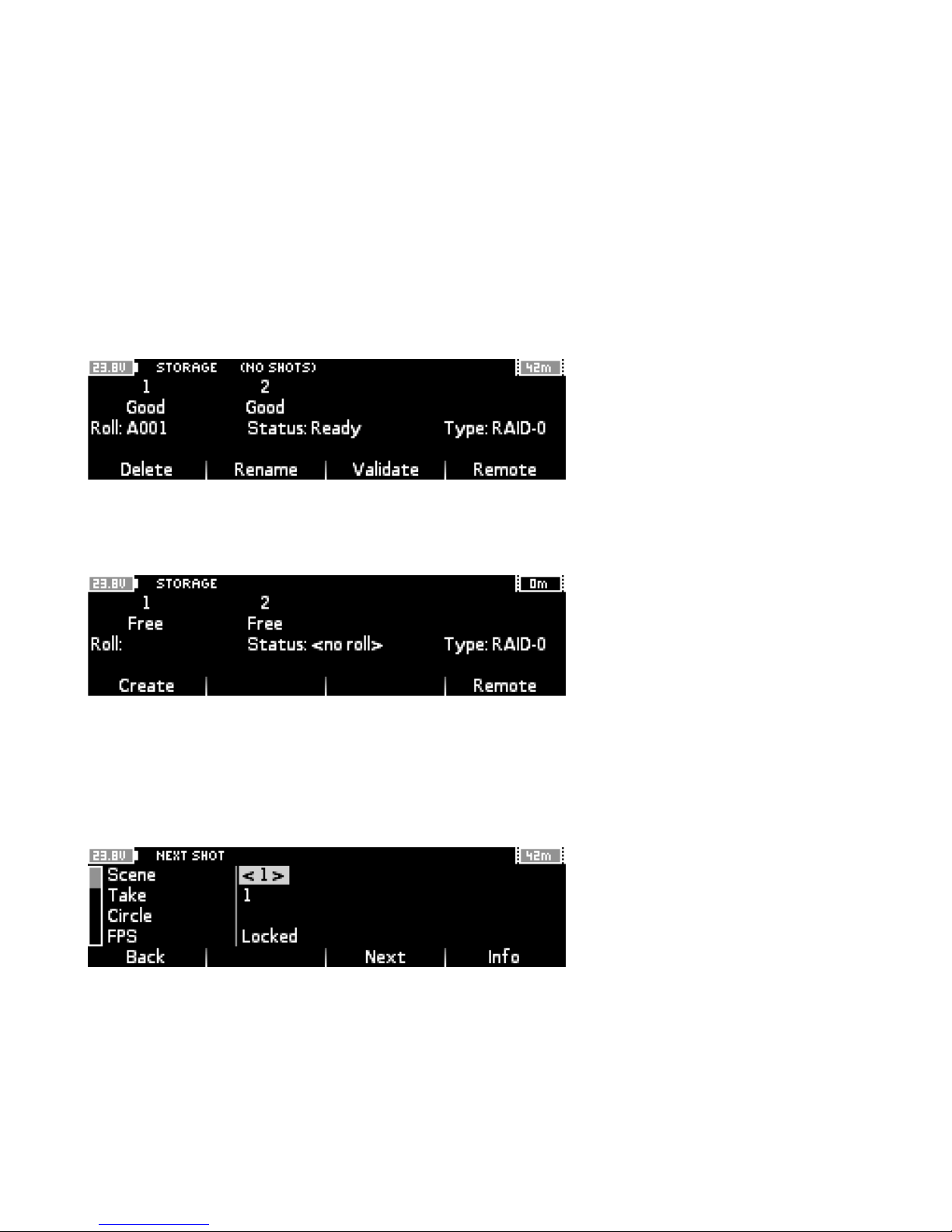
A Capture Drive must be formatted with a Roll before it can be used for recording.
Press Main Menu->Storage to check the status of the Capture Drive. If the Capture Drive is formatted there will be
a Roll number shown and the status will be Ready.
If there is no Roll number press Create and the system will suggest the next Roll number (based on the previous
Roll number that was loaded). Edit the Roll number if required, then press Create again to complete the formatting
process.
8. Setting the Frame Rate
To set the frame rate for recording from the Monitor screen press the Filecard button. Here the FPS (Frames Per
Second) rate of the camera shutter can be changed.
By default the FPS of the shutter is Locked, which means it is the same as the video output frame rate from OUT 1
/ OUT 2.
To change the setting scroll down to FPS. Press the Next button to move through a list of standard frame rates. To
enter a custom frame rate (e.g. 12fps or 33.333 fps) press the Jog Wheel and enter the desired rate.
Note: Setup->Video->Cam Sync must be ‘Free Run’ to allow custom frate rates. If Setup->Video->Cam Sync is set
to ‘RS’ then the shutter rate is determined by the sync signal from the ALEXA and custom settings are not possible.
CODEX USER GUIDE - ACTION CAM 2015.03.03
PAGE 26
Page 27
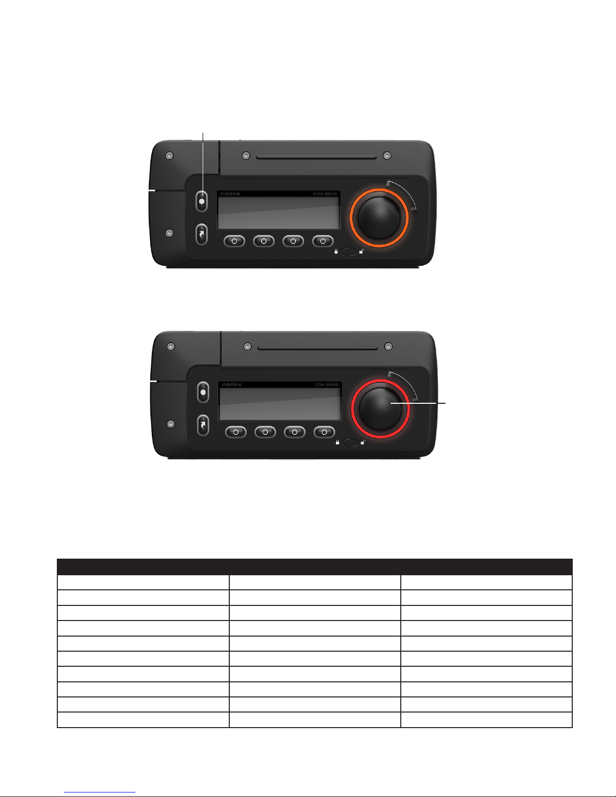
9. Recording
With the Capture Drive formatted and all settings correct, press Main Menu->Monitor. The LED ring should now be
orange and the timecode display should be running.
RECORD
Press RECORD to begin the recording - both the LED ring and the tally light on the other side of the CCR will turn
red.
STOP
Press STOP (centre of Jog Wheel) to end the recording.
If the recording does not start check there is not a warning or error message shown under the timecode display.
In this case please refer to the later section Warning and Error Messages for further information to resolve the
problem.
Frame Rate 1 Camera Record Time 2 Camera Record Time
23.98 107 (minutes) 53
24.00 107 53
25.00 102 51
29.97 84 42
30.00 84 42
47.95 53 26
48.00 53 26
50.00 50 25
59.97 42 21
60.00 42 21
CODEX USER GUIDE - ACTION CAM 2015.03.03
PAGE 27
Page 28
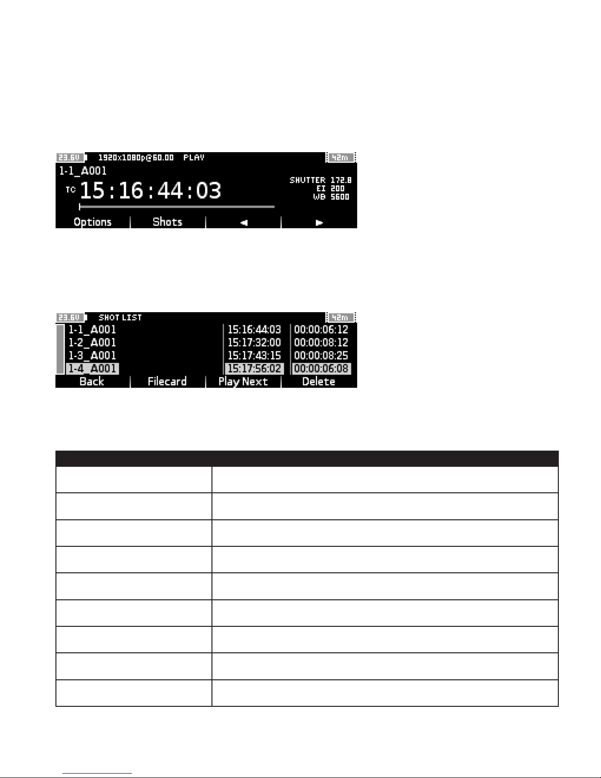
10. Playback
From the Monitor screen press Review to play back the last 10 seconds of the previous recording.
To choose a different shot for playback press Main Menu->Play. The previous recording will be loaded for
playback.
Use the > button to play the shot forwards, and the < button to play the shot backwards. The Jog Wheel can be
used to jog through the shot.
To load another shot press the Shots button, which will bring up the Shot List. Scroll through the list with the Jog
Wheel and press it to select a shot for playback.
11. Remote Head LED Indicators
LED Colour and Behaviour Notes
Off No power
Solid orange System booting
Fast ash green Link detection in progress
Fast ash orange Link detection in progress, resyncing
Solid red Power supply for Remote Head is over current
Slow pulse green Connected to CCR but no data being transferred
Solid green Connected to CCR and data is being transferred
1/2 second pulse red Error during data transfer
Fast ash red System error
CODEX USER GUIDE - ACTION CAM 2015.03.03
PAGE 28
Page 29
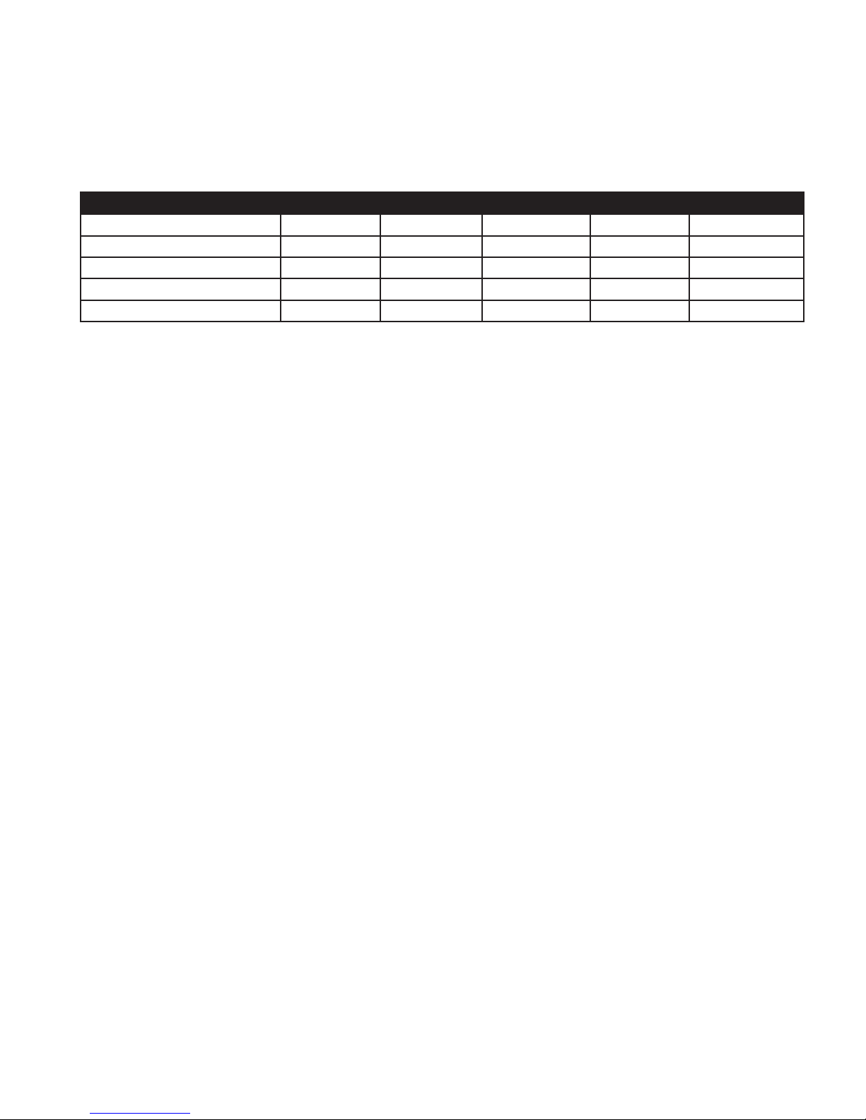
12. Recommended Settings
The table below covers the recommended input and output settings for a range of shooting setups the Action Cam
can be used on:
Setting Action Cam Multi Cam Witness Cam S3D Cam Broadcast Cam
Setup->Video->Fps Your choice Your choice Your choice Your choice Your choice
Setup->Video->Channels 1 2 2 2 2
Setup->Video->Output Duplicated 4:2:2 4:2:2 4:2:2 4:2:2
Setup->Video->Cam Sync Free Run Genlock RS Free Run Genlock
Setup->GPI->Record Trigger None GPI RS None None
For the Setup->Slate settings the following preset options are sensible defaults:
Shot Naming Rule: {Scene}-{Take}_{r}
Roll Naming Rule: {SourceId}{Datapack}
CODEX USER GUIDE - ACTION CAM 2015.03.03
PAGE 29
Page 30
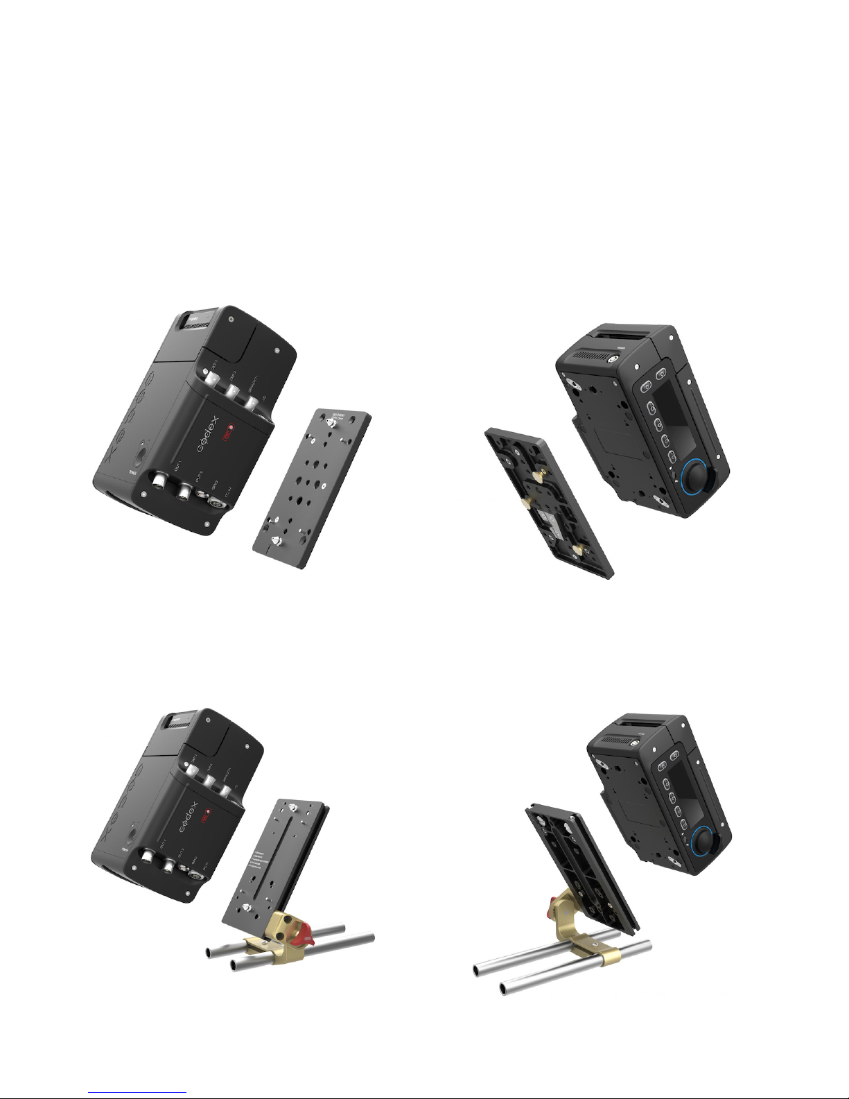
13. Mounting Options
The Action Cam CCR has an integrated quick release mounting system built into the base. This can be used with
a mount plate in a range of congurations to provide exible solutions for mounting on its own rig or in combination
with other camera systems such as the ARRI ALEXA.
13.1 Cheeseplate Mount
The cheeseplate mount provides a range of mounting options, including compatibility with Anton Bauer and IDX
battery mounts. Standard mount threads allow for mounting in a range of custom congurations.
13.2 Vocas Mount
With the Vocas mount the CCR can be securely mounted to 15mm rails with quick and easy angle adjustment
.
CODEX USER GUIDE - ACTION CAM 2015.03.03
PAGE 30
Page 31
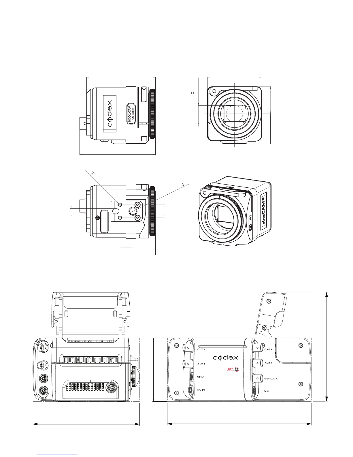
14. Dimensions
53
41.8
14.1 Remote Head Dimensions
M3 3 (2x)
12.8
image circle
23.2 20.9
58.2
+0.02
+0.032
4
10
13.2
17.2
14.2 Camera Control Recorder Dimensions
1/4’’ - 20 UNC 5.5
10
142.3 mm
RS422
139 mm
CODEX USER GUIDE - ACTION CAM 2015.03.03
82.8 mm
187.6 mm
PAGE 31
Page 32
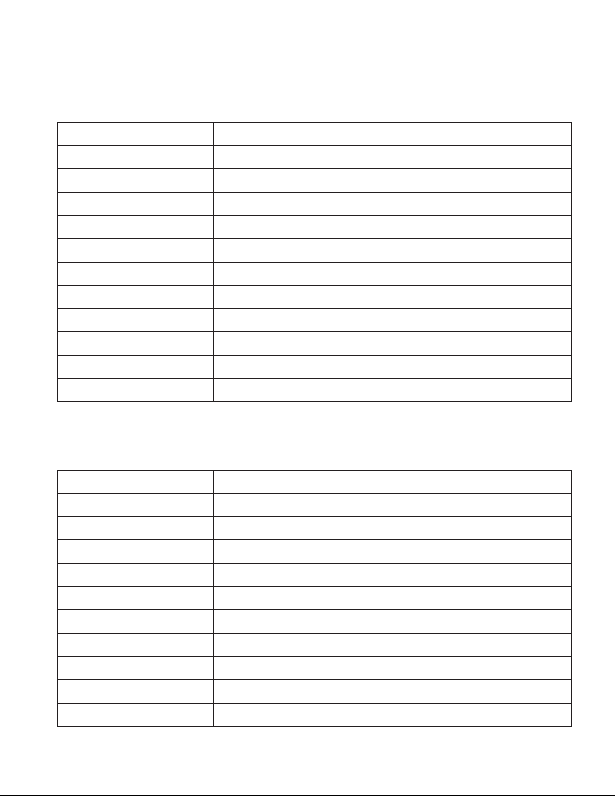
15. Technical Specifications
15.1 Remote Head Specification
Image Sensor 2/3” Single Chip Kodak CCD Sensor (RGB) 2004×1144 Pixels, Progressive Scan
Electronic Shutter Type Global
Sensitivity 2000Lux @ f8.0 / 0dB Gain (100% video out) 160Lux @ f2.2 / 0dB Gain (100% video out)
Resolution 1920×1080 Pixels (5.5 μm pixel size)
Active Image Area 10.56mm x 5.94mm (12.1mm diagonal, 2/3” optical format)
Dynamic Range 13.5 f-stops
Signal/Noise Ratio 64 dB @ 0 dB Gain
Interface CoaXPress, 75 Ω BNC Cable
Max. Cable Lengths 80 m (260 ft) with Standard BNC Cable
Lens Mount C-mount with Flange Back Distance adjustment
Power Consumption 4.6 W max.
Operating Temperature Range 0 to 45 °C (32 to 113 °F)
15.2 Camera Control Recorder Specification
White Balance Modes 3200 K, 4300 K, 5600 K, 6500 K, User Input
Exposure Control 100, 200, 400 ASA, User Input
Gamma Action Cam Log
Electronic Shutter 11.2, 22.5, 45.0, 90.0, 135.0, 172.8, 180.0, 270.0, 356.0°
Remote Head Connections CoaXPress (via 75 Ω BNC Cable)
HD-SDI Output Formats Up to 2 x HD-SDI (SMPTE 292M, 372M), 1920x1080, 10-bit 4:2:2 or 4:4:4
Recording Formats 12-bit Bayer, 1920x1080, 23.98, 24, 25, 29.97, 30, 47.95, 48, 50, 59.94, 60
Synchronization Internal, ALEXA RS, or GenLock to Tri-Level Sync or Black Burst
Network Ports 1Gb Ethernet
Power Consumption 30 W max (including 2 Remote Heads)
Operating Temperature Range 0 to 45 °C (32 to 113 °F)
CODEX USER GUIDE - ACTION CAM 2015.03.03
PAGE 32
Page 33
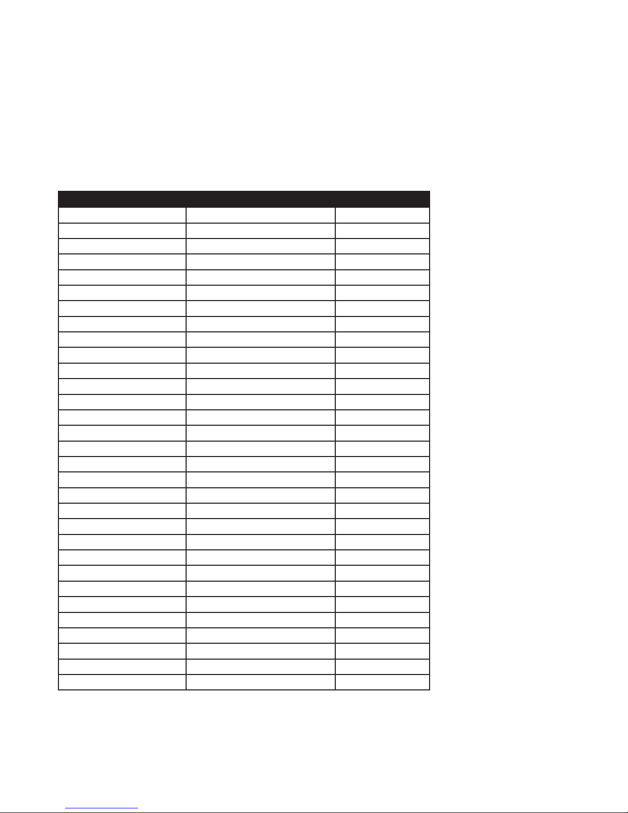
16. Colour Management
16.1 Video Output Code Distribution Chart
The following table details how the Action Cam Log Curve distributes 10-bit SMPTE video code values across the
available latitude in Stops from the camera.
Stop 10-bit SMPTE video code (v) Codes / half stop
2.0 (800 ASA clip point) 1016 (MAX) 50
1.5 966 50
1.0 (400 ASA clip point) 916 50
0.5 866 50
0.0 (200 ASA clip point) 816 50
-0.5 766 50
-1.0 716 50
-1.5 666 49
-2.0 617 49
-2.5 568 48
-3.0 520 48
-3.5 472 46
-4.0 426 46
-4.5 380 43
-5.0 337 42
-5.5 295 38
-6.0 257 35
-6.5 222 32
-7.0 190 27
-7.5 163 23
-8.0 140 18
-8.5 122 15
-9.0 107 11
-9.5 96 9
-10.0 87 6
-10.5 81 5
-11.0 76 3
-11.5 73 3
-12.0 70 2
-12.5 68 1
-13.0 67 1
CODEX USER GUIDE - ACTION CAM 2015.03.03
PAGE 33
Page 34
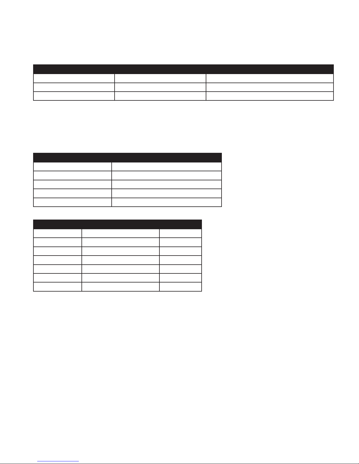
16.2 “Cineon” Equivalence
The Action Cam log encoding is based on classic Cineon, but with different parameters:
Parameter Cineon Log Value Action Cam Log Value
Black 95 64
White 685 560
FilmNegGamma 0.6 0.667443421
16.3 Special Values
The following values are provided as common reference points:
10-bit SMPTE code value Linear value, t (to six decimal places)
4 -0.011437
64 0.000000
560 1.000000
940 14.192376
1016 24.000000
Linear value, t 10-bit SMPTE code value Waveform %
0.00 64 0
0.18 332 31
0.90 545 55
1.00 560 57
6.00 816 86
12.00 916 97
24.00 1016 109
CODEX USER GUIDE - ACTION CAM 2015.03.03
PAGE 34
Page 35
16.4 Use of Exposure Index
The native ASA of Action Cam is 200, with a clipping point at 600% video level. The Action Cam Log Curve can
represent values up to 2400%.
The standard Exposure Index settings available in the camera are 100, 200, and 400.
For a 10-bit SMPTE video code value x, to convert to a normalised signal level v:
v = (x-64)/876
The normalised signal level must be multiplied by a constant to get a linear value t:
t = normalisedSignalLevel * 6 * (exposureIndex/200)
16.5 Log To Linear Conversion
The following
t = (pow(10, (v - a) / b) - c) / (1 - c)
16.6 Linear To Log Conversion
v = a + b * log10( c + t*(1 - c) )
16.7 Conversion Variables
The following variables are used when processing the output of Action Cam:
Variable Value
a 0.566210
b 0.380962
c 0.032639
CODEX USER GUIDE - ACTION CAM 2015.03.03
PAGE 35
Page 36

17. Warning and Error Messages
Warning/Error Notes Action
No video input signal detected No valid input signal detected on
CXP1 by the CCR. The signal could
be absent or too weak (or not from
an Action Cam Remote Head).
Check cabling between the Remote
Head and the CCR.
No video input signal 2 detected No valid input signal detected on
CXP2 by the CCR. The signal could
be absent or too weak (or not from
an Action Cam Remote Head).
Video CRC error An error has been detected on
the input signal. This may result
in visible errors on the recorded
image.
Video frame dropped There has been loss of input signal
during recording, or a failure writing
data to the Capture Drive.
Timecode break The timecode and shutters have lost
sync, which may result in duplicate/
missing timecode values in the shot.
Roll is full There is no more space on the
Capture Drive.
Check cabling between the Remote
Head and the CCR.
Check cabling. It could be
damaged, too long, or suffering
interference from lighting etc.
Check cabling. If this happens
from one Remote Head it may be a
cable issue. If it happens from two
Remote Heads it may be a Capture
Drive issue.
Check video and timecode source
genlock.
Load a Capture Drive which has
storage space remaining.
CODEX USER GUIDE - ACTION CAM 2015.03.03
PAGE 36
Page 37

18. Connector Pin Outs
Connector Pins
LTC - 5 pin 0B Lemo socket 1 Ground
2 LTC IN +
3 LTC IN —
4 LTC OUT —
5 LTC OUT +
For unbalanced input, use ‘LTC IN +’ and connect ‘LTC IN -’ to ground (Pin
1).
GPIO - 7 pin 0B Lemo socket 1 Reserved for RS232 RX - DO NOT CONNECT
2 Reserved for RS232 TX - DO NOT CONNECT
3 Ground
4 GPI IN
5 GPI OUT
6 Reserved - DO NOT CONNECT
7 Reserved - DO NOT CONNECT
DC IN - 5 pin 1B Lemo socket 1 Battery V— (0V)
2 IDX SCL (IDX digital clock)
3 IDX SDA (IDX digital data)
4 AB DATA (Anton/Bauer coms)
5 Battery V+ (12-28V DC)
RS422 - 6 pin 0B Lemo socket For connection to Codex Control Panel CDX-P065 only.
CODEX USER GUIDE - ACTION CAM 2015.03.03
PAGE 37
Page 38

APPENDIX
A1. Flange Back Distance and Back Focus Adjustment
Flange Back Distance is the distance between the lens mount ange and the camera sensor (or lm) plane. Back Focus
Adjustment is a feature of the specic lens being used, and adjusts the distance between the rear element of the lens
and the camera sensor (or lm) plane. For accurate and consistent focus it is crucial to have both of these distances
correctly aligned.
When they are calibrated properly, the distance markings on the lenses are exact but when they are misaligned, even
by a few microns, the distance markings on the lens can be wildly off and completely unreliable, with the potential to
cause major focus issues. This is equally essential when measuring by distance to pull focus.
With the Codex Action Cam, you can adjust ange back distance for any attached lens – the procedure is outlined in
Section 3.10 of this guide. Once a lens is mounted that has it’s own back focus adjustment, it is critical to adjust this as
well for optimum focus.
Note: The correct ange back distance for one lens may not be suitable for a different lens. Therefore after changing
lenses it is possible for an image that is sharp when zoomed in to be soft when zoomed out. In this case the ange back
distance (and lens back focus adjustment where available) should be checked and adjusted again as necessary.
As the ange back distance is critical to achieve the best shooting results it should be done -
• During camera prep when assembling the equipment at the start of the production.
• Before each shooting day.
• After every lens change.
• After signicant temperature changes of the equipment, for example when moving from indoors to outdoors.
Before starting the adjustment, connect the Remote Head to the Camera Control Recorder (CCR) and connect a high
resolution video display to the video output - see Section 2.2 of this guide for connector details and Section 5.2.2 for
video settings.
Put the video display in a “high contrast” setting and mount the camera on a tripod.
Position the recommended Test Chart (Appendix A2. Figure 1.) at least 2 to 3 metres (8 to 10 feet) from the camera.
Alternatively follow the rule of thumb “lens focal length in mm x 25 = minimum distance in millimeters to the pattern”.
Otherwise, position the chart as far as possible with good pattern visibility. Follow the procedure below to set ange
back distance:
1. Set the iris to manual.
2. Set the zoom control to manual.
3. Open the iris to its widest aperture. If the illumination on the test chart is too bright for the open iris, reduce
the light, use ND ltering or move the chart to a darker area.
4. Set the Shutter to 356.0 (max open) as described in Section 5.3.2.
5. Switch off any macro feature in your lens.
6. Turn the zoom barrel to extreme telephoto.
7. Focus on the center of the chart.
8. Set the zoom to wide angle .
9. Loosen the back focus locking lever (A) on the Remote Head. (Appendix A2. Figure 2.)
10. Slowly adjust the ange back adjustment ring (B) on the Remote Head (Appendix A2. Figure 2.) for the sharpest
focus, using the “pop-out or target cross” effect of the test chart.
11. Repeat steps 6 through 10 until focus is consistently sharp.
12. When satised, tighten the locking lever to secure the back focus ring.
Note: The hexscrew on the side of the Action Cam is not an adjustment for focus. It releases the “Lens mount lock”
which can be used to alter / rotate the mounting position of the Lens relative to the camera body in 12 different positions
so that the Lens scale remains readable. See Section 3.9 for details.
CODEX USER GUIDE - ACTION CAM 2015.03.03
PAGE 38
Page 39
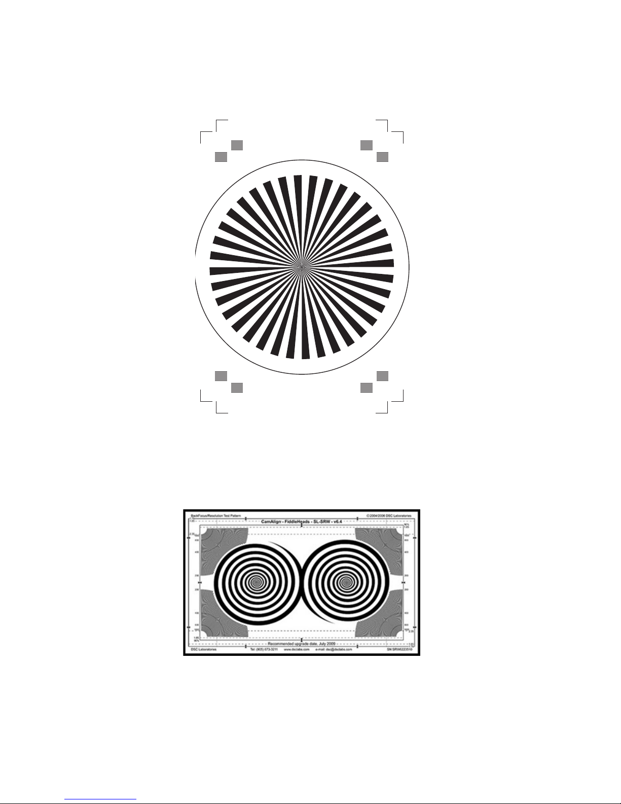
A2. Recommended Test Charts
Figure 1.
Siemens Star Chart
A printable eps file is available for download at http://www.codexdigital.com/products/action-cam
DSC FH SW FiddleHeads Test Chart
http://dsclabs.com/shop/resolution-focus/fiddleheads-with-resolution/
Note: a usable chart should be printed at least A3 size or larger
CODEX USER GUIDE - ACTION CAM 2015.03.03
PAGE 39
Page 40
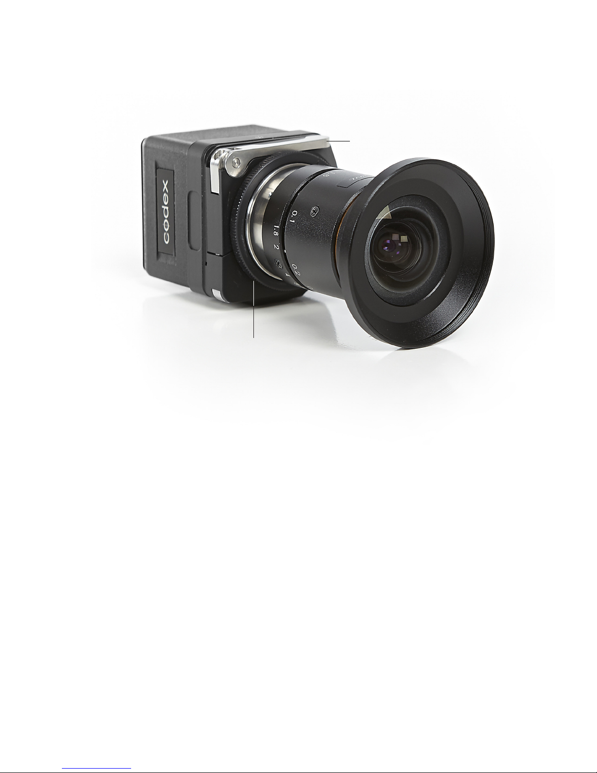
Figure 2.
A
B
CODEX USER GUIDE - ACTION CAM 2015.03.03
PAGE 40
Page 41

Notes
CODE X 60 POL AND ST REET LON DON ENG LAN D W1F 7NT UK TEL +44 207 292 6 918 CODEXD IGITAL.C OM INFO @COD EXDI GITAL.CO M
Codex reserve the right to alter the specication at any time and without prior notice. © Copyright Codex September 2014.
CODEX USER GUIDE - ACTION CAM 2015.03.03
PAGE 41
 Loading...