

Page 1

CODE SOFT
s4 Label printer user’s manual
Version: 1.1
Page 2

Ver:1.1
s4 series user’s manual
I
Table of contents
1. Introduction............................................................................................................1
1.1 In the box......................................................................................................1
1.2 Printer Features..........................................................................................2
1.2.1 Front view...........................................................................................2
1.2.2 Rear view............................................................................................2
1.2.3 Interior view........................................................................................3
2. Getting start...........................................................................................................4
2.1 Loading the ribbon.....................................................................................4
2.2 Loading the media......................................................................................8
2.3 Connecting interfaces.............................................................................12
2.3.1 Centronics port (Parallel port).......................................................12
2.3.2 RS-232 port (Serial port)................................................................12
2.3.3 USB Slave........................................................................................13
2.3.4 Ethernet (Option).............................................................................13
2.4 Power on the printer................................................................................14
2.5 Control panel.............................................................................................14
3. Printer options.....................................................................................................17
3.1 Peeler installation.....................................................................................17
3.2 Cutter installation.....................................................................................24
4. LCD screen icons...............................................................................................30
4.1 LCD screen information .........................................................................30
4.2 Graphic symbol on LCD screen...........................................................31
5. Configuration.......................................................................................................32
5.1 Menu structure..........................................................................................32
5.2 Parameters setup.....................................................................................35
5.2.1 User Setup .......................................................................................35
5.2.2 Communication setup.....................................................................35
5.2.3 Print Setup........................................................................................37
5.2.4 Test....................................................................................................39
5.2.5 Memory.............................................................................................39
5.2.6 Form..................................................................................................39
5.2.7 Warning message...........................................................................40
5.2.8 Printer status....................................................................................41
6. Troubleshooting..................................................................................................42
6.1 LCD error message..................................................................................42
Page 3

Ver:1.1
s4 series user’s manual
II
7. Specifications......................................................................................................43
7.1 General specifications............................................................................43
7.2 Universal Serial Bus (USB) port pin assignment.............................45
7.3 Serial port pin assignment.....................................................................46
7.4 Ethernet module port pin assignment................................................46
Page 4

Ver:1.1
s4 series user’s manual
III
About this user ’s manual
This user’s manual is described with a large quantity of illustrations, let the
users understand, step by step, how to work this printer to its best. This
manual includes also the troubleshooting section which could provide a
pre-way to eliminate or find out the troubles, without the help of technician. If
users still cannot banish the troubles from the printer, please contact directly
the distributors.
Page 5

Page 6
Ver:1.1
s4 series user’s manual
1
1. Introduction
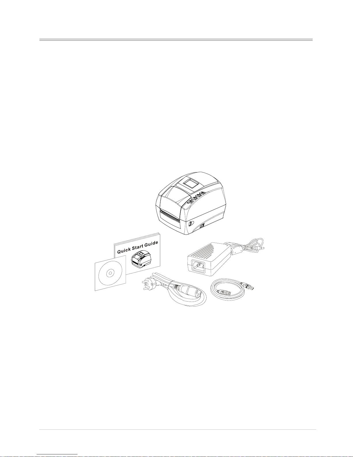
1.1 In the box
After unpacking, please inspect carefully and make sure that you receive all
the necessary parts as below:
Printer
Power supply
Power Cord (varies by country)
Software CD ROM
Quick start guide
USB cable
If any parts are missing, please contact the service department of your
distributor.
Save the carton and all packing materials in case you need to reship back.
Page 7
Ver:1.1
s4 series user’s manual
2
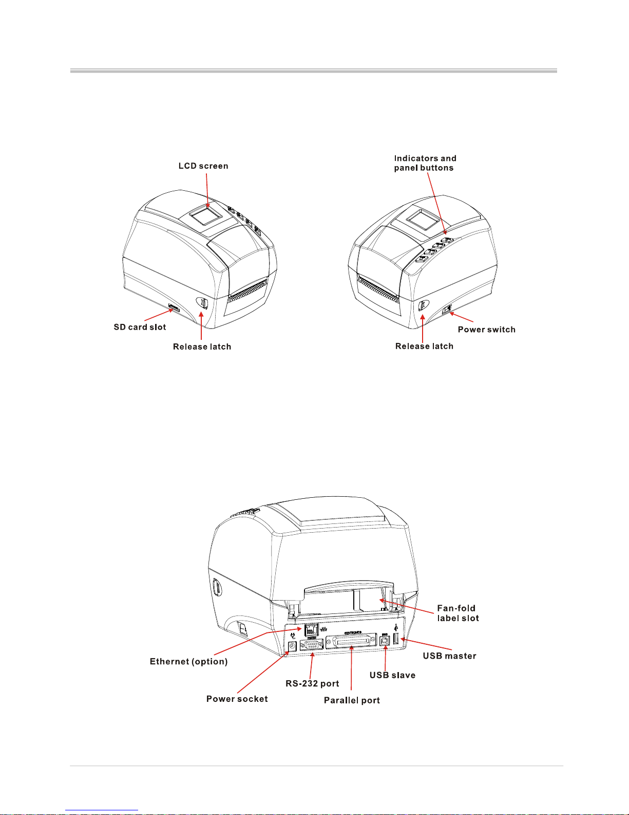
1.2 Printer Features
1.2.1 Front view
1.2.2 Rear view
Page 8
Ver:1.1
s4 series user’s manual
3
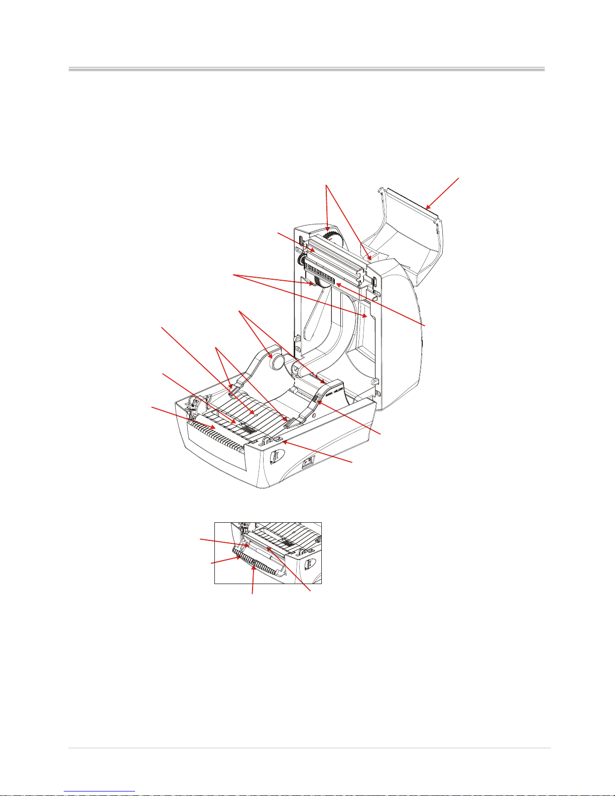
1.2.3 Interior view
Media roll holder
Media guide
Adjustable media
gap sensor
Platen roller
Cover-up sensor
Media holder
lock latch
Supply spindles
Printhead
Array sensors
Take up spindles
Tear-o
ff
blad
e
Dispenser (option)
Peel-off roller
Peeler sensor
Peeler bar
Dispenser cover
Media sensor
Page 9
Ver:1.1
s4 series user’s manual
4
2. Getting start
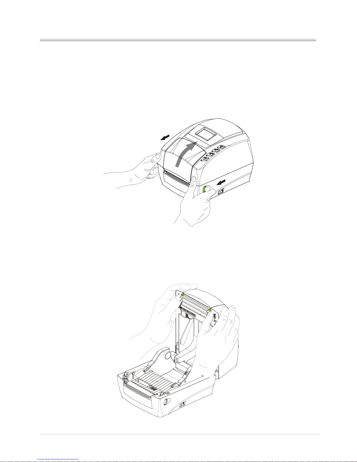
2.1 Loading the ribbon
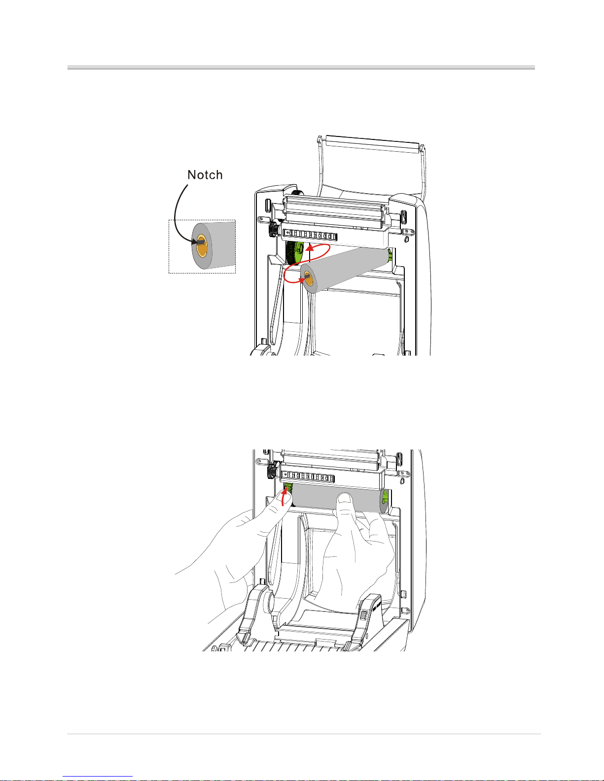
1. Pulling the release latches on two sides toward the front of printer to open
the printer cover.
2. Open the ribbon cover by pushing the ribs (as shown in green) of ribbon
cover. Do not open the ribbon cover by pushing the cover edge which
installed the blade to tear off the label. It might hurt your hands if you push it
hardly.
Page 10
Ver:1.1
s4 series user’s manual
5
3. Insert the ribbon roll to the supply spindle.
4. Rotate the supply hub until the notches align and lock in to the left side of
supply hub.
Page 11
Ver:1.1
s4 series user’s manual
6
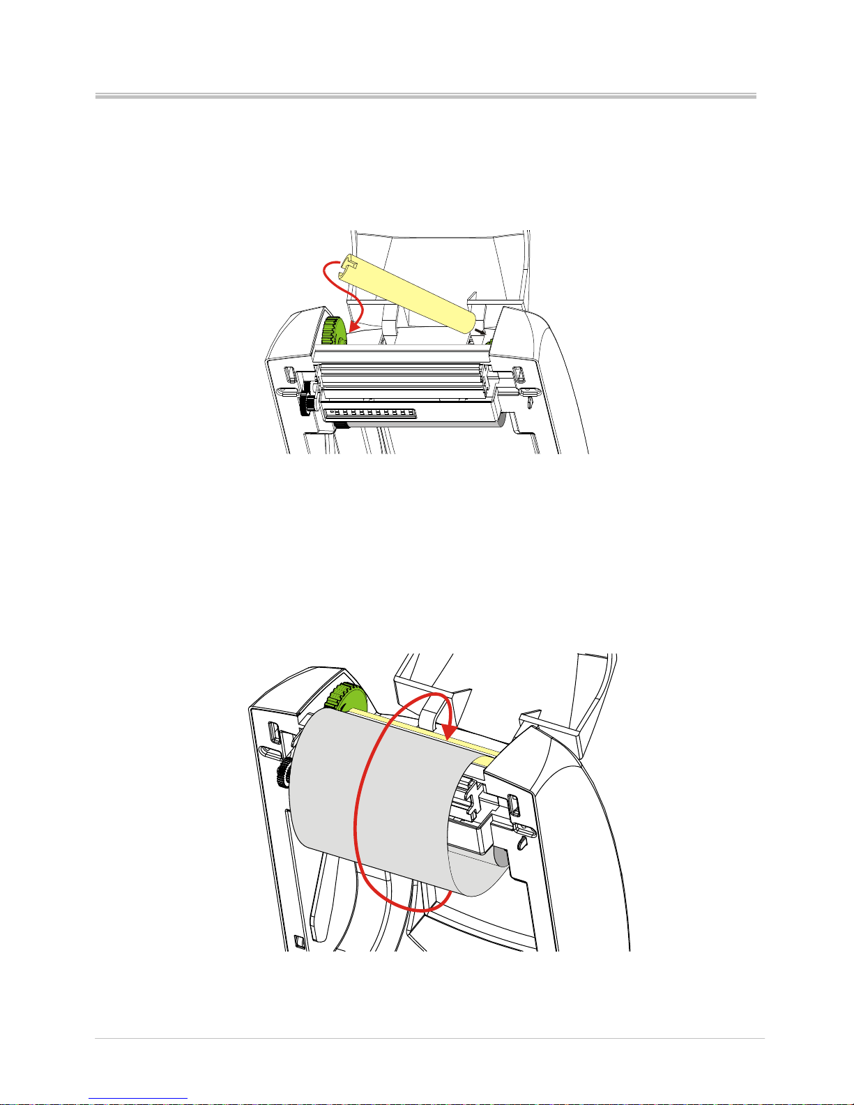
5. Insert an empty media core into the take up spindle. Rotate the take up hub
until the notches align and lock on the left side of take up hub.
6. Pull the ribbon out from the roll and stick it with the adhesive tape on the
empty ribbon take up core.
Page 12
Ver:1.1
s4 series user’s manual
7
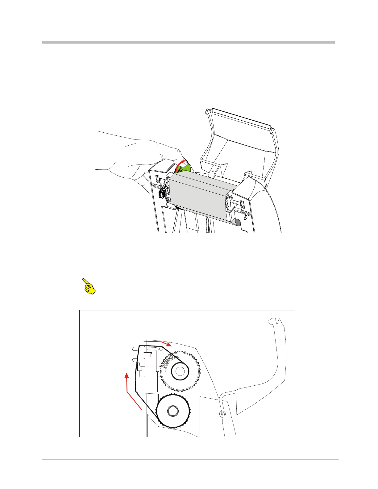
7. Rotate the take up hub on the left side of ribbon spindle till the ribbon is
pulled tight.
Note: The loading path of ribbon roll (outside wound)
Page 13
Ver:1.1
s4 series user’s manual
8
2.2 Loading the media
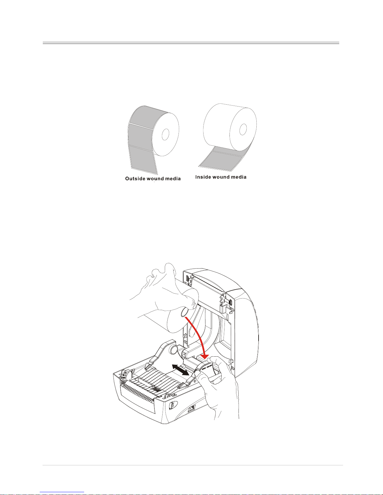
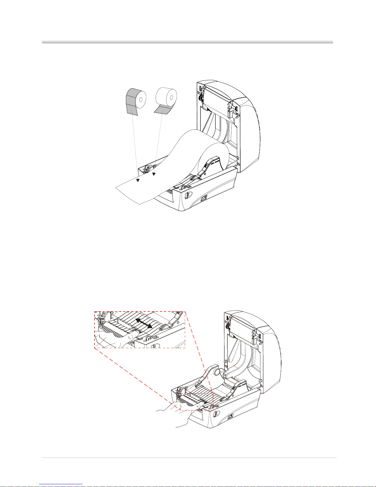
Whether the roll media is inside or outside wound, they could be used in this
printer and loaded in the same way.
1. Open the printer cover by pulling the release latch toward the front of
printer.
2. Press the holder latch and pull the media holders open. Place the media
roll on the holders and push media holder toward the roll by pressing the
holder latch. Release the latch when the media is on the holder firmly.
Page 14
Ver:1.1
s4 series user’s manual
9
3. Pull the media so it could extend out the printer. Please make sure the
printing surface is facing up.
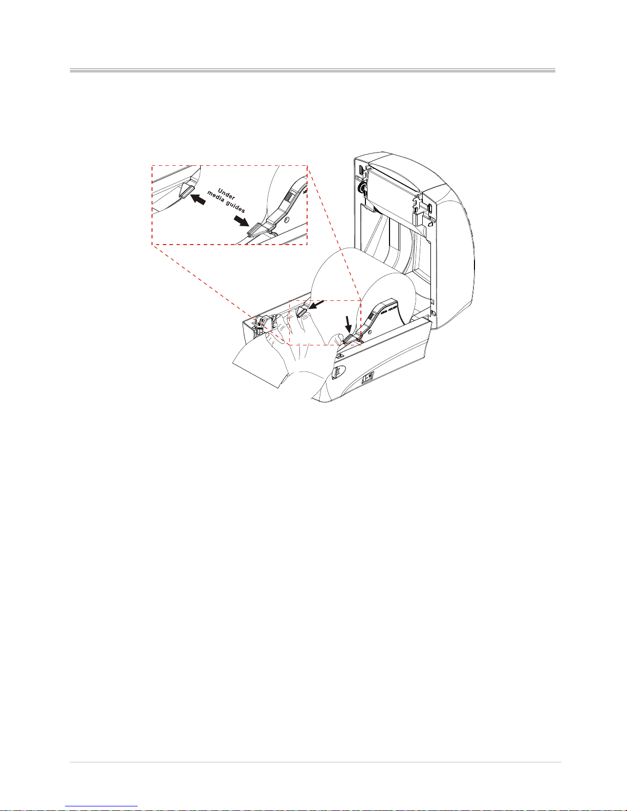
4. Before pushing the media under the guides, adjust the label senor to
appropriate position to detect the labels with gap, hole or black mark.
Page 15
Ver:1.1
s4 series user’s manual
10
5. Push the media under the both sides of guides.
Page 16
Ver:1.1
s4 series user’s manual
11
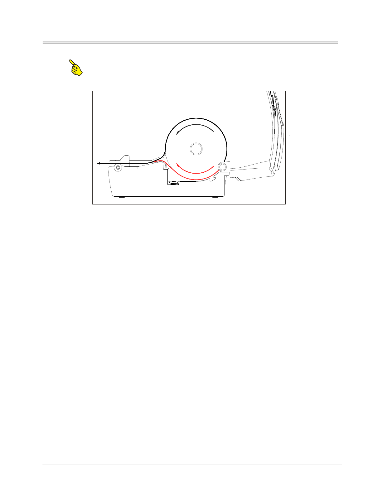
Note: The loading path of label roll (inside and outside wound)
Page 17
Ver:1.1
s4 series user’s manual
12
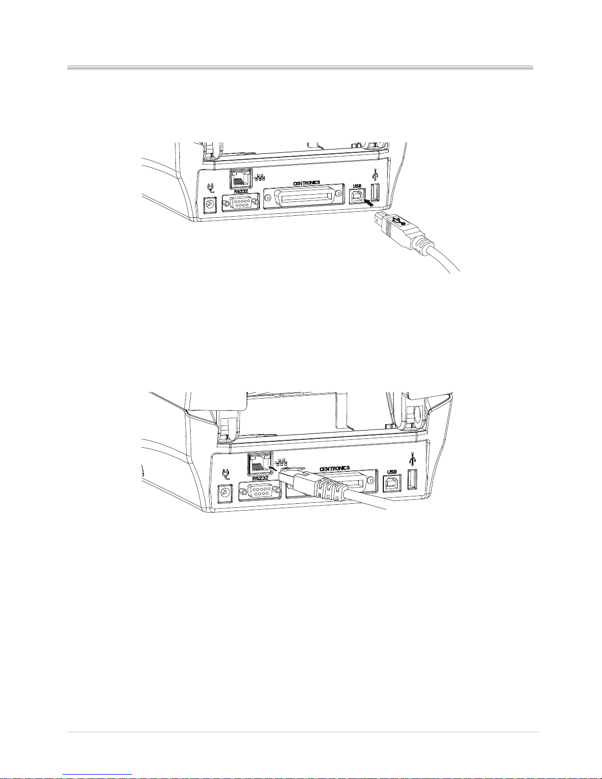
2.3 Connecting interfaces
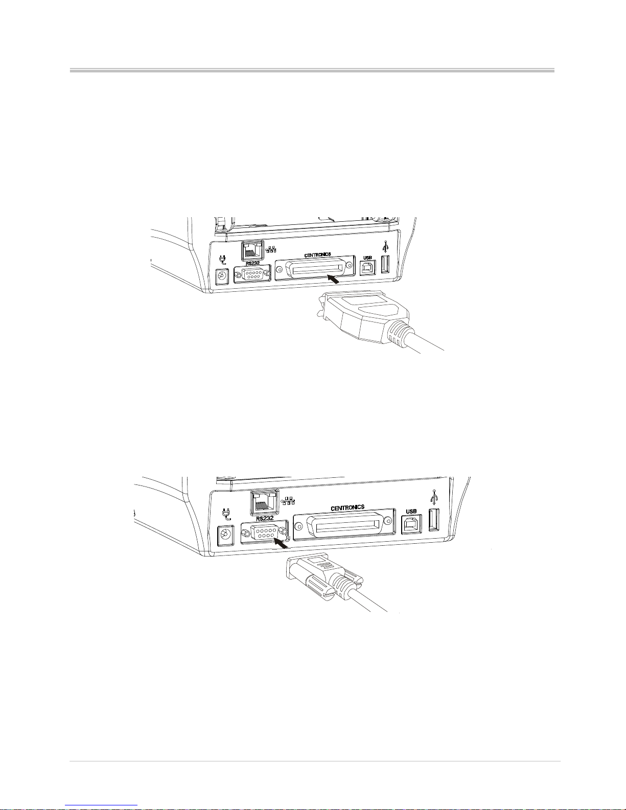
The following interfaces could be connected to PC to operate the printer:
2.3.1 Centronics port (Parallel port)
2.3.2 RS-232 port (Serial port)
Page 18
Ver:1.1
s4 series user’s manual
13
2.3.3 USB Slave
2.3.4 Ethernet (Option)
Page 19
Ver:1.1
s4 series user’s manual
14
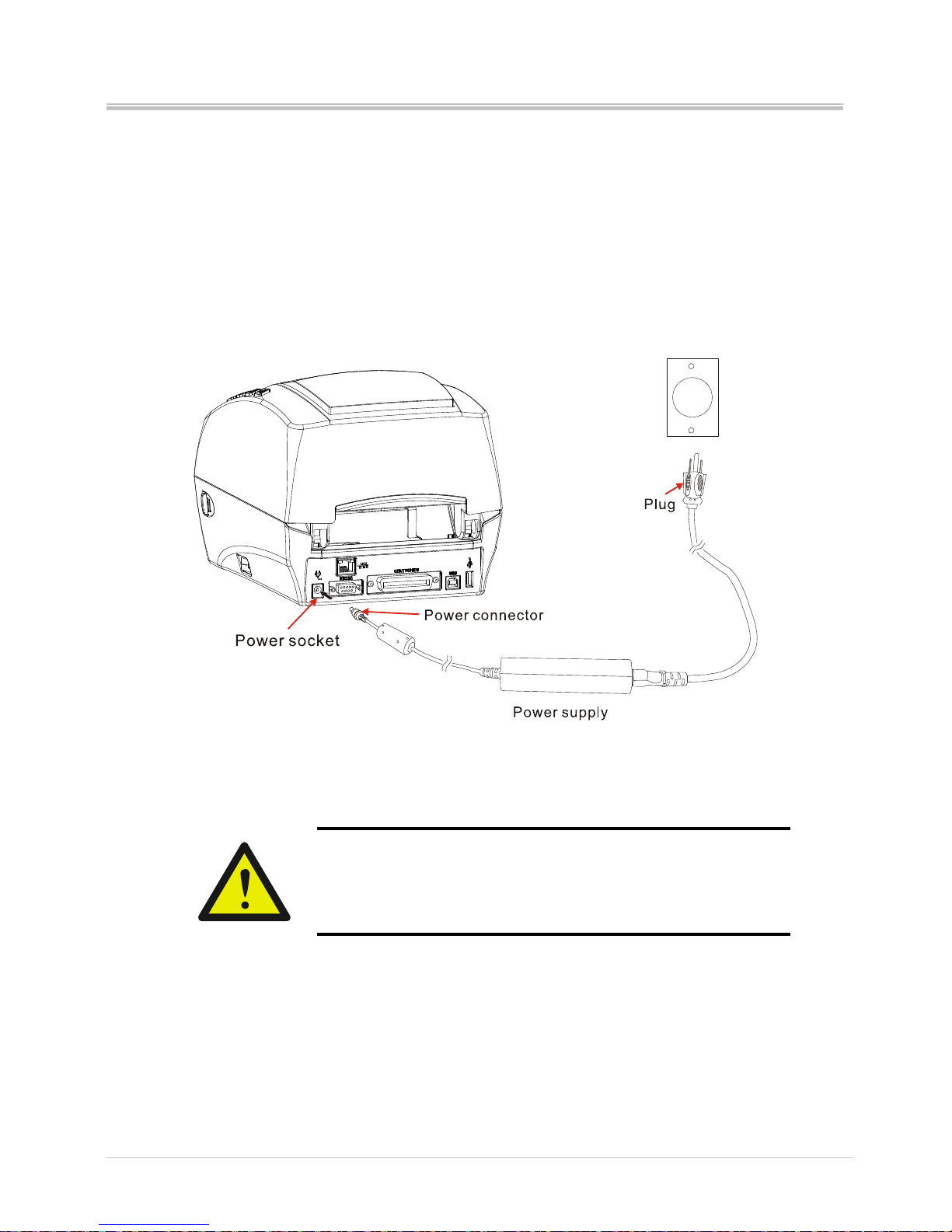
2.4 Power on the printer
1. Make sure the printer power switch is off
2. Plug the power connector into the power socket at the rear side of printer.
3. Plug the power cord on the power outlet.
4. Turn the printer power switch to on.
Caution. Please ensure that the printer power is off
before connecting the interface cable. Connecting the
interface cable while printer power is on might cause the
damage on printer.
Page 20
Ver:1.1
s4 series user’s manual
15
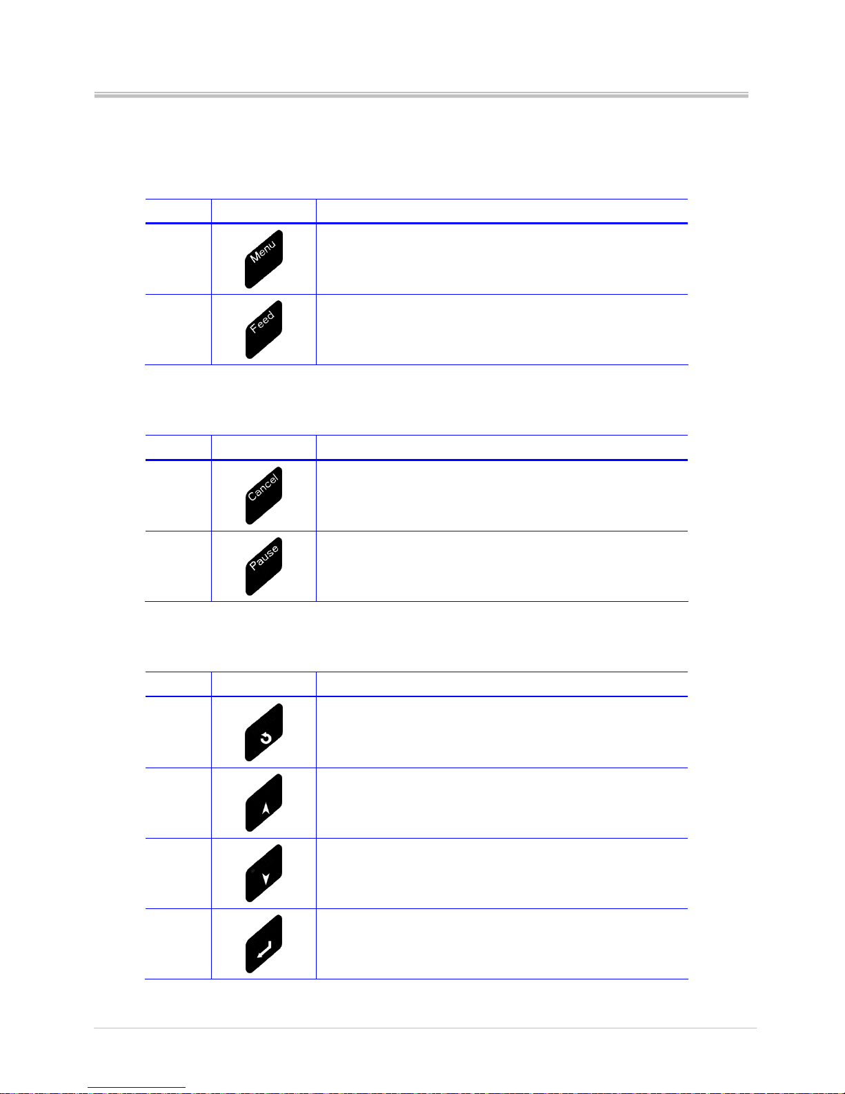
2.5 Control panel
The key functions are available under the printer READY mode
Button Appearance Function
Menu
Enter the menu list to setup the printer configuration
Feed
Feed a blank label
The key functions are available under the printer PRINTING mode
Button Appearance Function
Cancel
Stop and cancel the current printing job
Removes the error status when problem is
resolved.
Pause
Stop and restart the printing process
The key functions are available in Menu System
Button Appearance Function
Return
Return back to previous menu level
Up
Scroll up the menu options
Increase the parameter values
Down
Scroll down the menu options
Decrease the parameter values
Enter
Confirm the selected option
Page 21

Ver:1.1
s4 series user’s manual
16
Buttons light
Cancel
Flash in red
Bi-sound
Error message
Ribbon out (error)
Label out (error)
Top cover opened
Page 22
Ver:1.1
s4 series user’s manual
17
3. Printer options
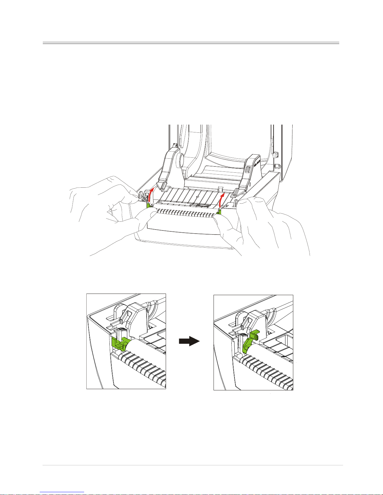
3.1 Peeler installation
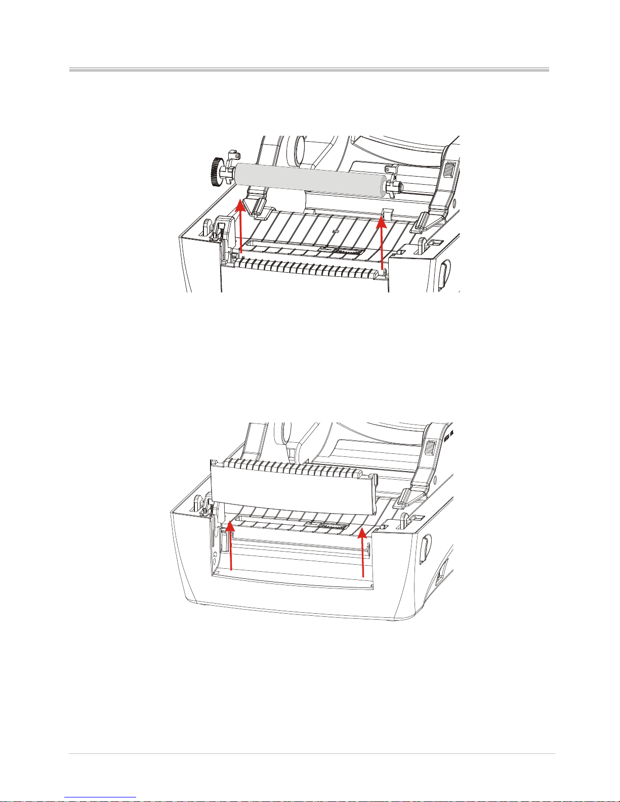
1. Push the platen bearing tabs on the right and left sides upwards and rotate
them backwards to the end.
Page 23
Ver:1.1
s4 series user’s manual
18
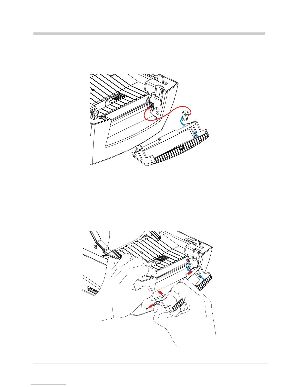
2. Lift vertically the platen from the bottom case of printer.
3. Lift vertically the front cover from the bottom case of printer.
Page 24
Ver:1.1
s4 series user’s manual
19
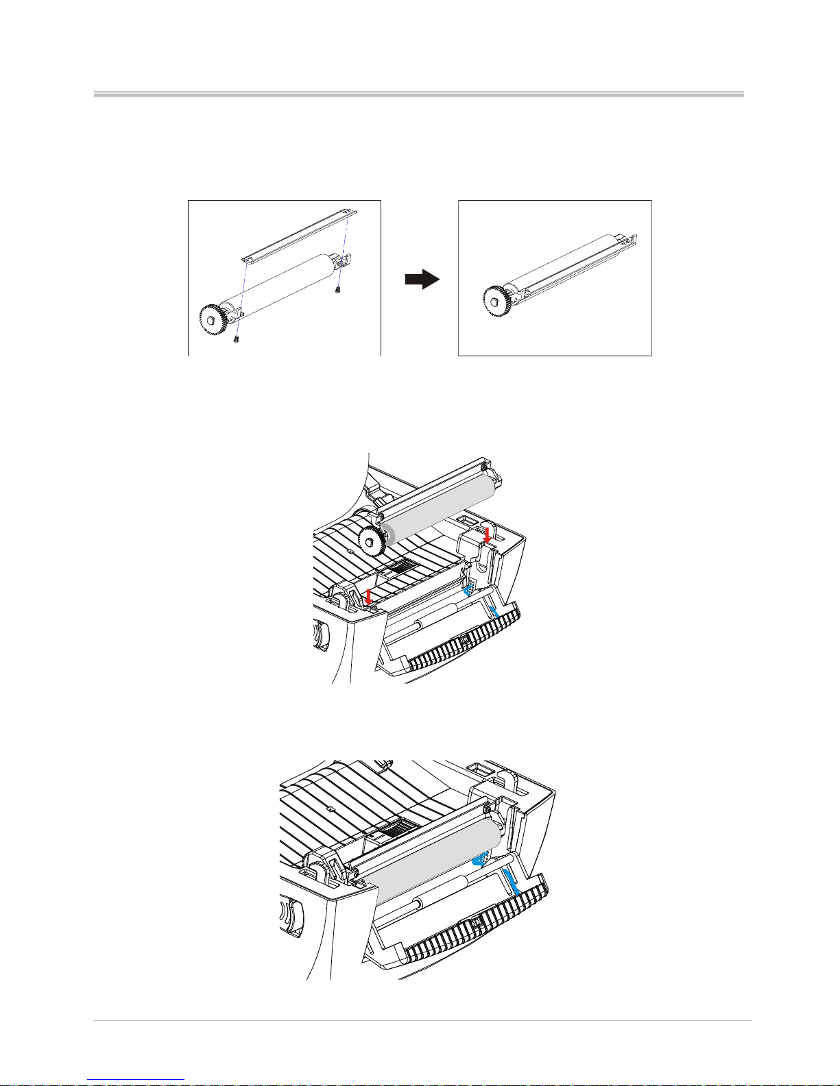
4. Insert the peeler cable to printer. (Please follow the correct connector side
as figure shown to insert the cable)
5. Insert firstly the right side of peeler module to the relative holes of printer
(arrow 1), press the lower part of left side of module (arrow 2), then push
the left side of module to the relative holes of printer to fix firmly the peeler
module on printer (arrow 3).
Page 25
Ver:1.1
s4 series user’s manual
20
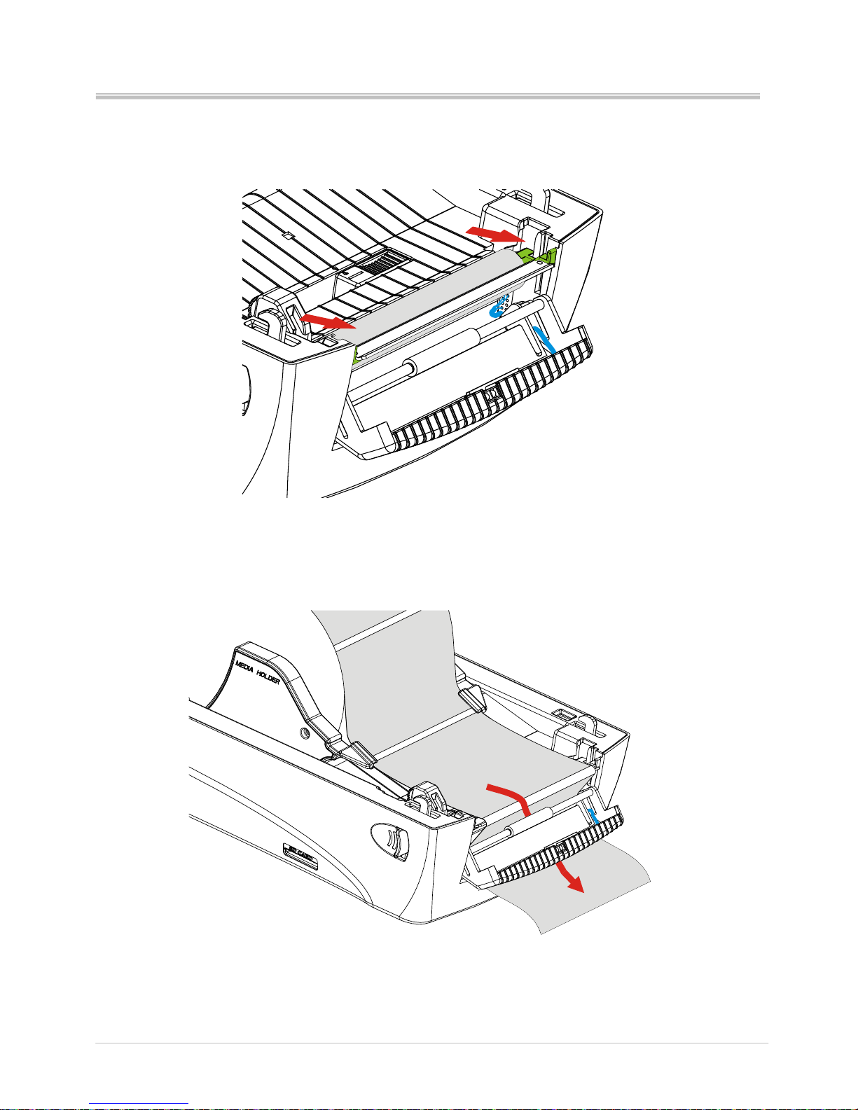
6. Screw up the metal plate on the platen. The metal plate with arrow symbol
is upward side.
7. Put the platen screwed with metal plate back to printer
8. Assure the platen is fixed firmly in printer.
Page 26
Ver:1.1
s4 series user’s manual
21
9. Push the platen bearing tab forward to lock the platen.
10. Lead the label through the back of peel-off bar, as figure show.
Page 27
Ver:1.1
s4 series user’s manual
22
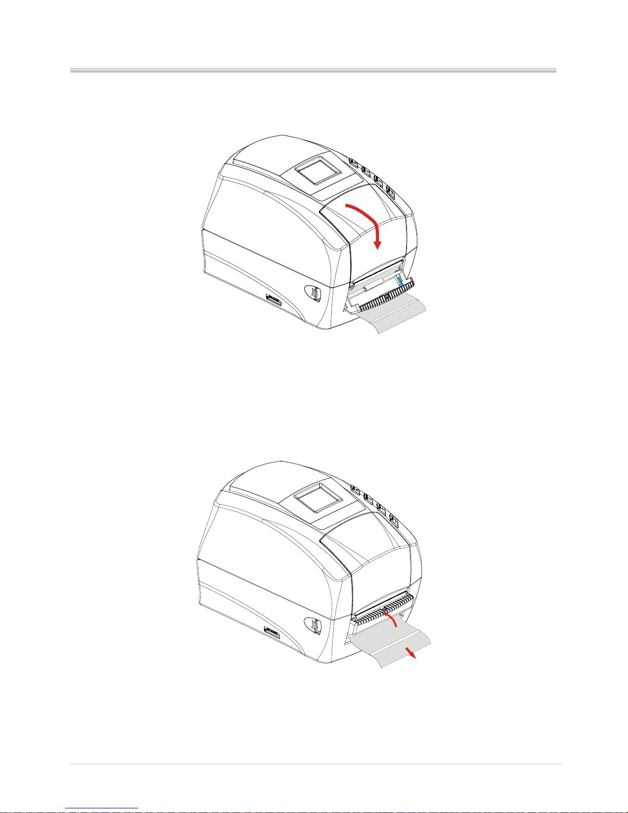
11. Close the top cover
12. Pull the label to the direction as the figure show, then push the peel-off
panel back to printer.
Page 28
Ver:1.1
s4 series user’s manual
23
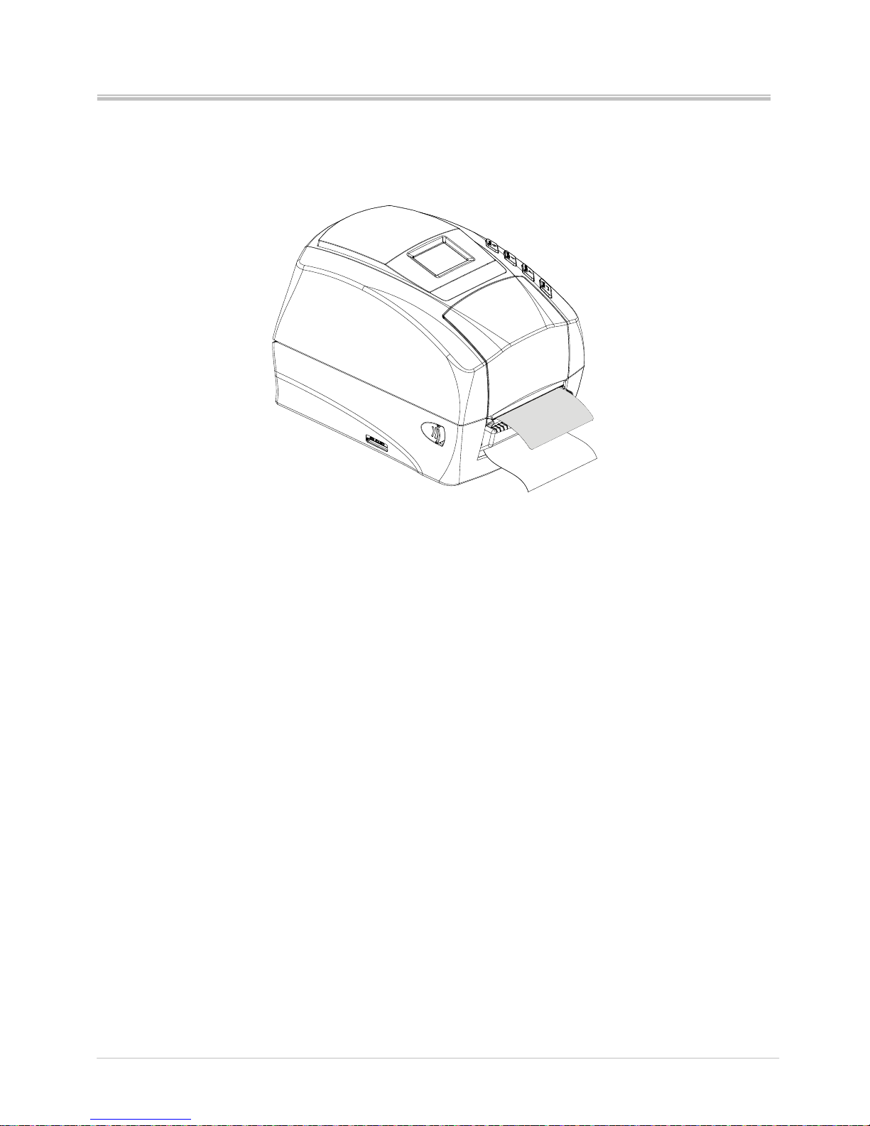
13. Press the Feed button to test the peeler function.
Page 29
Ver:1.1
s4 series user’s manual
24
3.2 Cutter installation
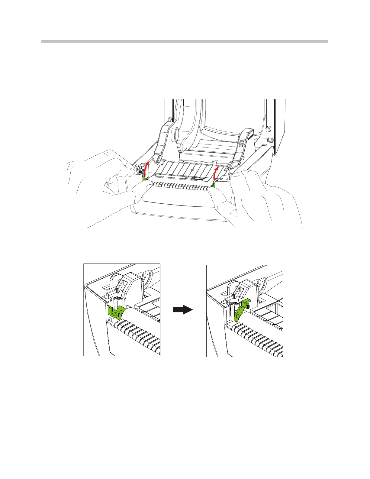
1. Push the platen bearing tabs on the right and left sides upwards and rotate
them backwards to the end.
Page 30
Ver:1.1
s4 series user’s manual
25
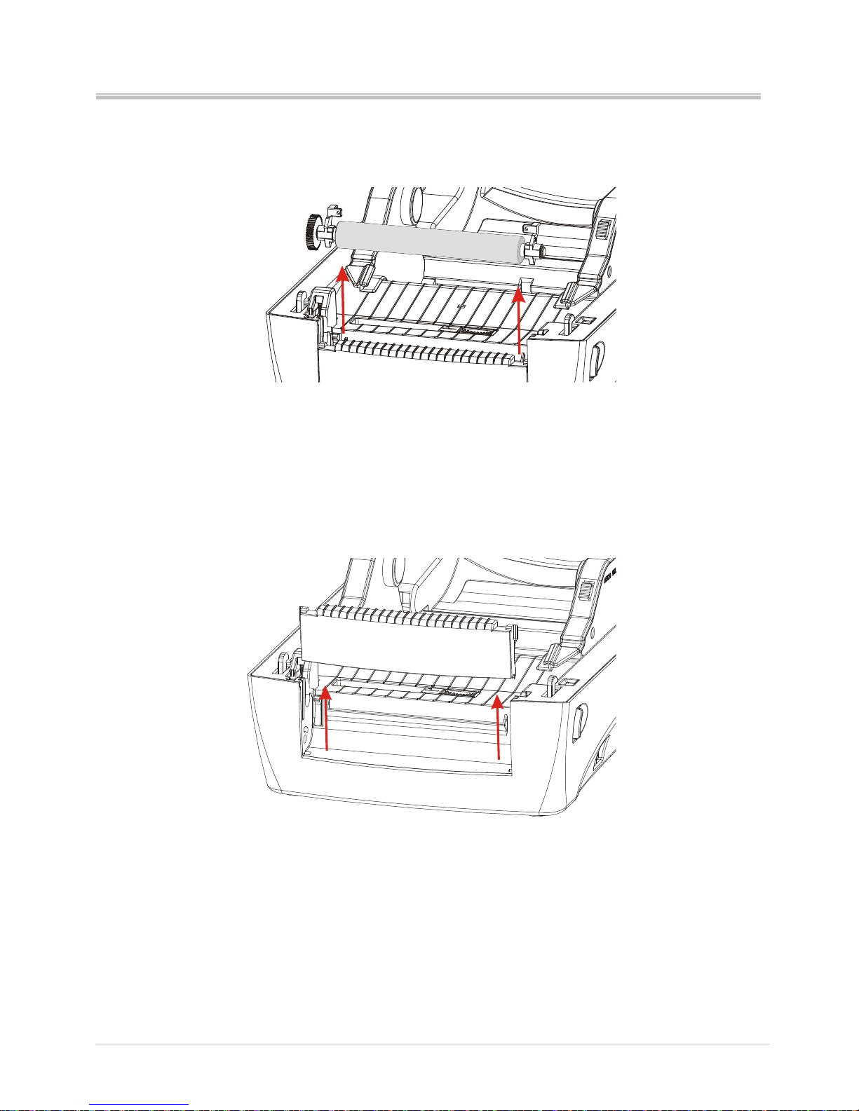
2. Lift vertically the platen from the bottom case of printer.
3. Lift vertically the front cover from the bottom case of printer.
Page 31
Ver:1.1
s4 series user’s manual
26
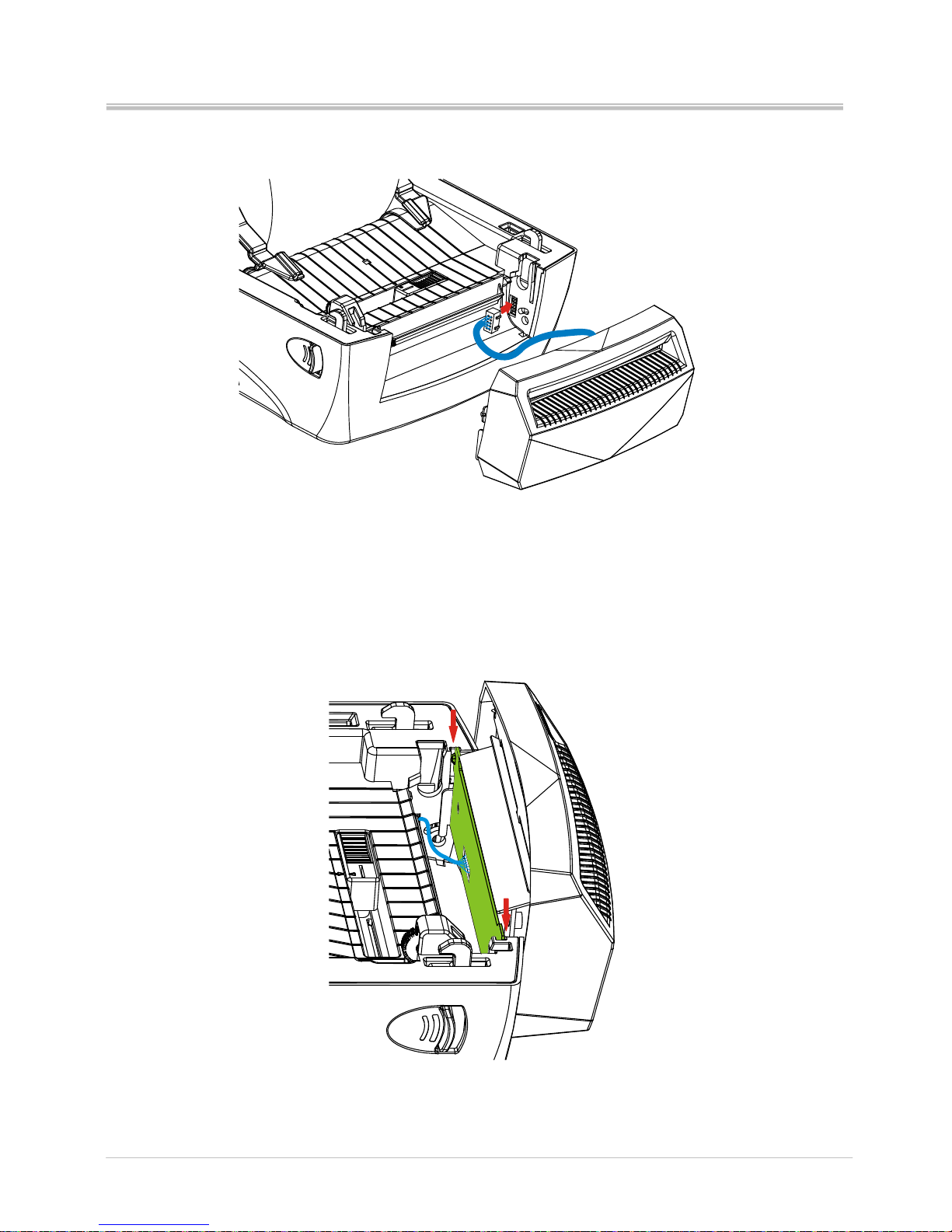
4. Connect the cutter cable to printer
5. Slide vertically the hooks of cutter both side into the slot
Page 32
Ver:1.1
s4 series user’s manual
27
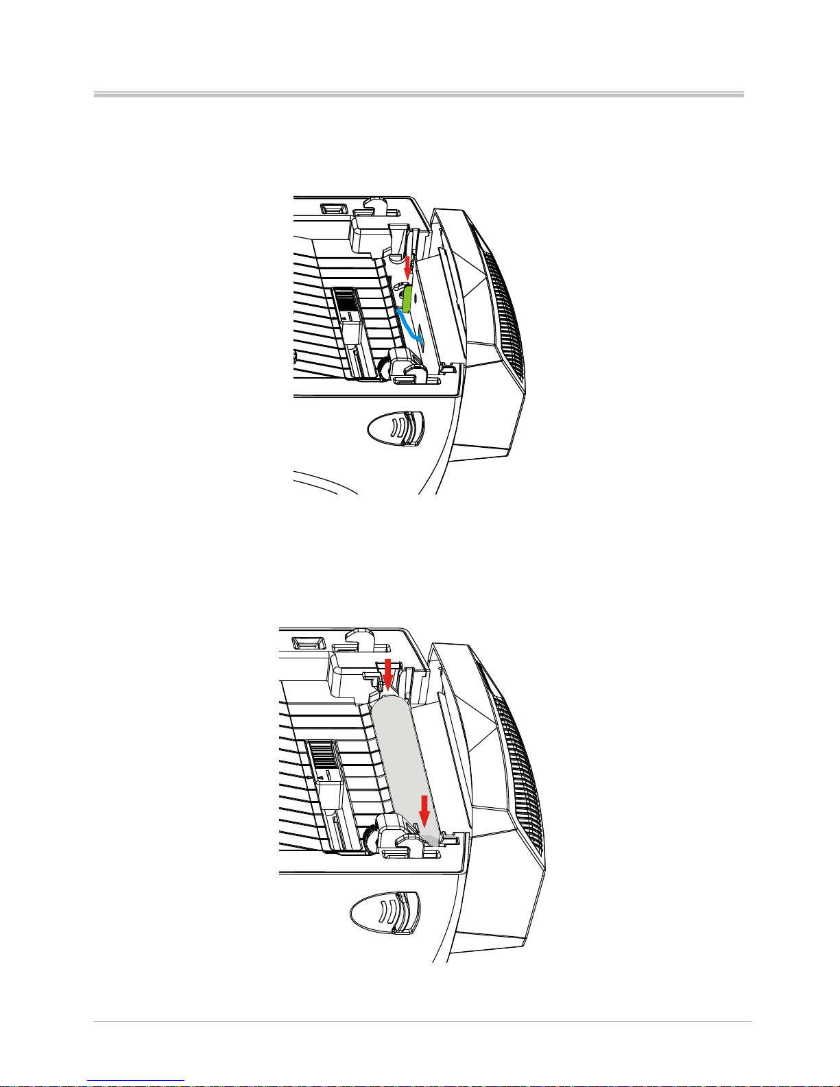
6. Push the cutter hooks to the bottom of two hooks slots, and make sure that
lower hooks are fixed firmly on the hooks holes.
7. Put the platen back in the printer.
Page 33
Ver:1.1
s4 series user’s manual
28
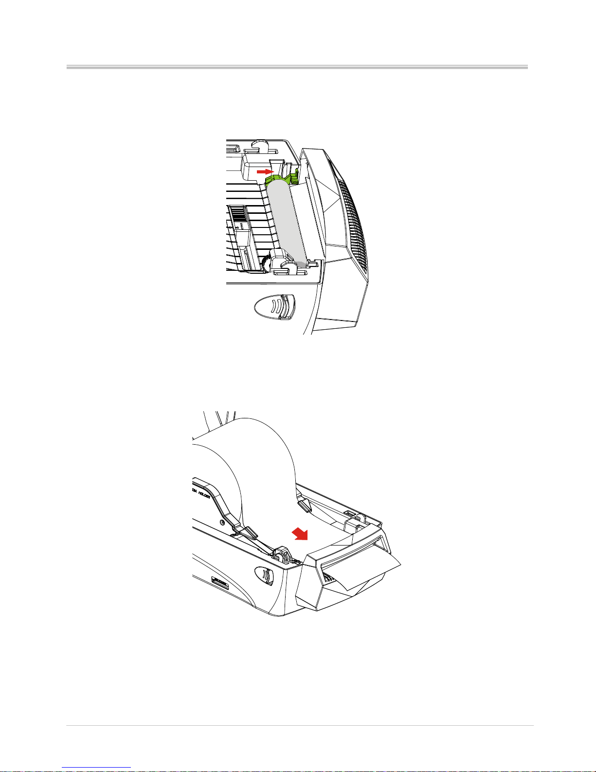
8. Lock the platen bearing tabs
9. Thread the label through the cutter inside slot and press the label under the
media guides.
Page 34
Ver:1.1
s4 series user’s manual
29
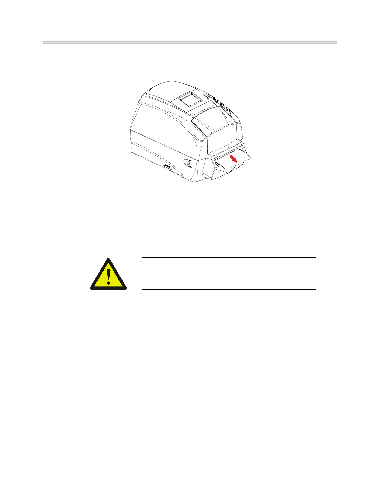
10. Close the printer top cover
Please do not touch or insert your fingers into the
cutter mouth while cutter is active. It will cause
extremely hurt.
Page 35
Ver:1.1
s4 series user’s manual
30
4. LCD screen icons
4.1 LCD screen information
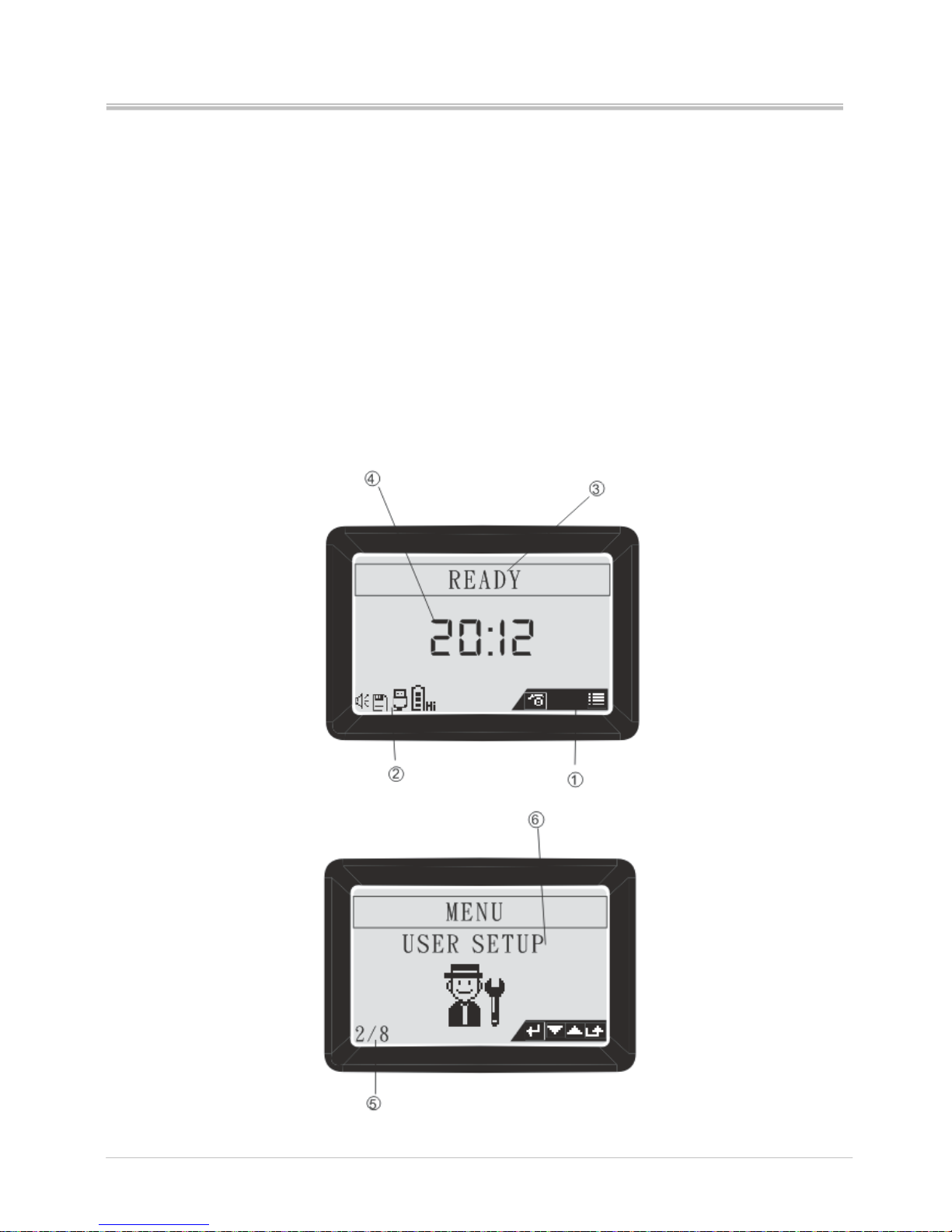
LCD screen information consists 5 parts to show the printer status.
Buttons status bar
Device status (when printer is in Ready status)
Printer current status and setting level
Time and setting icon
Menu pages
Printer current setting level, it shows only when printer is in menu function
Page 36
Ver:1.1
s4 series user’s manual
31
4.2 Graphic symbol on LCD screen
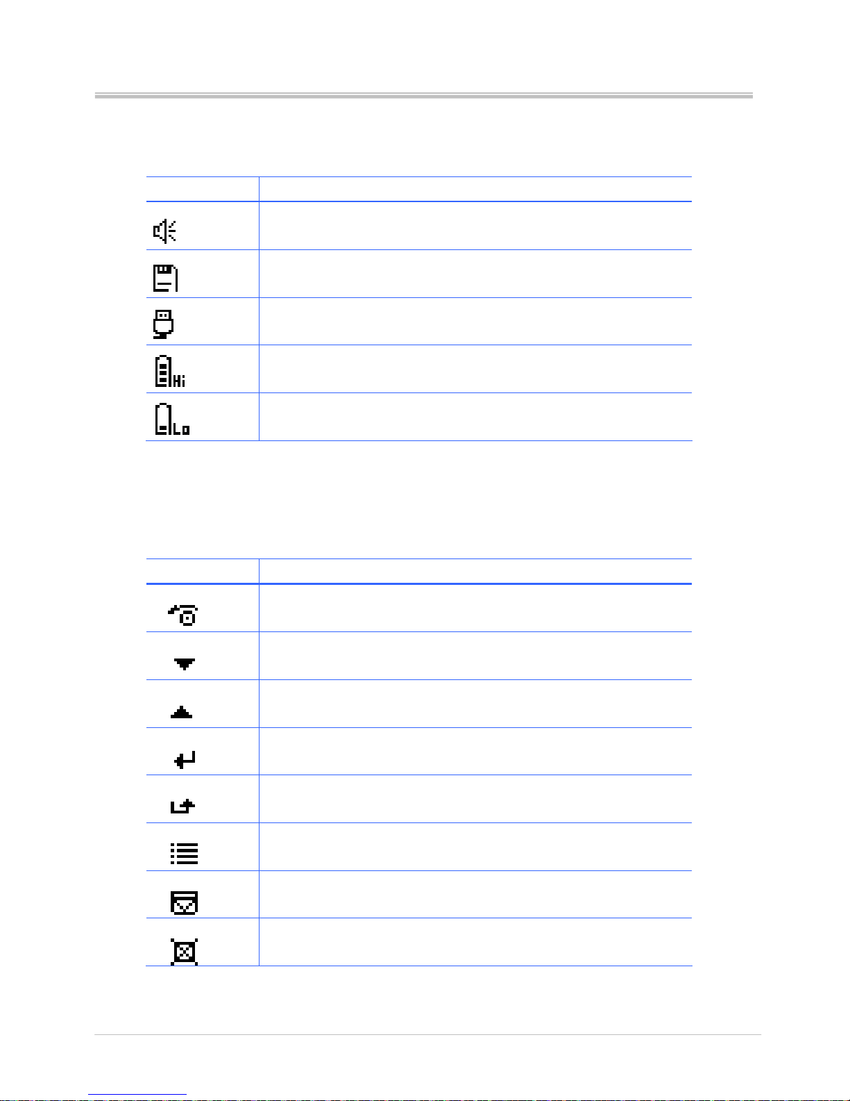
Device status bar
Symbol Description
Buzzer on (buzzer symbol will be shown when buzzer is set
to on)
SD card inserted (SD card symbol will be shown when SD
card is inserted)
USB master interface (keyboard or scanner) inserted (USB
master symbol will be shown when interface is inserted
RTC battery power is full
RTC battery power is running out
Button status bar: the symbol will be shown on the button status bar when
the button function is available.
Symbol Description
Feed labels.
Scroll down
Scroll up
Enter
Escape
Main menu
Pause
Cancel
Page 37
Ver:1.1
s4 series user’s manual
32
5. Configuration
5.1 Menu structure
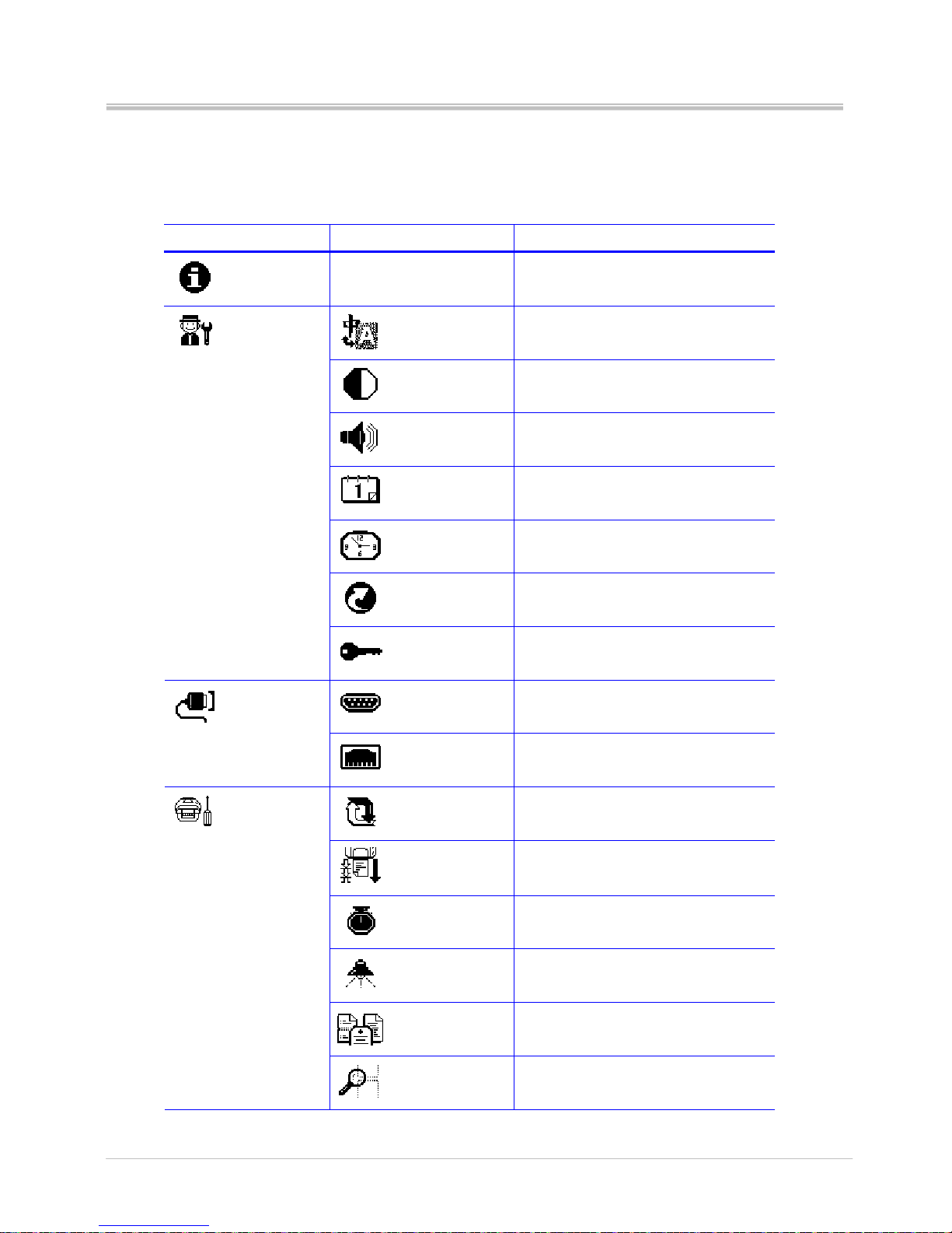
Main menu Sub-menu Description
Information
Printer configuration information
Language
Change menu language
LCD Contrast
Contrast of LCD
Buzzer Volume
Adjust the buzzer volume
Date
Set the RTC Date
Time
Set the RTC time
Default
Initiate to factory default
User Setup
Password
Set the password to lock the change
of parameter
RS-232
Set RS-232 parameter
Comm. Setup
Ethernet
Ethernet status and set configuration
Transfer mode
Thermal transfer or thermal direct
Print mode
Set to peeler, cutter or tear off
function
Speed
Printing speed
Darkness
Printing heat value
Label type
Select the label type
Print Setup
Gap sensor
Select label sensor type
Page 38
Ver:1.1
s4 series user’s manual
33
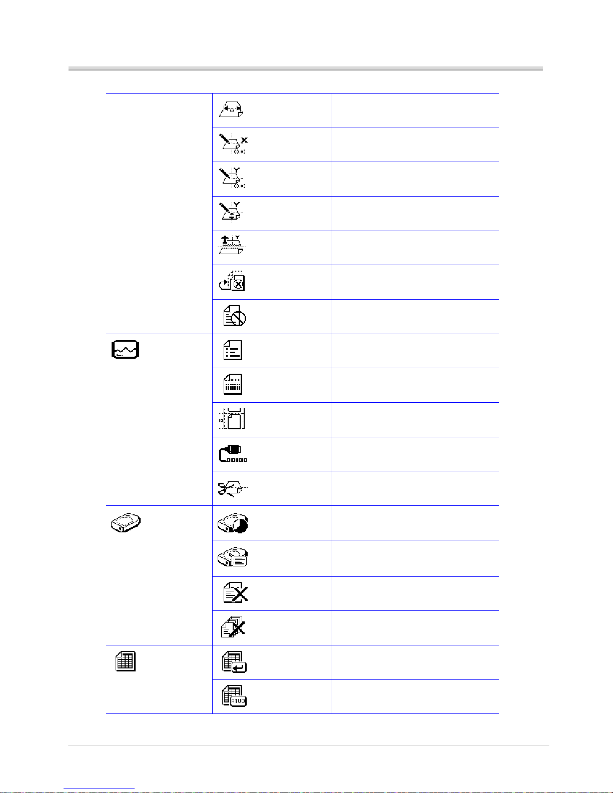
Print width
Set the print width
Print X offs
Adjust the origin of printer horizontal
coordinate
Print Y offs
Adjust the origin of printer vertical
coordinate
TPH Y offs
Set the print head vertical offset
Back Y offs
Set the label stop position for peeler,
cutter or tear-off mode
Error reprint
Reprint the previous label when error
occurs
Cancel mode
Stop printing the current job
Print Config.
Print the printer configuration
Print test
Print the test pattern
Label calibration
Calibrate the label
Dump mode
Print the dump data
Test
Cutter
Test cutter function
Free size
Show the free memory size in
SDRAM and SD card
List
List the forms, images and fonts in
memory device
Delete files
Delete separately the stored forms,
images and fonts in memory
Memory
Clear memory
Delete all stored forms, images and
fonts in the memory
Run the form
Execute the stored form in memory
Form
Auto form
Execute automatically the selected
form as the printer is power on
Page 39

Ver:1.1
s4 series user’s manual
34
F/W update
Update firmware directly from the SD
card
Page 40
Ver:1.1
s4 series user’s manual
35
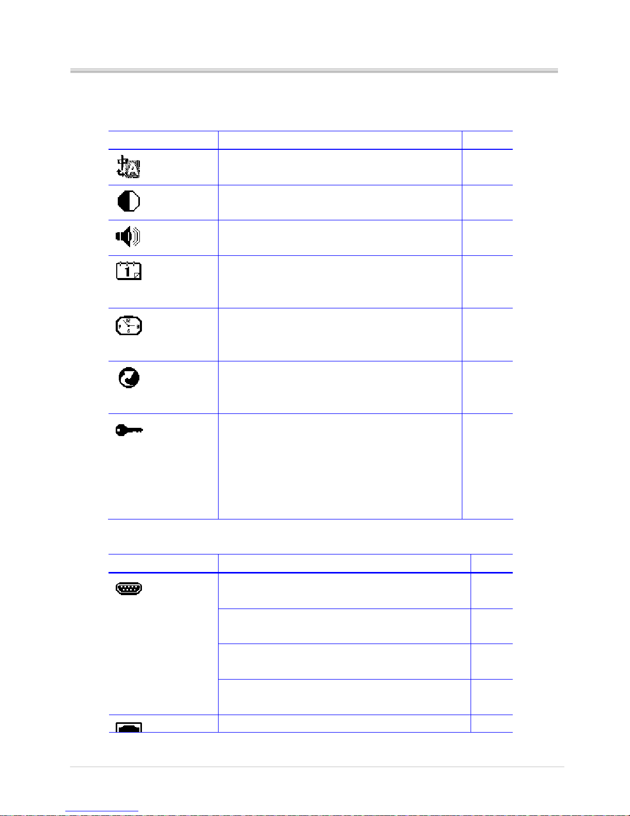
5.2 Parameters setup
5.2.1 User Setup
Parameter Explanation Default
Language
Change menu language
Languages: English, Traditional Chinese
English
LCD Contrast
Contrast of LCD display
Value: from 0~5
Level 2
Buzzer volume
Adjust the buzzer volume
Value: off, 1~3
Volume 1
Date
Set Real-Time clock date
This parameter allows users to set the date
Type: Year/Month/Date
None
Time
Set Real-Time clock time
This parameter allows users to set the time
Type: hour/minute/second
None
Default
Set the parameters to factory default
This parameter allows users to set all the parameters
back to factory default
None
Password
Set the password to protect the parameters
This function allows users to set the password to lock
the parameters change of User, Communication and
Print Setup to prevent the other users to change it
carelessly.
Password value range: 0000~9999
0000
5.2.2 Communication setup
Parameter Explanation Default
Baud rate
Selection: 1200 ~115200
9600
Parity
Selections: None, Odd, Even
None
Data bits
Selections: 7, 8 bits
8 bits
RS-232
Stop bits
Selection: 1, 2
1
Status (Ethernet)-Show only the Ethernet status
Page 41

Ver:1.1
s4 series user’s manual
36
Config. Method-DHCP or Static IP
IP address
Net Mask
Gateway
MAC address
Configure (Ethernet)-Configure the Ethernet
DHCP-Issuing the IP address by DHCP server
Static IP- Issu ing the IP address by operator
DHCP
Page 42
Ver:1.1
s4 series user’s manual
37
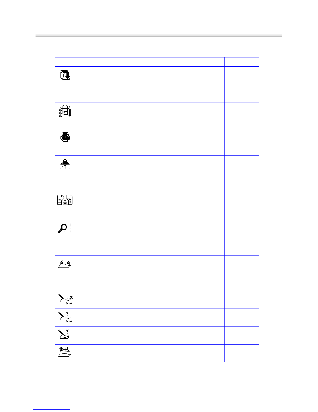
5.2.3 Print Setup
Parameter Explanation Default
Transfer mode
Change the printing mode
This setting could change the printing mode
Selection: By Command, Direct thermal, Thermal
Transfer
By command
Print mode
Select the print mode
This setting changes the label delivery mode.
Selection: Normal, Tear off, Peel off, cut
Normal
Speed
Adjust the printing speed
This setting could change the printing speed
Selection: 1, 2, 3, 4 dpi
3
Darkness
Adjust print darkness
This setting could adjust the printing quality by the
printing heat
Selection: 0~15
8
Label type
Select the label type
This setting could select the media.
Selection: Gap/Notch, Mark, continuous
Gap/Notch
Label sensor
Change the label sensor type
This setting could change the convenient sensor
type to detect the label.
Selection: By command, see-through, reflective
By command
Print width
Adjust the print width
This setting determines the printable area by
setting the printing dot.
Selection: 120~832 dot
832 dot
Print X offs
Adjust the horizontal origin of coordinate
Selection: -80~+80 dot
00
Print Y offs
Adjust the vertical origin of coordinate
Selection: -80~+80 dot
00
TPH Y offs
Adjust the print head vertical offset
Selection: -120~+120 dot
000
Back Y offs
Set the label stop position
Selection: -080~+120 dot
000
Page 43

Ver:1.1
s4 series user’s manual
38
Error reprint
Repeat the previous label when error occurs
When the error occurs and the printing stops, this
function will reprint the label which was
interrupted.
Selection: Enable, Disable
Enable
Cancel mode
Set the cancel mode
This function allows users to cancel printing
immediately or after completing a label
Selection: Page complete, immediate
Page
complete
Page 44
Ver:1.1
s4 series user’s manual
39
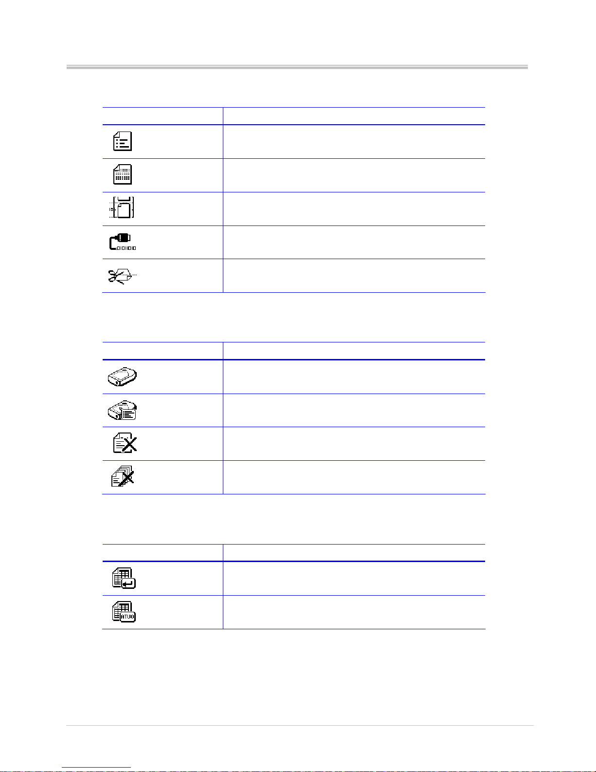
5.2.4 Test
Parameter Explanation
Print Configuration
Print all the printer configurations
Print test
Print the programmed file to verify if the printer works
properly
Label calibration
Calibrate the label
Dump mode
Print the Dump mode information
Cutter
Cutter function test
5.2.5 Memory
Parameter Explanation
Free size
Shows the available memory size on SD card and SDRAM
List
List the stored forms, images and fonts in SD card and
SDRAM.
Delete file
Delete the stored forms, images and fonts in SD card and
SDRAM.
Clear memory
Clear all the stored forms, images and fonts in SD card and
SDRAM
5.2.6 Form
Parameter Explanation
Run the form
Execute the form stored in the SD card or SDRAM
Auto form
This function allows users to run automatically the selected
form stored in memory when users re-power on the printer.
Page 45

Ver:1.1
s4 series user’s manual
40
5.2.7 Warning message
Icon Explanation
No form found
Form in SD card or SDRAM is not found.
Check if the files are exactly stored in the memory device
No Image found
Image in SD card or SDRAM is not found.
Check if the image is exactly stored in the memory device
No font found
Font in SD card or SDRAM is not found.
Check if the font is exactly stored in the memory device
No F/W found
Firmware files are not stored in the SD card when updating the
firmware.
No Batt. found
Battery is not installed in the printer when setting time and date
Check if the battery power runs out or not installed well
Password error
Wrong password is entered
Enter the correct password to modify the protected parameters
SD lock
Printer cannot write the data to SD card
Unlock the SD card
No cutter found
Cutter is not installed on printer when execute the cutter test
No SD found
SD card in not installed in printer when updating the printer
Check if printer is well inserted in printer
Cutter jam
Cutter jams when execute the cutter test
Check if the labels stick in cutter
No Ether found
Ethernet module is not installed in printer
Check if the Ethernet module is installed or well installed
Flash ROM Full
Internal flash ROM is full
Delete un-necessary files to store the current files
Page 46
Ver:1.1
s4 series user’s manual
41
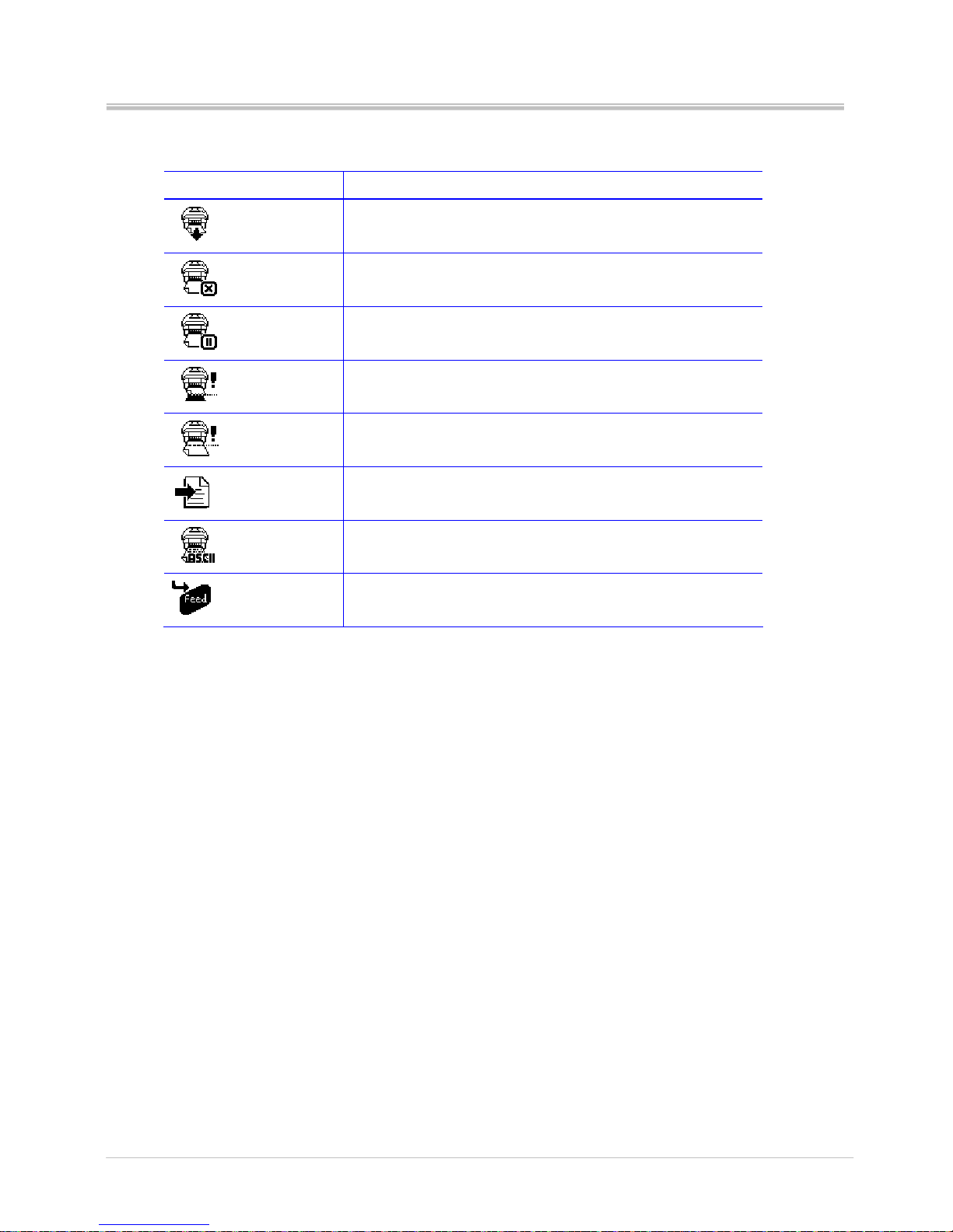
5.2.8 Printer status
Icon Status description
Feed
Feeding the label
Cancel
Cancel the current printing job.
Pause
Pause the current printing job.
Wait peel
Wait to peel the printed label to print the next label
Wait on demand
Wait to press the feed button to print next label.
(*This function is available only on sending the command)
Value saved
Save the change of parameters to printer
Dumpping data
Catch the data from communication port and send to printer to
print out.
Push to cal
Press the “Feed” button to calibrate the label.
(*This function is available on “Label Cal”)
Page 47
Ver:1.1
s4 series user’s manual
42
6. Troubleshooting
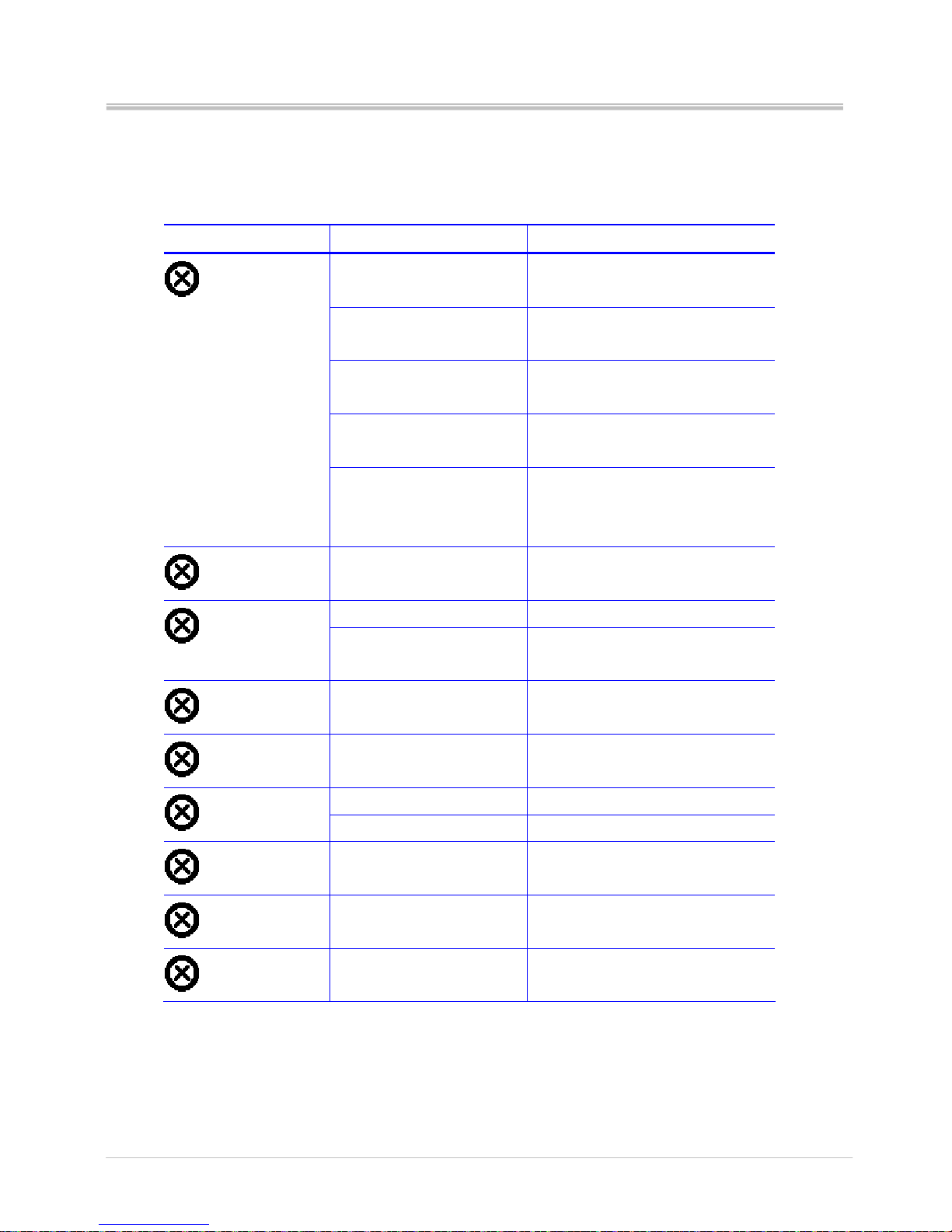
6.1 LCD error message
LCD Displayed Possible problem Resolution
Improper sensor type Ensure the sensor type, reflective or
see-through, is selected correctly
Label senor cable is
disconnected or loose
Reconnect or tighten up the sensor
cable
Sensor windows are dirty Clean the receiver sensors and
emitter sensor
Improper media sensor
position
Adjust the media sensor to correct
position
Label gap out
Load the continuous label,
but the label type is set to
Gap/notch or Mark type
Load the correct media or set the
label type to current using media
type
Label out
Label runs out Reload new media roll
Ribbon runs out Reload new ribbon roll
Ribbon out
Ribbon roll is not loaded
correctly
Ensure the ribbon supply and take
up core are fixed correctly
Cover open
Printer cover is open Close the printer cover
Update fail
Firmware update fails Re-update the firmware
TPH cable is disconnected Connect the TPH cable
TPH fail
TPH is faulty damaged Replace a new TPH
Check sum error
Firmware update fails. Re-update the firmware
No cutter found
Cutter is not installed when
printing
Check if cutter is installed in printing
Cutter jam
Cutter jams when printing Check if labels stick in cutter
Page 48

Ver:1.1
s4 series user’s manual
43
7. Specifications
7.1 General specifications
Resolution 200 dpi (8 dots/mm)
Print mode Dire ct Thermal/Thermal Transfer
CPU 32-bit CPU
Memory RAM: 8MB SDRAM
ROM: 4MB Flash ROM
Expendable slot for SD card (up to 4GB)
Print speed 1” to 4” ips
Max. print length 150” (3810mm)
Print width 4.1” (104mm)
Sensor type Moveable see-through and reflective sensor
Label sensor
Ribbon sensor
Cover open sensor
Display Backlight LCD display 128x64 dots
Control panel 4 multi-functional keys
4 status LED light
1 error LED light
Media Maximum label width: 4.33” (110mm)
Minimum label width: 0.59” (15mm)
Maximum roll diameter: 5” (127mm)
Core diameter: 1.0” (25.4mm)
Media thickness: 0.002” (0.06mm) to 0.0075” (0.2mm)
Media type: Continuous, die-cut, tag, fan-fold, black mark
Ribbon OD: 1.535” (39mm)
Max length: 100m
Width: 1.0” (25.4mm) to 4.3” (110mm)
ID: 0.5” (12.7mm)
Ribbon type: Wax, wax/resin, resin
Interfaces Serial port-RS-232
Parallel port
USB master port
USB slave port
Page 49

Ver:1.1
s4 series user’s manual
44
Ethernet port 10/100Mbps (option)
1D barcodes
Code39 standard or extended, Code39 with check digit, Code93,
Code128 UCC, Code128 auto A,B,C modes, Codabar, EAN8, EAN8/13
2&5 digit add-on, EAN13, Interleaved 2 of 5, Interleaved 2 of 5 with check
digit, Interleaved 2 of 5 with human readable check digit, UCC/EAN 128,
UPC A, UPC A 2&5 digit add-on, UPC E, UPC E 2&5 digit add-on, UPC
Interleaved 2 of 5
2D barcodes
Data Matrix, MaxiCode, PDF417
Fonts 5 internal expandable bitmap fonts (alpha-numeric)
2 internal expandable bitmap fonts (numeric only)
Downloadable soft font
4 directions: 0, 90, 180, 270 degrees
Image PCX, Direct binary graphic
Options Peeler kit
Cutter
Ethernet module
Expansion memory card
Power Switching power adapter
Input: 100 to 240V, 1.8A, 50~60Hz
Output: 24V, 2.5A
Audio Beep sound when error occurs
Environment
Operation: 5℃ to 45℃(40℉ to 1 12.9℉)
Storage: -20℃ to 50℃ (-4℉ to 121.9℉)
Humidity Operation: 10% to 90% non condensing
Storage: 5% to 95% non condensing
Printer dimension Width: 200.00mm (7.83”)
Length: 263.19mm (10.36”)
Height: 188.29mm (7.41”)
Weight: 2KG
Certification CE, FCC class B
Page 50
Ver:1.1
s4 series user’s manual
45
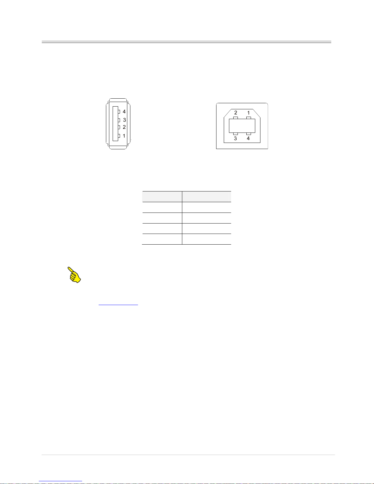
7.2 Universal Serial Bus (USB) port pin assignment
Connector type: Type A and B
USB A (Master) USB B (Slave)
Pin Function
1 VBUS
2 D3 D+
4 GND
Note: Master VBUS provides +5V max current 500mA. Slave VBUS is N/C.
For more information about USB, please visit the website:
www.usb.org
.
Page 51
Ver:1.1
s4 series user’s manual
46
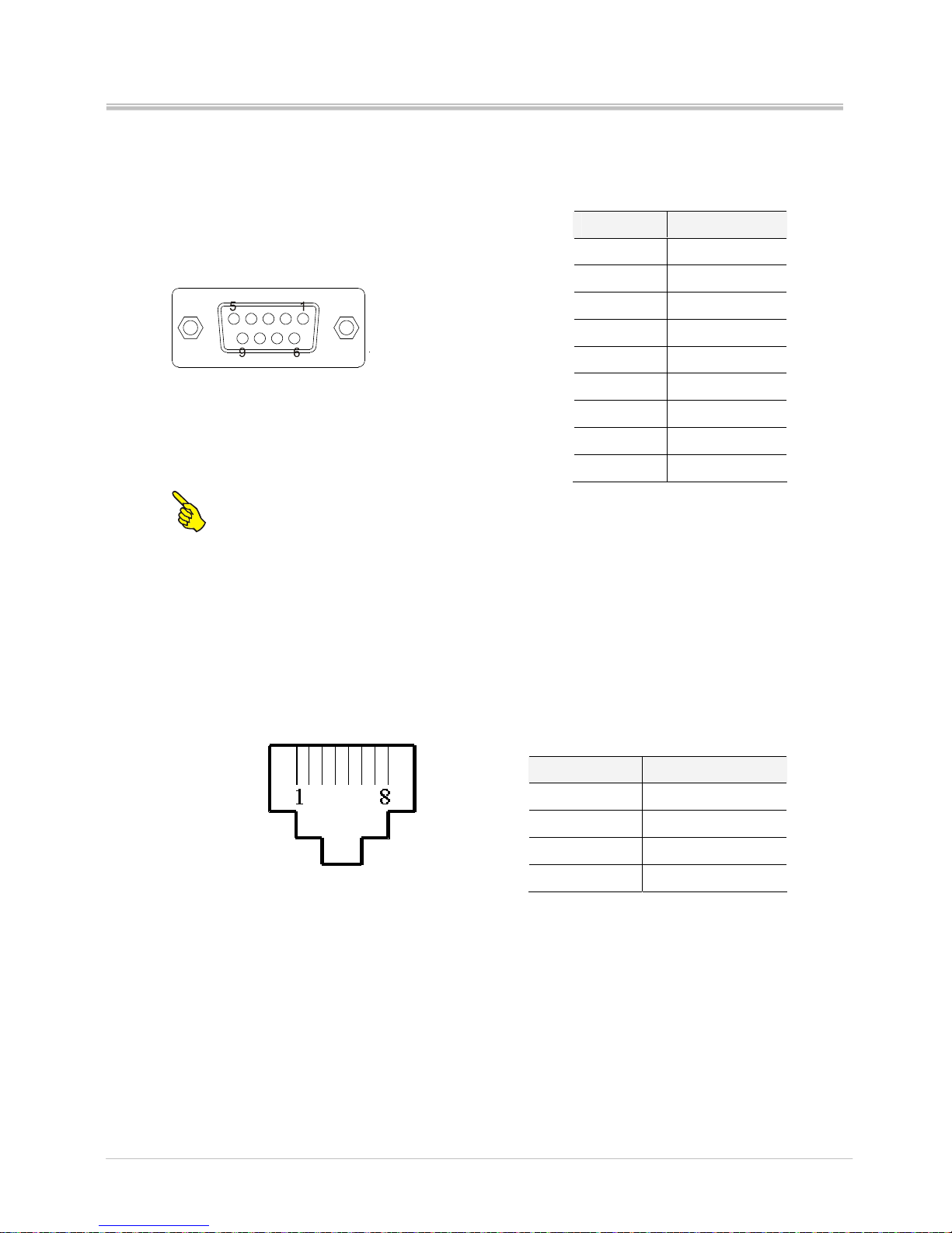
7.3 Serial port pin assignment
Note: Serial port provides +5V max current 500mAh
7.4 Ethernet module port pin assignment
Pin Printer side
1 N/C
2 TXD
3 RXD
4 DSR
5 GND
6 DTR
7 CTS
8 RTS
9 +5V
Pin Signal
1 Tx+
2 Tx3 Rx+
6 Rx-
 Loading...