

Page 1

MD2 Series Barcode Scanner
User Manual
Version: MD2_UM_EN_V3.1.6C
Page 2

i
Warning: Ensure that the optional DC adapter works at +5V,
especially for the RS-232 interface cable.
NOTICE:
1. All software, including firmware, furnished to the user is on a licensed basis.
2. The right is reserved to make changes to any software or product to improve reliability, function, or
design.
3. The material in this manual is subject to change without notice.
4. A standard packing includes a scanner, a PS2 cable and a CD (or a user manual). Accessories
include a stand, a RS-232 cable, a 5V adaptor and a USB cable.
Page 3

ii
Contents
Technical specifications ................................................................................................................................ 1
Default setting for each barcode.................................................................................................................. 2
Decode zone................................................................................................................................................... 3
Dimensions ..................................................................................................................................................... 4
Parts of the scanner ......................................................................................................................................5
Introduction to installation............................................................................................................................. 6
Scanning modes ............................................................................................................................................7
Programming instruction............................................................................................................................... 8
Interface selection..........................................................................................................................................9
Keyboard wedge .......................................................................................................................................... 10
RS-232 interface .......................................................................................................................................... 12
Operating in command mode..................................................................................................................... 12
Hand-held scan & some global settings ................................................................................................... 14
Indication ....................................................................................................................................................... 16
Auto-detection scan..................................................................................................................................... 17
UPC-A............................................................................................................................................................ 18
UPC-E............................................................................................................................................................ 19
EAN-13 ..........................................................................................................................................................20
EAN-8 ............................................................................................................................................................21
Code 39 ......................................................................................................................................................... 22
Interleaved 2 of 5 .........................................................................................................................................24
Industrial 2 of 5............................................................................................................................................. 25
Matrix 2 of 5 ..................................................................................................................................................26
Codabar......................................................................................................................................................... 27
Code 128....................................................................................................................................................... 28
Code 93 ......................................................................................................................................................... 29
Code 11 ......................................................................................................................................................... 30
MSI/Plessey.................................................................................................................................................. 31
UK/Plessey....................................................................................................................................................32
UCC/EAN 128 ..............................................................................................................................................33
China Post..................................................................................................................................................... 34
GS1 DataBar (GS1 DataBar Truncated) .................................................................................................. 35
GS1 DataBar Limited................................................................................................................................... 36
GS1 DataBar Expanded .............................................................................................................................37
PDF417 .........................................................................................................................................................38
MicroPDF417................................................................................................................................................39
China Finance ..............................................................................................................................................40
G1-G6 & FN1 substitution string setting................................................................................................... 42
G1-G4 string position & Code ID position ................................................................................................ 45
Page 4

iii
String transmission ...................................................................................................................................... 46
Test Chart...................................................................................................................................................... 48
Test Chart (Continued)................................................................................................................................ 49
Troubleshooting............................................................................................................................................ 50
Maintenance ................................................................................................................................................. 51
Assembling the stand .................................................................................................................................. 52
ASCII Table................................................................................................................................................... 53
Barcode representing control character ...................................................................................................54
Configuration alphanumeric entry barcode ..............................................................................................56
Page 5

1
Technical specifications
Table 1 Technical specifications
Input voltage 5 VDC ± 0.25V
Power 500 mW (Operating); 950 mW (Max.)
Current 100 mA (Operating); 190 mA (Max.)
Standby current <250μA
Laser 650nm laser diode
Laser safety EN60825-1, Class 1
Decoding rate 200 times/sec
Scanning angle ±60°, ±65°, ±42° (Skew, Pitch, Roll)
Min. element width 0.127mm (5mil) for Long-Range series; 0.076mm (3mil) for High-Density series
Decode capability
UPC-A, UPC-E, EAN-13, EAN-8, ISBN/ISSN, Code 39, Code 39 full ASCII, Code
32, Trioptic Code 39, Interleaved 2 of 5, Industrial 2 of 5, Matrix 2 of 5,
Codabar(NW7), Code 128, Code 93, Code 11(USD-8), MSI/Plessey, UK/Plessey,
UCC/EAN 128, China Post, China Finance, GS1 DataBar (formerly RSS) variants
Indicator Beeper, LED
Interface supported Keyboard wedge, RS-232, USB
Operating mode Hand-held, Auto-detection (Optional)
Dimensions Height × Width × Depth:9.5cm × 6.7cm × 15.4cm
Weight 148g, without cable
Cable Straight 2.0m
Connector type RJ-45 phone jack connector
Case material ABS + PC
Temperature 0° to 50°C (32° to 120°F), Operating; -40° to 60°C (-40° to 140°F), Storage
Humidity 5% to 95% (non-condensing)
Durability Multiple 4.0m (13.1 ft) drops to concrete
Programming method Manual (reading special barcode)
Program upgrade Online
Page 6

2
Default setting for each barcode
Table 2 Default setting for each barcode
Code type
Read
enable
Check digit
verification
Check digit
transmission
Min. code
length
Proprietary
code ID
AIM
code ID
UPC-A √ √ √ (12)2 A ]Em
UPC-E √ √ √ (8)2 D ]Em
EAN-13
√ √ √ (13)
2
A ]Em
EAN-8 √ √ √ (8)2 C ]Em
ISBN/ISSN1 √ √ √ (13)2 A ]Em
Code 39 √ - - 1 M ]Am
Interleaved 2 of 5 √ - - 6 I ]Im
Industrial 2 of 5 √ - - 4 H ]Im
Matrix 2 of 5 √ - - 6 X ]Im
Codabar √ - - 4 N ]Fm
Code 128 √ √ - 1 K ]Cm
Code 93 √ √ - 1 L ]Gm
Code 11 - √ - 4 V -
MSI/Plessey √ - - 4 O ]Mm
UK/Plessey √ √ - 1 U ]Mm
UCC/EAN 128 √ √ - 1 K ]Cm
China Post √ - - (11)2 T ]Im
China Finance √ - - (10)2 Y -
GS1 DataBar - - - (16)2 R ]em
GS1 DataBar Truncated3 - - - (16)2 R ]em
GS1 DataBar Limited - - - (16)2 R ]em
GS1 DataBar Expanded - - - 1 R ]em
PDF417 - - - 1 P ]Lm
MicroPDF417 - - - 1 P ]Lm
Note: 1The settings for ISBN/ISSN and EAN-13 must be the same.
2
Fixed-length barcodes.
3
The settings for GS1 DataBar Truncated and GS1 DataBar must be the same.
Page 7
3
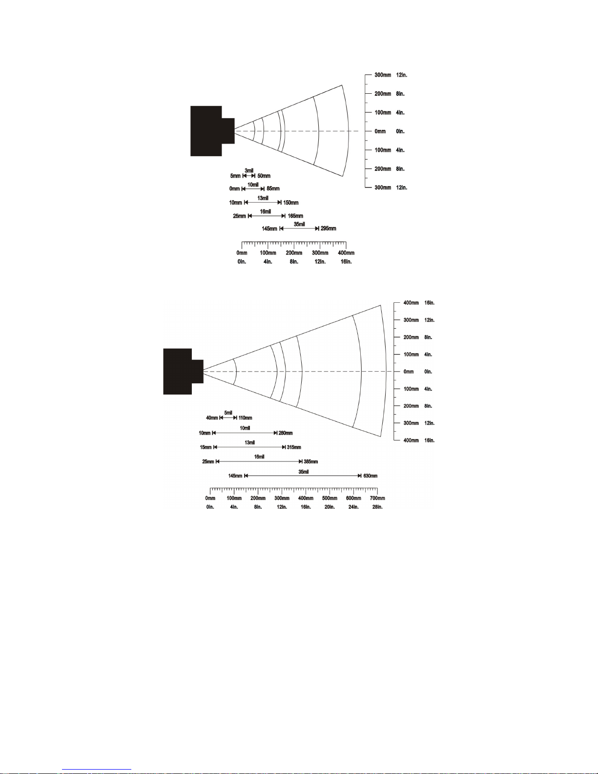
Decode zone
High-Density series
Long-Range series
Page 8
4
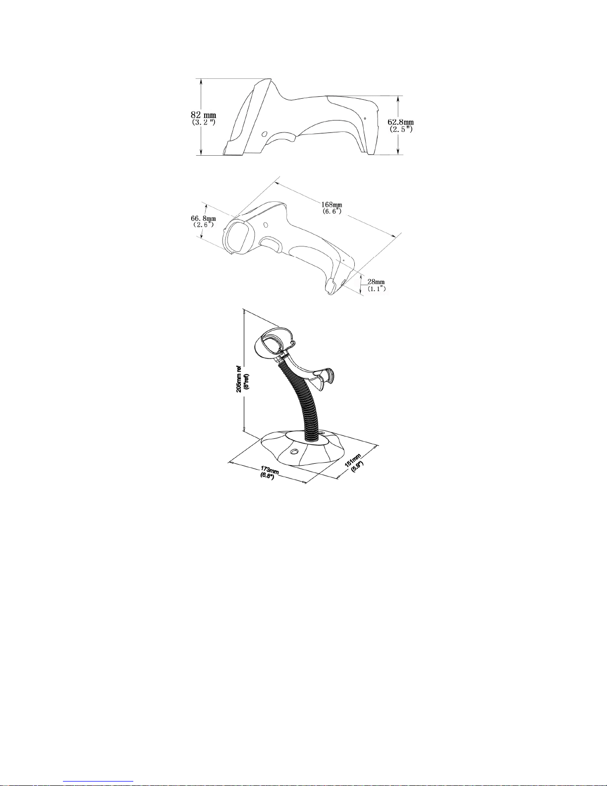
Dimensions
Page 9
5
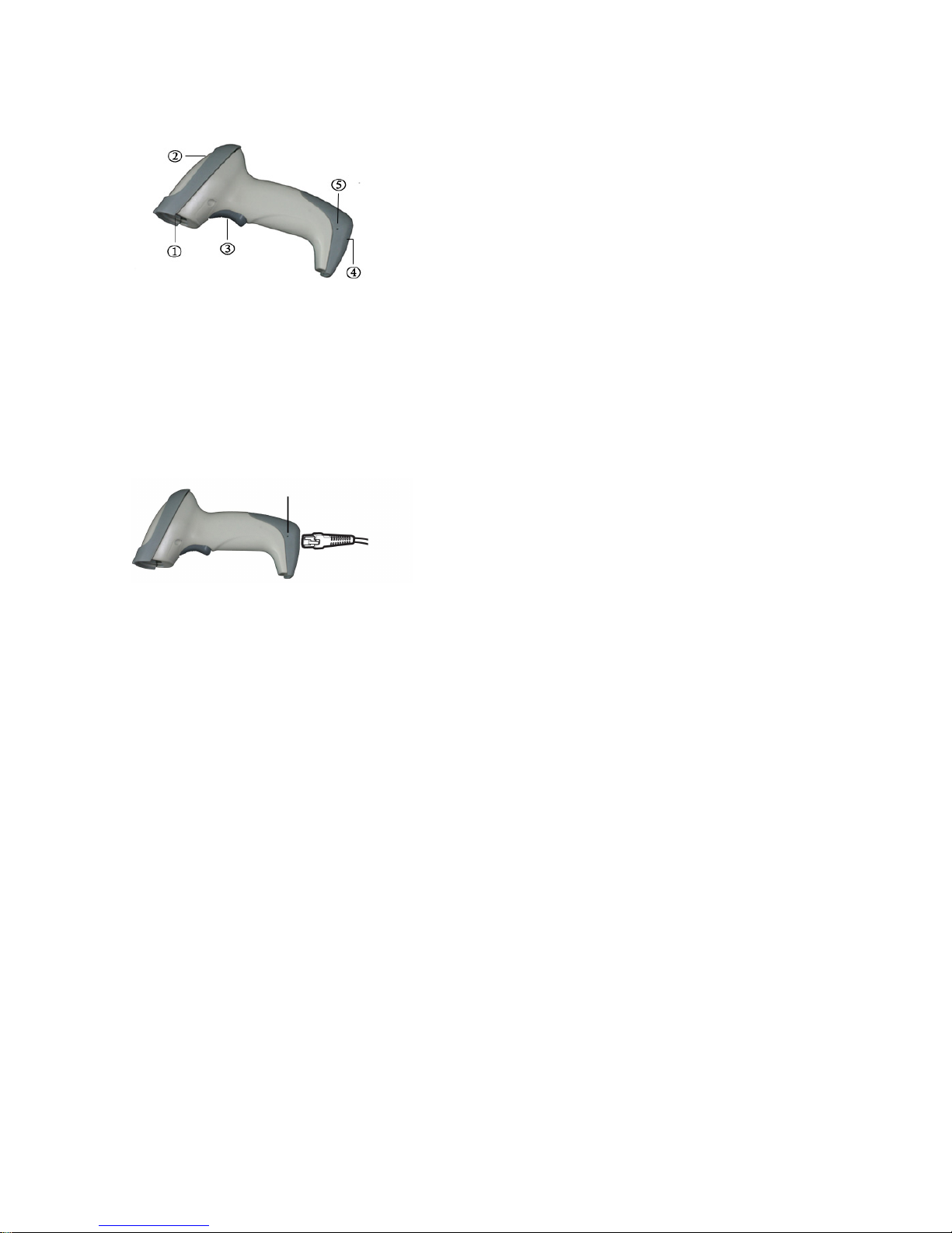
Parts of the scanner
Figure 1
① Exit window
② LED
③ Trigger
④ Cable interface port
⑤ Release-hole of the cable
Figure 2
Remove the interface cable:
1. Find the release-hole.
2. Insert a thin wire into the hole and pull out the cable gently.
Page 10
6
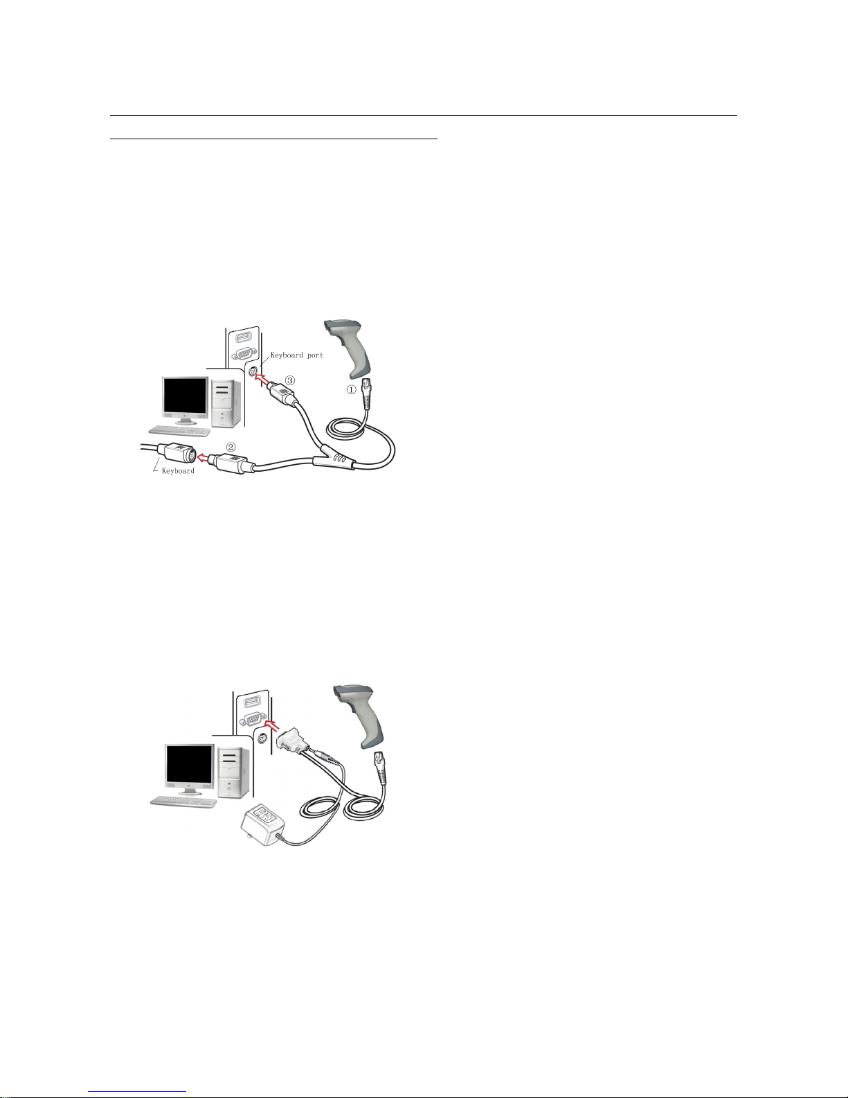
Introduction to installation
Note: If any of the below operation is incorrect, turn off the power immediately and check the scanner for
any improper connections. Go through all steps again.
Installation - keyboard wedge
1. Switch off the host and unplug the keyboard connector.
2. Attach the modular connector of the Y-cable to the cable interface port on the scanner.
3. Connect the round male DIN host connector of the Y-cable to the keyboard port on the host device.
4. Connect the round female DIN keyboard connector of the Y-cable to the keyboard.
5. Ensure that all connections are secure.
6. Switch on the host system.
Figure 3
Installation - RS-232
1. Connect the RS-232 interface cable to the bottom of the scanner.
2. Connect the other end of the interface cable to the serial port on the host. Tighten the two screws
to secure the connector to the port.
3. If the host does not have power supply (on PIN 9), connect the external power supply (DC adapter)
to the RS-232 cable.
Figure 4
Installation - USB
The scanner attaches directly to a USB host, and is powered by it. No additional power supply is
required.
1. Refer to Figure 4, connect the USB interface cable to the bottom of the scanner.
2. Plug the series A connector in the USB host, or an available port of the terminal.
3. Windows will automatically detect the USB device.
Page 11
7
Scanning modes
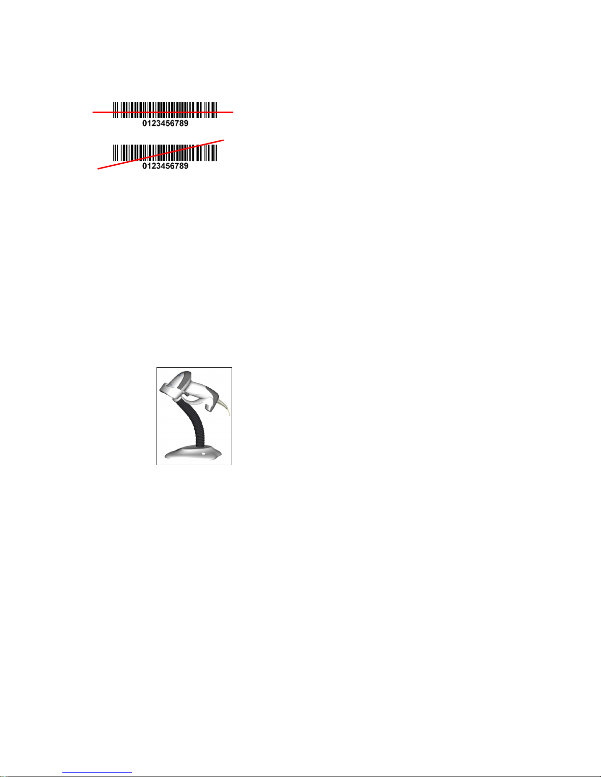
The scanner has two scanning modes: hand-held and auto-detection. When the scanner is scanning,
ensure the scan line crosses every bar and space of the symbol.
RIGHT
WRONG
Figure 5
The auto-detection scanning mode has two operating modes: in-stand and always ON. The following is
an introduction to in-stand auto-detection mode.
1. When the scanner is seated in the stand, the scanner operates in auto-detection mode (see Figure
6). When scanner is removed from the stand, it operates in its normal hand-held mode.
2. To scan a bar code, present the bar code and ensure the scan line crosses every bar and space of
the symbol.
3. Upon successful decode, the scanner beeps and the LED lights.
4. When the laser light is off, the present bar code must be removed to active next scanning.
Figure 6
Page 12
8
Programming instruction
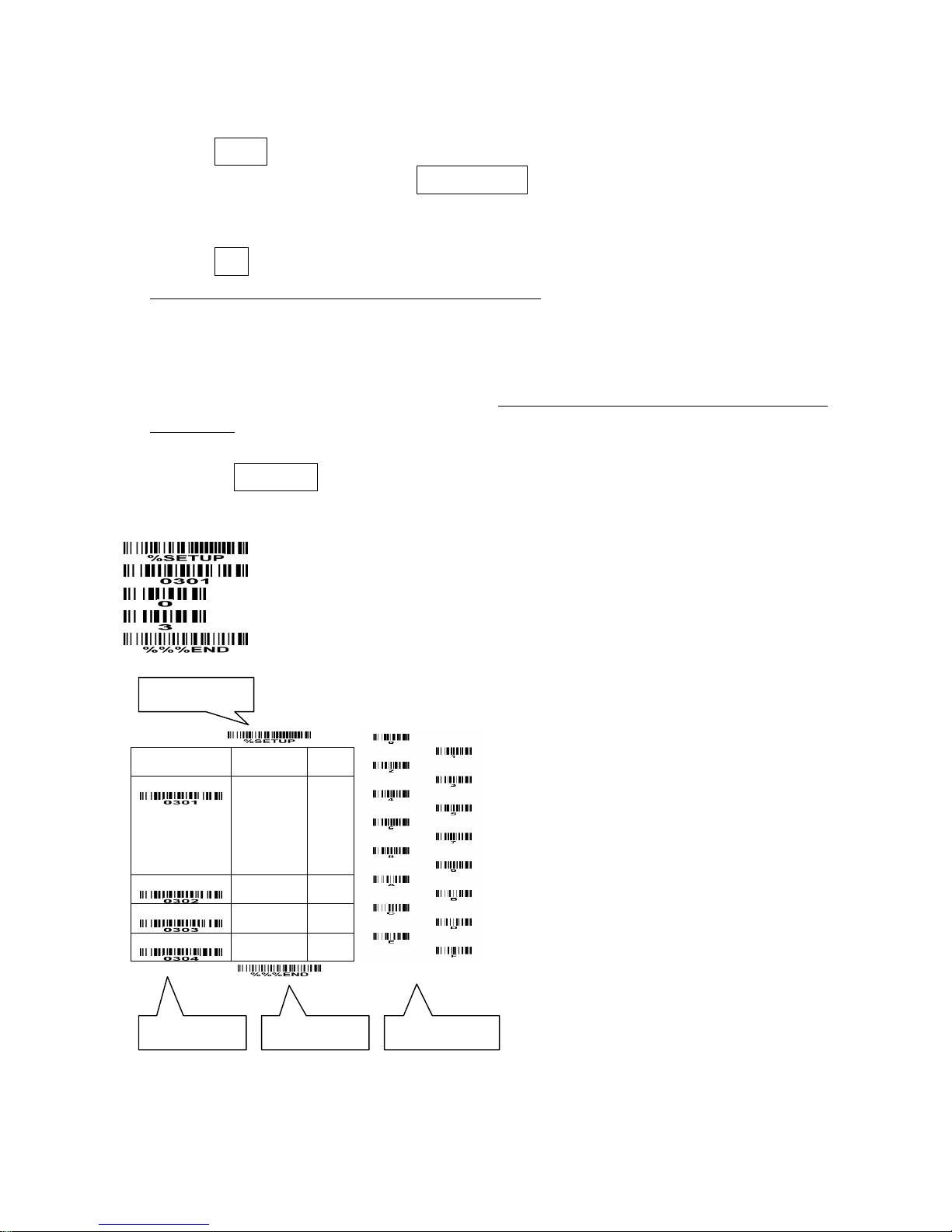
Refer to the next page, the steps of programming are:
1. Scan the SETUP bar code on the parameter setting part.
2. Enter the option mode by scanning the Option bar code.
3. To the right of the option barcode, the necessary alphanumeric inputs are listed. Scan these
alphanumeric entries.
4. Scan the END bar code, listed on the lower right hand corner of each parameter setting part.
5. Notes that only one parameter can be setup at each time.
6. During the process of programming, LED is lighting to indicate the programming correctness. LED
will go off if any incorrect programming operation performed.
7. After each successful programming, LED will go off and the scanner will beep twice.
8. Throughout the programming bar code menus, the factory default settings are indicated with
asterisks (*).
Example: to set Flow control to be XON/XOFF.
Steps: Scan the following barcodes in order.
SETUP
Option bar code Option
Alpha.
entry
Flow control
None
RTS/CTS
(Host: Low RTS)
RTS/CTS
(Host: High RTS)
XON/XOFF
ACK/NAK
00*
01
02
03
04
Inter-character delay
00-99 (ms)
00-99
00*
Block trans. delay
00-99 (10 ms) 00-99
00*
Response delay
00-99 (100 ms) 00-99
00*
END
Figure 7
SETUP bar code
Alpha. entries
Option bar code END bar code
Page 13
9
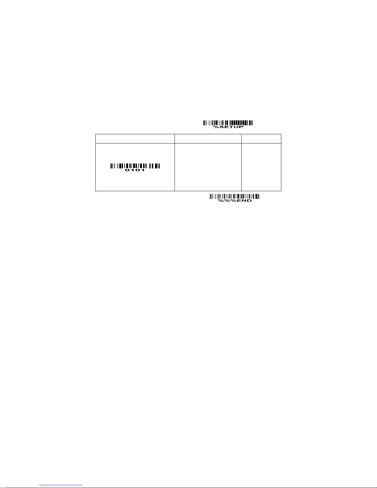
Interface selection
This scanner supports interfaces such as keyboard wedge, RS-232 serial wedge, and USB interface.
In most of the cases, simply selecting an appropriate cable provided by the manufacturer will work for a
specific interface.
Interface selection:
Auto detection-By setting this function, the scanner will automatically detect the keyboard wedge,
RS-232 or USB interface for user.
SETUP
Option bar code Option Alpha. entry
Interface selection
Auto detection (Keyboard
wedge /RS-232/USB)
Keyboard wedge
RS-232
USB
00*
01
02
03
END
Page 14

10
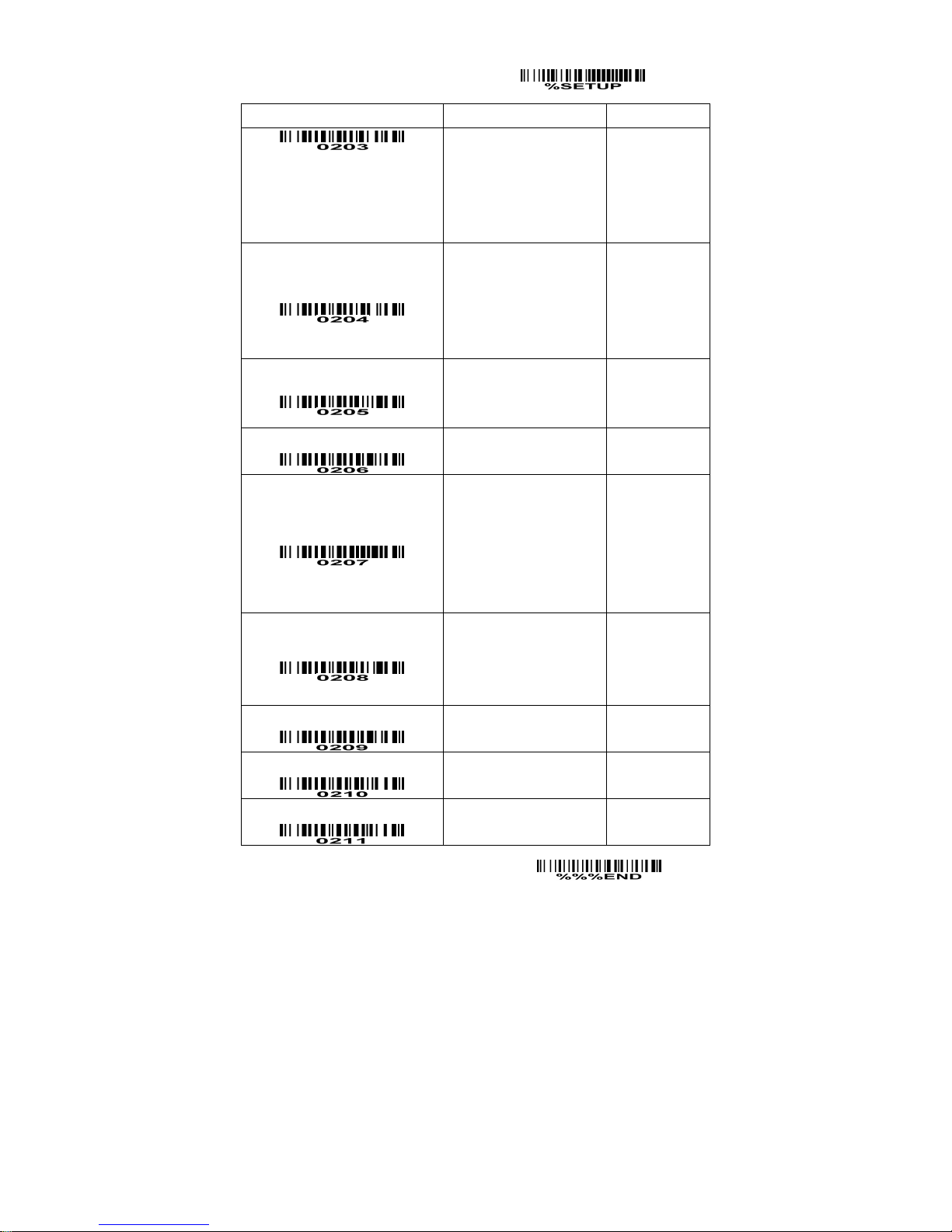
Keyboard wedge
Keyboard type: As a keyboard interface, the scanner supports most of the popular PCs and IBM
terminals.
Keyboard layout: The scanner supports different national keyboard layouts.
Clock period: According to the PS2 protocol, the clock is provided by the device, e.g. keyboard or
scanner, with the period between 60us to 100us.
Delay-after-compound-key: In some rare occasions, machine with low speed PS2 communication port
would require a free time gap following the press/release of the compound key (Shift, Ctrl or Alt).
Numeric key:
Alphabetic key- the scanner will output code result as alphabetic key.
Numeric key- the scanner will output code result as pressing numeric keypad ( ‘0’, ‘1’, ‘2’, ‘3’, ‘4’, ‘5’, ‘6’,
‘7’, ‘8’, ‘9’, ‘.’, ‘+’, ‘-‘, ‘/’, ‘*’ only).
Alt+ keypad- the scanner will output code result as pressing Alt+ numeric key (on keypad). Note that
the Num Lock control key must be ON. This setting can be specially adapted for use with different
national keyboard layout.
Power-on simulation: All of the PCs check the keyboard status during power-on self test. It simulates
keyboard timing and passes keyboard present status to the PC during power-on.
Inter-character delay: This delay is inserted after each data character transmitted.
Inter-byte delay: This delay is inserted after each byte transmitted. Normally a character is comprised
of three or above bytes.
Block trans. delay: It is a delay timer between barcode data output. This feature is used to transfer
continually with shorter barcode data.
Caps Lock status: By selecting
Caps Lock “ON”
or
Caps Lock “OFF”
, the scanner will output data string
based on the information on the Caps Lock status.
Caps Lock override: If this function is enabled, on AT or AT notebook hosts, the keyboard ignores the
state of the Caps Lock key. Therefore, an ‘A’ in the bar code is sent as an ‘A’ no matter what the state
of the keyboard’s Caps Lock key.
SETUP
Option bar code Option Alpha. entry
Keyboard type
IBM AT, PS/2
Apple Mac compatibles
Reserved
00*
01
02
Keyboard layout
USA
Turkish F
Turkish Q
French
Italian
Spanish
Slovak
00*
01
02
03
04
05
06
Clock period 60us 00
Page 15
11
SETUP
Option bar code Option Alpha. entry
70us
80us
90us
100us
200us
01
02*
03
04
05
Delay-after-compound-key
0ms
10ms
20ms
40ms
80ms
00*
01
02
03
04
Numeric key
Alphabetic key
Numeric keypad
Alt+ keypad
00*
01
02
Power-on simulation
Disable
Enable
00*
01
Inter-character delay
0ms
5ms
10ms
20ms
40ms
80ms
00*
01
02
03
04
05
Inter-byte delay
1ms
2ms
4ms
8ms
00*
01
02
03
Caps Lock status
OFF
ON
00*
01
Caps Lock override
Disable
Enable
00*
01
Reserved
END
Page 16

12
RS-232 interface
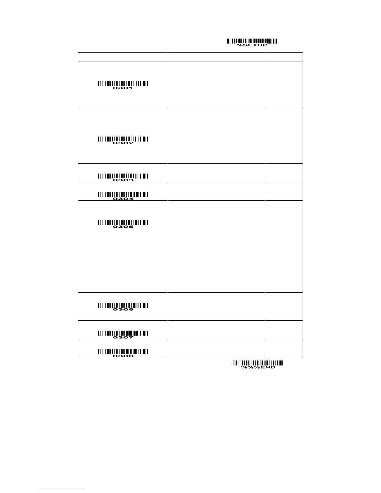
Flow control:
None-The communication only uses TxD and RxD signals without any hardware or software
handshaking protocol.
RTS/CTS-If the scanner wants to send the barcode data to host computer, it will issue the RTS signal
first, wait for the CTS signal from the host computer, and then perform the normal data communication.
If there is no replied CTS signal from the host computer after the timeout duration, the scanner will issue
an error indication. By setting (Host idle: Low RTS) or (Host idle: High RTS), the scanner can be set to
match the Serial Host RTS line.
XON/XOFF-An XOFF character turns the scanner transmission off until the scanner receives an XON
character.
ACK/NAK-After transmitting data, the scanner expects either an ACK (acknowledge) or NAK (not
acknowledge) response from the host. When a NAK is received, the scanner transmits the same data
again and waits for either an ACK or NAK. After three unsuccessful attempts to send data when NAKs
are received, the scanner issues an error indication and discards the data.
Inter-character delay: Refer to Inter-character delay of Keyboard wedge.
Response delay: This delay is used for serial communication of the scanner when it waits for a
handshaking acknowledgment from the host.
Operating in command mode
The scanner can operate in command mode. Commands, data and messages are sent by UART.
Commands from the Host, e.g. a PC:
1) Start Command: “0x54” (T)
Once the scanner receives 1-byte data “0x54”, it will be triggered to start barcode scanning.
2) Stop Command: “0x50” (P)
Once the scanner receives 1-byte data “0x50”, it will stop the current barcode scanning.
3) Reset Command: “0x52” (R)
Once the scanner receives 1-byte data “0x52”, it will switch off the power and then switch on the
power.
Returning message from the scanner:
1) A successful decode
Once the scanner successfully decoded a barcode, the scanner will stop scanning and returns
the barcode data to the Host.
2) Not a successful decode
Once the scanner failed to decode a barcode while receiving a Stop Command, the scanner will
stop scanning and returns a message to the Host. The message is set as “0x25, 0x25, 0x4E,
0x6F, 0x52, 0x65, 0x61, 0x64” (%%NoRead).
Page 17
13
SETUP
Option bar code Option Alpha. entry
Flow control
None
RTS/CTS (Host idle: Low RTS)
RTS/CTS (Host idle: High RTS)
XON/XOFF
ACK/NAK
00*
01
02
03
04
Inter-character delay
0ms
5ms
10ms
20ms
40ms
80ms
00*
01
02
03
04
05
Reserved
Response delay
00-99 (100ms)
00-99
00*
Baud rate
300
600
1200
2400
4800
9600
19200
38400
57600
115200
00
01
02
03
04
05*
06
07
08
09
Parity
None
Odd
Even
00*
01
02
Data bit
8 bits
7 bits
00*
01
Stop bit
One bit
Two bits
00*
01
END
Page 18

14
Hand-held scan & some global settings
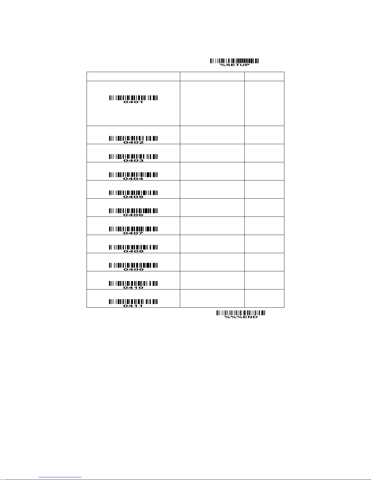
Scanning mode:
Good-read off-The trigger button must be pressed once to activate scanning. The light source of
scanner stops scanning when there is a successful reading or no code is decoded after the Stand-by
duration elapsed.
Momentary-The trigger button acts as a switch. Press button to activate scanning and release button to
stop scanning. The light source of scanner stops scanning when there is a successful reading or no
code is decoded after the Stand-by duration elapsed.
Alternate-The trigger button acts as a toggle switch. Press button to activate or stop scanning.
Continue-The scanner always keeps scanning, and it does not matter when the trigger button is pressed
or duration is elapsed.
Timeout off-The trigger button must be pressed once to activate scanning. The light source of scanner
stops scanning when no code is successful decoded after the Stand-by duration elapsed.
Same barcode delay time: If a barcode has been scanned and output once successfully, the laser beam
must be off or moved away from the barcode beyond delay time to active scanning the same barcode.
When this feature is set to be “0xFF”, then the delay time is indefinite.
Double confirm: If it is enabled, the scanner will require a several times of same-decoded-data to confirm
a valid reading.
Global Max./Min. code length: These two lengths are defined as the valid range of decoded barcode
data length. Make sure that the minimum length setting is no greater than the maximum length setting,
or otherwise the labels of the symbology will not be readable. In particular, the same value can be set
for both minimum and maximum reading length to force the fixed length barcode decoded.
Notes:
1. Please set the max./min. length for individual barcode in later sections, if special demand is
requested.
2. The number of check digits is included in max./min. code length.
3. These two settings have no effect on the symbologies with fixed-length, e.g. UPC-A, UPC-E, EAN-13,
EAN-8 and China Post.
Global G1-G6 string selection: The scanner offer one or two string group for ALL symbologies. By
setting one or two digits to indicate which string group you want to apply. You may refer to the chapters
of “String setting” and “String position & Number of truncated leading/ending character”.
Example: Group 1 → set 01 or 10. Group 2 and 4 → set 24 or 42.
All valid settings include 00, 01, 02, 03, 04, 05, 06, 10, 11, 12, 13, 14, 15, 16, 20, 21, 22, 23, 24, 25, 26,
30, 31, 32, 33, 34, 35, 36, 40, 41, 42, 43, 44, 45, 46, 50, 51, 52, 53, 54, 55, 56, 60, 61, 62, 63, 64, 65 and
66.
Element amendment: If it is enabled, the scanner can read the barcode comprised with bars and spaces
in different scale.
Printable character only: If it is enabled, the scanner will output the printable characters only, i.e. in
ASCII from 20H to 7EH.
Page 19
15
Decoder optimization: If it is enabled, the scanner will optimize the decoder with error correction. This
function is not effective for all types of barcodes.
SETUP
Option bar code Option Alpha. entry
Scanning mode
Good-read off
Momentary
Alternate
Continue
Timeout off
00
01*
02
03
04
Standby duration
01-99 (second)
01-99
04*
Same barcode delay time
00-FF
16
(50ms)
00-FF16
08*
Double confirm
00-09
(00: no )
00-09
00*
Global max. code length
04-99
04-99
99*
Global min. code length
01-99
01-99
04*
Global G1-G6 string selection
00-66
00-66
00*
Element amendment
Disable
Enable
00
01*
Printable character only
Disable
Enable
00*
01
Decoder optimization
Disable
Enable
00
01*
Reserved
END
Page 20
16
Indication
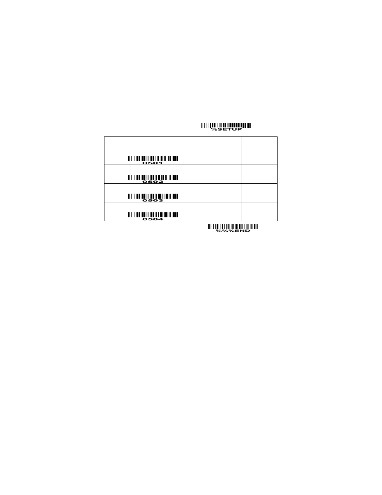
Power on alert: After power-on the scanner will generate an alert signal to indicate a successful self-test.
LED indication: After each successful reading, the LED above the scanner will light up to indicate a good
barcode reading.
Beeper indication: After each successful reading, the scanner will beep to indicate a good barcode
reading, and its beep tone duration is adjustable.
Beep tone duration: This parameter can be adjusted for a good reading upon favorite usage.
SETUP
Option bar code Option Alpha. entry
Power on alert
Disable
Enable
00
01*
LED indication
Disable
Enable
00
01*
Beeper indication
Disable
Enable
00
01*
Beep tone duration
01-09 (10ms ) 01-09
05*
END
Page 21
17
Auto-detection scan
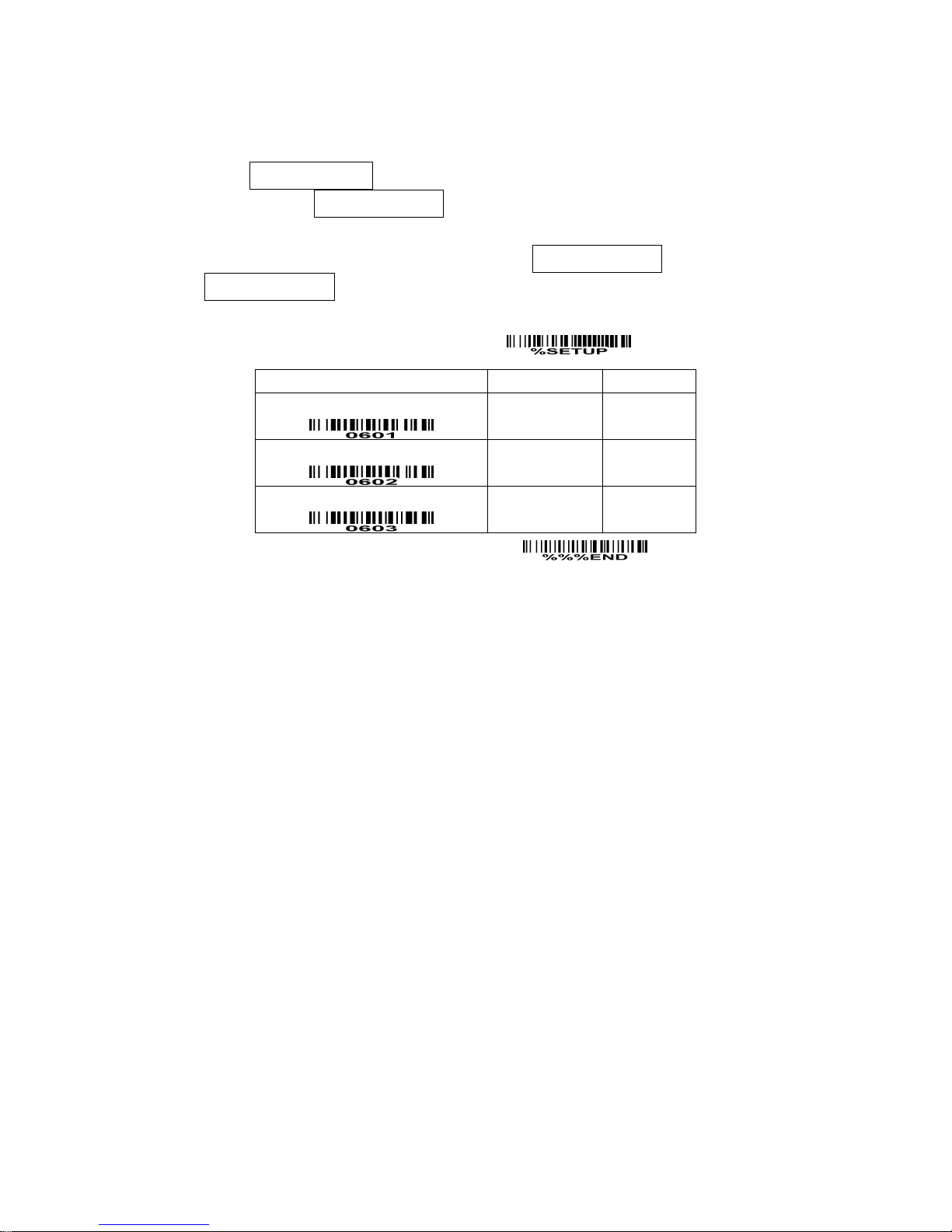
Auto-detect sensor: By setting Enable, the scanner will start operating if any nearby object has been
detected. The laser light of scanner stops scanning when there is a successful reading or no code is
decoded after the Stand-by duration elapsed. Once the laser light stops scanning, the present object
must be removed to enable Auto-detect sensor.
Operating mode:
In stand-The scanner must be placed in the stand to enable Auto-detect sensor.
Always ON-Auto-detect sensor is enabled regardless of the placement of the scanner.
SETUP
Option bar code Option Alpha. entry
Auto-detect sensor
Disable
Enable
00
01*
Operation mode
In stand
Always ON
00*
01
Stand-by duration
00-99 (second) 00-99
04*
END
Page 22
18
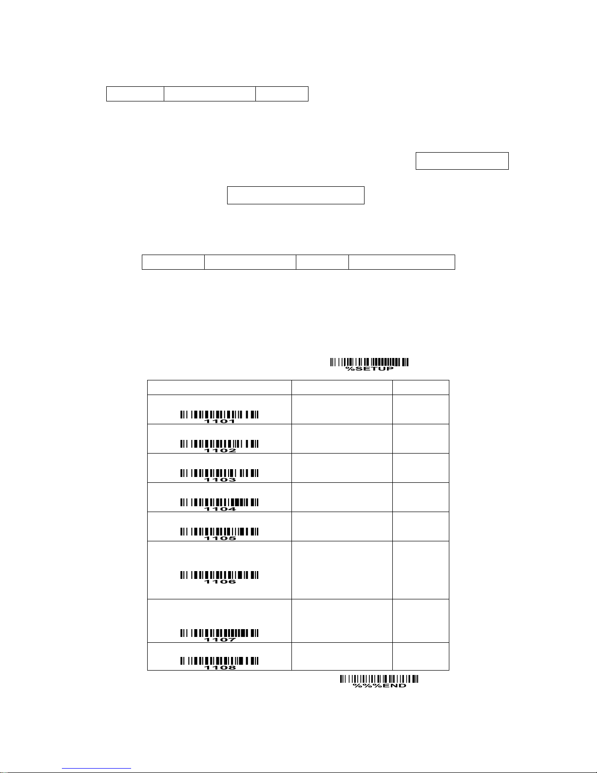
UPC-A
Read: Format
Leading zero Data digits (11 digits) Check digit
Check digit verification: The check digit is optional.
Check digit trans.: By setting Enable, check digit will be transmitted.
Code ID setting: Code ID is a one-or-two-character string used to represent the symbol upon a
succeeding reading. If you want application to transmit Code ID, you must set Code ID transmission to
be enabled. Refer to the chapter of String transmission.
Insertion group selection: Refer to Global insertion group selection of the chapter of Hand-held scan &
some global settings.
Supplement digits: The Supplement digits barcode is the supplemental 2 or 5 characters.
Format
Leading zero Data digits (11 digits) Check digit Supplement digits 2 or 5
Truncation/Expansion:
Truncate leading zeros- The leading “0” digits of UPC-A data characters can be truncated when the
feature is enabled.
Expand to EAN-13- It extends to 13-digits with a “0” leading digit when the feature is enabled.
SETUP
Option bar code Option Alpha. entry
Read
Disable
Enable
00
01*
Check digit verification
Disable
Enable
00
01*
Check digit trans.
Disable
Enable
00
01*
Code ID setting
00-FF
16
(ASCII)
00-FF16
<A>*
Insert group selection
00-66
00-66
00*
Supplement digits
None
2 digits
5 digits
2 or 5 digits
00*
01
02
03
Truncation/Expansion
None
Truncate leading zeros
Expand to EAN-13
00*
01
02
Reserved
END
Page 23
19
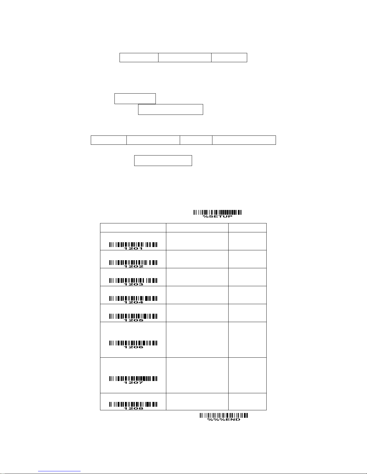
UPC-E
Read: Format
Leading zero Data digits (6 digits) Check digits
Check digit verification: The check digit is optional and made as the sum of the numerical value of the
data digits.
Check digit trans.: By setting Enable, check digit will be transmitted.
Code ID setting: Refer to Code ID setting of UPC-A.
Insertion group selection: Refer to Insertion group selection of UPC-A.
Supplement digits:
Format
Leading zero Data digits (6 digits) Check digit Supplement digits 2 or 5
Truncation/Expansion:
Truncate leading zeros- Refer to Truncation/Expansion of UPC-A.
Expand to EAN-13- It extends to 13-digits with “0” digits when the feature is set to be enabled.
Example: Barcode “0123654”,
Output: “0012360000057”.
Expand to UPC-A- It extends to 12-digits when the feature is set to be enabled.
SETUP
Option bar code Option Alpha. entry
Read
Disable
Enable
00
01*
Check digit verification
Disable
Enable
00
01*
Check digit trans.
Disable
Enable
00
01*
Code ID setting
00-FF
16
(ASCII)
00-FF16
<D>*
Insert group selection
00-66
00-66
00*
Supplement digits
None
2 digits
5 digits
2 or 5 digits
00*
01
02
03
Truncation/Expansion
None
Truncate leading zeros
Expand to EAN-13
Expand to UPC-A
00*
01
02
03
Reserved
END
Page 24
20
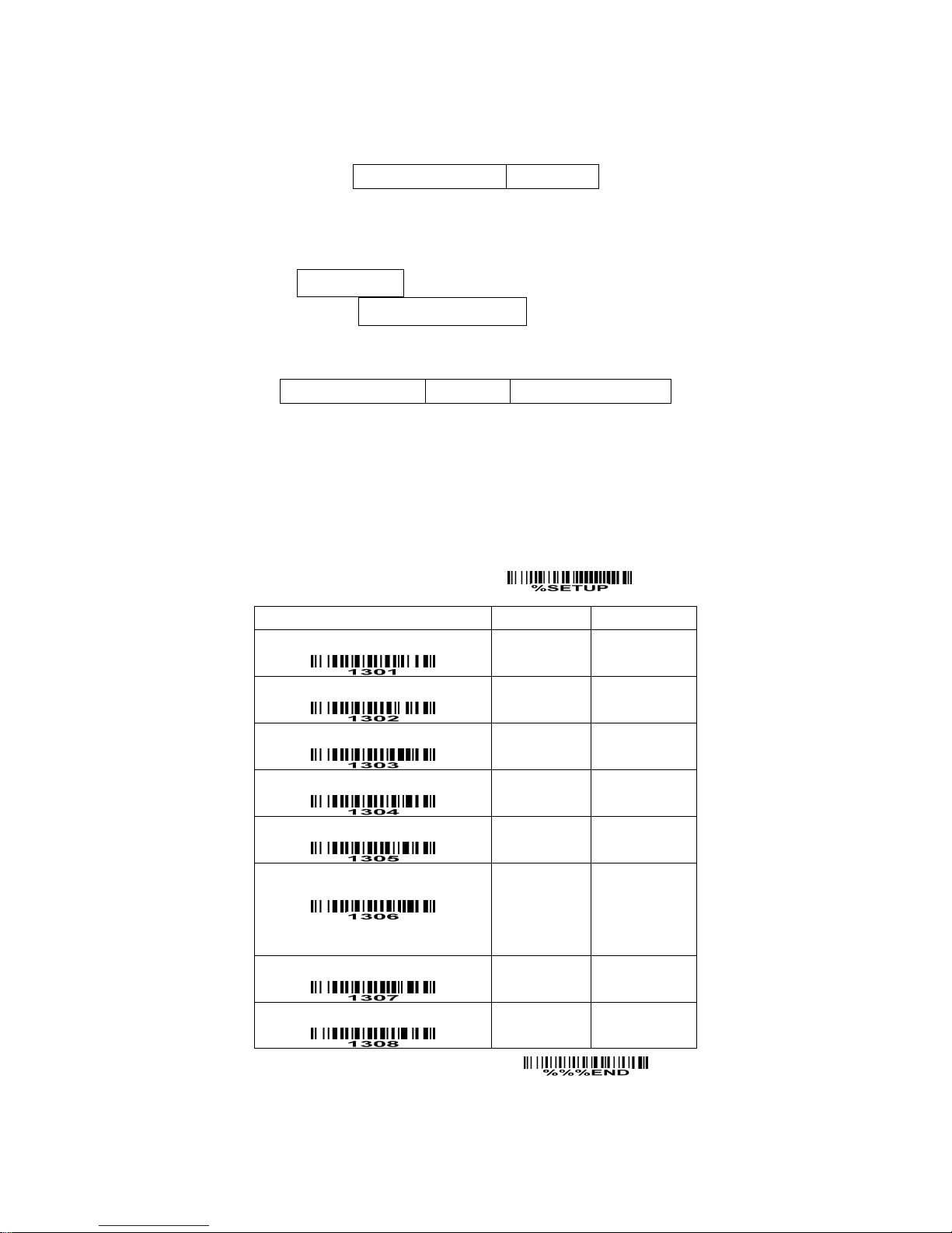
EAN-13
Read:
Format
Data digits (12 digits) Check digit
Check digit verification: The check digit is optional and made as the sum of the numerical value of the
data digits.
Check digit transmission: By setting Enable, check digit will be transmitted.
Code ID setting: Refer to Code ID setting of UPC-A.
Insertion group selection: Refer to Insertion group selection of UPC-A.
Supplement digits:
Format
Data digits (12 digits) Check digit Supplement digits 2 or 5
ISBN/ISSN: The ISBN (International Standard Book Number) and ISSN (International Standard Serial
Number) are two kinds of barcode for books and magazines. The ISBN is 10 digits with leading “978”
and the ISSN is 8 digits with leading “977” of the EAN-13 symbology.
Example:
Barcode “9780194315104”, Output: “019431510X”.
Barcode “9771005180004”, Output: “10051805”.
SETUP
Option bar code Option Alpha. entry
Read
Disable
Enable
00
01*
Check digit verification
Disable
Enable
00
01*
Check digit transmission
Disable
Enable
00
01*
Code ID setting
00-FF
16
(ASCII)
00-FF16
<A>*
Insert group selection
00-66
00-66
00*
Supplement digits
None
2 digits
5 digits
2 or 5 digits
00*
01
02
03
ISBN/ISSN conversion
Disable
Enable
00*
01
Reserved
END
Page 25
21
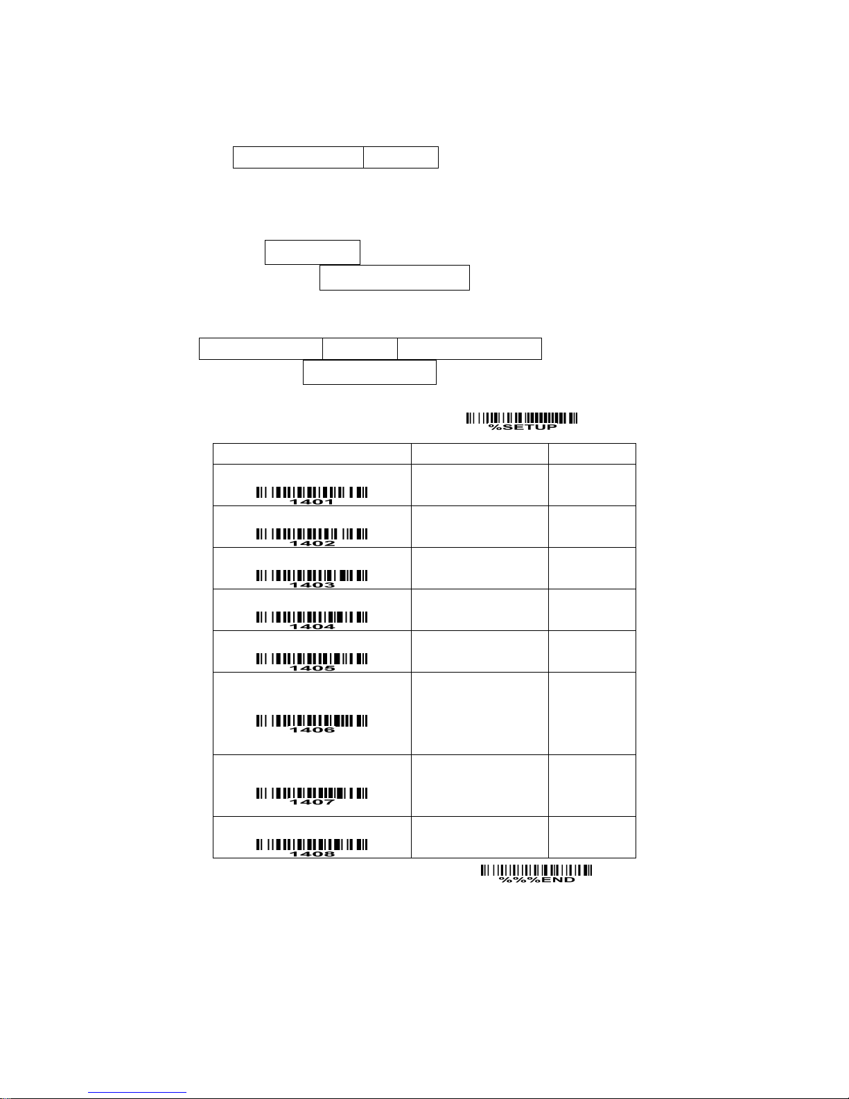
EAN-8
Read:
Format
Data digits (7 digits) Check digit
Check digit verification: The check digit is optional and made as the sum of the numerical value of the
data digits.
Check digit trans.: By setting Enable, check digit will be transmitted.
Code ID setting: Refer to Code ID setting of UPC-A.
Insertion group selection: Refer to Insertion group selection of UPC-A.
Supplement digits:
Format
Data digits (7 digits) Check digit Supplement Digits 2 or 5
Truncation/Expansion: Refer to Truncation/Expansion of UPC-A.
SETUP
Option bar code Option Alpha. entry
Read
Disable
Enable
00
01*
Check digit verification
Disable
Enable
00
01*
Check digit trans.
Disable
Enable
00
01*
Code ID setting
00-FF
16
(ASCII)
00-FF16
<A>*
Insert group selection
00-66
00-66
00*
Supplement digits
None
2 digits
5 digits
2 or 5 digits
00*
01
02
03
Truncation/Expansion
None
Truncate leading zero
Expand to EAN-13
00*
01
02
Reserved
END
Page 26

22
Code 39
Read:
Format
⋆ Data digits (variable) Check digit (optional) ⋆
Check digit verification: The check digit is optional and made as the sum module 43 of the numerical
value of the data digits.
Check digit transmission: By setting Enable, check digit will be transmitted.
Max./Min. code length: Each symbology has own max./min. code length. If both setting of max./min.
code length are “00”s, the setting of global max./min. code length is effective. The length is defined as
to the actual barcode data length to be sent. Label with length exceeds these limits will be rejected.
Make sure that the minimum length setting is no greater than the maximum length setting, or otherwise
all the labels of the symbology will not be readable. In particular, you can see the same value for both
minimum and maximum reading length to force the fixed length barcode decoded.
Code ID setting: Refer to Code ID setting of UPC-A.
Insertion group selection: Refer to Insertion group selection of UPC-A.
Start/End transmission: The start and end characters of Code 39 are “⋆”s. You can transmit all data
digits including two “⋆”s.
“⋆” as data character: By setting Enable, “⋆” can be recognized as data character.
Convert Code 39 to Code 32: Code 32 is a variant of Code 39 used by the Italian pharmaceutical
industry. Note that Code 39 must be enabled in order for this parameter to function.
Format of Code 32
“A” (optional) Data digits (8 digits) Check digit
Code 32 Prefix “A” transmission: By setting Enable, the prefix character “A” can be added to all Code 32
barcodes.
Trioptic Code 39 read: Trioptic Code 39 is a variant of Code 39 used in the marking of magnetic tapes
and computer cartridges. Trioptic Code 39 symbols always contain six characters.
Format
$ Data digits (6 digits) $
Trioptic Code 39 Start/End transmission: The start and end characters of Trioptic Code 39 are “$”s.
You can transmit all data digits including two “$”s.
Page 27

23
SETUP
Option bar code Option Alpha. entry
Read
Disable
Enable
00
01*
Check digit verification
Disable
Enable
00*
01
Check digit transmission
Disable
Enable
00*
01
Max. code length
00-99
00-99
00*
Min. code length
00-99
00-99
01*
Code ID setting
00-FF
16
(ASCII)
00-FF16
<M>*
Insert group selection
00-66
00-66
00*
Format
Standard
Full ASCII
00*
01
Start/End transmission
Disable
Enable
00*
01
“⋆” as data character
Disable
Enable
00*
01
Convert Code 39 to Code 32
Disable
Enable
00*
01
Code 32 Prefix “A” transmission
Disable
Enable
00*
01
Trioptic Code 39 read
Disable
Enable
00
01*
Trioptic Code 39 Start/End transmission
Disable
Enable
00*
01
END
Page 28
24
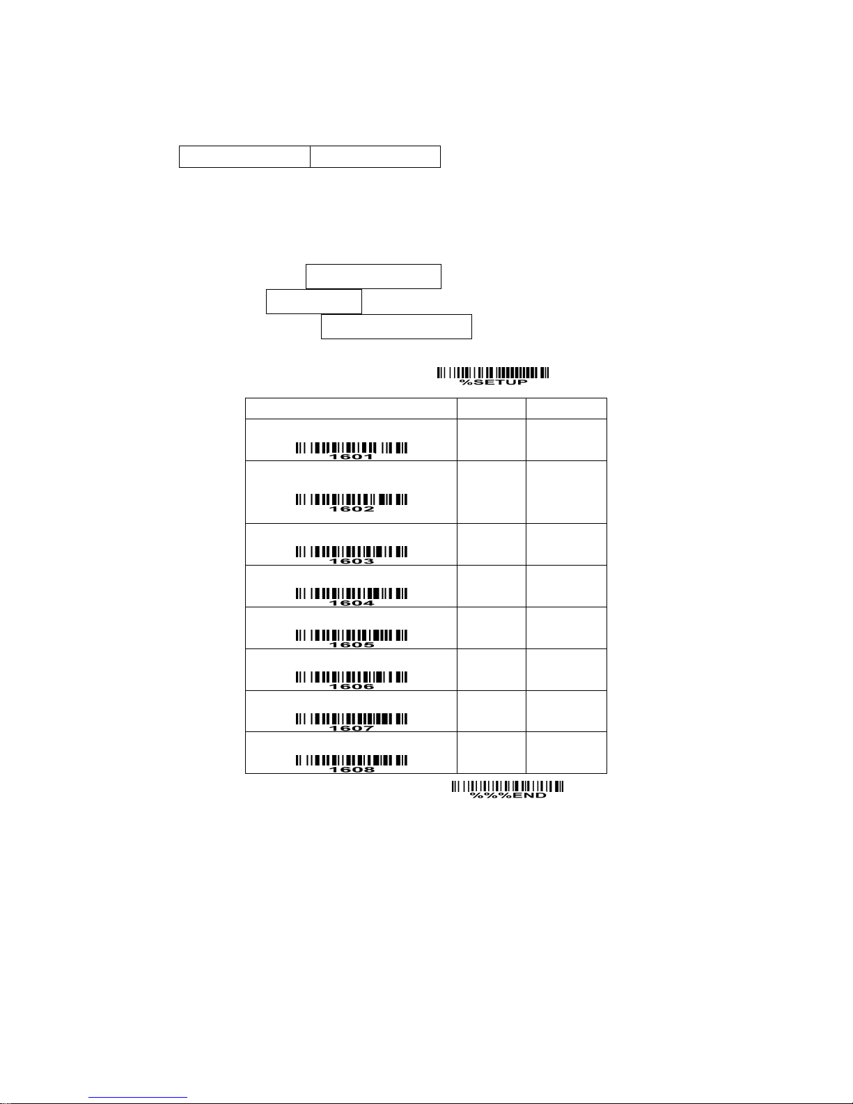
Interleaved 2 of 5
Read:
Format
Data digits (Variable) Check digit (optional)
Check digit verification: The check digit is made as the sum module 10 of the numerical values of all data
digits. There are two optional check digit algorithms: the specified Uniform Symbology Specification
(USS) and the Optical Product Code Council (OPCC).
Check digit transmission: By setting Enable, check digit will be transmitted.
Max./Min. code length: Refer to Max./Min. code length of Code 39.
Code ID setting: Refer to Code ID setting of UPC-A.
Insertion group selection: Refer to Insertion group selection of UPC-A.
SETUP
Option bar code Option Alpha. entry
Read
Disable
Enable
00
01*
Check digit verification
Disable
USS
OPCC
00*
01
02
Check digit transmission
Disable
Enable
00*
01
Max. code length
00-99
00-99
00*
Min. code length
00-99
00-99
06*
Code ID setting
00-FF
16
(ASCII)
00-FF16
<I>*
Insert group selection
00-66
00-66
00*
Reserved
END
Page 29
25
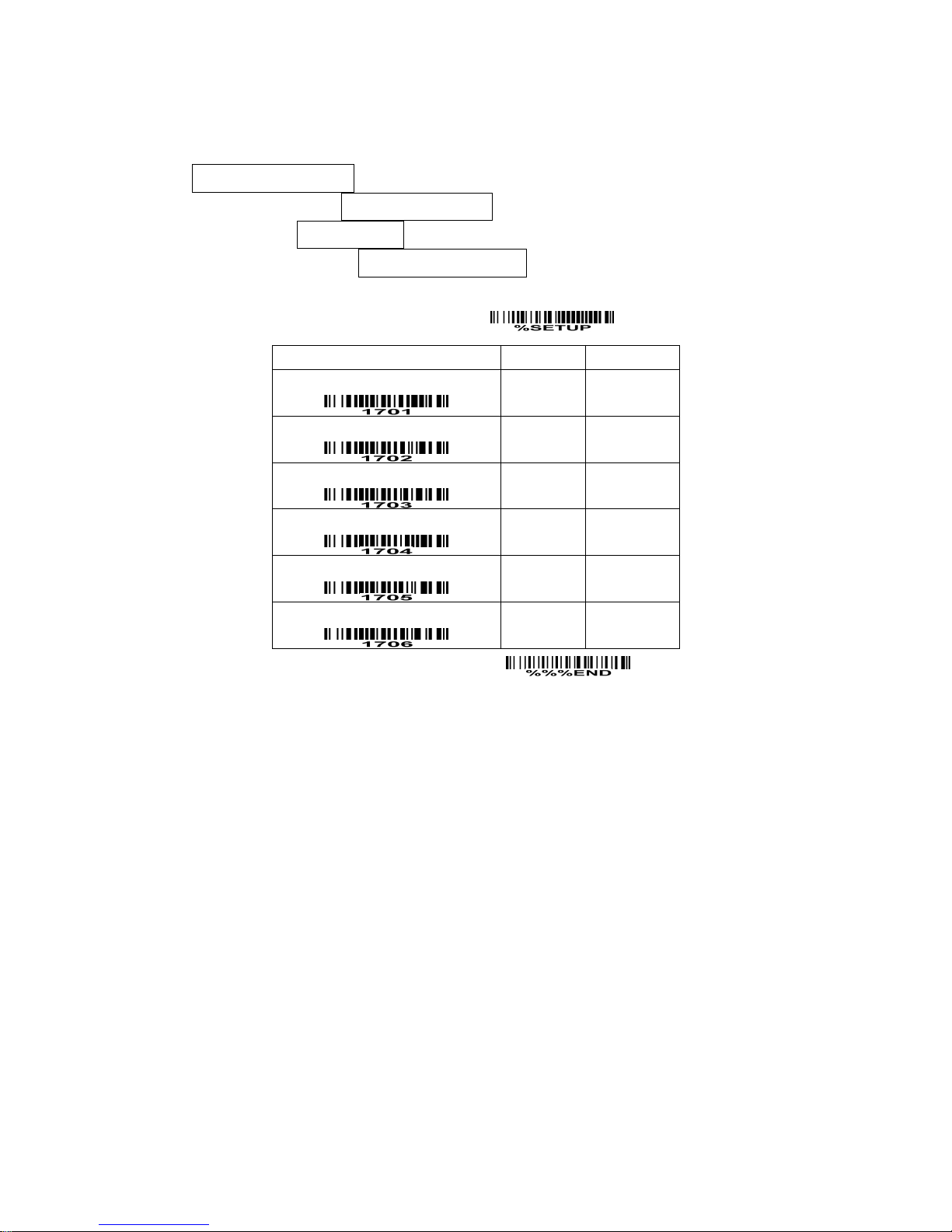
Industrial 2 of 5
Read:
Format
Data digits (variable)
Max./Min. code length: Refer to Max./Min. code length of Code 39.
Code ID setting: Refer to Code ID setting of UPC-A.
Insertion group selection: Refer to Insertion group selection of UPC-A.
SETUP
Option bar code Option Alpha. entry
Read
Disable
Enable
00
01*
Max. code length
00-99
00-99
00*
Min. code length
00-99
00-99
00*
Code ID setting
00-FF16
(ASCII)
00-FF16
<H>*
Insert group selection
00-66
00-66
00*
Reserved
END
Page 30
26
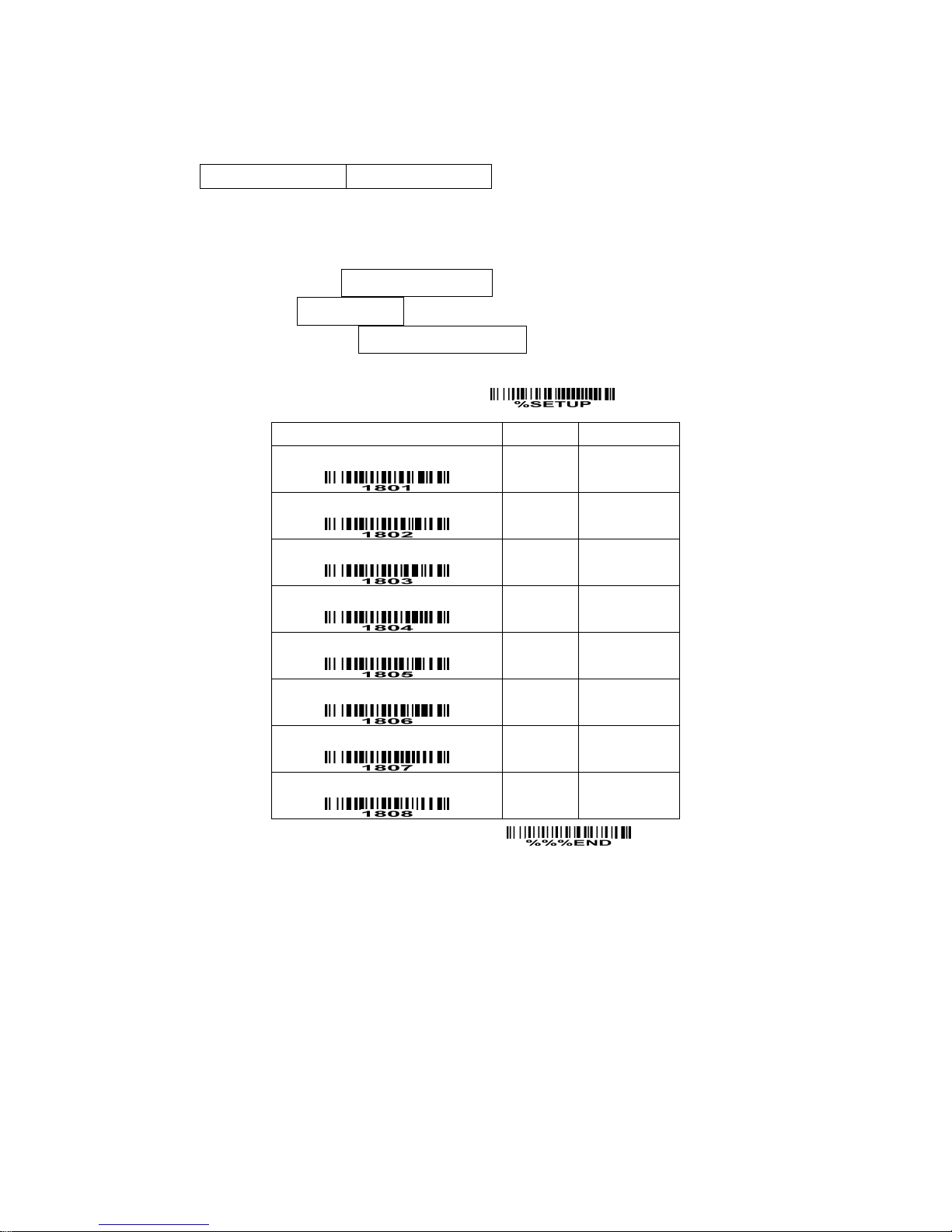
Matrix 2 of 5
Read:
Format
Data digits (variable) Check digit (optional)
Check digit verification: The check digit is made as the sum module 10 of the numerical values of all data
digits.
Check digit transmission: By setting Enable, check digit will be transmitted.
Max./Min. code length: Refer to Max./Min. code length of Code 39.
Code ID setting: Refer to Code ID setting of UPC-A.
Insertion group selection: Refer to Insertion group selection of UPC-A.
SETUP
Option bar code Option Alpha. entry
Read
Disable
Enable
00
01*
Check digit verification
Disable
Enable
00*
01
Check digit transmission
Disable
Enable
00*
01
Max. code length
00-99
00-99
00*
Min. code length
00-99
00-99
06*
Code ID setting
00-FF
16
(ASCII)
00-FF16
<X>*
Insert group selection
00-44
00-44
00*
Reserved
END
Page 31
27
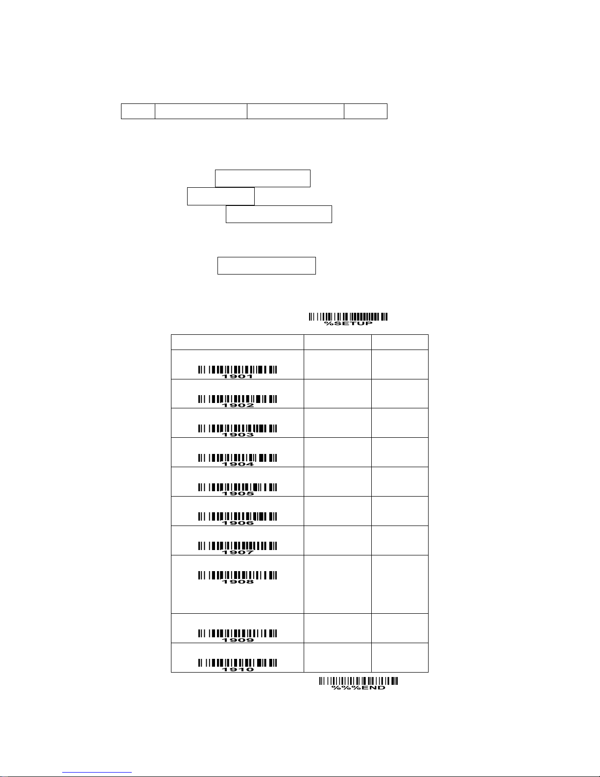
Codabar
Read:
Format
Start Data digits (variable) Check digit (optional) End
Check digit verification: The check digit is made as the sum module 16 of the numerical values of all data
digits.
Check digit transmission: By setting Enable, check digit will be transmitted.
Max./Min. code length: Refer to Max./Min. code length of Code 39.
Code ID setting: Refer to Code ID setting of UPC-A.
Insertion group selection: Refer to Insertion group selection of UPC-A.
Start/End type: Codabar has four pairs of Start/End pattern; you may select one pair to match your
application.
Start/End transmission: Refer to Start/End transmission of Code 39.
Start/End character equality: By setting Enable, the start and end character of a Codabar barcode must
be the same.
SETUP
Option bar code Option Alpha. entry
Read
Disable
Enable
00
01*
Check digit verification
Disable
Enable
00*
01
Check digit transmission
Disable
Enable
00*
01
Max. code length
00-99
00-99
00*
Min. code length
00-99
00-99
00*
Code ID setting
00-FF
16
(ASCII)
00-FF16
<N>*
Insert group selection
00-66
00-66
00*
Start/End type
ABCD/ABCD
abcd/abcd
ABCD/TN⋆E
abcd/tn⋆e
00*
01
02
03
Start/End transmission
Disable
Enable
00*
01
Start/End character equality
Disable
Enable
00*
01
END
Page 32
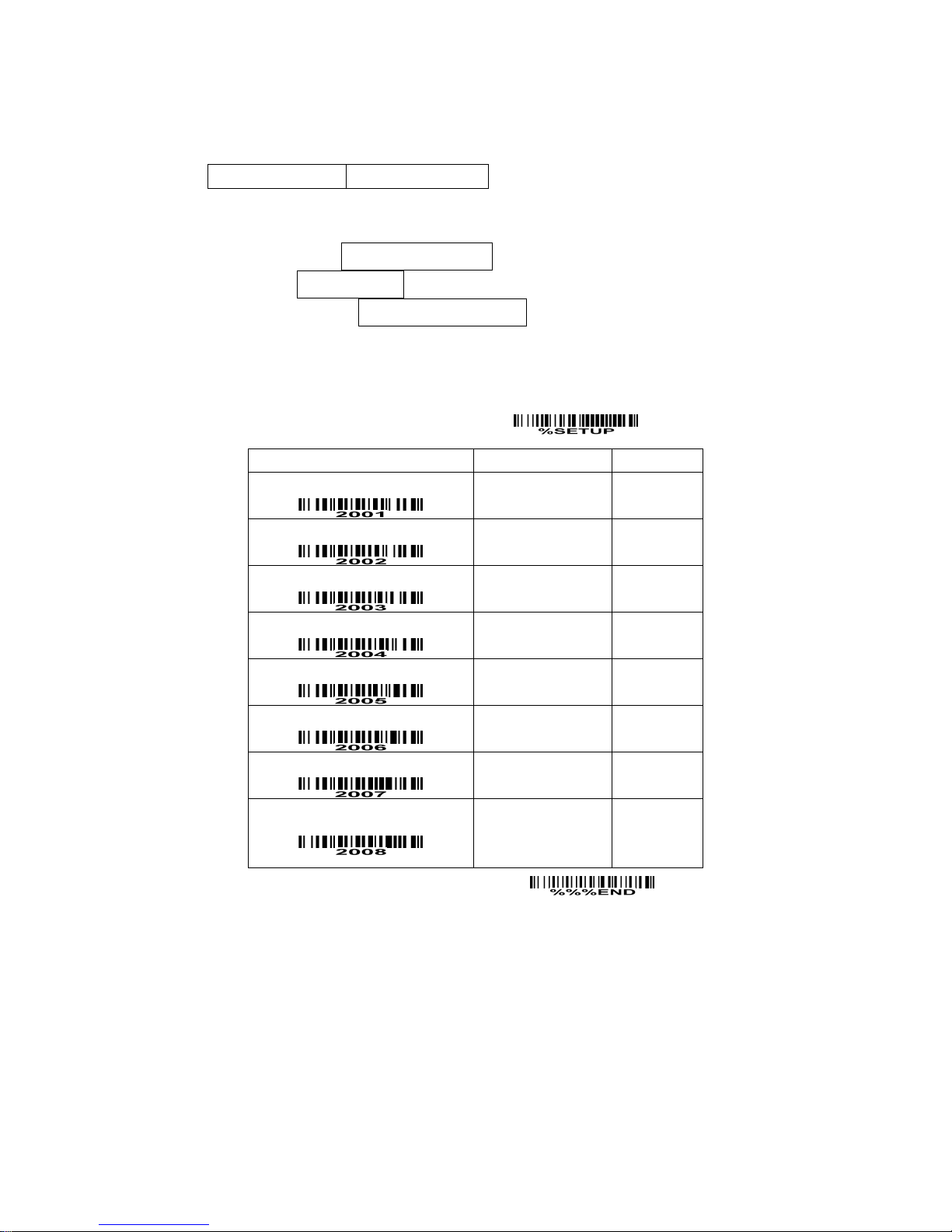
28
Code 128
Read:
Format
Data digits (variable) Check digit (optional)
Check digit verification: The check digit is made as the sum module 103 of all data digits.
Check digit transmission: By setting Enable, check digit will be transmitted.
Max./Min. code length: Refer to Max./Min. code length of Code 39.
Code ID setting: Refer to Code ID setting of UPC-A.
Insertion group selection: Refer to Insertion group selection of UPC-A.
Truncate leading zeros: The leading “0” digits of Code 128 barcode characters can be truncated when
the feature is enabled.
SETUP
Option bar code Option Alpha. entry
Read
Disable
Enable
00
01*
Check digit verification
Disable
Enable
00
01*
Check digit transmission
Disable
Reserved
00*
01
Max. code length
00-99
00-99
00*
Min. code length
00-99
00-99
01*
Code ID setting
00-FF
16
(ASCII)
00-FF16
<K>*
Insert group selection
00-66
00-66
00*
Truncate leading zeros
Disable
All leading “0”s
Only the first “0”
00*
01
02
END
Page 33
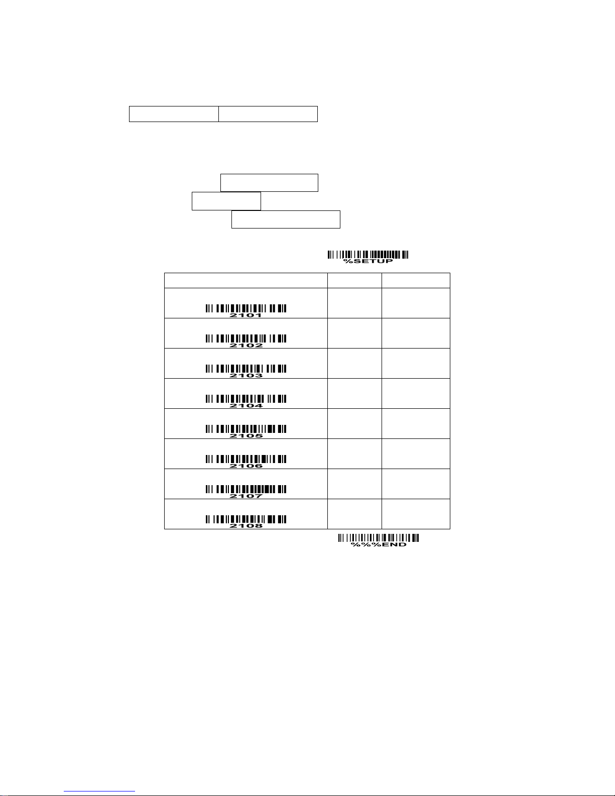
29
Code 93
Read:
Format
Data digits (variable) 2 check digits (optional)
Check digit verification: The check digit is made as the sum module 47 of the numerical values of all data
digits.
Check digit transmission: By setting Enable, check digit will be transmitted.
Max./Min. code length: Refer to Max./Min. code length of Code 39.
Code ID setting: Refer to Code ID setting of UPC-A.
Insertion group selection: Refer to Insertion group selection of UPC-A.
SETUP
Option bar code Option Alpha. entry
Read
Disable
Enable
00
01*
Check digit verification
Disable
Enable
00
01*
Check digit transmission
Disable
Enable
00*
01
Max. code length
00-99
00-99
00*
Min. code length
00-99
00-99
01*
Code ID setting
00-FF
16
(ASCII)
00-FF16
<L>*
Insert group selection
00-66
00-66
00*
Reserved
END
Page 34
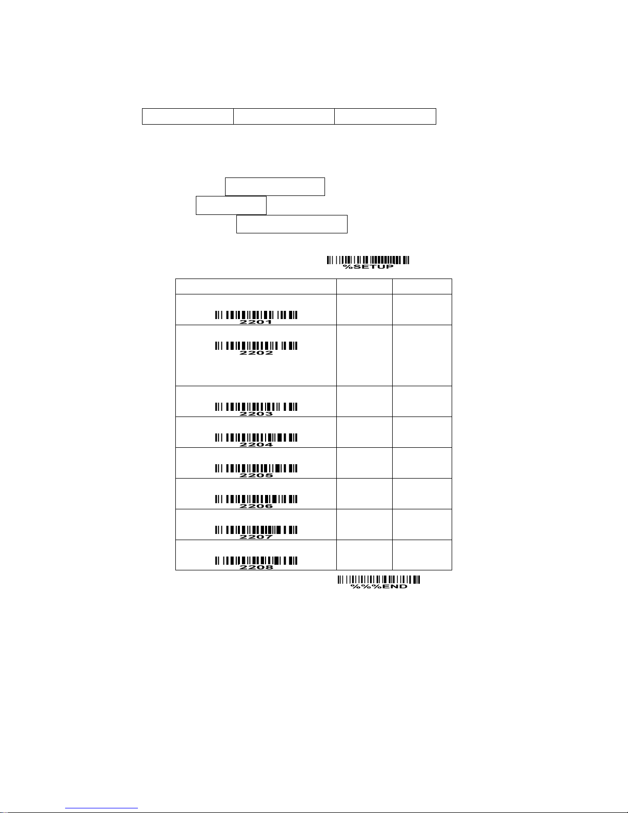
30
Code 11
Read:
Format
Data digits (variable) Check digit 1 (optional ) Check digit 2 (optional)
Check digit verification: The check digit is presented as the sum module 11 of all data digits.
Check digit transmission: By setting Enable, check digit 1 and check digit 2 will be transmitted upon your
selected check digit verification method.
Max./Min. code length: Refer to Max./Min. code length of Code 39.
Code ID setting: Refer to Code ID setting of UPC-A.
Insertion group selection: Refer to Insertion group selection of UPC-A.
SETUP
Option bar code Option Alpha. entry
Read
Disable
Enable
00
01*
Check digit verification
Disable
One digit
Reserved
Reserved
00
01*
02
03
Check digit transmission
Disable
Enable
00*
01
Max. code length
00-99
00-99
00*
Min. code length
00-99
00-99
00*
Code ID setting
00-FF16
(ASCII)
00-FF16
<V>*
Insert group selection
00-66
00-66
00*
Reserved
END
Page 35
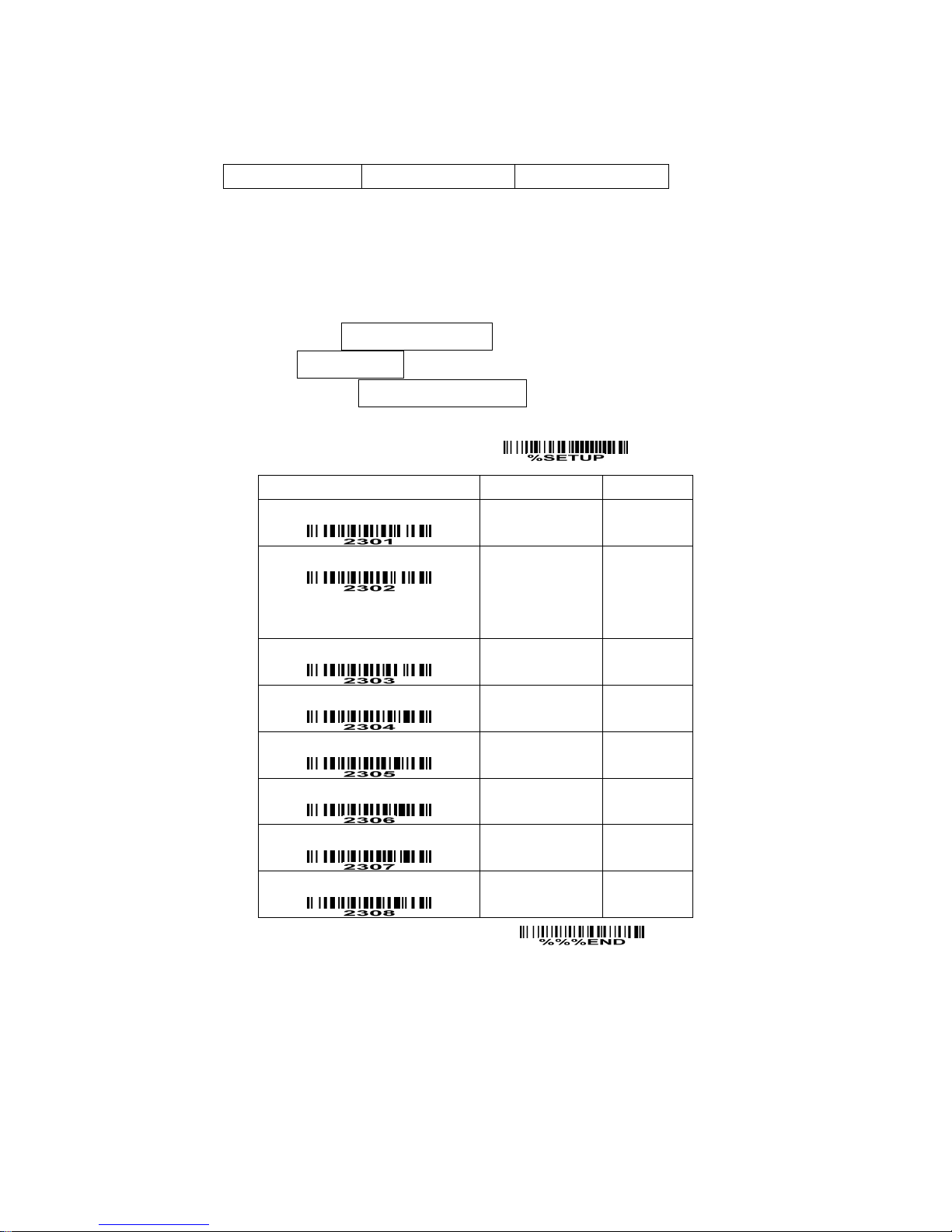
31
MSI/Plessey
Read:
Format
Data digits (variable) Check digit 1 (optional) Check digit 2 (optional)
Check digit verification: The MSI/Plessey has one or two optional check digits. There are three
methods of verifying check digits, i.e. Mod10, Mod10/10 and Mod 11/10. The check digit 1 and check
digit 2 will be calculated as the sum module 10 or 11 of the data digits.
Check digit transmission: By setting Enable, check digit 1 and check digit 2 will be transmitted upon your
selected check digit verification method.
Max./Min. code length: Refer to Max./Min. code length of Code 39.
Code ID setting: Refer to Code ID setting of UPC-A.
Insertion group selection: Refer to Insertion group selection of UPC-A.
SETUP
Option bar code Option Alpha. entry
Read
Disable
Enable
00*
01
Check digit verification
Disable
1 digit (mod 10)
Reserved
Reserved
00*
01
02
03
Check digit transmission
Disable
Enable
00*
01
Max. code length
00-99
00-99
00*
Min. code length
00-99
00-99
00*
Code ID setting
00-FF
16
(ASCII)
00-FF16
<O>*
Insert group selection
00-66
00-66
00*
Reserved
END
Page 36
32
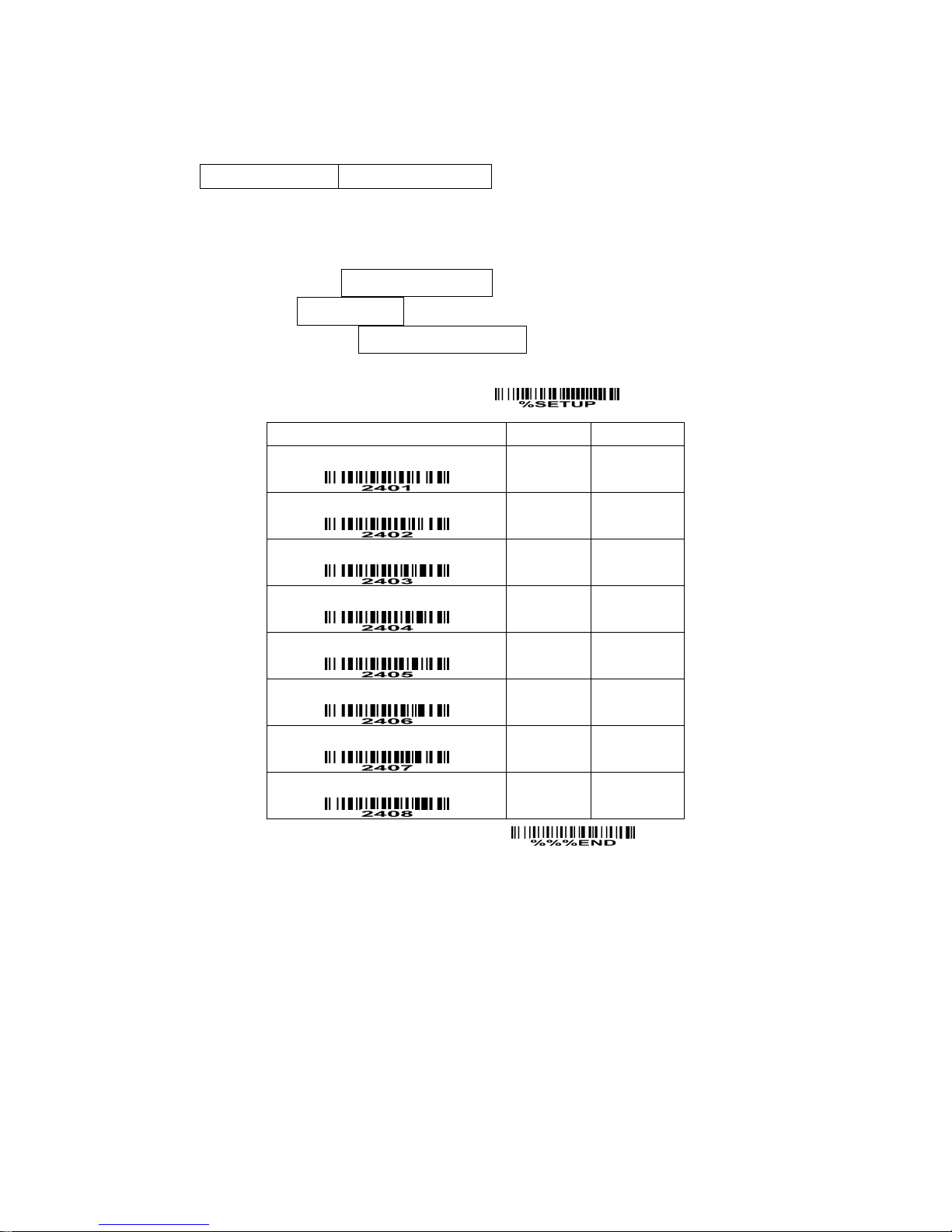
UK/Plessey
Read:
Format
Data digits (variable) 2 check digits (optional)
Check digit verification: The UK/Plessey has one or two optional check digits. The check digit 1 and
check digit 2 will be calculated as the sum module 10 or 11 of the data digits.
Check digit transmission: By setting Enable, check digit will be transmitted.
Max./Min. code length: Refer to Max./Min. code length of Code 39.
Code ID setting: Refer to Code ID setting of UPC-A.
Insertion group selection: Refer to Insertion group selection of UPC-A.
SETUP
Option bar code Option Alpha. entry
Read
Disable
Enable
00*
01
Check digit verification
Disable
Enable
00
01*
Check digit transmission
Disable
Enable
00*
01
Max. code length
00-99
00-99
00*
Min. code length
00-99
00-99
01*
Code ID setting
00-FF
16
(ASCII)
00-FF16
<U>*
Insert group selection
00-66
00-66
00*
Reserved
END
Page 37
33
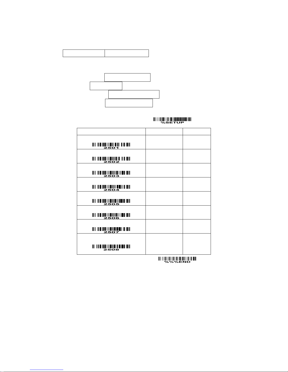
UCC/EAN 128
Read:
Format
Data digits (variable) Check digit (optional)
Check digit verification: The check digit is made as the sum module 103 of all data digits.
Check digit transmission: By setting Enable, check digit will be transmitted.
Max. /Min. code length: Refer to Max./Min. code length of Code 39.
Code ID setting: Refer to Code ID setting of UPC-A.
Insertion group selection: Refer to Insertion group selection of UPC-A.
Truncate leading zeros: Refer to Truncate leading zeros of Code 128.
SETUP
Option bar code Option Alpha. entry
Read
Disable
Enable
00
01*
Check digit verification
Disable
Enable
00
01*
Check digit transmission
Disable
Reserved
00*
01
Max. code length
00-99
00-99
00*
Min. code length
00-99
00-99
01*
Code ID setting
00-FF16
(ASCII)
00-FF16
<K>*
Insert group selection
00-66
00-66
00*
Truncate leading zeros
Disable
All leading “0”s
Only the first “0”
00*
01
02
END
Page 38
34
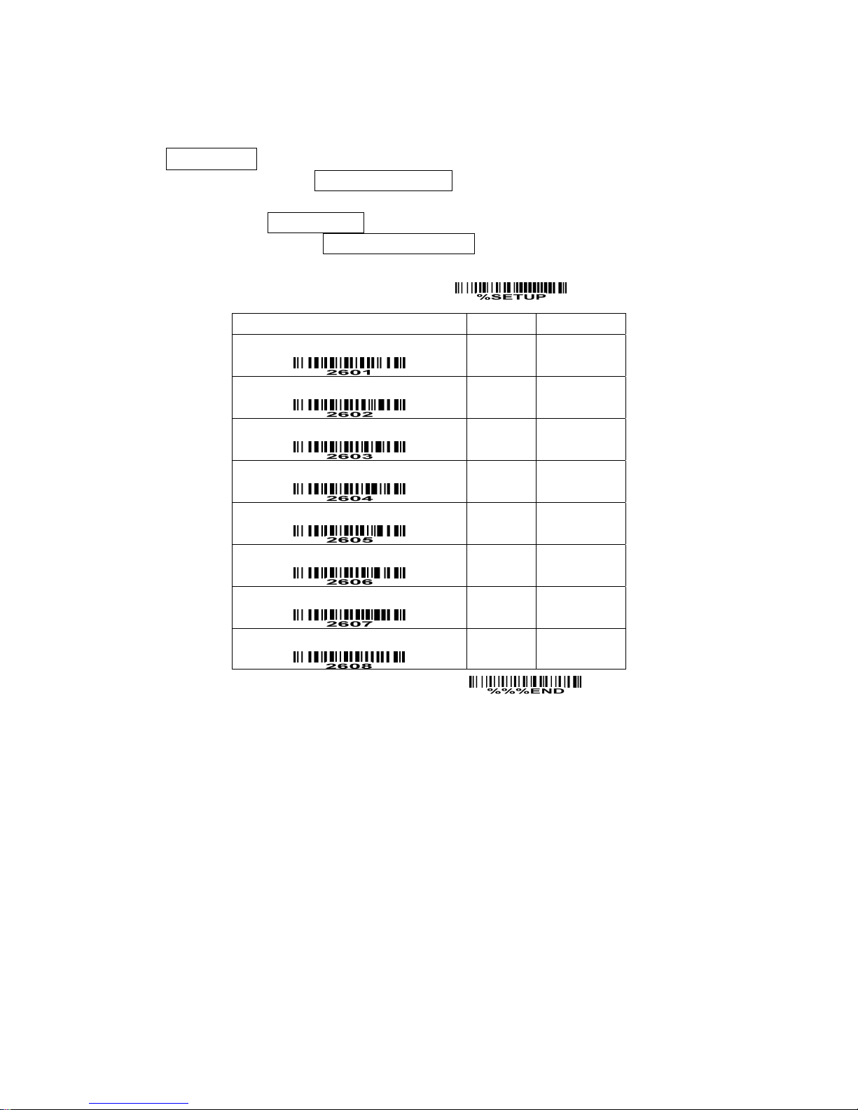
China Post
Read:
Format
11 Data digits
Max. /Min. code length: Refer to Max./Min. code length of Code 39. The code length of China Post is
11.
Code ID setting: Refer to Code ID setting of UPC-A.
Insertion group selection: Refer to Insertion group selection of UPC-A.
SETUP
Option bar code Option Alpha. entry
Read
Disable
Enable
00
01*
Reserved
Reserved
Max. code length
00-99
00-99
11*
Min. code length
00-99
00-99
11*
Code ID setting
00-FF
16
(ASCII)
00-FF16
<T>*
Insert group selection
00-66
00-66
00*
Reserved
END
Page 39
35
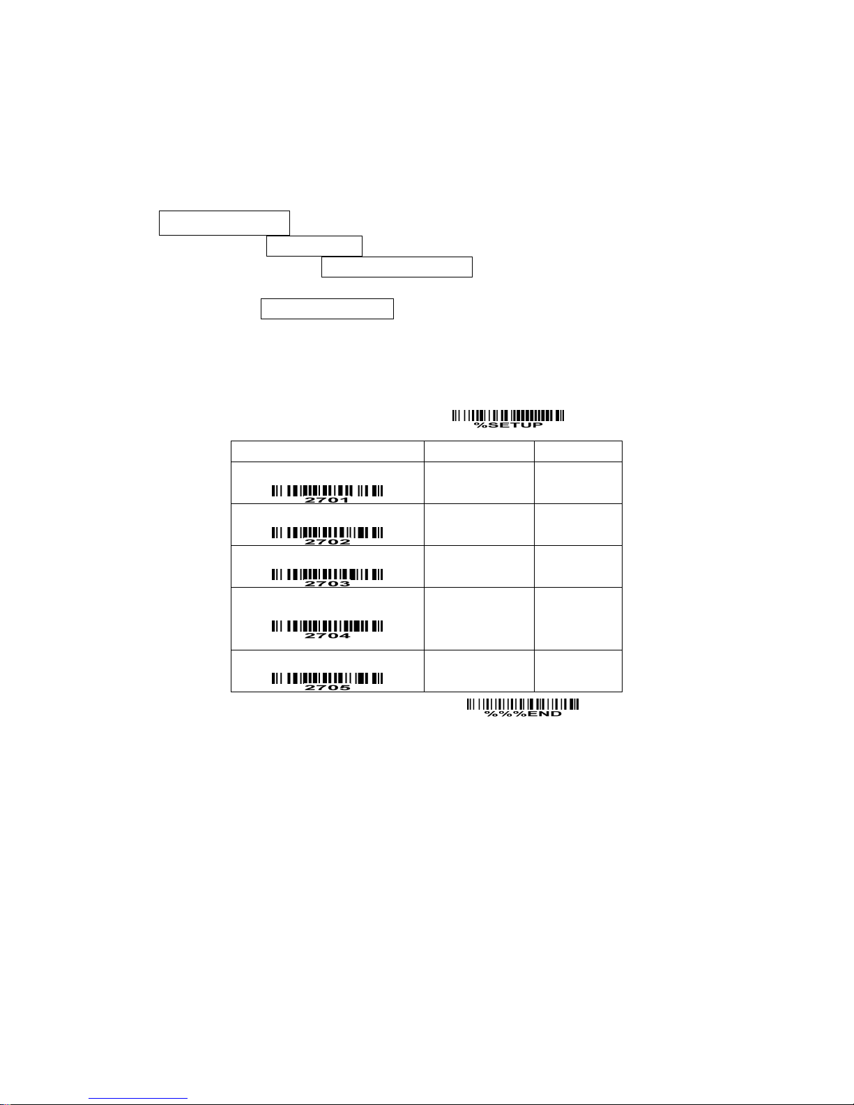
GS1 DataBar (GS1 DataBar Truncated)
GS1 DataBar Truncated is structured and encoded the same as the standard GS1 DataBar format,
except its height is reduced to a 13 modules minimum; while GS1 DataBar should have a height greater
than or equal to 33 modules.
Read:
Format
16 Data digits
Code ID setting: Refer to Code ID setting of UPC-A.
Insertion group selection: Refer to Insertion group selection of UPC-A.
Conversion:
UCC/EAN 128- Refer to Code ID transmission of String transmission, ]Cm will be identified as AIM ID.
UPC-A or EAN-13- Barcode beginning with a single zero as the first digit has the leading “010” stripped
and the barcode reported as EAN-13. Barcode beginning with two or more zeros but not six zeros has
the leading “0100” stripped and the barcode reported as UPC-A.
SETUP
Option bar code Option Alpha. entry
Read
Disable
Enable
00
01*
Code ID setting
00-FF16
(ASCII)
00-FF16
<R >*
Insert group selection
00-66
00-66
00*
Conversion
None
UCC/EAN 128
UPC-A or EAN-13
00*
01
02
Reserved
END
Page 40
36
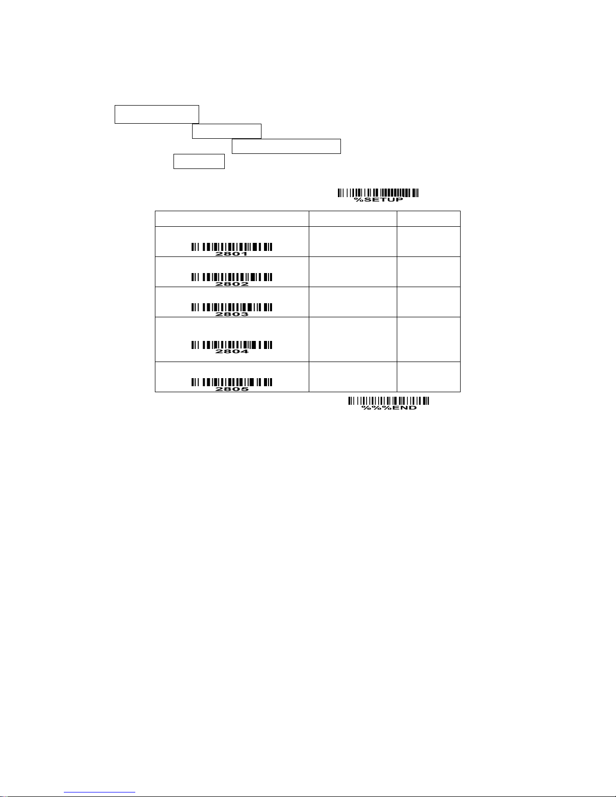
GS1 DataBar Limited
Read:
Format
16 Data digits
Code ID setting: Refer to Code ID setting of UPC-A.
Insertion group selection: Refer to Insertion group selection of UPC-A.
Conversion: Refer to Conversion of GS1 DataBar (GS1 DataBar Truncated).
SETUP
Option bar code Option Alpha. entry
Read
Disable
Enable
00
01*
Code ID setting
00-FF
16
(ASCII)
00-FF16
<R >*
Insert group selection
00-66
00-66
00*
Conversion
None
UCC/EAN 128
UPC-A or EAN-13
00*
01
02
Reserved
END
Page 41
37
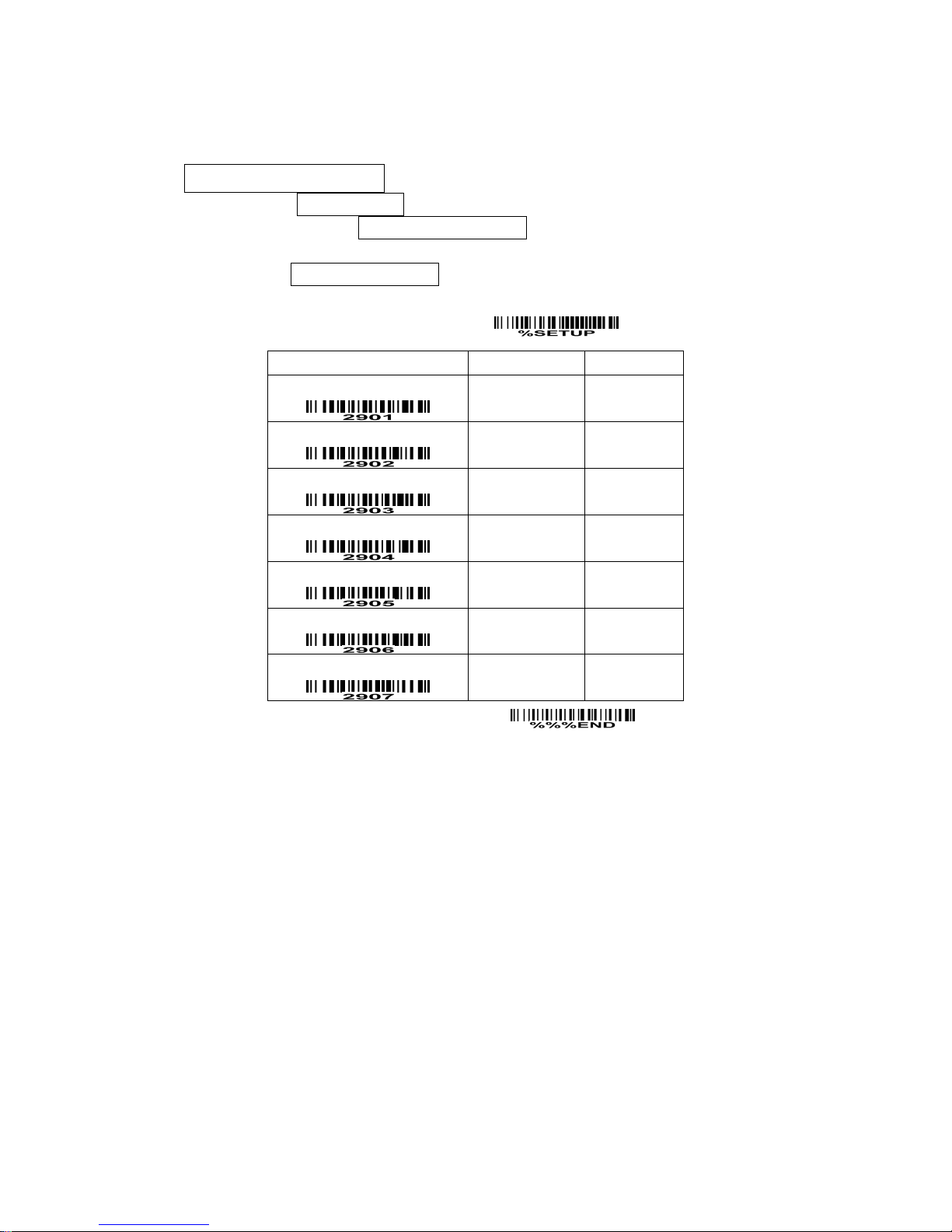
GS1 DataBar Expanded
Read:
Format
Data characters (variable)
Code ID setting: Refer to Code ID setting of UPC-A.
Insertion group selection: Refer to Insertion group selection of UPC-A.
Conversion:
UCC/EAN 128- Refer to Code ID transmission of String transmission, ]Cm will be identified as AIM ID.
SETUP
Option bar code Option Alpha. entry
Read
Disable
Enable
00
01*
Max. code length
00-99
00-99
00*
Min. code length
00-99
00-99
01*
Code ID setting
00-FF16
(ASCII)
00-FF16
<R >*
Insert group selection
00-66
00-66
00*
Conversion
None
UCC/EAN 128
00*
01
Reserved
END
Page 42
38
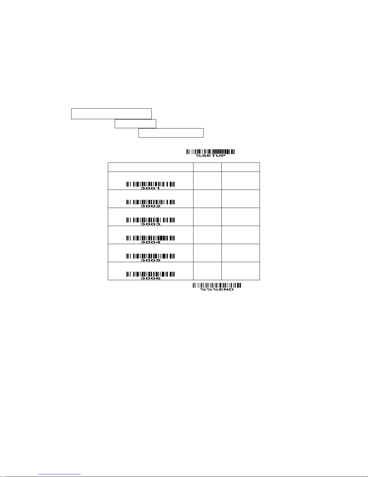
PDF417
This decoder is only applied with a specified firmware.
The symbol size in the standard of PDF417 says, number of rows: 3 to 90, and number of columns: 1 to
30. This scanner can only decode PDF417 at rows from 3 to 40 and columns from 1 to 20.
The error correction level for a PDF417 symbol is from 0 to 8. This scanner can only support the levels
from 0 to 6.
Read:
Format
Data characters (variable)
Code ID setting: Refer to Code ID setting of UPC-A.
Insertion group selection: Refer to Insertion group selection of UPC-A.
SETUP
Option bar code Option Alpha. entry
Read
Disable
Enable
00*
01
Max. code length
00-99
00-99
00*
Min. code length
00-99
00-99
01*
Code ID setting
00-FF
16
(ASCII)
00-FF16
<P>*
Insert group selection
00-66
00-66
00*
Reserved
END
Page 43
39
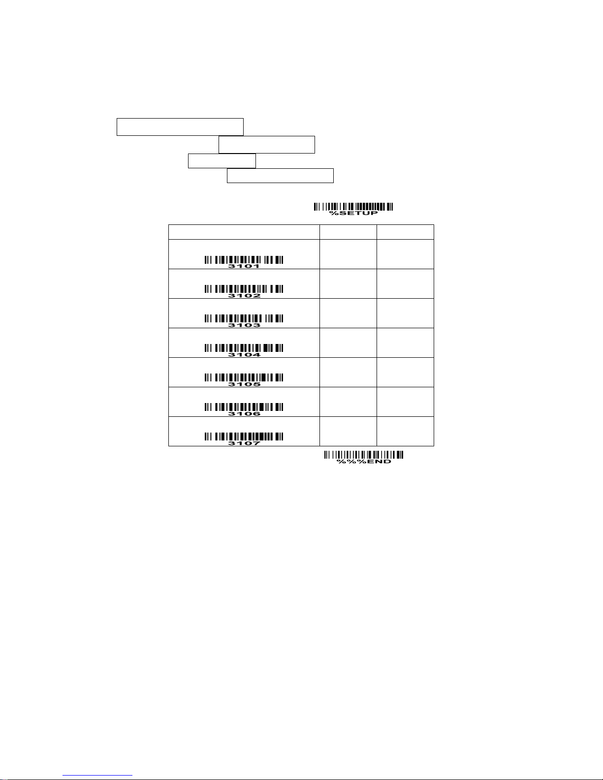
MicroPDF417
This decoder is only applied with a specified firmware.
Read:
Format
Data characters (variable)
Max. /Min. code length: Refer to Max./Min. code length of Code 39.
Code ID setting: Refer to Code ID setting of UPC-A.
Insertion group selection: Refer to Insertion group selection of UPC-A.
SETUP
Option bar code Option Alpha. entry
Read
Disable
Enable
00*
01
Max. code length
00-99
00-99
00*
Min. code length
00-99
00-99
01*
Code ID setting
00-FF16
(ASCII)
00-FF16
<P>*
Insert group selection
00-66
00-66
00*
Reserved
Reserved
END
Page 44

40
China Finance
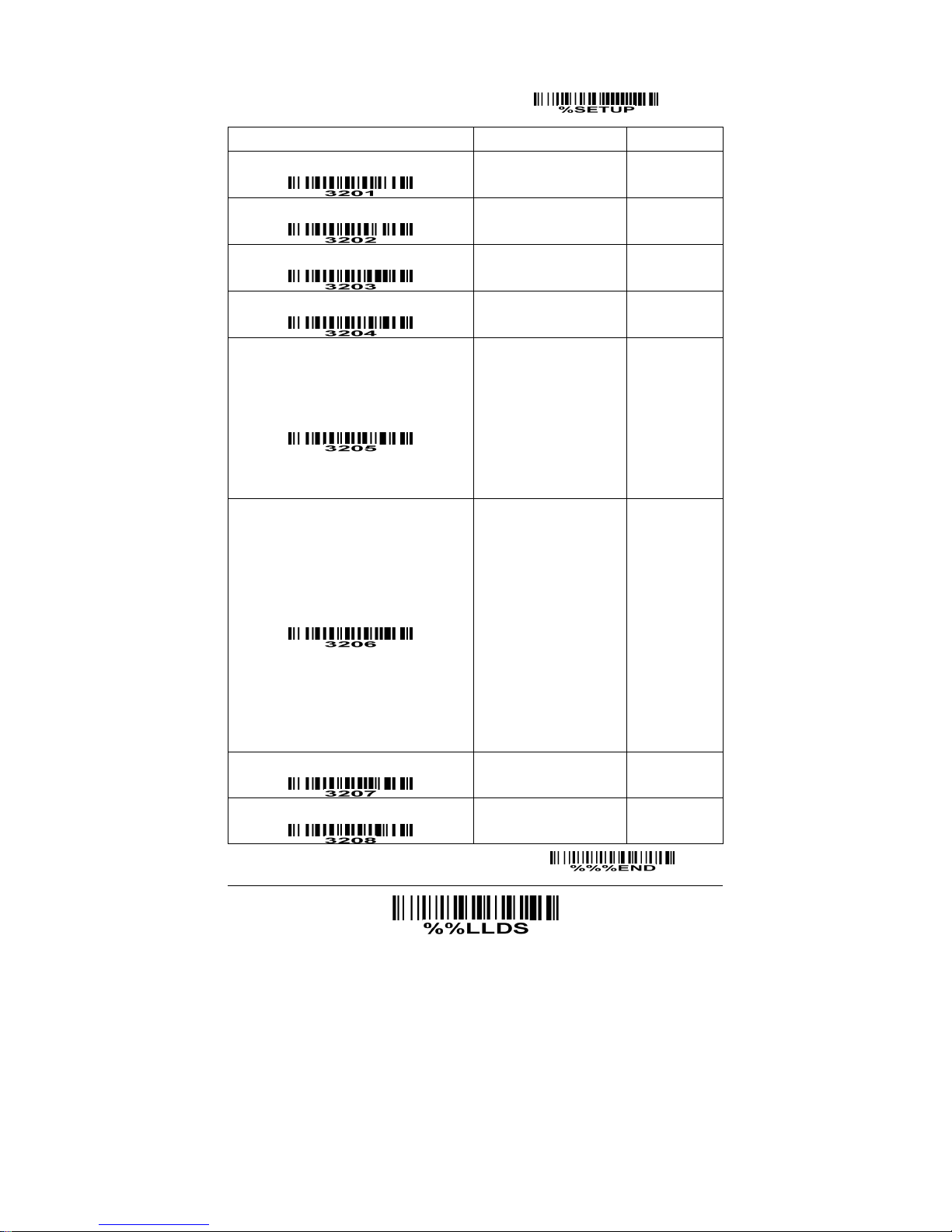
Note: This type of barcode is not Omni-directionally decodable. The encodable character set includes
numeric 0 to 9. Among the symbol of 0 to 9, 0 and 2, 4 and 9, 5 and 8, 6 and 7, have the symmetrical
pattern; the pattern of 1 and 3 is symmetrical.
Read:
Format
10 Data digits
Max./Min. code length: Refer to Max./Min. code length of Code 39.
Check digit verification: The check digit is made as the sum module 10 of the numerical values of all data
digits.
Leading character 5/6/7/8/9 converted to A/B/C/D/E: By setting, leading character 5/6/7/8/9 can be
converted to A/B/C/D/E.
Leading character assignment: By setting, only the barcode with the assigned leading character can be
output.
Code ID setting: Refer to Code ID setting of UPC-A.
Insertion group selection: Refer to Insertion group selection of UPC-A.
Page 45
41
SETUP
Option bar code Option Alpha. entry
Read
Disable
Enable
00
01*
Max. code length
00-99
00-99
10*
Min. code length
00-99
00-99
10*
Check digit verification
Disable
Reserved
00*
01
Leading character 5/6/7/8/9
converted to A/B/C/D/E
Disable
Enable
Only 5 converted to A
Only 6 converted to B
Only 7 converted to C
Only 8 converted to D
Only 9 converted to E
00
01*
02
03
04
05
06
Leading character assignment
Disable
Assigned to 0
Assigned to 5(A)
Assigned to 6(B)
Assigned to 7(C)
Assigned to 8(D)
Assigned to 9(E)
Assigned to 1
Assigned to 2
Assigned to 3
Assigned to 4
00
01*
02
03
04
05
06
07
08
09
10
Code ID setting
00-FF
16
(ASCII)
00-FF16
<Y>*
Insert group selection 00-66
00-66
00*
END
Laser Light Direction Setting: By scanning the barcode above, the
decoding direction of the scanner’s laser light is from left to righ
t. By scanning the up-side-down barcode above, the decoding di
rection of the scanner’s laser light is from right to left.
Page 46
42
G1-G6 & FN1 substitution string setting
Format of barcode data transmission
Prefix Code name Preamble Code ID Code length Code data Code ID Postamble Suffix
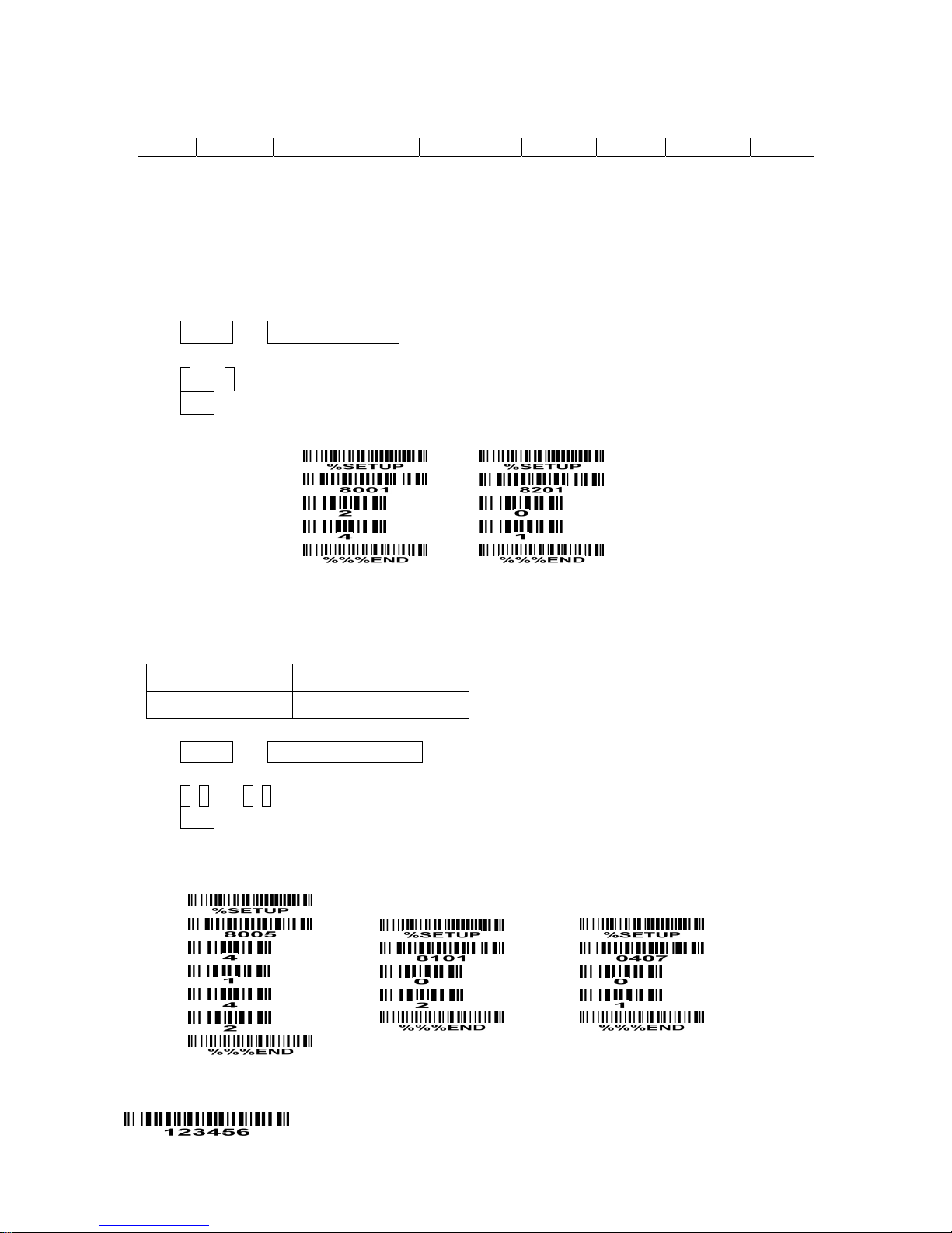
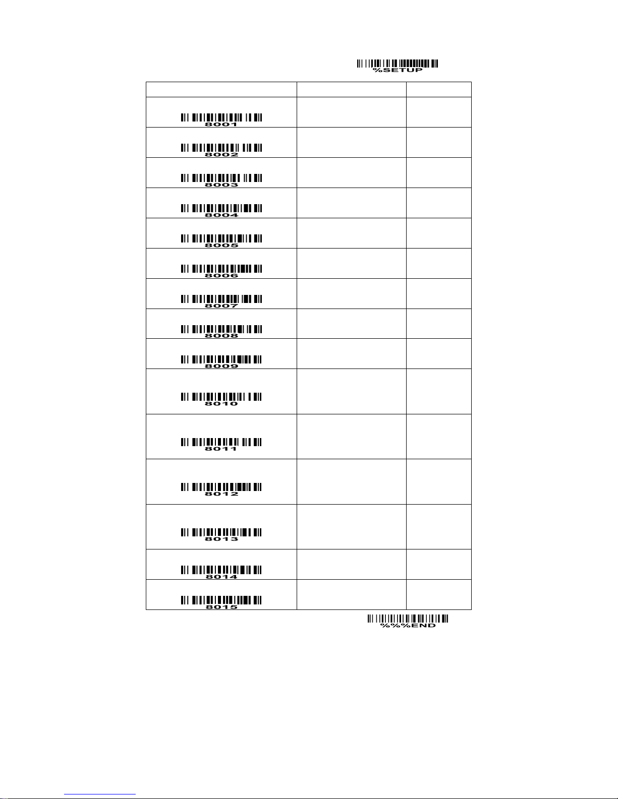
Suffix string setting: The <enter > key is represented in different ASCII when it is applied by different OS.
For a Windows/DOS OS, <enter> is represented as <CR><LF> (0x0D 0x0A); for an APPLE MAC OS,
<enter> is represented as <CR> (0x0D); for a Linux/Unix OS, <enter> is represented as <LF> (0x0A).
Prefix/Suffix string setting: & Preamble/Postamble string setting:
They are appended to the data automatically when a barcode is decoded.
Example: Add a symbol of “$” as a prefix for all symbologies.
Steps:
1) Scan SETUP and Prefix string setting barcode.
2) Use the ASCII table to find the value of $→24.
3) Scan 2 and 4 from the barcode on the foldout back page.
4) Scan END barcode.
Scanning steps: Scan the following barcodes in order.
Insert G1/G2/G3/G4 string setting: The scanner offers 4 positions and 4 character strings to insert
among the symbol.
Example: Set G1 string to be “AB”.
Original code data “1 2 3 4 5 6”
Output code data “1 2 A B 3 4 5 6”
Steps:
1) Scan SETUP and Insert G1 string setting barcode.
2) Use the ASCII table to find the value of A→41, B→42.
3) Scan 4, 1 and 4, 2 from the barcode on the foldout back page.
4) Scan END barcode.
5) Refer to the chapter of G1-G4 string position & Code ID position.
6) Refer to the chapter of Hand-held scan & some global settings.
Testing barcode:
Page 47
43
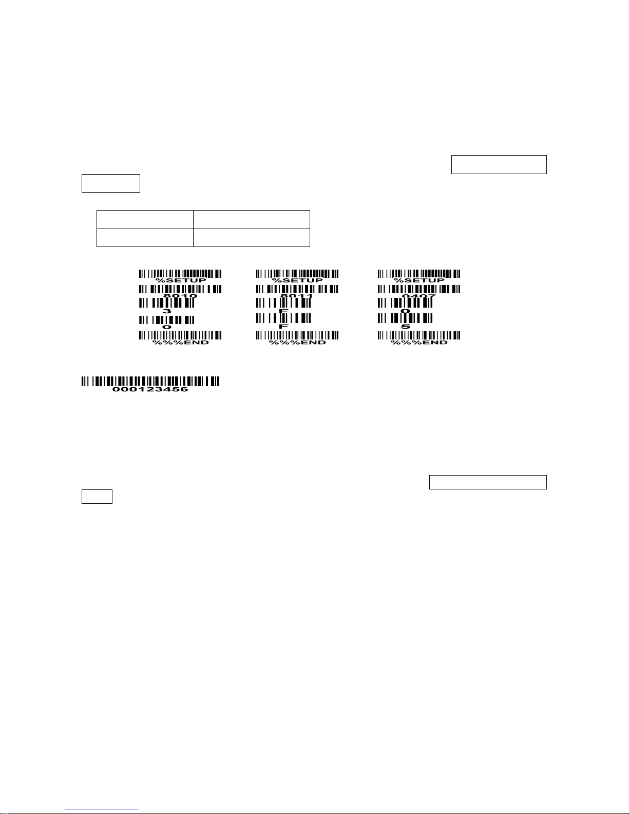
FN1 substitution string setting: The FN1 character (0x1D) in an UCC/EAN128 barcode, or a Code 128
barcode, or a GS1 DataBar barcode can be substituted with a defined string.
Truncate leading G5 string setting: By setting, a defined leading character or string can be truncated.
Also a single character can be un-defined.
Repeat of a G5 character setting: While G5 is set as a single defined/un-defined character, G5 can also
be set to be repeated. This setting is ignored when the truncate number is more than the barcode data
characters. The option of “FF” for this setting is not active while the option of Truncate leading G5
string setting is “00”.
Example: Truncate all leading zeros for all symbologies.
Original code data “0001 2 3 4 5 6”
Output code data “1 2 3 4 5 6”
Steps:
Testing barcode:
Truncate ending G6 string setting: By setting, a defined ending character or string can be truncated.
Also a single character can be un-defined.
Repeat of a G6 character setting: While G5 is set as a single defined/un-defined character, G6 can also
be set to be repeated. This setting is ignored when the truncate number is more than the barcode data
characters. The option of “FF” for this setting is not active while the option of Truncate ending G6 string
setting is “00”.
Page 48
44
SETUP
Option bar code Option Alpha. entry
Prefix string setting
0-22 characters
None
00-FF16
00*
Suffix string setting
0-22 characters
<ENTER>
00-FF16
0A0D*
Preamble string setting
0-22 characters
None
00-FF
16
00*
Postamble string setting
0-22 characters
None
00-FF16
00*
Insert G1 string setting
0-22 characters
None
00-FF16
00*
Insert G2 string setting
0-22 characters
None
00-FF16
00*
Insert G3 string setting
0-22 characters
None
00-FF16
00*
Insert G4 string setting
0-22 characters
None
00-FF16
00*
FN1 substitution string setting
0-4 characters
<SP>
00-FF16
20*
Truncate leading G5 string setting
A un-defined character
1-22 defined characters
<0>
00
01-7F16
30*
Repeat of a G5 character setting
Once
Defined times
Un-defined times (All)
01*
01-22
FF
Truncate ending G6 string setting
A un-defined character
1-22 defined characters
<0>
00
01-7F16
30*
Repeat of a G6 character setting
Once
Defined times
Un-defined times (All)
01*
01-22
FF
Single character C1 replacement
<0000>
0000*
0000-FFFF
16
Single character C2 replacement
END
Page 49
45
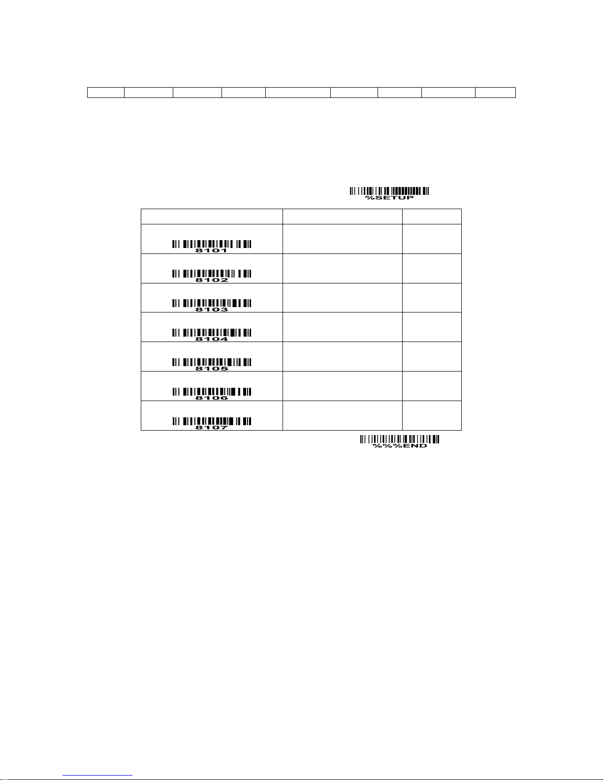
G1-G4 string position & Code ID position
Format of barcode data transmission
Prefix Code name Preamble Code ID Code length Code data Code ID Postamble Suffix
Insert G1/G2/G3/G4 string position: The scanner offers 4 positions to insert strings among the symbol.
In case of the insertion position is greater than the length of the symbol, the insertion of string is not
effective.
Code ID position: It is allowed to select different positions of code ID placement.
SETUP
Option bar code Option Alpha. entry
Insert G1 string position
00-99
00-99
00*
Insert G2 string position
00-99
00-99
00*
Insert G3 string position
00-99
00-99
00*
Insert G4 string position
00-99
00-99
00*
Code ID position
Before code data
After code data
00*
01
Reserved
Reserved
END
Page 50

46
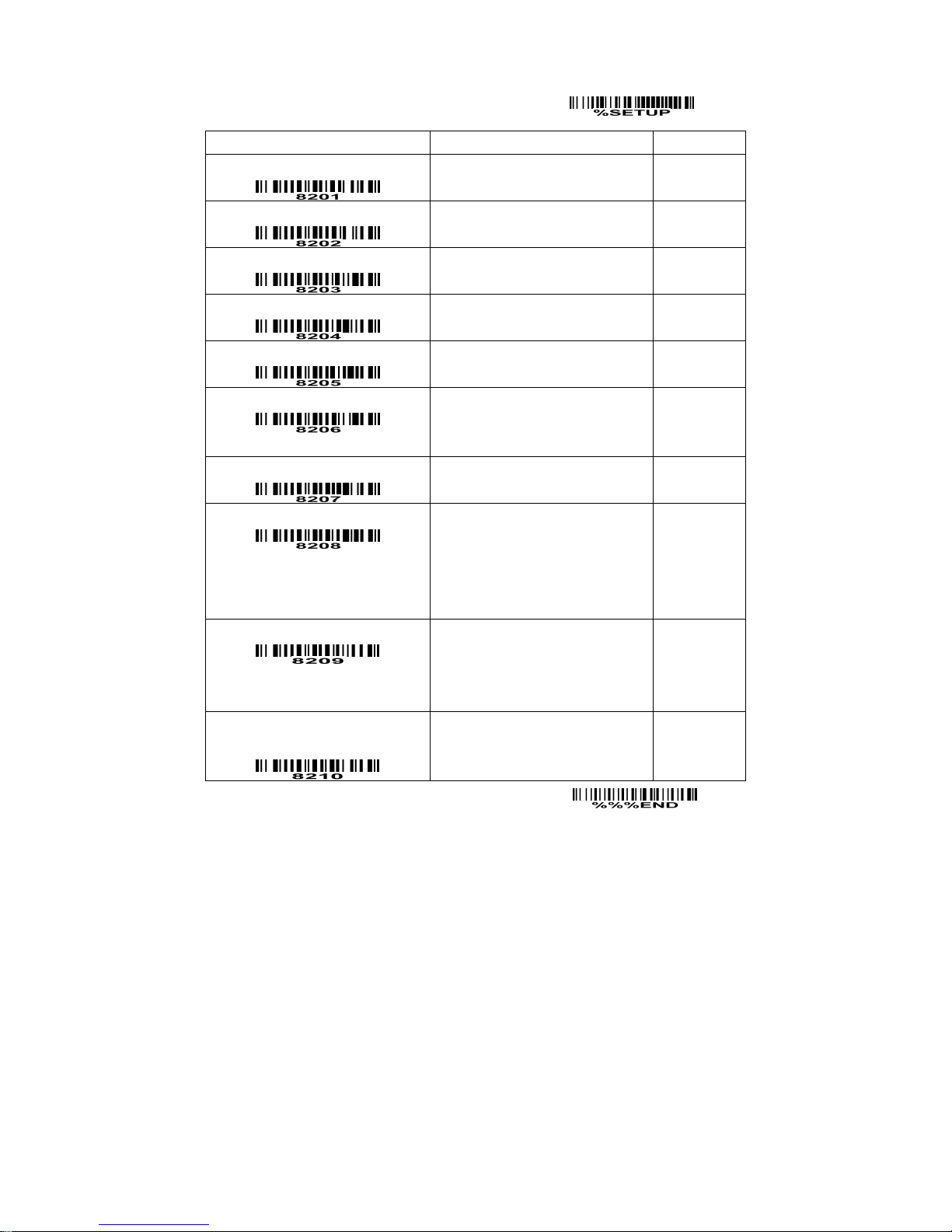
String transmission
Note: The information in this chapter is closely related to the chapter of String setting.
Format of barcode data transmission
Prefix Code name Preamble Code ID Code length Code data Code ID Postamble Suffix
Preamble transmission: By setting Enable, preamble will be appended before the data transmitted.
Postamble transmission: By setting Enable, postamble will be appended after the data is transmitted.
Code ID transmission: Code ID can be transmitted in the format of either Proprietary ID or AIM ID.
Refer to the chapter of Default setting for each barcode.
Code length transmission: The length of code data string can be transmitted before the code data when
Enable is selected. The length is represented by a number with two digits.
Code name transmission: By setting Enable, code name will be transmitted before code data.
Case conversion: The characters within code data or the whole output string can be set in either upper
case or lower case.
FN1 substitution transmission: The scanner supports a FN1 substitution feature for keyboard wedge,
USB and RS-232 interface. The replacement string of FN1 can be chosen by user (see chapter of
G1-G6 & FN1 substitution string setting).
All-control-character string transmission with string setting: By setting enable, all string settings, e.g.
“suffix string setting” or “Insert G1 string setting”, are active for an all-control-character string. Here a
control character means a character with ASCII between 0x00 to 0x1F.
Page 51
47
SETUP
Option bar code Option Alpha. entry
Prefix transmission
Disable
Enable
00*
01
Suffix transmission
Disable
Enable
00
01*
Code name transmission
Disable
Enable
00*
01
Preamble transmission
Disable
Enable
00*
01
Postamble transmission
Disable
Enable
00*
01
Code ID transmission
Disable
Proprietary ID
AIM ID
00*
01
02
Code length transmission
Disable
Enable
00*
01
Case conversion
Disable
Upper (data only)
Lower (data only)
Upper (whole string)
Lower (whole string)
00*
01
02
03
04
FN1 substitution transmission
Disable
Keyboard wedge/USB
RS-232
Keyboard wedge/USB/RS-232
00*
01
02
03
All-control-character string
transmission with string setting
Disable
Enable
00*
01
END
Page 52
48
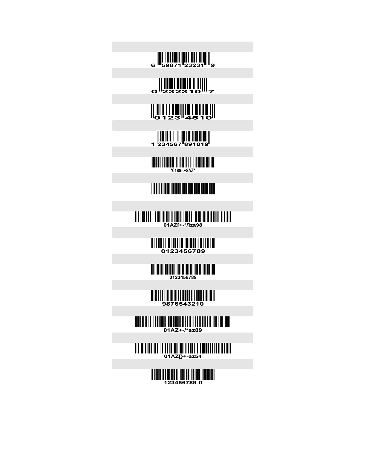
Test Chart
UPC-A
UPC-E
EAN-8
EAN-13
Code 39
Code 32
A908765439
Code 128
Interleaved 2 of 5
Industrial 2 of 5
Matrix 2 of 5
Code 93
UCC/EAN 128
Code 11
Page 53
49
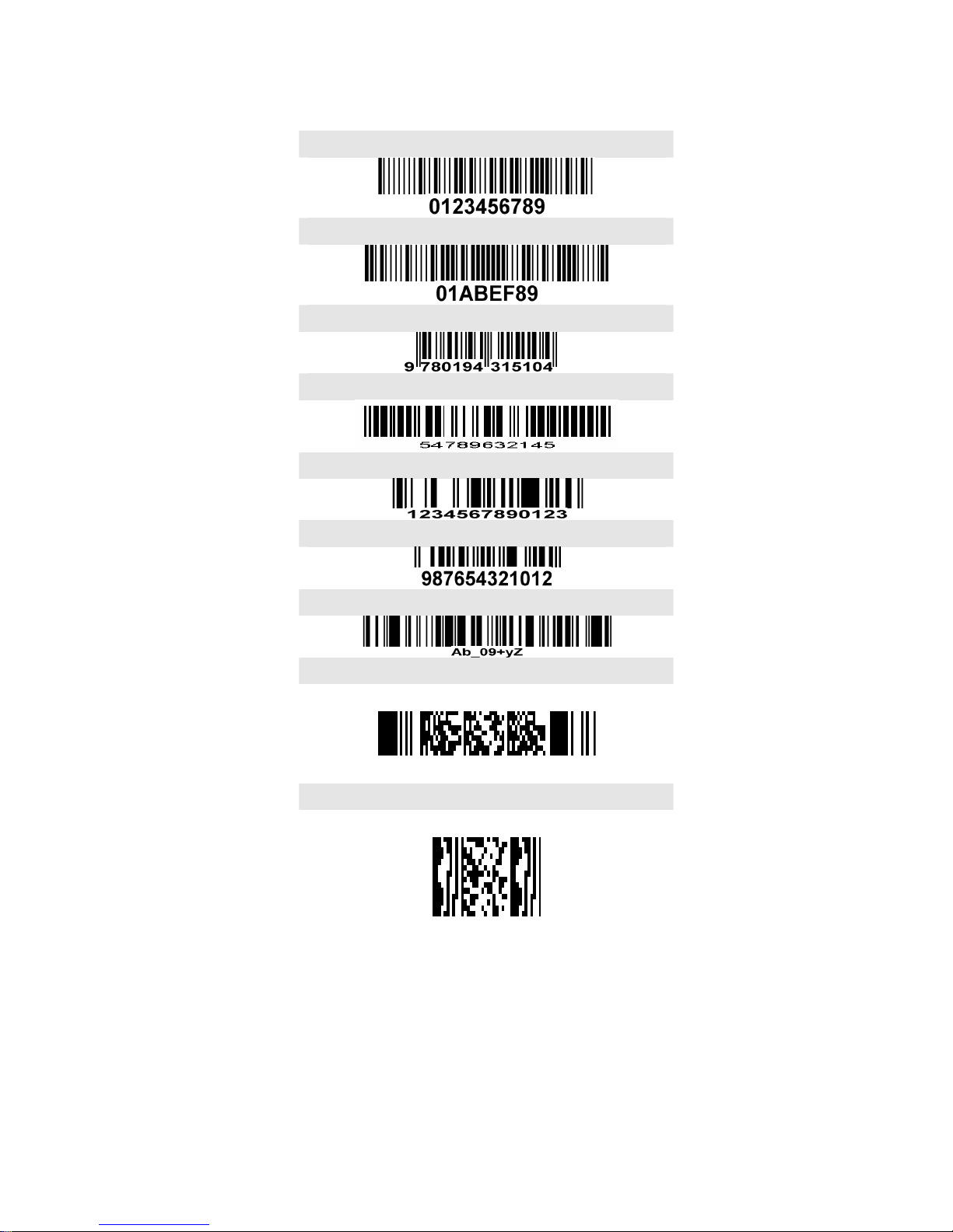
Test Chart (Continued)
MSI/Plessey
UK/Plessey
ISBN/ISSN
China Post
GS1 DataBar (GS1 DataBar Truncated)
GS1 DataBar Limited
GS1 DataBar Expanded
PDF417
01Az+-=
MicroPDF417
23+-mdo
Page 54

50
Troubleshooting
Problem Possible causes Possible solutions
No power to the
scanner.
Check the system power. Ensure the power
supply is connected.
Incorrect cables. Use the original cables.
Nothing happens when you
follow the operating
instructions, or the scanner
displays erratic behavior.
Connections are loose. Check for loose cable connections.
Bar code symbol is
unreadable.
Check the symbol to make sure it is not
defaced. Try scanning test symbols of the
same bar code type.
Scanner is not
programmed for the
correct bar code type.
Be sure the scanner is programmed to read
the type of bar code you are scanning.
Laser comes on, but the
scanner does not decode.
Distance between
scanner and bar code
is incorrect.
Move the scanner closer to or further from the
bar code.
Scanned data is incorrectly
displayed on the host.
Scanner is not
programmed to work
with the host. Check
scanner host type
parameters or editing
options.
Be sure proper host is selected.
For RS-232, ensure the scanner’s
communication parameters match the host’s
settings.
For a USB-HID keyboard or a keyboard
wedge configuration, ensure the system is
programmed for the correct keyboard type and
language, and the CAPS LOCK key is in the
correct state.
Other circumstances. Contact your distributor or the manufactory
support centre.
Page 55

51
Maintenance
Cleaning the exit window is the only maintenance required. A dirty window may affect scanning
accuracy.
1. Do not allow any abrasive material to touch the window.
2. Remove any dirt particles with a damp cloth.
3. Wipe the window using a tissue moistened with water.
4. Do not spray water or other cleaning liquids directly into the window.
5. Use a soft, dry cloth when cleaning the scanner.
Page 56
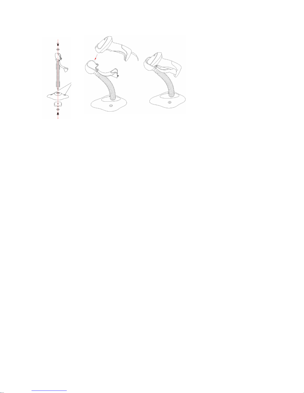
52
Assembling the stand
1. See the figure above, tighten the screws.
2. Bend the neck to the desired position for scanning.
3. Screw mounting: Screw one #10 wood screw into each screw-mount-hole until the base of the stand
is secured.
4. Tape mounting: ①Peel the paper liner off one side of each piece of tape and place the sticky
surface over each of the three rectangular tape holders. ②Peel the paper liner off the exposed
sides of each piece of tape and press the stand on a flat surface until it is secure.
Page 57

53
ASCII Table
for keyboard wedge for RS-232
H
L
0 1 0 1
0 Null NUL DLE
1 Up F1 SOH DC1
2 Down F2 STX DC2
3 Left F3 ETX DC3
4 Right F4 EOT DC4
5 PgUp F5 ENQ NAK
6 PgDn F6 ACK SYN
7 F7 BEL ETB
8 Bs F8 BS CAN
9 Tab F9 HT EM
A F10 LF SUB
B Home Esc VT ESC
C End F11 FF FS
D Enter F12 CR GS
E Insert Ctrl+ SO RS
F Delete Alt+ SI US
Notes: The 2nd and the 3rd columns above are used for keyboard wedge only.
H
L
2 3 4 5 6 7
0 SP 0 @ P ` p
1 ! 1 A Q a q
2 “ 2 B R b r
3 # 3 C S c s
4 $ 4 D T d t
5 % 5 E U e u
6 & 6 F V f v
7 ‘ 7 G W g w
8 ( 8 H X h x
9 ) 9 I Y i y
A * : J Z j z
B + ; K [ k {
C , < L \ l |
D - = M ] m }
E . > N ^ n ~
F / ? O _ o DEL
Example: ASCII “A” = “41”.
Page 58
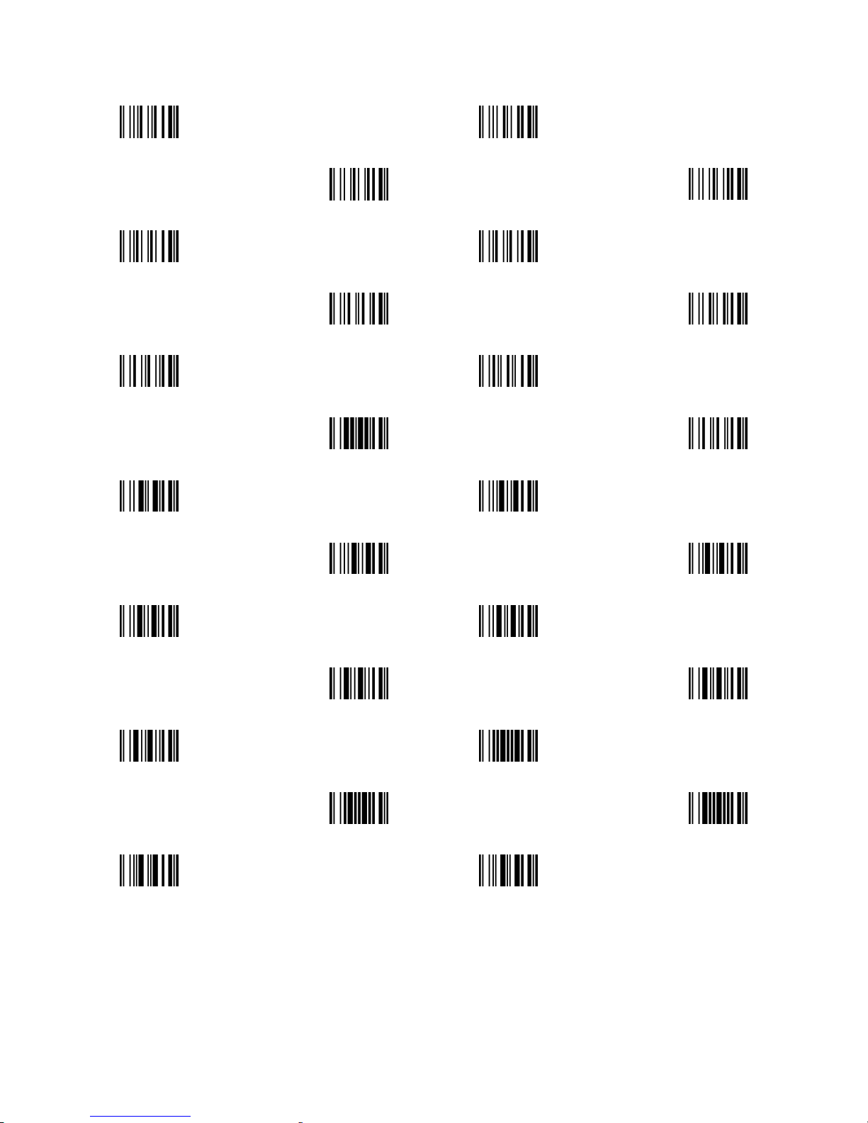
54
Barcode representing control character
Up ↑
Down ↓
Left ← Right →
Page Up
Page Down
Backspace Tab
Home
End
Enter Insert
Delete
F1
F2 F3
F4
F5
F6 F7
F8
F9
F10 Esc
F11
F12
Page 59

55
Return default parameters & others
WARNING: Default value initialization
If you wish to return the scanner to all the factory
default settings, scan the barcode above.
Firmware version list
If you wish to display the firmware version, scan
the barcode above.
Page 60

56
Configuration alphanumeric entry barcode
 Loading...