

Page 1

CODESCAN CS602 User’s Manual
2011-07-24
V1.00
Page 2

CODESCAN CS602 User’s Manual
Table of Contents
1. SAFETY PRECAUTIONS AND WARNINGS……..............3
2. INTRODUCTION...................................................................3
3. GENERAL INFORMATION-ABOUT OBDII/EOBD.........3
3.1 On-Board Diagnostics(OBD) II ..........................................4
3.2 Diagnostic Trouble Codes (DTCs)......................................4
3.3 Location of the Data Link Connector (DLC) ......................5
3.4 OBD II Readiness Monitors................................................6
3.5 OBD II Monitor Readiness Status.......................................7
3.6 OBD II Definitions..............................................................8
4. PRODUCT DESCRIPTIONS.................................................9
4.1 Outline of CS602 ................................................................9
4.2 Specifications....................................................................10
4.3 Accessories Included.........................................................10
4.4 Power supply.....................................................................10
4.5 Tool Setup.........................................................................10
4.6 Vehicle Coverage..............................................................13
5. OPERATION.........................................................................13
5.1 Connection........................................................................13
5.2 Diagnostic.........................................................................14
5.2.1 Read Codes................................................................15
5.2.2 Erase Codes...............................................................16
5.2.3 I/M Readiness............................................................17
5.2.4 Data Stream...............................................................19
5.2.5 View Freeze Frame ...................................................22
5.2.6 O2 sensor test............................................................23
5.2.7 On-board monitor test ...............................................25
5.2.8 EVAP System Test....................................................26
5.2.9 Vehicle Info...............................................................27
5.3 Code Lookup.....................................................................27
5.4 Review..............................................................................28
5.5 About CS602.....................................................................30
6 FAQ..........................................................................................30
2
Page 3

CODESCAN CS602 User’s Manual
1. Safety Precautions and Warnings
To prevent personal in jury or damage to vehicles and/or the CS602, please read
this user’s manual first carefully and observe the following safety precautions
at a minimum whenever working on a vehicle:
z Always perform automotive testing in a safe environment.
z Wear safety eye protection that meets ANSI standards.
z Keep clothing, hair, ha nds, tools, test equipment, etc. away from all moving
or hot engine parts.
z Operate the vehicle in a well-ventilated work area: Exhaust gases are
poisonous.
z Put blocks in front of the dri ve wheels and never leave the vehicle unattended
while running tests.
z Use extreme caution when working around the ignition coil, distributor cap,
ignition wires and spark plugs. These components create hazardous voltages
when the engine is running.
z Put the transmission in P (for A/T) or N (for M/T) and make sure the parking
brake is engaged.
z Keep a fire extinguisher su itable for gasoline/chemical/ electrical fires
nearby.
z Don’t connect or disconnect any test equipment while the ignition is on or the
engine is running.
z Keep the CS602 dry, c lean, free from oil/water or gre ase. Use a mild
detergent on a clean cloth to clean the outside of the CS602, when necessary.
2. Introduction
The CS602 is newly developed by CODESCAN, specially designed for car owners
or DIYs to diagnose and vehicle that is compliant to OBDII/EOBD. It not only can
reade/clear DTCs, bu t also can read live data in 2 modes , and perform mant special
tests. Tri-language make it operation easily for technician. The feature of upgrading
online ensures it can test new model cars and/or functions in the future.
NOTICE: CS602 MAY AUTOMATICALLY RESET
WHILE BEING DISTURBED BY STRONG STATIC
ELECTRICITY. THIS IS A NORMAL REACTION.
3. General Information-About OBDII/EOBD
3
Page 4

CODESCAN CS602 User’s Manual
3.1 On-Board Diagnostics (OBD) II
The first generation of On-Board Diagnostics (called OBD I) was developed by the
California Air Resources Board (ARB) and impleme nted in 1988 to monitor some of
the emission control components on vehicles. As technology evolved and the desire
to improve the On-Board Diagnostic system increased, a new generation of
On-Board Diagnostic system was developed. This second generation of On-Board
Diagnostic regulatio ns is called "OBD II".
The OBD II system is designed to monitor emission control systems and key engine
components by performing either continuous or periodic tests of specific
components and vehicle conditions. When a problem is detected, the OBD II system
turns on a warning lamp (MIL) on the vehicle instrument panel to alert the driver
typically by the phrase of “Check Engine” or “Service Engine Soon”. The system
will also store important information about the detected malfunction so that a
technician can accu rately find and fix the problem. Here bel ow follow three pieces
of such valuable information:
1) Whether the Malfunction Indicator Light (MIL) is commanded 'on' or 'off';
2) Which, if any, Diagnostic Trouble Codes (DTCs) are stored;
3) Readiness Monitor status.
3.2 Diagnostic Trouble Codes (DTCs)
OBD II Diagnostic Trouble Codes are codes that are stored by the on-board
computer diagnostic system in response to a problem found in the vehicle. These
codes identify a particular problem area and are intended to provide you with a
guide as to where a fault might be occurring within a vehicle. OBD II Diagnostic
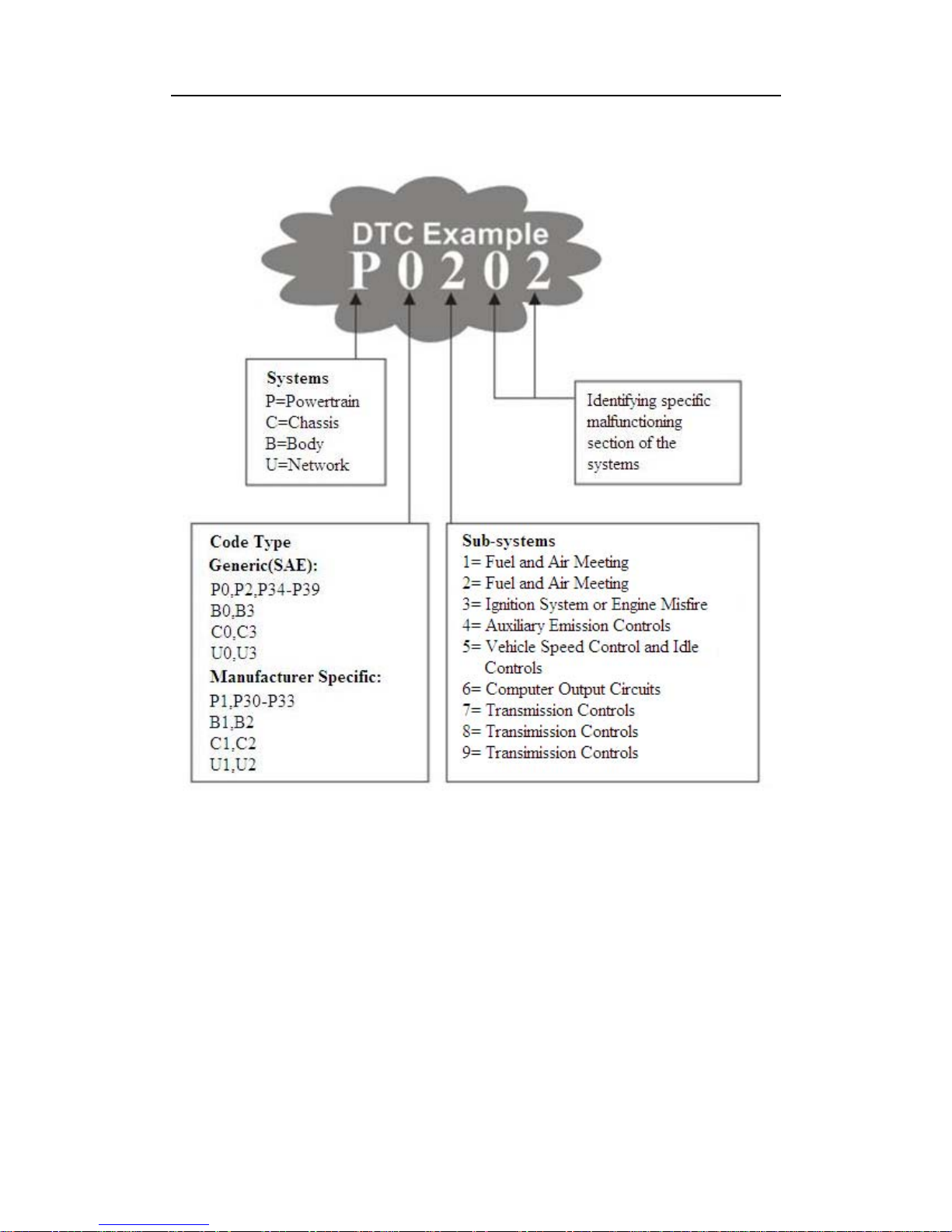
Trouble Codes consist of a f ive- digi t alph anumeric code. T he fi rst charact er, a letter,
identifies which control system sets the code. The second character, a number, 0-3;
other three charact ers, a h ex charact er, 0-9 or A-F provid e addit ional info rmation on
where the DTC originated and the operating conditions that caused it to set. Here
below is an example to illustrate the structure of the digits:
4
Page 5
CODESCAN CS602 User’s Manual
3.3 Location of the Data Link Connector (DLC)
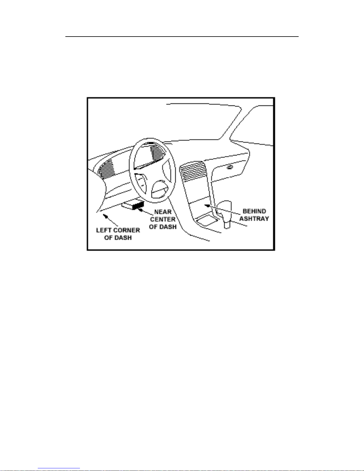
The DLC (Data Link Co nnector or Diagnostic Link Connector) is the standardi zed
16-cavity connector where diagnostic code readers interface with the vehicle's
on-board computer. The DLC is usually located 12 inches from the center of the
instrument panel (dash), under or around the driver’s side for most vehicles. If Data
Link Connector is not located under dashboard, a label should be there telling
location. For some Asian and European vehicles, the DLC is located behind the
ashtray and the ashtray must be removed to access the connector. If the DLC cannot
be found, refer to the vehicle’s service manual for the location.
5
Page 6
CODESCAN CS602 User’s Manual
3.4 OBD II Readiness Monitors
system is the Readiness Monitors, which
urrently, there are eleven OBD II Readiness Monitors (or I/M Monitors) defined by
ontinuous Monitors -- Some of the vehicle components or systems are
An important part of a vehicle’s OBD I I
are indicators used to find out if all of the emissions components have been
evaluated by the OBD II system. They are running periodic tests on specific systems
and components to ensure that they are perform ing within allowable limits.
C
the U.S. Environmental Protection Agency (EPA). Not all monitors are supported in
every vehicles and the exact number of monitors in any vehicle depends on the
motor vehicle manufac t urer’s emissions control strategy.
C
continuously tested by the vehicle’s OBD II system, while others are tested only
under specific vehicle operating conditions. The continuously monitored
components listed below are always ready:
1)Misfire
6
Page 7

CODESCAN CS602 User’s Manual
2)Fuel System
ve Components (CCM)
nce the vehicle is running, the OBD II system is cont inuously checking the above
on-Continuous Monitors -- Unlike the continuous monitors, many emissions and
System
tion
3.5 OBD II Monitor Readiness Status
vehicle’s PCM’s monitor system
he powertrain control module (PCM) sets a monitor to “Ready” or “Complete”
order for the OBD mo nitor sys tem to beco me ready, the vehicle should be driven
3)Comprehensi
O
components, monitoring key engine sensors, watching for engine misfire, and
monitoring fuel demands.
N
engine system components require the vehicle to be operated under specific
conditions before the monitor is ready. These monitors are termed non-continuous
monitors and are listed below:
1) EGR System
2) O2 Sensors
3) Catalyst
4) Evaporative
5) O2 Sensor Heater
6) Secondary air Injec
7) Heated Catalyst
8) A/C system
OBD II systems must indicate whether or not the
has completed testing on each component. Components that have been tested will be
reported as “Ready”, or “Complete”, meaning they have been tested by the OBD II
system. The purpose of recording readiness status is to allow inspectors to determine
if the vehicle’s OBD II system has tested all the components and/or systems.
T
after an appr opriate drive cycle has been perfor med. The drive cycle t hat enables a
monitor and sets readiness codes to “Ready” varies for each individual monitor.
Once a monitor is set as “Ready” or “Complete”, it will remain in this state. A
number of factors, including erasing of diagnostic trouble codes (DTCs) with a code
reader or a disconnected battery, can result in Readiness Monitors being set to “Not
Ready”. Since the three continuous monitors are constantly evaluating, they will be
reported as “Ready” all of the time. If testing of a particular supported
non-continuous monitor has not been completed, the monitor status will be reported
as “Not Complete” or “Not Ready.”
In
under a variety of normal operating conditions. These operating conditions may
include a mix of highway driving and stop and go, city type driving, and at least one
overnight-off period. For specific information on getting your vehicle’s OBD
7
Page 8

CODESCAN CS602 User’s Manual
monitor system ready, please consult your vehicle owner’s manual.
3.6 OBD II Definitions
(PCM) -- OBD II terminology for the on-board
alfunction Indicator Light (MIL) -- Malfunction Indicator Light (Service
TC -- Diagnostic Trouble Codes (DTC) that identifies which section of the
nabling Criteria -- Also termed Enabling Conditions. They are the
BD II Drive Cycle -- A specific mode of vehicle operation that provides
reeze Frame Data -- When an emissions related fault occurs, the OBD II system
Powertrain Control Module
computer that controls engine and drive train.
M
Engine Soon, Check Engine) is a term used for the light on the instrument panel. It
is to alert the d river and/or the rep air technician th at there is a prob lem with one or
more of vehicle' s systems and may cause e missions to exceed federal s tandards. If
the MIL illuminates with a steady light, it indicates that a problem has been detected
and the vehicle s houl d be s ervi ced as s oon as pos sible. Un der cer tain cond ition s, th e
dashboard light will blink or flash. This indicates a severe problem and flashing is
intended to discourage vehicle operation. The vehicle onboard diagnostic system
cannot turn the MIL off until the necessary repairs are comp leted or the condition no
longer exists.
D
emission control system has malfunctioned.
E
vehicle-specific events or conditions that must occur within the engine before the
various monitors will set, or run. Some monitors require the vehicle to follow a
prescribed “dri ve cycle” routine as part of the enabling criteria. Drive cy cles vary
among vehicles and for each monitor in any particular vehicle. Please refer to the
vehicle's factory service manual for specific e nabling procedures.
O
conditions required to set all the readiness monitors applicable to the vehicle to the
“ready” condition. The purpose of completing an OBD II drive cycle is to force the
vehicle to run its onboard diagnostics. Some form of a drive cycle needs to be
performed after DT Cs h av e b een erased from the PCM’s memory or after the batter y
has been disconnected. Running through a vehicle’s complete drive cycle will “set”
the readiness monitors so that future faults can be detected. Drive cycles vary
depending on the vehicle and the monitor that needs to be reset. For vehicle specific
drive cycle, consult the service manual.
F
not only sets a code but also records a snapshot of the vehicle operating parameters
to help in iden tifying the p roblem. This set of values i s referred to as Freeze Frame
Data and may include important engine parameters such as engine RPM, vehicle
speed, air flow, engine load, fuel pressure, fuel trim value, engine coolant
8
Page 9
CODESCAN CS602 User’s Manual
temperature, ignition timing advance, or closed loop status.
Fuel Trim (FT) - Feedback ad justments to the base fu el schedule. Short-term fuel
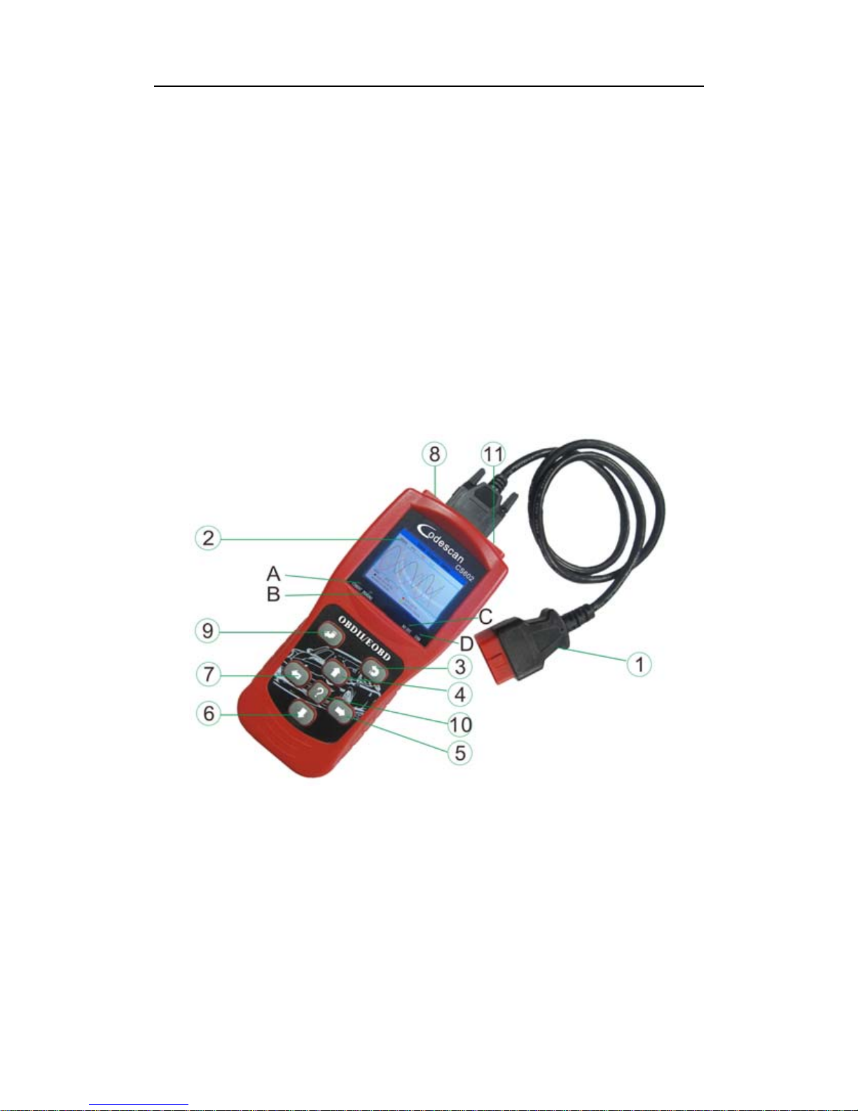
4.1 Outline of CS602
trim refers to dynamic or instantaneous adjustments. Long-term fuel trim refers to
much more gradual adjustments to the fuel calibration schedule than short-term trim
adjustments. These long-term adjustments compensate for vehicle differences and
gradual changes that occur over time.
4. Product Descriptions
Figure 3-1
① Cable with OBD II CONNECTOR -- Connects the CS602 to the vehicle’s Data
dicates test results.
enu.
ht or left for selection; Or turn
for selection.
list.
Link Connector (DLC ).
② LCD DISPLAY -- In
③ EXIT BUTTON – Returns to previous m
⑤/⑦ RIGHT/LEFT BUTTONs -- Move cursor rig
page up or down when more than one page is displayed.
④/⑥ UP/DOWN BUTTONs -- Move cursor up or down
⑧ USB PORT -- Connects to com puter to update the CS602 online.
⑨ ENTER BUTTON--Confirms a selection (or action) from a menu
9
Page 10

CODESCAN CS602 User’s Manual
⑩ HELP BUTTON – Show help information for use rs.
POWER PORT – Power supply of 12V.
A RED LED INDICATOR LAMP -- Confirmed DTC; when it displays
when it not sure or
there are no DTC, the
-- USB; display the status of usb
4.2 Specifications
ue color, 320*240 QVGA LCD display
12V (Typical)
°C~50°C
RH60%
4.3 Accessories Included
on tool operations
online
2 is provided via the vehicle Data Link Conne ctor (DLC).
ay be found for some vehicles and you need to remove it
BD II cable to the vehicle’s DLC.
in the Main Menu and press [ ], the screen will display the
“Confirmed DTC”, the red indicator lamp will light up.
B YELLOW LED INDICATOR LAMP -- Pending DTC;
unknown DTC, the yellow indicator lamp will light up.
C GREEN LED INDICATOR LAMP -- No DTC; when
green indicator lamp will light up.
D Blue LED INDICATOR LAMP
communication when updating.
1) Screen: 2.8” TFT 262K tr
2) Input voltage range: 8~32V
3) Operating current: <100mA@
4) Power consumption: <1. 2W (Typical)
5) Operating temperat ure: 32°F~122°F / 0
6) Storage tempetature: -4°F~158°F / -20°C ~70°C @
7) Outline dimension: 4.7 ’*3.2’*1.0’ / 121*82*26 mm LWH
8) Weight : <17.6 oz (500g)
1) User’s Manual -- Instructions
2) USB cable--Connect to a computer for upgrading
3) Cable with OBD II CONNECTOR
4.4 Power supply
The power of the CS60
Follow the steps below to power it up:
1) Find DLC on vehicle
ٛ
A plastic DLC cover m
before plugging the OBDII cable.
2) Plug the connector at the end of O
4.5 Tool Setup
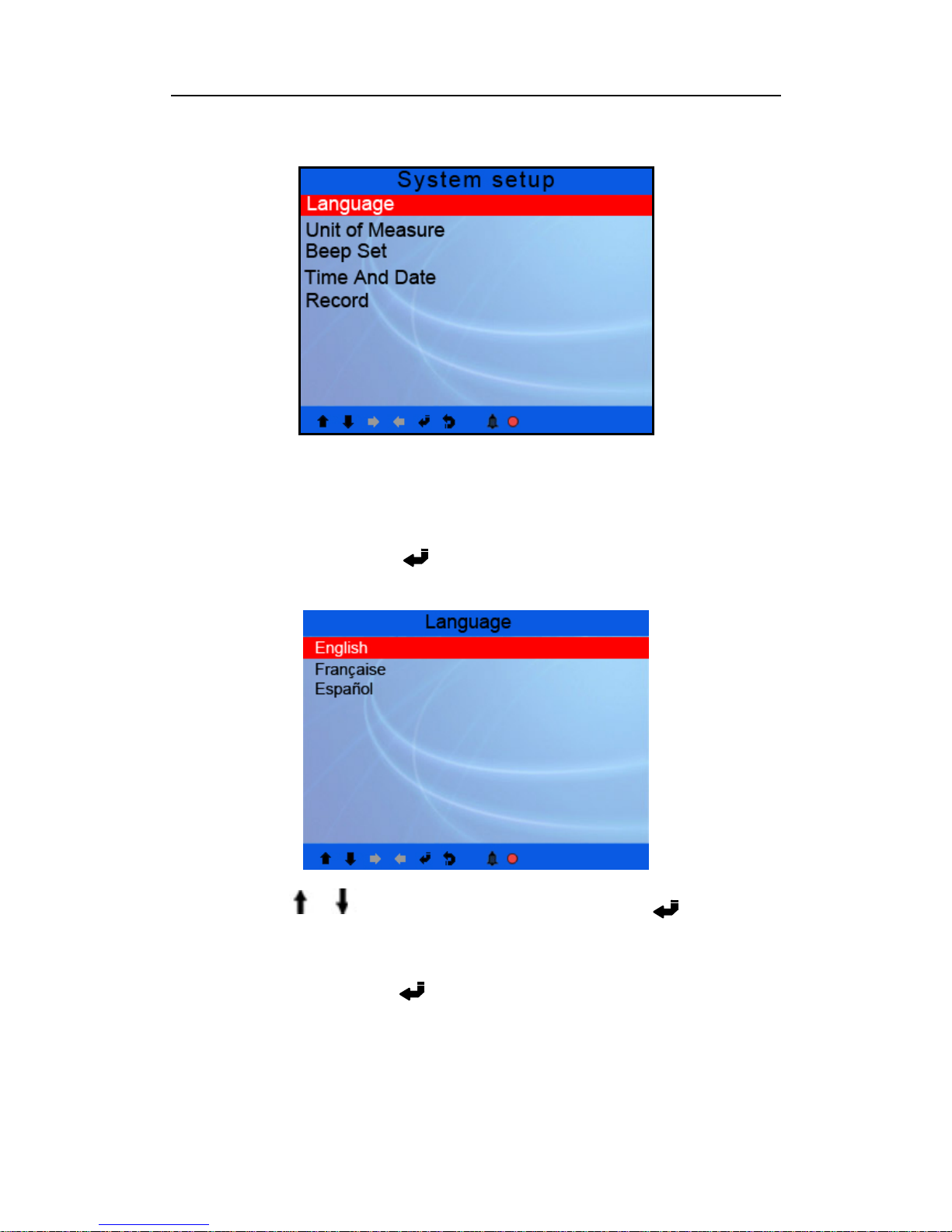
Select [System Setup]
interface as shown below:
10
Page 11
CODESCAN CS602 User’s Manual
Figure 3-2
The CS602 allows you to make the following adjustme nts, settings:
1) Select language: Selects desired language.
Choose [Language] and press [ ], the screen will display the interface as shown
below:
Figure 3-3
You can press [ ] [ ] key to select any language and press [ ] to confirm.
The system will convert to the chosen language interface at once.
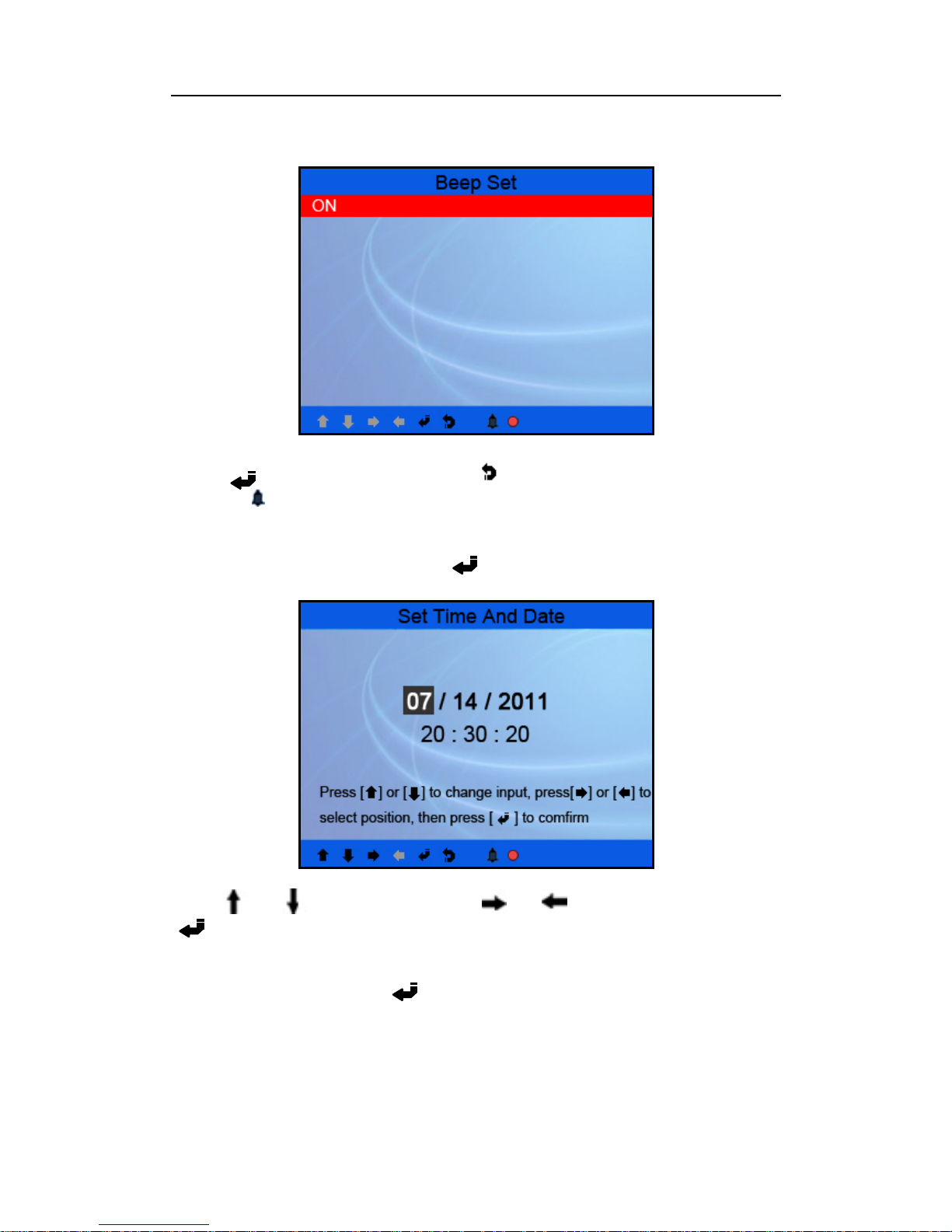
2) Beeper: ON/OFF the Beeper.
Choose [Beep Set] and press [ ], the screen will display the interface as shown
below:
11
Page 12
CODESCAN CS602 User’s Manual
Figure 3-4
Press [ ] to sel ect ON/OF F an d pr ess [ ] to confirm. When this function is ON,
the icon “
” appears,then when you press any button the CS602 will sound.
3)
Time and Date: Set time a nd date.
Choose [Time and Date] and press [ ], the screen will display the interface as
shown below:
Figure 3-5
Press [ ] or [ ] to change input, press [ ] or [ ] to select position, then press
[ ] to confirm.
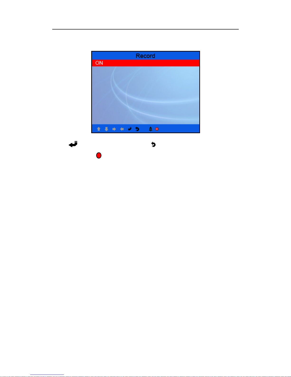
4) Record: ON/OFF the Record.
Choose [Record] and press [ ], the screen will display the interface as shown
below:
12
Page 13
CODESCAN CS602 User’s Manual
Figure 3-6
Press [ ] to select ON/OFF and press [
] to confirm. When this function is
ON, and the icon “ ” app ears, then CS602 can reco rd DTC's , record Datas tream
and record Freeze Frames.
4.6 Vehicle Coverage
The CS602 is specially designed to work with all OBD II compliant vehicles,
including Control Area Network (CAN). It is required by EPA that all 1996 and
newer vehicles (cars and light trucks) sold in the United States must be OBD II
compliant and this includes all American, Asian and European vehicles.
A small number of 1994 and 1995 model year gasoline vehicles are OBD II
compliant. To verify if a 1994 or 1995 vehicle is OBD II compliant, check the
Vehicle Emissions Control Information (VECI) Label, which is located under the
hood or by the radiator of most vehicles. If the vehicle is OBD II compliant, the
label will designate “OBD II Certified”. Additionally, Government regulations
mandate that all OBD II compliant vehicles must have a “common” sixteen-pin Data
Link Connector (DLC ).
For the vehicle to be OBD II compliant it must have a 16-pin DLC (Data Link
Connector) under the dash and the Vehicle Emission Control Information Label must
state that the vehicle is OBD II compliant.
5. OPERATION
5.1 Connection
1) Turn the ignition off.
2) Locate the vehicle’s 16-pin Data Link Connect or (DLC).
13
Page 14
CODESCAN CS602 User’s Manual
3) Plug the OBDII cable into the vehicle’s DLC.
4) Turn the ignition on. E ngine can be off or running.
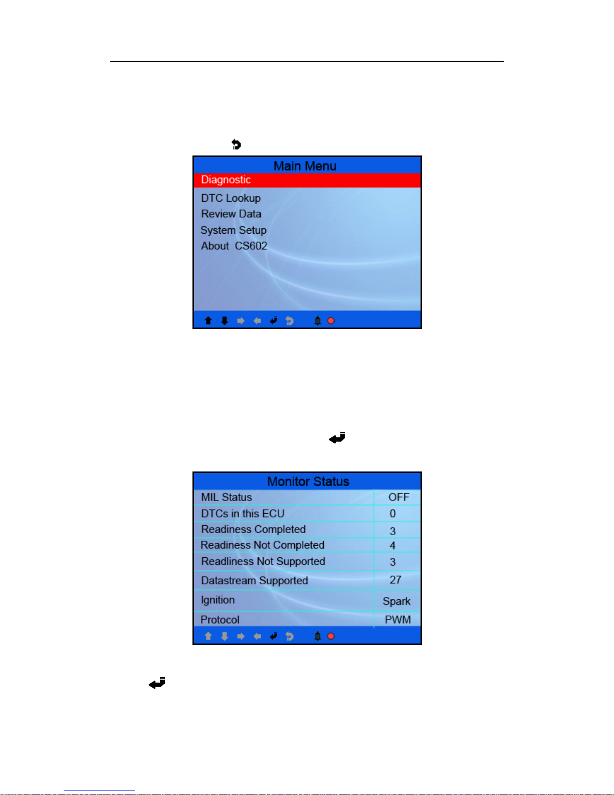
5) After finishing, press [ ] button to enter Main Menu as follow ing figure 4-2:
Figure 4-2
CAUTION: Don’t connect or disconnect any test equipment with ignition on or
engine running.
5.2 Diagnostic
Select [Diagnostic] in Main Menu and press [ ], the screen will display Monitor
Status interface as following figure 4-3:
Figure 4-3
Press [ ] to enter the Main Menu of Diagnostic, the screen will display as
following figure 4-4:
14
Page 15
CODESCAN CS602 User’s Manual
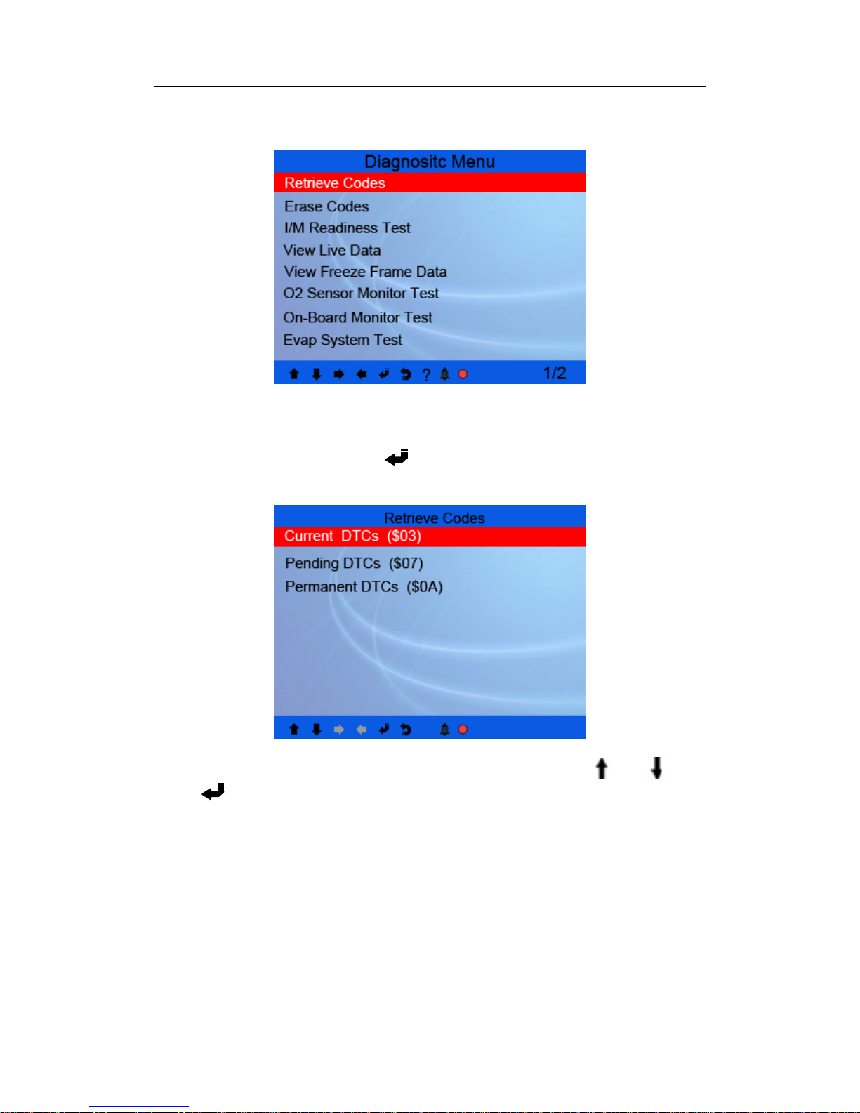
Figure 4-4
5.2.1 Read Codes
Select [Retrieve Codes] and press [ ] in Diagnostic Menu. If there are some codes,
the screen will display the codes as shown below:
Figure 4-5
According to the above figure to select different item by pressing [ ] or [ ] and
press [ ] to confirm
15
Page 16
CODESCAN CS602 User’s Manual
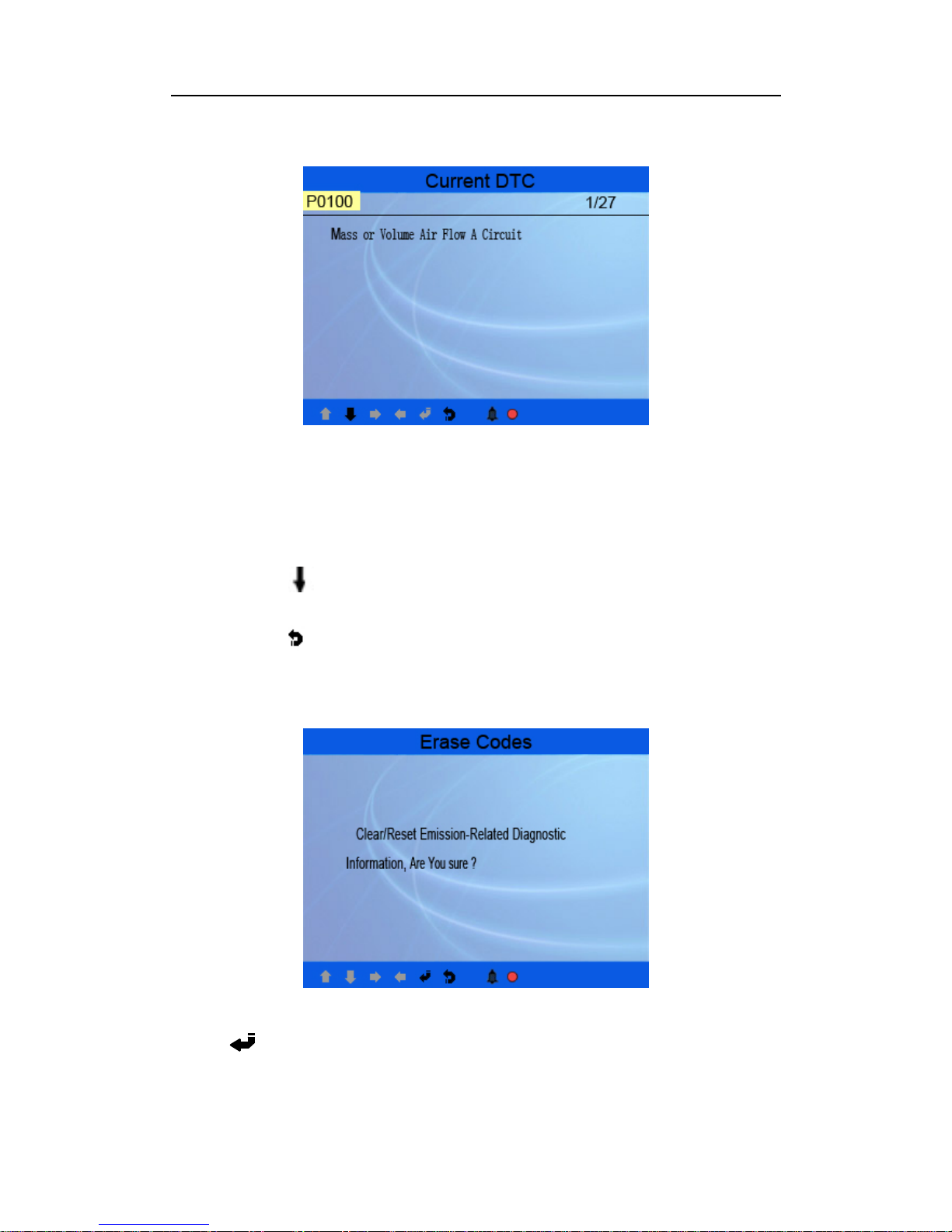
Figure 4-6
1/27 indicates there are 27 codes total and now P0100 is the first code
to display.
The screen will also show the content of the code below the number of
code.
You can use
[ ] key to view the next code.
You can press [ ] to return to the Diagnostic Menu.
5.2.2 Erase Codes
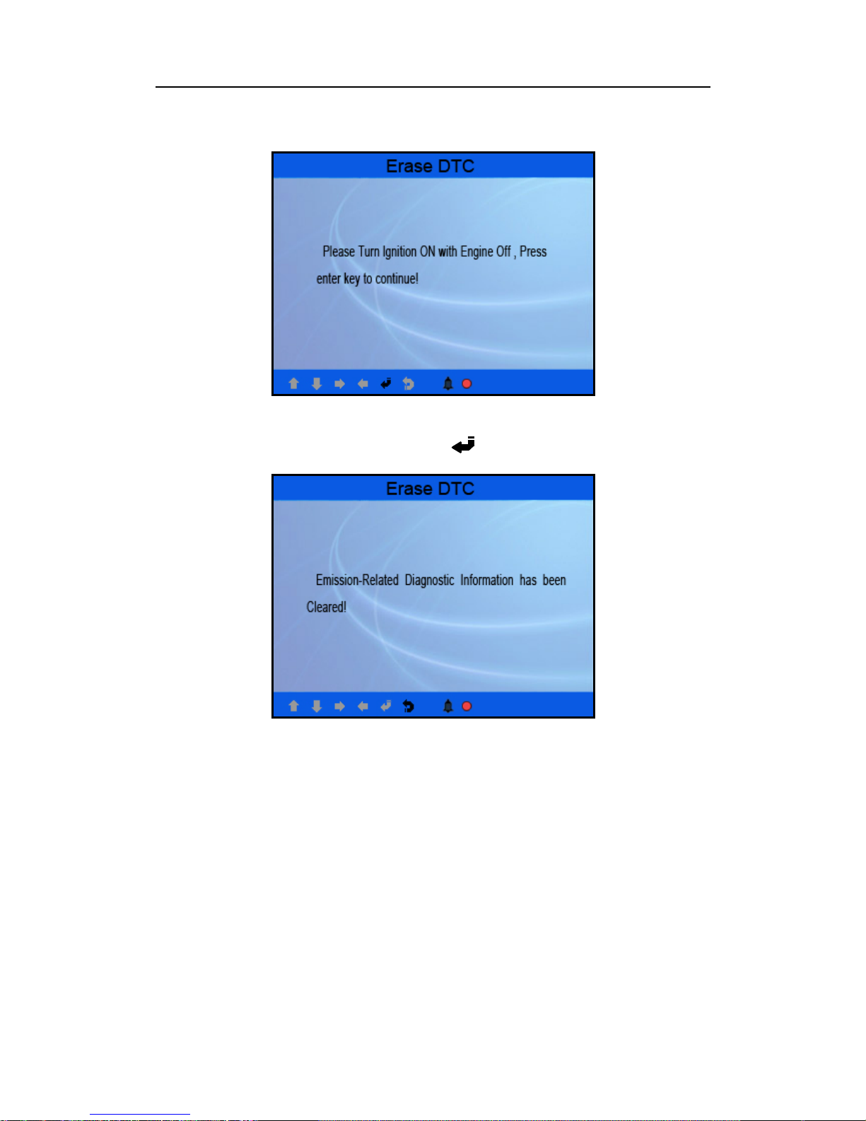
Select [Erase Codes], the screen will display the interface as shown below:
Figure 4-7
Press [ ] to erase DTC’s, and the screen will display the interface as shown
below:
16
Page 17
CODESCAN CS602 User’s Manual
Figure 4-8
According to the above figure to press [ ] and the screen will display the
interface as shown on the next page:
Figure 4-9
Notes:
z Before performing this function, make sure to retrieve and record the
trouble codes.
z After clearing , you sh ould r etri eve tr oub le co d es o nce mo re or tu rn i gni tion
on and retrieve codes again. If there are still some trouble codes in the
system, please troubleshoot the code using a factory diagnosis guide, then
clear the code and recheck.
5.2.3 I/M Readiness
I/M refers to Inspection and Maintenance that is legislated by the Government to
meet federal clean- air st andards. I/M Read iness in dicates wh ether or no t the various
emissions-related systems on the vehicle are operating properly and are ready for
17
Page 18
CODESCAN CS602 User’s Manual
Inspection and Maintena nce testing.
The purpose of the I/M Readiness Monitor Status is to indicate which of the
vehicle’s Monitors have run and completed their diagnosis and testing (as described
in Chapter 2.5), and which ones have not yet run and completed testing and
diagnosis of their designated sections of the vehicle’s emissions system.
The I/M Readiness Monitor Status function also can be used (after repair of a fault
has been performed) to confirm that the repair has been performed correctly, and/or
to check for Monitor Run Status.
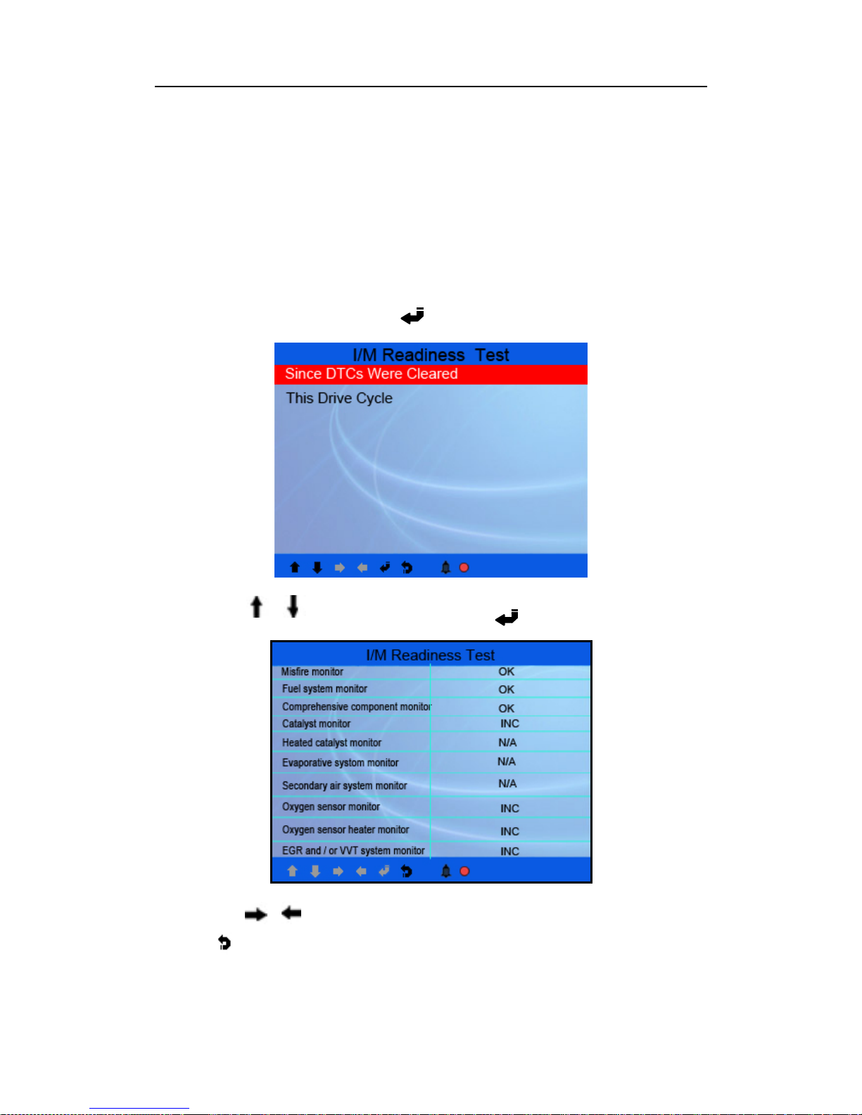
Select [I/M Readiness] and press [ ], the screen will display the interface as
shown below:
Figure 4-10
You can use [ ] [ ] button to select and press [ ], the screen will display the
interface as shown below:
Figure 4-1 1
You can use [ ] [ ] button to view other data of vehicle.
Press [ ] to return to Diagnostic Menu.
N/A means not available on this vehicle, INC means incomplete o r not ready, OK
18
Page 19
CODESCAN CS602 User’s Manual
means Completed or Monitor O k.
5.2.4 Data Stream
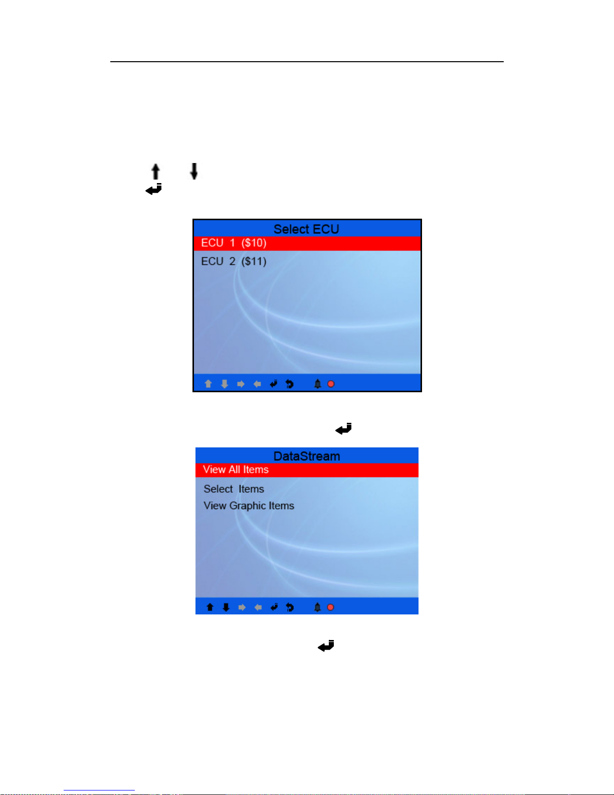
Press [ ] or [ ] button to select Data Stream in Main Menu interface and then
press [ ] button to confirm, the screen will display the interface as shown below:
Figure 4-12
As shown in Figure 4-12 select ECU and press [ ] button, the screen will display
the interface as shown below:
Figure 4-13
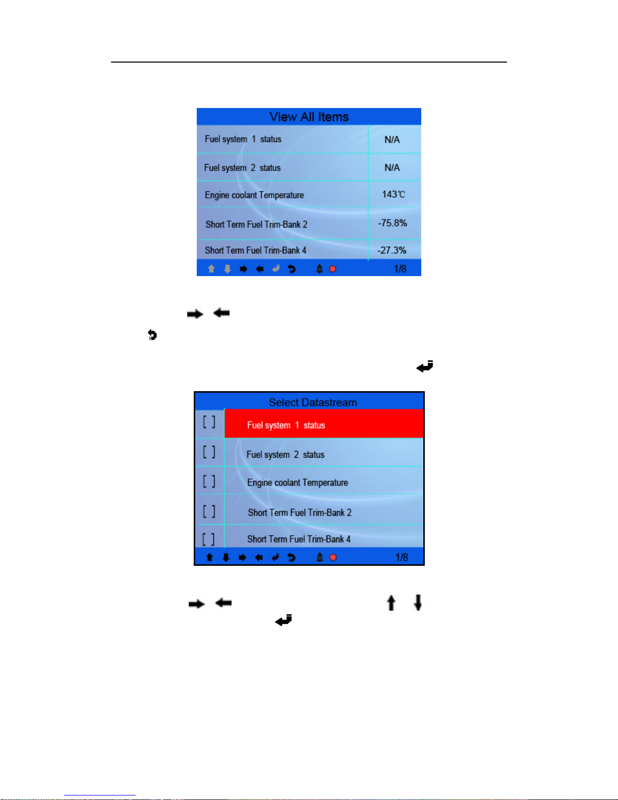
Select [View All Items] and press [ ] button, the screen will display the
interface as shown below:
19
Page 20
CODESCAN CS602 User’s Manual
Figure 4-14
You can use [ ] [ ] button to view other data streams.
Press [
] to return to Diagnostic Menu.
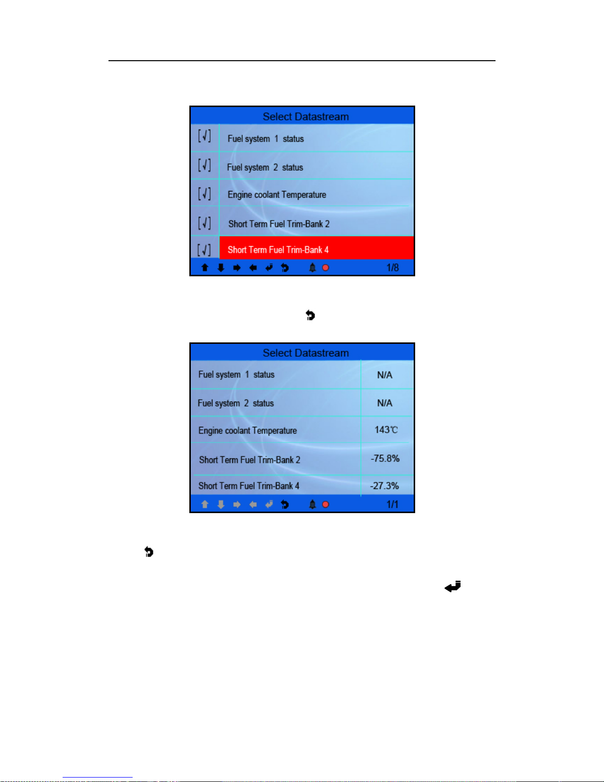
Select [select Items] in Data stream menu and press [ ], the screen
will display the interface as shown below:
Figure 4-15
You can use [ ] [ ] button to turn page, and press [ ] [ ] button to select
data stream items, then press [ ]burron to confirm the selected items, the
screen will display the interface as shown on the next page:
20
Page 21
CODESCAN CS602 User’s Manual
Figure 4-16
After selected items and press
[ ], the screen will display the
interface as shown below:
Figure 4-17
Press [ ] to return to Diagnostic Menu.
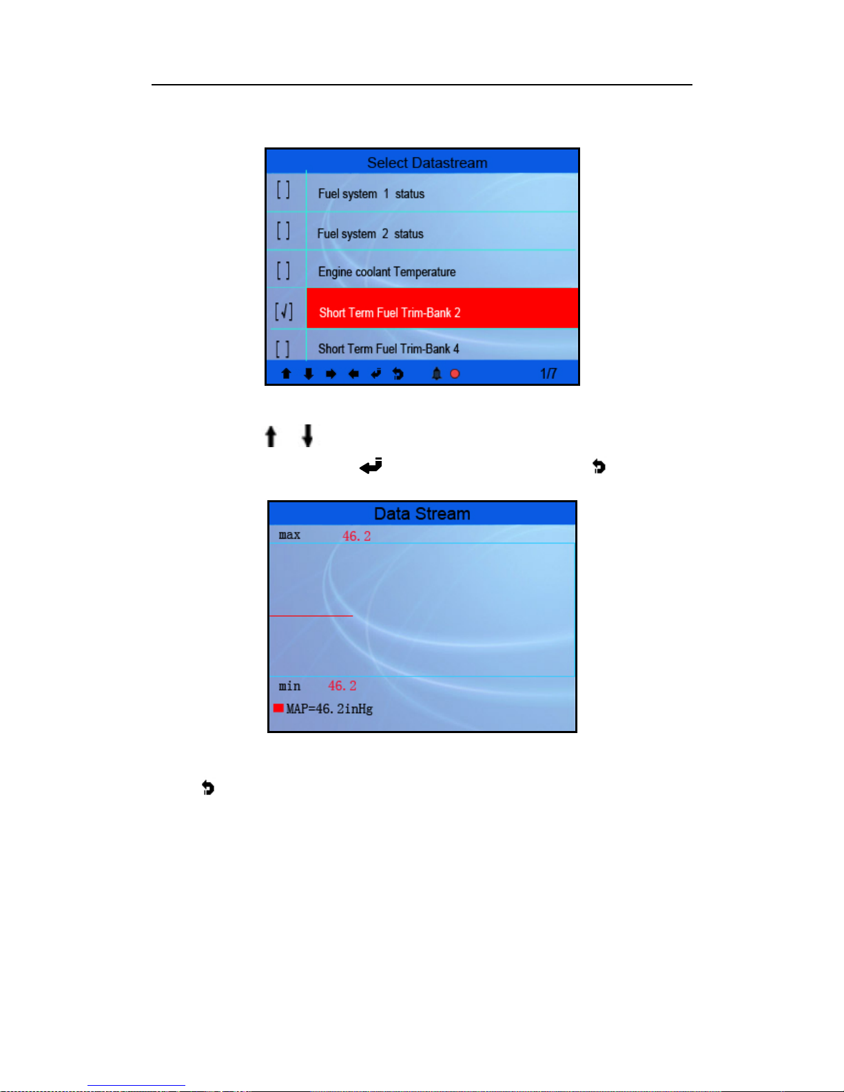
Select [View Graphic Items] in Data stream menu and press
[ ], the
screen will display the interface as shown below:
21
Page 22
CODESCAN CS602 User’s Manual
Figure 4-18
You can use
[ ] [ ] button to select single data stream items to view item of
live data with a graph, and press[ ] button to confirm,then press [
] button, the
screen will display the interface as shown below:
Figure 4-19
Press [ ] to return to Diagnostic Menu.
You can view all data stream items or select a ce rtain item of live data with a graph.
5.2.5 View Freeze Frame
When an emission-related fault occurs, certain vehicle conditions are recorded by
the on-board co mputer. This informatio n is referred to as freeze fr ame data. Freeze
Data is a snapshot of the operating conditions at the time of an emission-related
fault.
22
Page 23
CODESCAN CS602 User’s Manual
Note: if DTCs were erased, Freeze Data may not be stored in vehicle memory
depending on vehicle.
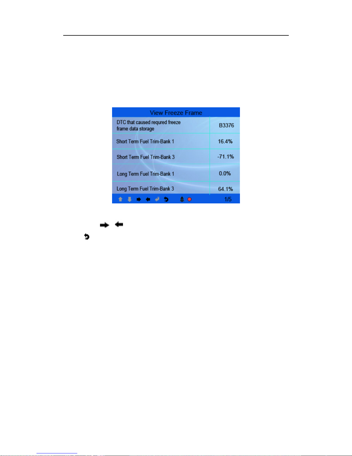
Select [Freeze Frame] in main menu interface, the screen will display the interface
as shown below:
Figure 4-20
You can use [ ] [ ] button to view the data.
Press [ ] to return to Diagnostic Menu.
5.2.6 O2 sensor test
The results of O2 sensor test are not live values but instead the results of the ECU’s
last O2 sensor test. For live O2 sensor readings, refer to any of the live sensor
screens such as Graph Screen.
Not all test values are applicable to all vehicles. Therefore, the list generated will
vary depending on vehicle. In addition, not all vehicles support the Oxygen Sensors
screen.
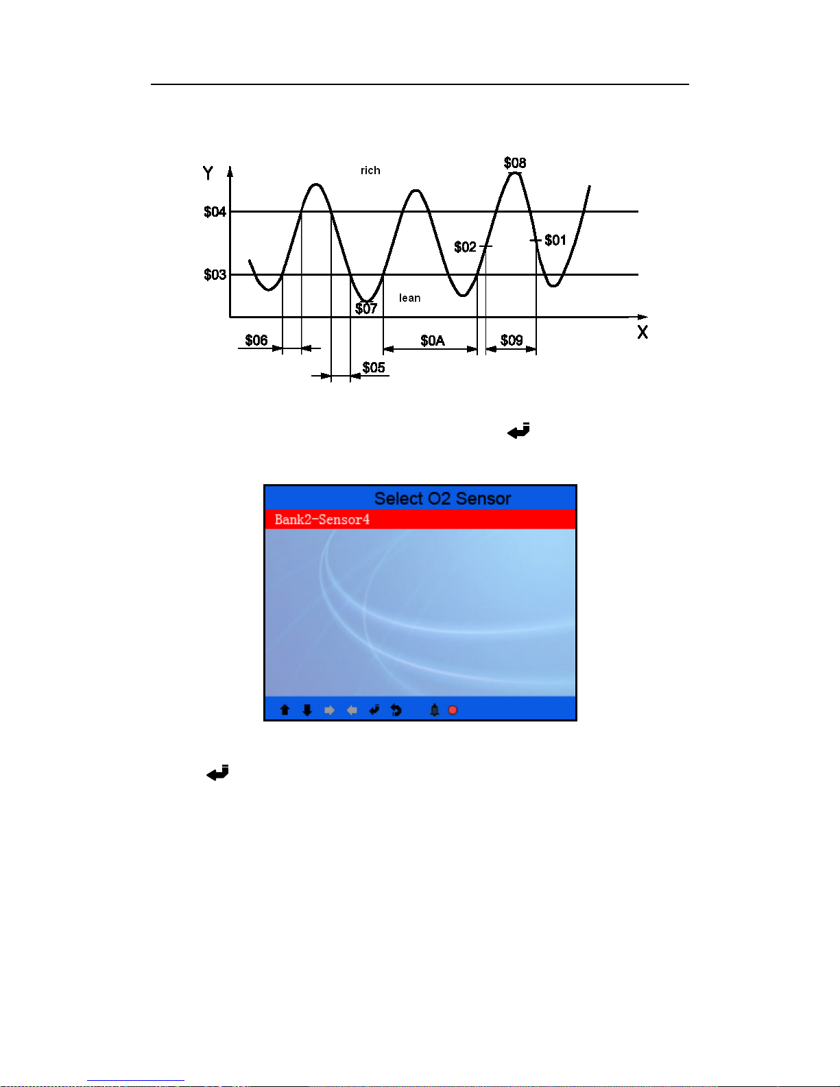
For results of latest mandated on-board oxygen sensor monitoring test, see Figure
4-21 below:
23
Page 24
CODESCAN CS602 User’s Manual
Figure 4-21
Select [O2 Sensor Test] in Diagnostic menu and press [ ] and the screen will
display as shown below:
Figure 4-22
Press [ ] button, the screen will display as shown below:
24
Page 25
CODESCAN CS602 User’s Manual
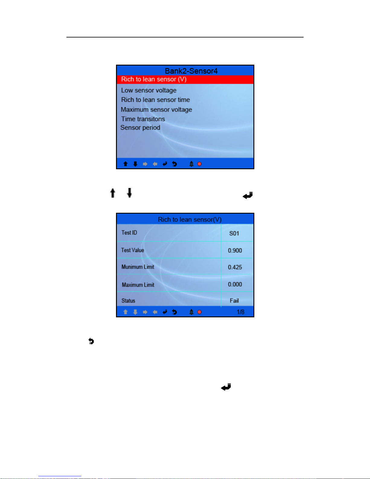
Figure 4-23
You can use [
] [ ] button to select an item and press [ ], the screen will
display as shown below:
Figure 4-24
Press [ ] to return to Diagnostic Menu.
5.2.7 On-board monitor test
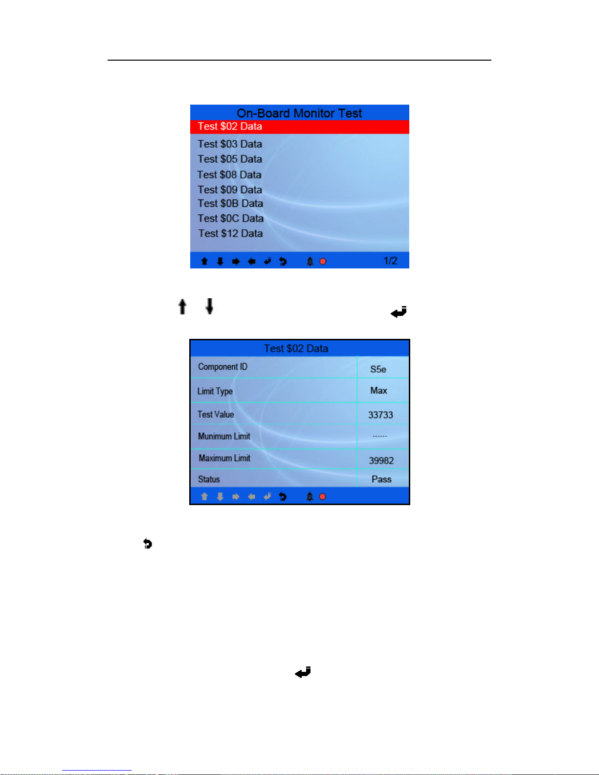
This function can be utilized to read the results of on-board diagnostic monitoring
tests for specific components/systems.
Select [On-board Monitoring] in main menu and press [ ] and the screen will
display as shown below:
25
Page 26
CODESCAN CS602 User’s Manual
Figure 4-25
You can use [ ] [ ] button to select an item and press [ ], the screen will
display as shown below:
Figure 4-26
Press [ ] to return to Diagnostic Menu.
5.2.8 EVAP System Test
The EVAP test function lets you initiate a leak test for the vehicle’s EVAP system.
The CS602 does not perform the leak test, but signals to vehicle’s on-board
computer to initiate the test. Before using the system test function, refer to the
vehicle’s service repair manual to determine the procedures necessary to stop the
test.
Select [EVAP System Test] and press [ ], the screen will display the relative
26
Page 27
CODESCAN CS602 User’s Manual
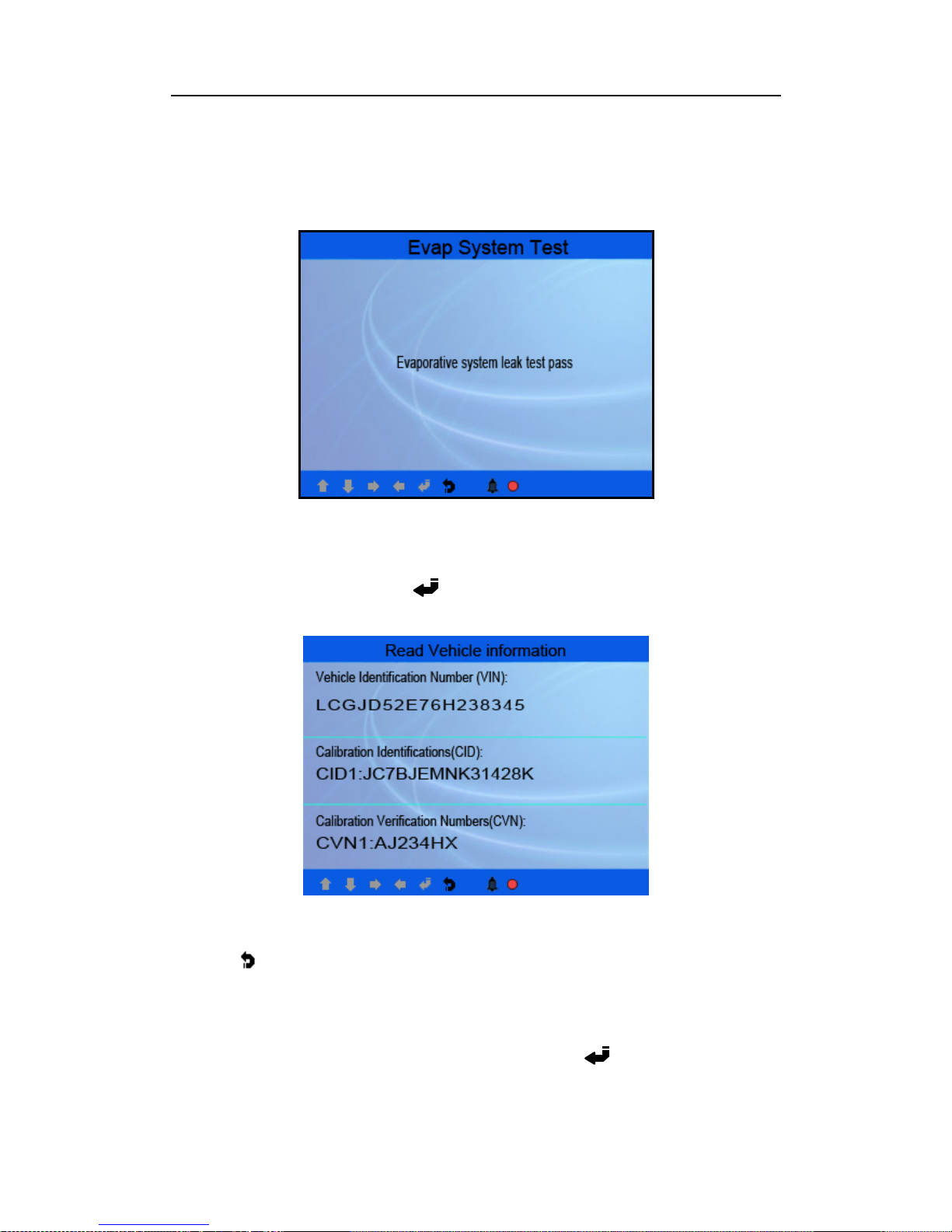
information about EVAP system. Some vehicle manufacturers do not allow external
devices to control vehicle system. If the car supports this function, it will display as
below:
Figure 4-27
5.2.9 Vehicle Info
Select [Vehicle Info] and press [ ], the screen will display the information, such
as VIN (Vehicle identification Number), CID (Calibration ID) and CVN (Calibration
verification number), as shown below:
Figure 4-28
Press [
] to return to Diagnostic Menu.
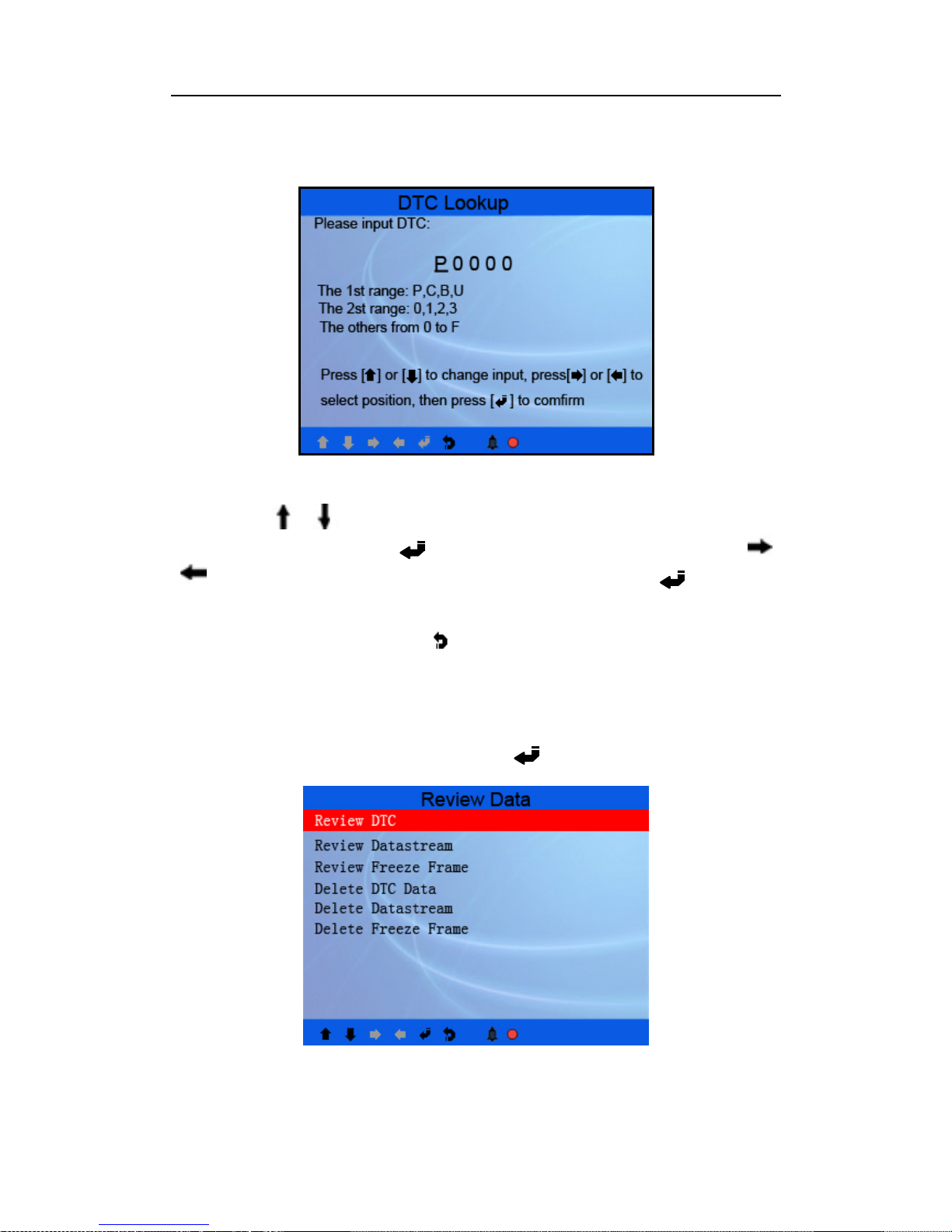
5.3 Code Lookup
Select [Code Lookup] in the Main Menu and press [ ] and the screen will
display the interface as shown below:
27
Page 28
CODESCAN CS602 User’s Manual
Figure 4-29
You can use [
] [ ] key to change the first letter. It can be switched among “P”,
“B”, “C” and “U”. And press [ ] moves the cursor to next. And then press [
]
[ ] key to input number. After you input the code number, press [ ] to view the
definition of the code.
After viewing the definition, press [
] to return to the Main Menu.
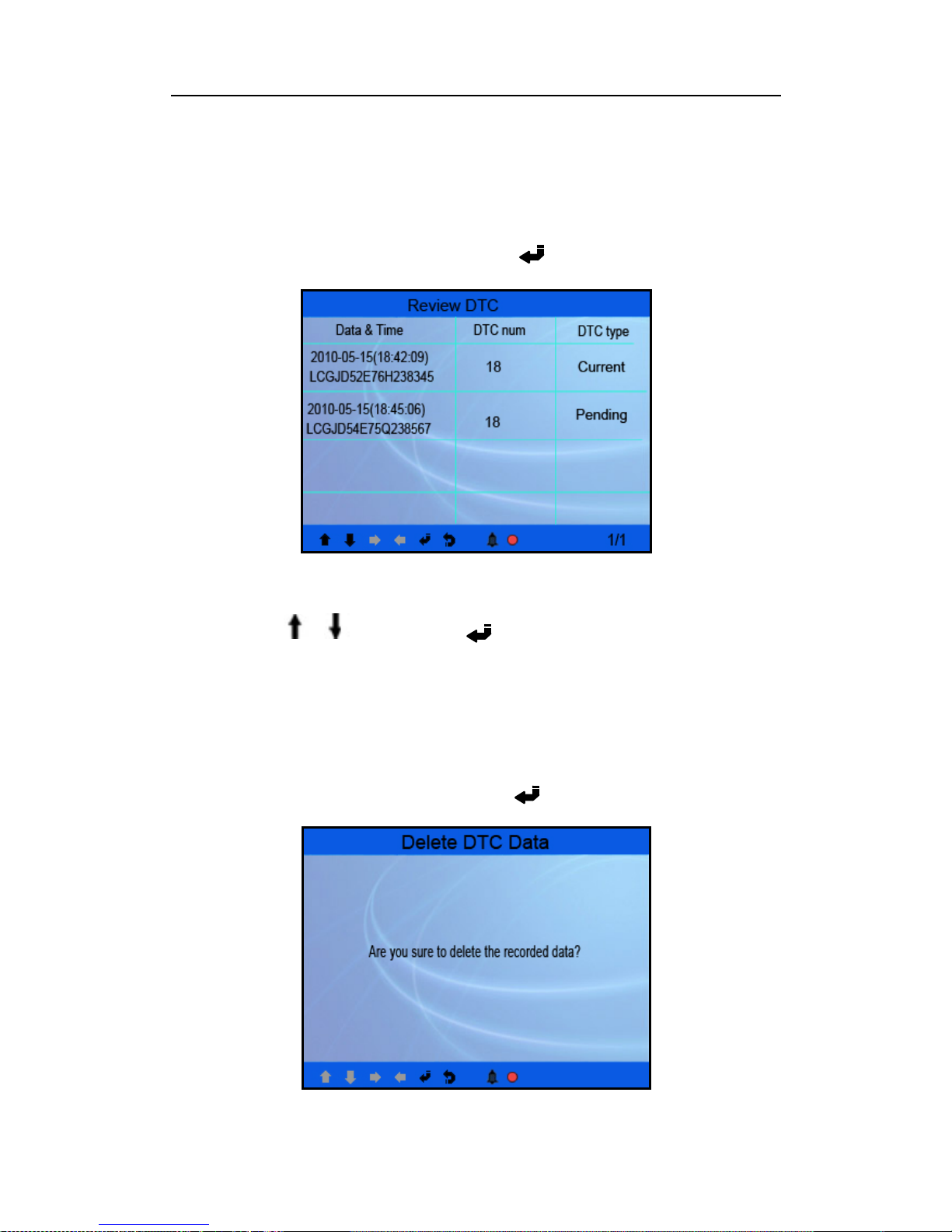
5.4 Review
This function is used to review the recorded Data Streams, DTC, and Freeze Frame.
Select [Review] in the Main Menu and press [ ] and the screen will display the
interface as shown below:
Figure 4-30
28
Page 29
CODESCAN CS602 User’s Manual
CAUTION: About the record function, please view the chapter “4.5 Tool Setup 4)
Record” in page 12.
1) Review DTC
Select [Review DTC] in the Review and press [ ] and the screen will display the
interface as shown below:
Figure 4-31
The recorded DTC will be displayed as shown in Figure 4-31.
You can use [
] [ ] key and press [ ] button to view detailed information,
2) Review Data stream
The operation is similar to the “Review DTC” function.
3) Review Freeze Frame
The operation is similar to the “Review DTC” function.
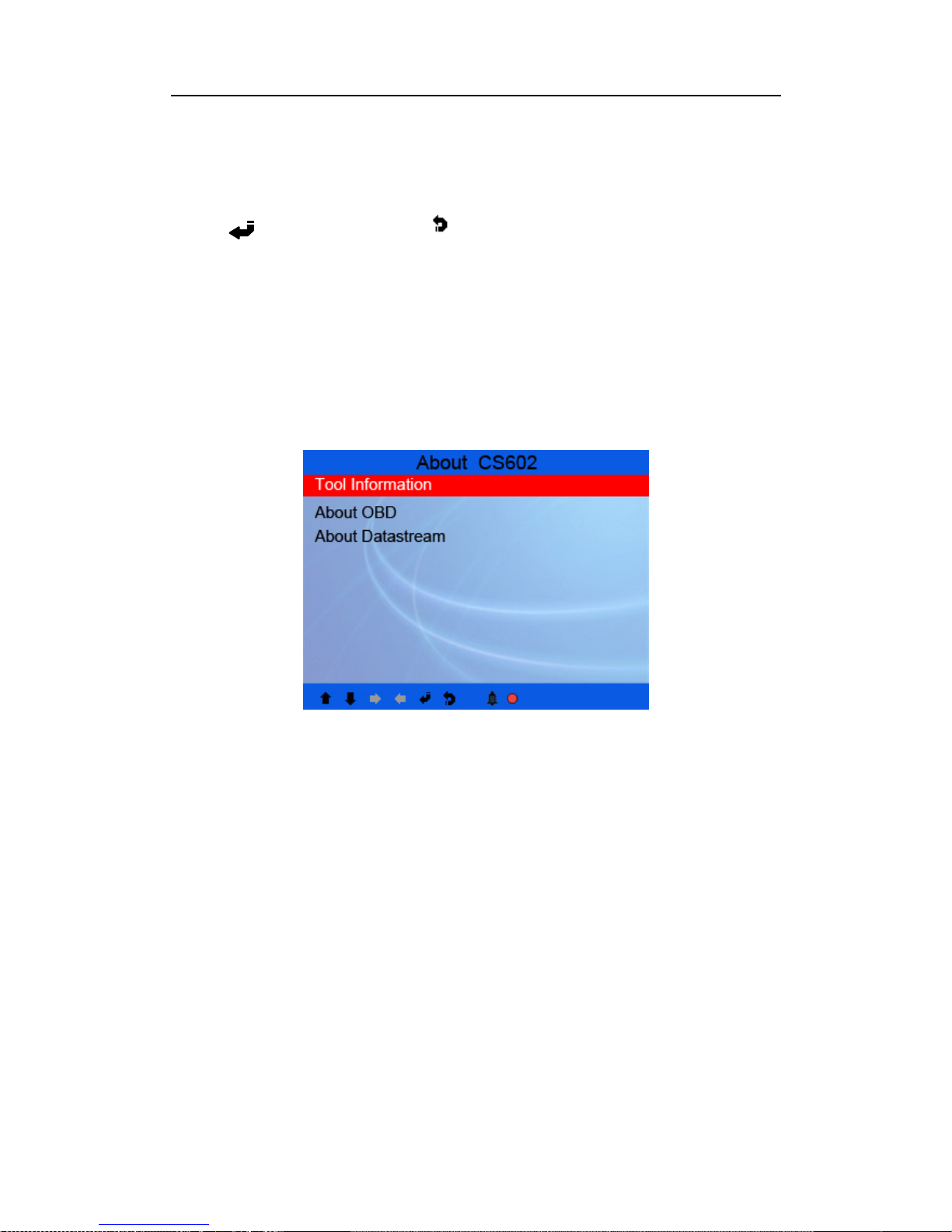
4) Delete DTC
Select [Delete DTC] in the Review and press [ ] and the screen will display the
interface as shown below:
29
Page 30
CODESCAN CS602 User’s Manual
Figure 4-32
Press [ ] to confirm, and press [ ] to return to Main Menu.
5) Delete Data stream
The operation is similar to the “Delete DTC” function.
6) Delete Freeze Frame
The operation is similar to the “Delete DTC” function.
5.5 About CS602
This function is used to view Tool Information, About OBD, and About Data stream.
Figure 4-33
Tool Information includes: software version, hardware version, serial number,
supported, time and date.
About OBD: Relevant introductions information about OBD.
About Data stream: Relevant introduct i ons information about Data stream.
6 FAQ
Here we list some frequently asked questions and answers relating to CS602.
Question: System halts when reading data stream. What is the reason?
Answer: It may be cau sed by a sl ackened conn ector. Please turn off th e Creader VI,
firmly connect the connector, and switch on it again.
30
Page 31

CODESCAN CS602 User’s Manual
Question:
Screen of main unit fla shes at engine ignition sta rt.
Answer:
Caused by electrom agnetic disturbing, and this is normal phenomenon.
Question: There is no response when communicating w ith on-board computer.
Answer:
Please confirm the proper voltage of power supply and check if the throttle
has been closed, the transmission is in the neutral position, and the water is in proper
temperature.
Question: Why are there so many fault codes?
Answer: Usually, it’s caused by poor connection or fault circuit grounding.
Page 32

CODESCAN CS602 User’s Manual
Warranty
THIS WARRANTY IS EXPRESSLY LIMITED TO PERSONS WHO PURCHASE
CODESCAN TOOLS PRODUCTS FOR PURPOSES OF RESALE OR USE IN
THE ORDINARY COURS E OF THE BUYER’S BUSINESS .
CODESCAN TOOLS electronic product is warranted against defects in materials
and workmanship for o ne year (12 months) from date of delivery to the user.
This warranty does not cover any part that has been abused, altered, used for a
purpose other than for which it was intended, or used in a manner inconsistent with
instructions regarding use. The exclusive remedy for any automotive meter found to
be defective is r epair or replacement, a nd CODESCAN TOOLS shall not be liable
for any consequential or incidental damages.
Final determination of defects shall be made by CODESCAN TOOLS in accordance
with procedures established by CODESCAN TOOLS. No agent, employee, or
representative of CODESCAN TOOLS has any authority to bind CODESCAN
TOOLS to any affirmation, representation, or warranty concerning CODESCAN
TOOLS automotive meters, except as stated herein.
Order Information
Replaceable and optional parts can be ordered directly from your CODESCAN
TOOLS authorized tool supplier. Your order should include the following
information:
1. Quantity
2. Part number
3. Item description
Customer Service
If you have any questions on the operation of the unit, please contact local dealer, or
contact CODESCAN TOOLS:
 Loading...