

Page 1
Code Mercenaries
1
LL
LL
EE
EE
DD
DD----
WW
WW
aa
aarrrrrrrriiii
oo
oorrrr
00
00
55
55
1. Features
• Input voltage 7 - 30V
• Constant current output 200mA or 350mA
• Low current ripple version for OLED (<1% Ipp)
• Maximum output power 10W
• Standard variants for 200mA and 350mA
• Custom versions up to 500mA output
• Capable of driving 1..5 white LEDs
• Input transients up to 40V <0.5s
• Up to 96% efficiency
• PWM control input for dimming
• Standby current max. 3.5mA
• Optimized for point-of-load regulation
• Connection options: Crimp, plug, solder
• Surface mounting possible
1.1 Variants
LED-Warrior05 is available in standard variants for
200mA and 350mA output current. The 200mA
variant is a low current ripple version optimized
for driving OLED with <1% Ipp.
Input and output connections are available with the
following options:
Input crimp, output crimp
Input crimp, output plug
Input crimp, output solder
Input solder, output solder
1.2 Custom variants
Custom output current versions are available on
request. Output connectors can be modified.
Thermally conductive adhesive pad for mounting
can be added. Minimum order quantities may
apply.
2. Functional overview
LED-Warrior05 is a point-of-load regulator for
LED lighting applications. By providing a highly
efficient constant current regulation off a DC
source LED-Warrior05 is perfectly suited for
applications that require low DC levels for safety
reasons, driving multiple LED groups in one
luminaire, mobile or in-vehicle lighting, and to
refit existing low voltage halogen installations.
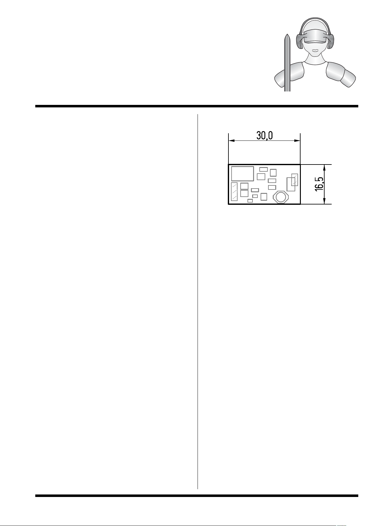
3. Mechanical dimensions
Dimensions in mm
Height at thickest point: 6.5mm
Tolerances:
Outer contour: ±0.2mm
When mounting on a conductive surface make sure
to add spacers or an insulating layer under the
module to avoid short circuits
3.1 Crimp Connectors
The crimp connectors used on the LW05 require a
special crimping tool. Crimping tools can be
pruchased separately.
The connectors are of the AVX/ELCO 00 9175
family. Wires with insulation diameter 0.7 to 1mm
fit into the connectors.
3.2 SMD Mounting
LW05 may be mounted as a SMD part. For details
please contact our support.
V1.0.0 March 21st 2012
HB LED driver module for low
voltage input
Page 2
Code Mercenaries
2
LL
LL
EE
EE
DD
DD----
WW
WW
aa
aarrrrrrrriiii
oo
oorrrr
00
00
55
55
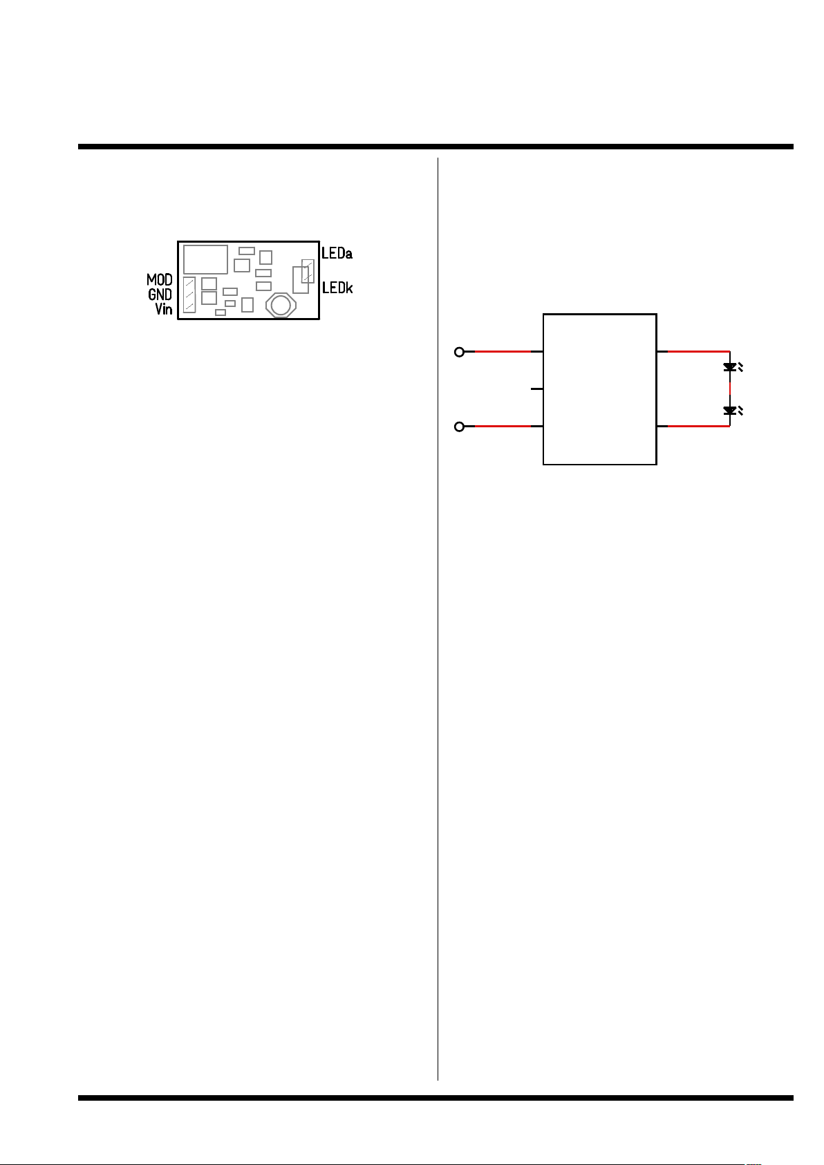
3.3 Pin Descriptions
Vin
Supply voltage positive input. Apply a DC voltage
of 7V to 30V here. The input is protected with a
fuse and a diode to prevent damage from reversed
power supply and safely disconnect the power in
case of a failure.
GND
Supply voltage negative input and ground
reference for MOD input.
LEDa
Positive output for LED, connect the anode of the
first LED of the string to this pin.
LEDk
Negative output for LED, connect the cathode of
the last LED of the string to this pin. This pin is not
identical to GND!
MOD
PWM input. Pulling this pin high shuts off the
output. Feeding a PWM signal with up to 1kHz can
be used to control the brightness of the connected
LEDs. Pulling the pin high permanetly puts LW05
in a standby mode. This pin can be left
unconnected if no brightness control is required.
4. Connecting the LEDs
The maximum number of LEDs that can be driven
by LED-Warrior05 depends on the supply voltage
and the combined forward voltage of the LEDs.
Input voltage needs to be about 2.5V higher than
the total forward voltage of the LED string for
proper operation.
4.1 Reducing output ripple
To reduce output ripple and possibly reduce EMC
problems a capacitor may be put parallel to the
LEDs, preferably connected direct between LEDa
and LEDk of the LED-Warrior05.
The 200mA low ripple version already has such a
capacitor installed on the module to optimise it for
use with OLED.
4.2 EMC
LED-Warrior05 has been designed to produce a
minimal level of EM emissions.
As a component LED-Warrior05 can not be EMC
approved. It has been tested in the configuration of
our AgniLine product and passed with comfortable
margin.
LED1
LEDn
GND
Vin
LEDk
MOD
LEDa
LLLLWWWW000055
55
V1.0.0 March 21st 2012
Page 3

Code Mercenaries
3
LL
LL
EE
EE
DD
DD----
WW
WW
aa
aarrrrrrrriiii
oo
oorrrr
00
00
55
55
5. Brightness control
The MOD input allows PWM dimming of the
LEDs.
By applying a voltage >1V≤Vin the current to the
LEDs is shut off. Frequencies up to about 1kHz
can be applied to the MOD input, though for good
regulator stability it is recommended to not exceed
about 500Hz.
Dimming ranges of about 1% to 100% are possible.
6. Regulator efficiency
The regulator efficieny depends on a number of
parameters. Since there are a couple constant
losses independent of the total power delivered by
the regulator the basic rule is that the regulator is
more efficient when used at higher power (i.e.
more LEDs connected). A lower difference
between input and output voltage does also
increase the efficiency.
6.1 Output current
The output current varies somewhat depending on
the forward voltage of LEDs and the input voltage.
If a more precise output current is required it can
be set by using the MOD input.
0 10 20 30
Input Voltage (V)
70
75
80
85
90
95
100
Efficiency (%)
1 LED
5 LED
3 LED
4LED
2 LED
Efficiency LW05-200
0 10 20 30
Input Voltage (V)
70
75
80
85
90
95
100
Efficiency (%)
2 LED
3 LED
4LED
5 LED
1 LED
Efficiency LW05-350
10 20 30
Input Voltage (V)
0,18
0,2
0,22
0,24
0,26
0,28
0,3
LED Current (A)
3 LED
5 LED
4 LED
2 LED
1 LED
Output Current LW05-200
V1.0.0 March 21st 2012
Page 4

Code Mercenaries
4
LL
LL
EE
EE
DD
DD----
WW
WW
aa
aarrrrrrrriiii
oo
oorrrr
00
00
55
55
6.2 Reliability
The reliability data is based on data provided by
component manufacturers:
Failure Rate (FIT): 1337 * 10-9h
-1
Mean Time to Failure (MTTF): 747943h
7. FCC / CE
The LED-Warrior05 is sold as a module to be
integrated into a device. As such it can not be FCC
or CE approved.
Code Mercenaries has excerted greatest care in
designing this module to minimize RF emission
and assure safe and stable operation. Though the
use of proper cable materials and correct
integration into a device is crucial to assure
product safety and interference free operation.
The integrator who assembles the module into a
device has to take care for appropriate construction
and testing.
10 20 30
Input Voltage (V)
0,28
0,3
0,32
0,34
0,36
0,38
0,4
0,42
0,44
LED Current (A)
3 LED
4 LED
2 LED
5 LED
1 LED
Output Current LW05-350
V1.0.0 March 21st 2012
Page 5

Code Mercenaries
5
LL
LL
EE
EE
DD
DD----
WW
WW
aa
aarrrrrrrriiii
oo
oorrrr
00
00
55
55
8. Absolute maximum ratings
Input Voltage (Vin relative to GND): -40V to +30V (40V for 0.5sec)
MOD pin input voltage (relative to GND): -0.3V to Vin
Input Current: 1A
Operating temperature:
LW05-200: -30°C to +85°C in still air
LW05-350: -30°C to +85°C in still air
Absolute maximum ratings must not be exceeded or permanent damage to the LED-Warrior05 may
result.
8.1 Thermal precautions
When operating at elevated ambient temperature,
vertical mounting in an air volume sufficiently
large to allow convection is recommended to
reduce surface temperature of the regulator.
Additional cooling measures can help to further
reduce the regulator temperature and increase long
term reliability.
No part of the module surface may exceed 125°C
during operation at any time.
8.2 Electrical Characteristics
Input Voltage (Vin): 7V to 30V
Standby current (MOD high): max. 3.5mA
8.3 Failure modes
The most common failure mode seen when the
regulator is destroyed due to overtemperature,
overcurrent, or overvoltage is an internal short
circuit that causes the fuse to disconnect. The fuse
has the ability to disconnect failure currents up to
50A and starts to trip at 1A.
8.4 Recommended safety measures
Materials with low flash points must be kept away
from the regulator. The surface temperature of
parts of the regulator may reach up to 125°C
surface temperature when used at elevated ambient
temperatures and maximum power.
V1.0.0 March 21st 2012
Page 6

Code Mercenaries
6
LL
LL
EE
EE
DD
DD----
WW
WW
aa
aarrrrrrrriiii
oo
oorrrr
00
00
55
55
9. Ordering information
The modules listed here are standard products.
Customized modules are available on request.
9.1 Packaging info
The modules are packaged in boxes of 30 units
each.
9.2 Identifying current values
LED-Warrior05 modules are marked with a color
dot to identify the current value of the module. The
color dot also serves to identify that the module has
been tested and is OK.
The color dot can be found on the input filter
(black square part next to input connector) of the
module. Color codings can be found in the
ordering information table.
Legal Stuff
This document is ©1999-2012 by Code
Mercenaries.
The information contained herein is subject to
change without notice. Code Mercenaries makes
no claims as to the completeness or correctness of
the information contained in this document.
Code Mercenaries assumes no responsibility for
the use of any circuitry other than circuitry
embodied in a Code Mercenaries product. Nor
does it convey or imply any license under patent or
other rights.
Code Mercenaries products may not be used in any
medical apparatus or other technical products that
are critical for the functioning of lifesaving or
supporting systems. We define these systems as
such that in the case of failure may lead to the
death or injury of a person. Incorporation in such a
system requires the explicit written permission of
the president of Code Mercenaries.
Trademarks used in this document are properties of
their respective owners.
Code Mercenaries
Hard- und Software GmbH
Karl-Marx-Str. 147a
12529 Schönefeld
Germany
Tel: +49-3379-20509-20
Fax: +49-3379-20509-30
Mail: support@codemercs.com
Web: www.codemercs.com
HRB 9868 CB
Geschäftsführer: Guido Körber, Christian Lucht
V1.0.0 March 21st 2012
Partname Order Code Color code Description
LED-Warrior05-200
LED-Warrior05-200
LW05-200LRSS
LW05-200LRCC
Red
Red
200mA regulator, low ripple, input solder, output solder
200mA regulator, low ripple, input crimp, output crimp
LED-Warrior05-350
LED-Warrior05-350
LED-Warrior05-350
LED-Warrior05-350
LW05-350SS
LW05-350CS
Orange
Orange
LW05-350CP
LW05-350CC
Orange
Orange
350mA regulator, input solder, output solder
350mA regulator, input crimp, output solder
350mA regulator, input crimp, output plug
350mA regulator, input crimp, output crimp
 Loading...