

Page 1
Code Mercenaries
1
KK
KK
eeeeyyyyWW
WWaaaarrrrrrrriiii
oooorrrr22
22
44
44
DD
DD
1. Features
• USB low speed interface
• Full USB V1.1/2.0 compliance
• Full USB HID 1.1 compliance
• Direct data input for use with microcontrollers
or simple circuits
• Supports all HID keyboard usage codes
• Modifier keys via direct control lines
• Single +5V power supply
• Low power consumption: 20mA max.
• Available as DIL24, SOIC24, and module
2. Functional Overview
KeyWarrior24D is intended for applications where
computer keyboard input has to be generated from
some kind of external data source.
Keystrokes are generated by applying the key code
and modifier key status to the KeyWarrior24D
input lines and then generating a strobe signal.
KeyWarrior24D will send the data as keyboard
input data to the host computer and issue an
acknowledge signal to indicate its readyness for
another code.
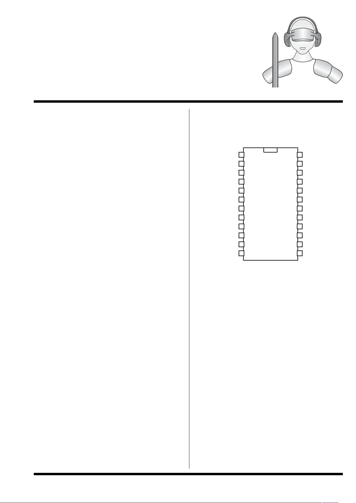
3. Pin Configuration
KeyWarrior24D-P DIL24
KeyWarrior24D-S SOIC24
TOP VIEW!
1
2
3
4
5
6
7
8
9
10
11
12 13
14
15
16
17
18
19
20
DDDD00
00
DDDD11
11
DDDD22
22
DDDD66
66
DDDD33
33
////SSSSTTTTRRRRBB
BB
////RRRR----CCCCttttrrrrll
ll
////AAAACC
C
CKKKK
////LLLL----AAAALLLLTT
TT
////LLLL----GGGGUUUUII
II
GGGGNNNNDD
DD
DDDD++
++
PPPPuuuullllllllTTTTooooGGGGNN
N
NDDDD
DDDD--
--
VVVVrrrreeeegg
gg
VVVVcccccc
cc
HHHHOOOOLLLLDD
DD
NNNNCC
CC
DDDD55
55
DDDD44
44
21
22
23
24
////RRRR----AAAALLLLTT
TT
////RRRR----GGGGUUUUII
II
DDDD77
77
////RRRR----SSSShhhhfffftt
tt
V 1.0.0, December 2nd 2013, for chip revision 1.1.1.D and up
UUUUSSSSBBBB KKKKeeeeyyyybbbbooooaaaarrrrdddd CCCCoooonnnnttttrrrroooolllllllleeeerrrr wwwwiiiitttthhhh ddddiiiirrrreeeecccctttt ddddaaaattttaaaa iiiinnnnppppuuuutt
tt
Page 2
Code Mercenaries
2
KK
KK
eeeeyyyyWW
WWaaaarrrrrrrriiii
oooorrrr22
22
44
44
DD
DD
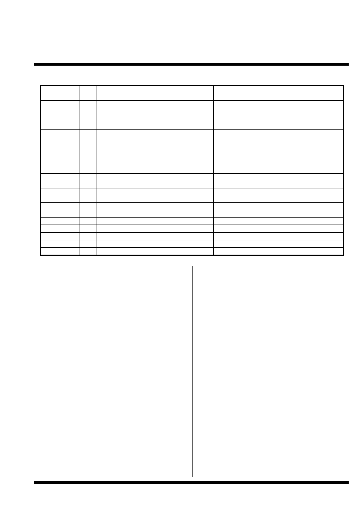
4. Pin Descriptions KeyWarrior24D
4.1 Pin Functions
D+, D-
Differential data lines of USB. Connect these
signals direct to the USB cable or type B plug.
Vreg
Regulated 3V output, to be used only for the
purpose of powering the USB D- pull up resistor.
Do not use this pin as a supply for any other circuit
than the pull up resistor.
D0..D7
Data inputs, the HID usage code for the keystroke
must be put on those lines prior to pulling /STRB
low.
Inputs with internal pull up resistors.
/L-ALT, /L-GUI, /R-Ctrl, /R-Shft, /R-ALT,
R-GUI
Inputs for modifier keys. For ALT and GUI left
and right keys are available, for Ctrl and Shift only
right keys.
Pull an input low to activate the corresponding
modifier key for the next /STRB signal.
Inputs with internal pull up resistors.
/STRB
Strobe input to tell KeyWarrior24D to send a key
code. Pulling this line low triggers KeyWarrior24D
to send the usage code and modifiers as a
keystroke.
Input with internal pull up resistor.
/ACK
Handshake output. This line gets pulled low by
KeyWarrior24D when it has accepted the data on
D0..7 and modifier inputs.
Open drain with internal pull up resistor.
HOLD
Pull this pin high to keep modifier key status active
until next /STRB signal.
Input with internal pull down resistor.
Pull to GND
This pin is used during production of the
KeyWarrior chips, connect to GND.
GND
Power supply ground.
Vcc
Supply voltage.
Name
I/O
Type
Pins
Description
D+, D-
D0, D1, D2,
D3, D4, D5,
D6, D7
I/OIspecial
inputs with internal
pull up resistor
16, 15
1, 2, 3, 4, 24, 23, 22,
21
USB differential data lines
Data input lines for the key code (HID usage code)
/L-ALT,
/L-GUI,
/R-Ctrl,
/R-Shft,
/R-ALT,
/R-GUI
/STRB
/ACK
HOLD
IIinputs with internal
pull up resistor
input with internal pull
up resistor
OIopen drain output with
internal pull up resistor
Input with internal pull
down
6, 19, 7, 18, 8, 17
5
Input lines for the modifier keys. Pull low to
activate modifier
Pull low to signal that keycode data is valid and
should be send
2012Gets pulled low by KW24D to signal that data has
been accepted
Pull high to hold modifier status
PullToGND
GND
Vcc
Vre gIPower supply
O
Power supply
Regulated 3V out
NC-109Used during manufacturing, connect to GND
Ground
1411Supply voltage
Power for D- pullup resistor
13
do not connect
V 1.0.0, December 2nd 2013, for chip revision 1.1.1.D and up
Page 3
Code Mercenaries
3
KK
KK
eeeeyyyyWW
WWaaaarrrrrrrriiii
oooorrrr22
22
44
44
DD
DD
5. Device Operation
KeyWarrior24D registers as a standard HID
keyboard and supports boot protocol. It does not
need any special drivers to be installed, standard
system drivers are sufficient.
The country code is 0 for not localized hardware,
which allows to use a single version of the chip for
all international keyboard layouts. Usage codes are
defined for 0 to 223, which includes all keys and
reserved codes below the modifiers, as well as the
compose keys for Asian languages and several
special keys that may or may not be supported by
individual operating systems.
5.1 Power Up
Every time the supply voltage is applied
KeyWarrior24D executes an internal reset
sequence. All internal pull up resistors are disabled
upon power up and will be activated during the
internal reset sequence.
5.2 How to use KW24D
KeyWarrior24D turns an 8 bit code and six status
lines for modifier keys into a USB keyboard data
report.
To generate a keystroke the HID usage code (see
the "KeyWarrior Scancode Tables" document for a
complete list of the keyboard usage codes) for the
required key is applied to D0..7. The status of any
modifier keys to be combined with this key is indicated by pulling the corresponding pin low.
For example if a capital "A" should be produced
put $04 on D0..7 and pull down /R-Shft.
After applying the data make sure /ACK is high,
then pull down /STRB. /STRB may be pulled low
only when /ACK is high.
Then wait for KeyWarrior24D to pull down /ACK.
This signals that KeyWarrior24D has accepted the
data. Release /STRB and do not pull it low again
until /ACK has returned to high state.
All minimum setup and hold times are 0.
KeyWarrior24D will send the usage code as a short
key press.
5.3 Modifier keys
Modifier keys are input to KeyWarrior24D by
separate control lines. They can be transmitted in
combination with a key code. If only a change of
the status of the modifiers is intended apply a $00
to D0..7, which is the "idle" code for no key
pressed.
If the HOLD input is pulled high the status of the
modifier keys will stay valid until the next status is
passed to KeyWarrior24D on the next falling edge
of /STRB. When HOLD is low (default status due
to internal pull down resistor) the modifier keys
will return to idle after the keystroke.
V 1.0.0, December 2nd 2013, for chip revision 1.1.1.D and up
Page 4

Code Mercenaries
4
KK
KK
eeeeyyyyWW
WWaaaarrrrrrrriiii
oooorrrr22
22
44
44
DD
DD
V 0.0.1, October 8th 2013, for chip revision 1.1.1.D and up
6 DC Characteristics
Code Mercenaries
4
KK
KK
eeeeyyyyWW
WWaaaarrrrrrrriiii
oooorrrr22
22
44
44
DD
DD
V 1.0.0, December 2nd 2013, for chip revision 1.1.1.D and up
6. DC Characteristics
6.1 AC Characteristics
6.2 Absolute Maximum Ratings
Storage Temperature -65°C to +150°C
Ambient Operating Temperature 0°C to +70°C
Supply Voltage on Vcc relative to Vss -0.5V to +7.0V
DC Input Voltage -0.5V + Vcc + 0.5V
Max. Output Current into any Pin 70mA
Power Dissipation 300mW
Static Discharge Voltage >2000V
Latch-up Current >200mA
Parameter Min Max Units Remarks
V
cc
I
cc
Operating Voltage
Operating Supply Current
4.35 5.25
20
V
mA
I
sb
I
ol
I
ol
R
up
Suspend mode current
Max sink current on output pins
Sink current on output pins
Pull-up Resistance 8
25
70
μA
mA
2
24
mA
kΩ
Oscillator off
Cummulative across all ports
Vout = 0.4V
V
ith
V
H
V
oh
Input threshold voltage
Input hysteresis voltage
40%
3%
USB Interface
Static output high 2.8
V
ol
V
di
V
cm
V
se
Static output low
Differential Input sensitivity 0.2
Differential Input common Mode Range
Single Ended Transceiver Threshold
0.8
0.8
60%
10%
V
cc
V
cc
3.6 V
All ports, low to high edge
15kΩ±5% to GND
0.3 V
V
2.5
2.0
V
V
|(D+)-(D-)|
C
in
I
io
R
pu
R
pd
Transceiver capacitance
Hi-Z State Data Line Leakage -10
Bus Pull-up resistance
Bus Pull-down resístance
1.274
14.25
20
10
pF
μA
15.75
15.75
kΩ
kΩ
0V < Vin < 3.3V, Hi-Z State
1.3kΩ±2% to Vreg
15kΩ±5%
Parameter Min Max Units Remarks
clock accuracy
USB Driver Characteristics
-1.5 +1.5 % Derived from USB signal
t
r
t
r
t
f
t
f
Transition rise time
Transition rise time
75
Transition fall time
Transition fall time
75
300
ns
ns
300
ns
ns
CLoad = 200pF
CLoad = 600pF
CLoad = 200pF
CLoad = 600pF
t
rfm
V
crs
t
drate
Rise/Fall Time matching
Output signal crossover voltage
80
1.3
USB Data Timing
Low Speed Data Rate 1.4775
t
djr1
t
djr2
t
deop
t
eopr2
Receiver data jitter tolerance
Receiver data jitter tolerance
-75
-45
Differential to EOP transition skew
EOP width at reeiver
-40
670
125
2.0
%
V
1.5225 MBit/s
75
45
ns
ns
100 ns
ns
To next transition
For paired transitions
Accepts as EOP
t
eopt
t
udj1
t
udj2
Source EOP width
Differential driver jitter
1.25
-95
Differential driver jitter -150
1.50
95
μs
ns
150 ns
To next transition
To paired transition
Page 5

Code Mercenaries
5
KK
KK
eeeeyyyyWW
WWaaaarrrrrrrriiii
oooorrrr22
22
44
44
DD
DD
7. Ordering Information
7.1 Shipping info
DIL24 chips come in tubes of 16 each. SOIC24
chips come in tubes of 31 each.
To assure the safest handling we recommed that
you order in multiples of full tubes.
Custom chips can be ordered in full tubes only!
SOIC24 chips are shipped in a moisture barrier bag
when ordered in a minimum quantity of one full
tube.
7.2 USB VendorID and ProductID
By default all KeyWarrior chips are shipped with
the USB VendorID of Code Mercenaries ($7C0 or
decimal 1984).
The ProductID will be assigned by Code
Mercenaries.
On request chips can be equipped with the
customers VendorID and ProductID. VendorIDs
can be obtained from the USB Implementers
Forum <www.usb.org>
The ProductID for the standard KeyWarrior24D
chips is:
KeyWarrior24D $0223
ProductIDs are independent of the package type.
Partname Order Code Description Package
KeyWarrior24D
KeyWarrior24D
KW24D-P
KW24D-S
Digital input keyboard controller
Digital input keyboard controller
PDIP24
SOIC24
KeyWarrior24D KW24D-MOD Digital input keyboard controller, ready to use module Module
V 1.0.0, December 2nd 2013, for chip revision 1.1.1.D and up
Page 6

Code Mercenaries
6
KK
KK
eeeeyyyyWW
WWaaaarrrrrrrriiii
oooorrrr22
22
44
44
DD
DD
V 0.0.1, October 8th 2013, for chip revision 1.1.1.D and up
8 External circuit for KeyWarrior24D
Code Mercenaries
6
KK
KK
eeeeyyyyWW
WWaaaarrrrrrrriiii
oooorrrr22
22
44
44
DD
DD
8. External circuit for KeyWarrior24D
GND
D+
D-
+5V
4
3
2
1
R1
1K3
C1
100nF
D+
D-
D0
D1
D2
D3
D4
D5
D6
D7
/STRB
/ACK
/L-ALT
/L-GUI
VssVpp
Vcc
NC
HOLD
KKKKWWWW22224444DD
DD
VREG
/R-GUI
/R-ALT
/R-Shft
/R-Ctrl
11
17
8
18
7
16
15
13
12
1
2
3
4
24
23
22
21
20
6
19
5
V 1.0.0, December 2nd 2013, for chip revision 1.1.1.D and up
Page 7

Code Mercenaries
7
KK
KK
eeeeyyyyWW
WWaaaarrrrrrrriiii
oooorrrr22
22
44
44
DD
DD
9. Package Dimensions
24 Pin DIL
24 Pin SOIC
V 1.0.0, December 2nd 2013, for chip revision 1.1.1.D and up
Page 8

Code Mercenaries
8
KK
KK
eeeeyyyyWW
WWaaaarrrrrrrriiii
oooorrrr22
22
44
44
DD
DD
10. ESD Considerations
KeyWarrior has an internal ESD protection to
withstand discharges of more than 2000V without
permanent damage. However ESD may disrupt
normal operation of the chip and cause it to exhibit
erratic behaviour.
For the typical office environment the 2000V
protection is normally sufficient. Though for
industrial use additional measures may be
necessary.
When adding ESD protection to the signals special
care must be taken on the USB signal lines. The
USB has very low tolerance for additional
resistance or capacitance introduced on the USB
differential signals.
10.1 EMC Considerations
KeyWarrior uses relatively low power levels and
so it causes few EMC problems.
To avoid any EMC problems the following rules
should followed:
• Put a 100nF ceramic capacitor right next to the
power supply pins and make sure the PCB
traces between the chips power pins and the
capacitor are as short as possible.
• Run the power supply lines first to the capacitor,
then to the chip.
• Make the signal lines only as long as absolutely
necessary.
Adding a ferrite bead to the +5V and ground power
supply lines is advisable.
11. Revision History
This is a supplemental data sheet to the
KeyWarrior data sheet. Please refer to the main
data sheet for the revision history.
V1.1.1.D is the inital release version of the
KeyWarrior24D.
12. RoHS compatibility
RoHS compatible parts are indicated by a "R"
being appended to the version number.
I.e. a KeyWarrior24D in DIL24 package will have
a marking as follows if it is RoHS compatible:
KW24D-P
V1.1.1.DR
Legal Stuff
This document is ©1999-2013 by Code
Mercenaries Hard- und Software GmbH.
The information contained herein is subject to
change without notice. Code Mercenaries makes
no claims as to the completeness or correctness of
the information contained in this document.
Code Mercenaries assumes no responsibility for
the use of any circuitry other than circuitry
embodied in a Code Mercenaries product. Nor
does it convey or imply any license under patent or
other rights.
Code Mercenaries products may not be used in any
medical apparatus or other technical products that
are critical for the functioning of lifesaving or
supporting systems. We define these systems as
such that in the case of failure may lead to the
death or injury of a person. Incorporation in such a
system requires the explicit written permission of
the president of Code Mercenaries.
Trademarks used in this document are properties of
their respective owners.
Code Mercenaries
Hard- und Software GmbH
Karl-Marx-Str. 147a
12529 Schönefeld
Germany
Tel: +49-3379-20509-20
Fax: +49-33790-20509-30
Mail: support@codemercs.com
Web: www.codemercs.com
HRB 9868 CB
Geschäftsführer: Guido Körber, Christian Lucht
V 1.0.0, December 2nd 2013, for chip revision 1.1.1.D and up
 Loading...