

Page 1
Code Mercenaries
1
KK
KK
eeeeyyyyWW
WWaaaarrrrrrrriiii
oooorrrr22
22
44
44
1. Features
• USB low speed interface
• Full USB V1.1/2.0 compliance
• Full USB HID 1.1 compliance
• 64 keys in 8x8 matrix or three incremental
encoders and 9 keys
• Media control and application keys supported
• Two function shift keys to switch to a second
and third key table
• Up to 34 macros with up to 31 keys each
• Factory programmed keyboard layout
• Custom chips for volume production
• Support for Caps lock, Num lock and Scroll
lock LEDs on matrix chips
• Single +5V power supply
• Low power consumption: 40mA max.
• Available in 24 pin DIL and SOIC
1.1 Variants
KeyWarrior24 are available in three factory
programmed versions with a fixed keyboard
layout.
KeyWarrior24-8 and KeyWarrior24-8M support a
8x8 key matrix.
KeyWarrior24-8 is preprogrammed with general
keyboard layouts.
KeyWarrior24-8M is preprogrammed with media
control keys like "Mute", "Play/Pause" etc. and
general keyboard layouts.
KeyWarrior24-S3 supports nine direct connected
keys and three incremental encoders to produce
key strokes from jog wheels and similar devices.
KeyWarrior24-S3 is preprogammed with media
controls and other keys typically used for jog
wheels.
Custom variants are available for production
volumes.
KeyWarrior24-8
• Supports up to 64 keys in 8x8 matrix
• Preprogrammed with three layouts for general
use, POS, and gaming
• Support for Caps lock, Num lock and Scroll
lock LEDs
• Supports diodes in the key matrix
KeyWarrior24-8M
• Supports up to 64 keys in 8x8 matrix
• Preprogrammed with three layouts for media
control and general use
• Supports Mute, Eject, Play/Pause, Forward,
Backward,
• Support for Caps lock, Num lock and Scroll
lock LEDs
• Supports diodes in the key matrix
KeyWarrior24-S3
• Supports three incremental encoders
• Encoder pulses turned into key strokes
• Supports nine direct connected keys
• Supports Mute, Eject, Play/Pause, Forward,
Backward,
• Preprogrammed for media control and general
use
2. Functional Overview
KeyWarrior24 is a low cost variant of the
KeyWarrior family. It is primarily designed to
reduce hardware requirements and costs for
smaller keyboard designs that don't need the
complexity of the main KeyWarrior family line.
KeyWarrior24 supports USB only and uses a
factory programmed keyboard layout. This reduces
the external circuitry to almost zero.
The standard KeyWarrior24 chips are available as
off the shelf standard parts with a fixed keyboard
layout. For production volumes (>100) it is
possible to order KeyWarrior24 with a custom key
layout, including up to 34 macros.
KeyWarrior24 implements the KeyWarrior
Commander macro function, restricting the number
of macros to 34 (instead of 48), while retaining all
the other options, like using up to 31 keycodes per
macro and assigning each of the macros to any of
the 64 keys or three encoders and nine keys and
any of the three FN-levels.
V 1.1.2, December 2nd 2013, for chip revision 1.1.1.4/1.1.1.B and up
FFFFiiiixxxxeeeedddd PPPPrrrrooooggggrrrraaaammmm UUUUSSSSBBBB KKKKeeeeyyyybbbbooooaaaarrrrdddd CCCCoooonnnnttttrrrroooolllllllleeeerrrr FFFFaaaammmmiiiillllyy
yy
SSSSuuuupppppppplllleeeemmmmee
ee
nnnntttt ttttoooo tttthhhheeee KKKKeeeeyyyyWWWWaaaarrrrrrrriiiioooorrrr DDDDaaaattttaaaa SSSShhhheeeeeeeett
tt
Page 2
Code Mercenaries
2
KK
KK
eeeeyyyyWW
WWaaaarrrrrrrriiii
oooorrrr22
22
44
44
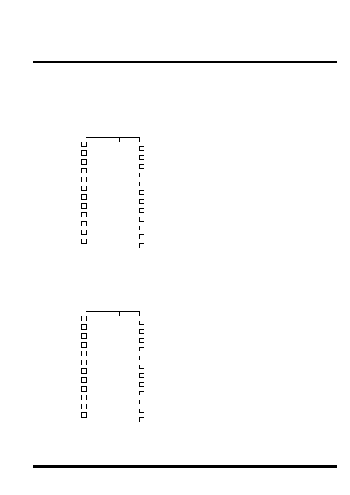
3. Pin Configuration
KeyWarrior24-8-P
KeyWarrior24-8M-P
DIL24
KeyWarrior24-8-S
KeyWarrior24-8M-S
SOIC24
KeyWarrior24-S3-P
DIL24
KeyWarrior24-S3-S
SOIC24
TOP VIEW!
1
2
3
4
5
6
7
8
9
10
11
12 13
14
15
16
17
18
19
20
YYYY00
00
YYYY11
11
YYYY22
22
YYYY66
66
YYYY33
33
XXXX0000////SSSSccccrrrroooollllll
ll
XXXX44
44
XXXX1111////NN
NN
uuuumm
mm
XXXX2222////CCCCaaaappppss
ss
XXXX33
33
GGGGNNNNDD
DD
DDDD++
++
PPPPuuuullllllllTTTTooooGGGGNNNNDD
DD
DD
D
D----
VVVVrrrreeeegg
gg
VVVVcccccc
cc
NNNNCC
CC
NNNNCC
CC
YYYY55
55
YYYY44
44
21
22
23
24
XXXX66
66
XXXX77
77
YYYY77
77
XXXX55
55
1
2
3
4
5
6
7
8
9
10
11
12 13
14
15
16
17
18
19
20
AAAA00
00
BBBB00
00
AAAA11
11
SSSSwwww88
88
BBBB11
11
SSSSwwww00
00
SSSSwwww44
44
SSSSwwww11
11
SSSSwwww22
22
SSSSww
ww3333
GGGGNNNNDD
DD
DDDD++
++
PPPPuuuullllllllTTTTooooGGGGNNNNDD
DD
DDDD--
--
VVVVrrrreeeegg
gg
VVVVcccccc
cc
FFFFu
uuullllll
ll
NNNNCC
CC
BBBB22
22
AAAA22
22
21
22
23
24
SSSSwwww66
66
SSSSwwww77
77
////EEEEnn
nn
SSSSwwww55
55
V 1.1.2, December 2nd 2013, for chip revision 1.1.1.4/1.1.1.B and up
Page 3
Code Mercenaries
3
KK
KK
eeeeyyyyWW
WWaaaarrrrrrrriiii
oooorrrr22
22
44
44
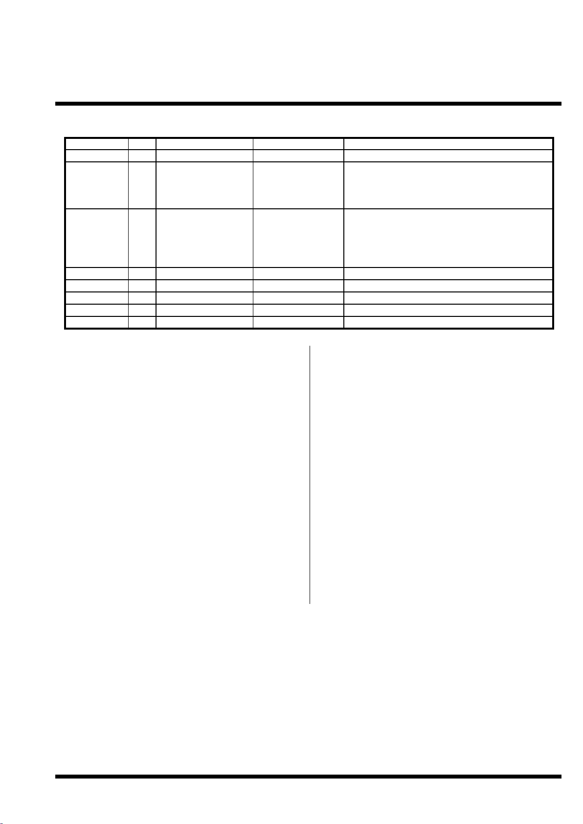
4. Pin Descriptions KeyWarrior24-8/KeyWarrior24-8M
4.1 Pin Functions KeyWarrior24-8/8M
D+, D-
Differential data lines of USB. Connect these
signals direct to the USB cable or type B plug.
Vreg
Regulated 3V output, to be used only for the
purpose of powering the USB D- pull up resistor.
Do not use this pin as a supply for any other circuit
than the pull up resistor.
X0/Scroll, X1/Num, X2/Caps, X[3:7]
Matrix horizontal inputs. These eight lines are read
by KeyWarrior to detect pressed keys.
X0, X1, X2 are also used to drive the Scroll, Num,
and Caps Lock LEDs. An external driver transistor
is required for each LED (see application circuit).
The LEDs will glow faintly when a key on the
same row is pressed.
Internal pull up resistors are activated on device
reset.
Y[0:7]
Vertical matrix outputs. These open drain outputs
are periodically pulled low to detect pressed keys.
No internal or external pull up resistors.
Pull to GND
This pin is used during production of the
KeyWarrior chips, connect to GND.
GND
Power supply ground.
Vcc
Supply voltage.
Name
I/O
Type
Pins
Description
D+, D-
Y0, Y1, Y2,
Y3, Y4, Y5,
Y6, Y7
I/OOspecial
open drain outputs
16, 15
1, 2, 3, 4, 24, 23, 22,
21
USB differential data lines
Y lines for key matrix. These lines are periodically
pulled low, between matrix scan they are high
impedance.
X0/Scroll,
X1/Num,
X2/Caps, X3,
X4, X5, X6,
X7
PullToGND
GND
Vcc
I/OIinputs with internal
pull ups, X0, X1, X2
open drain I/O
Power supply
Power supply
5, 20, 6, 19, 7, 18, 8,
17
10
X lines for key matrix. Between matrix scan X0,
X1, X2 are used as outputs for the keyboard LEDs
Used during manufacturing, connect to GND
914Ground
Supply voltage
Vre gNCO-Regulated 3V out
11
12, 13
Power for D- pullup resistor
do not connect
V 1.1.2, December 2nd 2013, for chip revision 1.1.1.4/1.1.1.B and up
Page 4
Code Mercenaries
4
KK
KK
eeeeyyyyWW
WWaaaarrrrrrrriiii
oooorrrr22
22
44
44
4 Pin Descriptions KeyWarrior24-8/KeyWarrior24-8M
V 1.1.0, May xxx 2011, for chip revision 1.1.1.4 DRAFT!
Code Mercenaries
4
KK
KK
eeeeyyyyWW
WWaaaarrrrrrrriiii
oooorrrr22
22
44
44
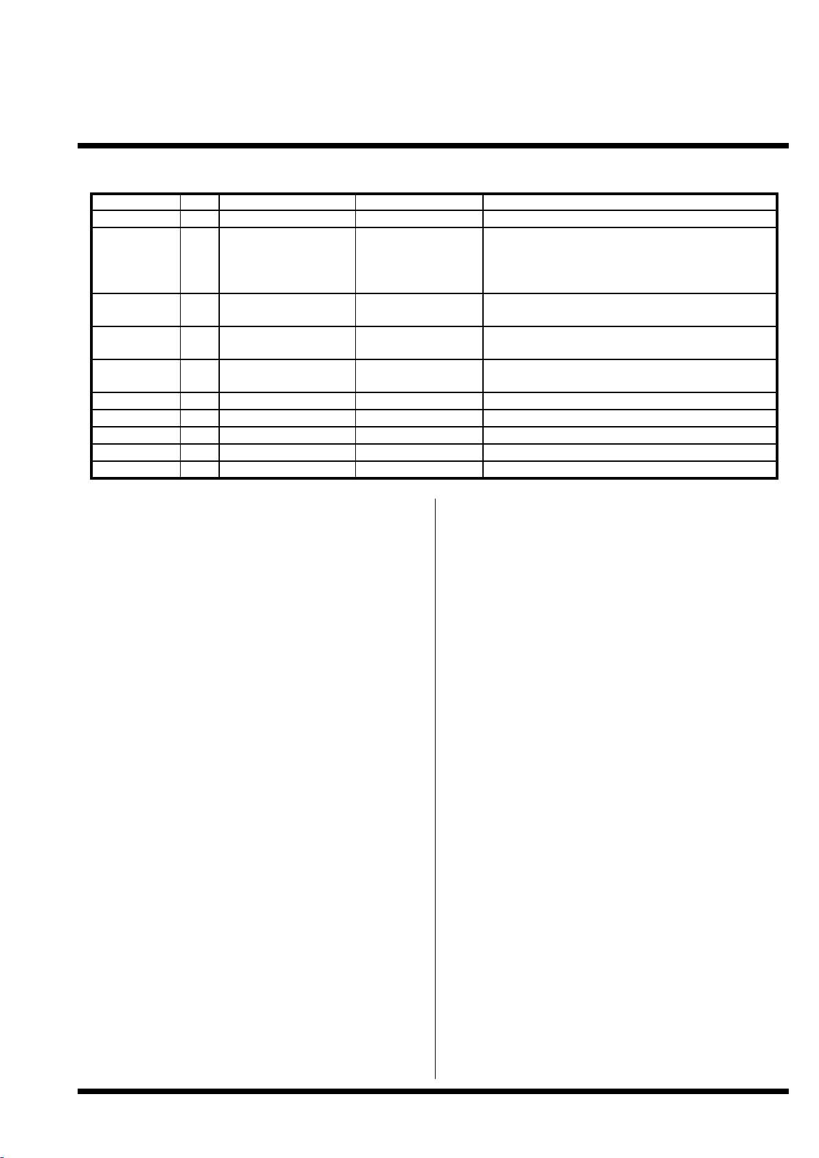
4.2 Pin Descriptions KeyWarrior24-S3
4.3 Pin Functions KeyWarrior24-S3
D+, D-
Differential data lines of USB. Connect these
signals direct to the USB cable or type B plug.
Vreg
Regulated 3V output, to be used only for the
purpose of powering the USB D- pull up resistor.
Do not use this pin as a supply for any other circuit
than the pull up resistor.
A0, B0, A1, B1, A2, B2
Encoder inputs. Up to three incremental encoders
with quadrature signals may be connected here.
Key generation is triggered on the rising edge of A,
the status of B is then used to determine which one
of two codes is generated. The assigned keys are
pressed and released immediately. Macros can be
assigned to encoders.
Internal pull up resistors are activated on device
reset.
Sw[0:8]
Inputs for the nine keys. Switches closing to
ground should be connected here.
Internal pull up resistors are activated on device
reset.
/En
Enable output for the power supply to the
encoders. To meet USB standby power
specifications it is necessary to disable the power
supply to the encoders during USB suspend status.
Power to the encoders must be supplied only when
this pin is low.
Full
Pulling this pin high reduces the encoder resolution
to full pulses, i.e. a key stroke is generated only
after a full encoder step with four edges on the A/B
lines did happen.
Internal weak pull down resistor.
Pull to GND
This pin is used during production of the
KeyWarrior chips, connect to GND.
GND
Power supply ground.
Vcc
Supply voltage.
Name
I/O
Type
Pins
Description
D+, D-
A0, B0, A1,
B1, A2, B2
I/OIspecial
inputs with internal
pull ups
16, 15
1, 2, 3, 4, 24, 23, 22,
21
USB differential data lines
A, B inputs for three encoders
Sw0..Sw8
/En
Full
PullToGND
IOinputs with internal
pull ups
open drain output with
internal pull up
I
input, internal weak
pull down
5, 20, 6, 19, 7, 18, 8,
17
Inputs for the nine direct connected keys. Switches
should close to ground
Enable output to control power to the encoders,
encoders actie when low
1210Pull high to reduce encoder resolution to full pulses
Used during manufacturing, connect to GND
GND
Vcc
Vre gNCPower supply
Power supply
O-Regulated 3V out
914Ground
Supply voltage
1113Power for D- pullup resistor
do not connect
V 1.1.2, December 2nd 2013, for chip revision 1.1.1.4/1.1.1.B and up
Page 5

Code Mercenaries
5
KK
KK
eeeeyyyyWW
WWaaaarrrrrrrriiii
oooorrrr22
22
44
44
5. Device Operation
KeyWarrior24 registers as a standard HID
keyboard and supports boot protocol. It does not
need any special drivers to be installed, standard
system drivers are sufficient.
The country code is 0 for not localized hardware,
which allows to use a single version of the chip for
all international keyboard layouts. Usage codes are
defined for 0 to 164, which include the Power key
and the = sign in the keypad, as well as the
compose keys for Asian languages and several
special keys that may or may not be supported by
individual operating systems.
In addition the media control keys Mute, Play/
Pause, Eject, Fast Forward, Fast Backward,
5.1 Power Up
Every time the supply voltage is applied
KeyWarrior24 executes an internal reset sequence.
All internal pull up resistors are disabled upon
power up and will be activated during the internal
reset sequence.
5.2 Keyboard Scanning
KeyWarrior24 scans the keyboard matrix every
t
scan
by sequentially pulling one of the Y lines low
and then reading the status at the X lines. When the
scan matrix changes status and then remains stable
for t
debounce
KeyWarrior24 decodes the changes
and generates scancodes.
On KeyWarrior24-S3 the nine direct connected
keys are checked every t
scan
and are decoded after
remaining stable for t
debounce
.
5.2.1 Encoder scanning
KeyWarrior24-S3 scans the encoder inputs at the
highest rate possible. The actual rate depends on
several parameters and is not static.
The encoder inputs are not debounced. It is not
recommended to use mechanical encoders without
an external debouncing circuit. Key strokes are
generated immediately upon detecting the rising
edge on the A signal from an encoder when in Full
mode, in quadrant mode a key is generated on
every edge on A or B.
5.3 Key Rollover
KeyWarrior supports true n-key rollover. All keys
in the matrix may be pressed at the same time
without KeyWarrior missing any code. However
due to the phantom key effect it can not be
guaranteed that combinations of many keys are
properly reported (see 5.3.1).
USB has a limitation on how many keys can be
reported at the same time. On USB any six keys
plus all eight modifiers (GUI, Ctrl, Alt, Shift) may
be pressed at the same time. If more than six
ordinary keys are pressed an error state is reported.
So USB has a 6-key plus modifiers rollover.
5.3.1 Phantom Keys
Phantom keys do occur when three or more keys in
a keyboard matrix are pressed in a combination
that leads to the matrix reading like a fourth key
has been pressed.
To avoid phantom keys diodes may be added to the
keys. If diodes are used they have to be put in
series with the key switches. The kathodes have to
be connected to the Y lines and anodes to X lines.
It is highly recommended to place all modifier
keys on a single row or column and put diodes on
all of them.
5.4 Custom Scancode Tables
The standard KeyWarrior24 has a fixed key table
that is factory programmed. For production
volumes it is possible to order KeyWarrior24 with
an individual key layout.
KeyWarrior uses a single table to translate the
matrix coordinates to USB usage codes. This table
is called the "Master Translation Table".
For information on generating the Master
Translation Table please refer to the document
"Creating Custom KeyWarrior Scancode Tables".
5.5 Function Shift Keys
KeyWarrior24 allows the definition of two function
shift keys. If one of these keys is pressed
KeyWarrior uses a second or third translation table
to convert matrix coordinates to USB usage codes.
This allows a small keyboard to generate all
functions of a full sized keyboard.
The function shift key may be on any coordinate in
the matrix, it is assigned by placing a special code
in the corresponding table position.
V 1.1.2, December 2nd 2013, for chip revision 1.1.1.4/1.1.1.B and up
Page 6
Code Mercenaries
6
KK
KK
eeeeyyyyWW
WWaaaarrrrrrrriiii
oooorrrr22
22
44
44
5.6 Macros
KeyWarrior24 supports the KeyWarrior
Commander type macros. Up to 34 macros can be
defined for custom controllers.
Each macro can contain up to 31 key codes and
can work either in a typing mode or stable mode.
For more information on the macros please refer to
the document "Creating Custom KeyWarrior
Scancode Tables".
5.7 Media Control and Application Keys
KeyWarrior24 supports the most commonly used
subset of the USB HID class usage page $0C
(Consumer Controls). These keys are reported via a
second interface that specifies usage $01 for
General Consumer Device.
The following keys are suppoted:
$00B3 Fast forward
$00B4 Rewind
$00B5 Skip to next Ttrack
$00B6 Skip to previous track
$00B7 Stop
$00B8 Eject
$00CD Play/Pause
$00E2 Audio mute
$00E9 Volume increase
$00EA Volume decrease
$018A Launch email reader
$0196 Launch internet browser
Availability of these key functions may vary
depending on the operating system used.
KeyWarrior24-8M and KeyWarrior24-S3 use these
keys in their standard layouts. The functions may
be placed on any key including the rotary encoders
on KW24-S3.
Other consumer control keys can be made
available for custom versions.
V 1.1.2, December 2nd 2013, for chip revision 1.1.1.4/1.1.1.B and up
Page 7

Code Mercenaries
7
KK
KK
eeeeyyyyWW
WWaaaarrrrrrrriiii
oooorrrr22
22
44
44
V 1.1.2, December 2nd 2013, for chip revision 1.1.1.4/1.1.1.B and up
6. Key Tables of the Standard KeyWarrior24 Chips
The standard layouts of the KeyWarrior24 chips are intended to be used as fixed selections set by hard
wiring the corresponding FN key coordinate, not as optional layouts to be selected by an actual FN key.
6.1 KeyWarrior24-8 Table with no FN key pressed
Generic layout with all main keyboard keys
US keyboard layout
X0 X1 X2 X3 X4 X5 X6 X7
Y0
Y1
7&
4$
8*
5%
9(
6^
A
F
B
G
C
H
D
I
E
J
Y2
Y3
Y4
Y5
1!
-_
2@
0)
, <
]}
. >
up
3#
=+
K
P
/?
\|
U
Z
L
Q
M
R
V
space
W
`~
N
S
O
T
X
l-alt
Y
r-alt
Y6
Y7
left
FN1
down
FN2
right
tab
[{
del
; :
caps
' "
esc
l-ctrl
l-shft`~return
Page 8

Code Mercenaries
8
KK
KK
eeeeyyyyWW
WWaaaarrrrrrrriiii
oooorrrr22
22
44
44----
88
88
V 1.1.0, May xxx 2011, for chip revision 1.1.1.4 DRAFT!
6.1.1 KeyWarrior24-8 Table with no FN key pressed / USB Usage Codes
X0 X1 X2 X3 X4 X5 X6 X7
Y0
Y1
$24
$21
$25
$22
$26
$23
$04
$09
$05
$0A
$06
$0B
$07
$0C
$08
$0D
Y2
Y3
Y4
Y5
$1E
$2D
$1F
$27
$36
$30
$37
$52
$20
$2E
$0E
$13
$38
$31
$18
$1D
$0F
$14
$10
$15
$19
$2C
$1A
$35
$11
$16
$12
$17
$1B
$E2
$1C
$E6
Y6
Y7
$50
FN1
$51
FN2
$4F
$2B
$2F
$2A
$33
$39
$34
$29
$E0
$E1
$64
$28
Page 9

Code Mercenaries
9
KK
KK
eeeeyyyyWW
WWaaaarrrrrrrriiii
oooorrrr22
22
44
44----
88
88
V 1.1.0, May xxx 2011, for chip revision 1.1.1.4 DRAFT!
6.1.2 KeyWarrior24-8 Table with FN1 key pressed
Layout for hex, special function, or POS keyboard.
US keyboard layout
X0
X1
X2
X3
X4
X5
X6
X7
Y0
Y1
Y2
Y3
Y4
Y5
Y6
Y7
X0 X1 X2 X3 X4 X5 X6 X7
Y0
Y1
num
num7
num/
num8
num*
num9
num-
num+
A
B
F1
F4
F2
F5
F3
F6
Y2
Y3
Y4
Y5
num4
num1
num5
num2
num0
num=
space
up
num6
num3
Enter
num=
num.
num00Falt-F4
C
D
F7
F10
E
alt-F5
alt-F1
alt-F6
F8
F11
F9
F12
alt-F2
l-alt
alt-F3
r-alt
Y6
Y7
left
FN1
down
FN2
right
tab
alt-F7
del
alt-F8
alt-F11
alt-F9
esc
l-ctrl
l-shft
alt-F10
return
Page 10

Code Mercenaries
10
KK
KK
eeeeyyyyWW
WWaaaarrrrrrrriiii
oooorrrr22
22
44
44----
88
88
V 1.1.0, May xxx 2011, for chip revision 1.1.1.4 DRAFT!
6.1.3 KeyWarrior24-8 Table with FN1 key pressed / USB Usage Codes
X0 X1 X2 X3 X4 X5 X6 X7
Y0
Y1
$53
$5F
$54
$60
$55
$61
$56
$57
$04
$05
$3A
$3D
$3B
$3E
$3C
$3F
Y2
Y3
Y4
Y5
$5C
$59
$5D
$5A
$62
$2E
$2C
$52
$5E
$5B
$58
$86
$63
$62
$62
$09
$E2
$3D
$06
$07
$40
$43
$08
$E2
$3E
$E2
$3A
$E2
$3F
$41
$44
$42
$45
$E2
$3B
$E2
$E2
$3C
$E6
Y6
Y7
$50
FN1
$51
FN2
$4F
$2B
$E2
$40
$2A
$E2
$41
$E2
$44
$E2
$42
$29
$E0
$E1
$E2
$43
$28
Page 11

Code Mercenaries
11
KK
KK
eeeeyyyyWW
WWaaaarrrrrrrriiii
oooorrrr22
22
44
44----
88
88
V 1.1.0, May xxx 2011, for chip revision 1.1.1.4 DRAFT!
6.1.4 KeyWarrior24-8 Table with FN2 key pressed
Special layout for gaming and other applications.
US keyboard layout
X0
X1
X2
X3
X4
X5
X6
X7
Y0
Y1
Y2
Y3
Y4
Y5
Y6
Y7
X0 X1 X2 X3 X4 X5 X6 X7
Y0
Y1
1!
4$
2@
5%
3#
6^
esc
§ ±
num
num7
num/
num8
num*
num9
num-
num+
Y2
Y3
Y4
Y5
7&
0)
8*
tab
Q
A
W
S
9(
del
- _
= +
E
D
R
F
num4
num1
num5
num2
T
G
pause
left
num6
num3
Enter
num.
up
down
num0
right
Y6
Y7
Z
FN1
X
FN2
C
l-shftVl-ctrl
B
l-alt
. >
r-alt
/ ?
r-ctrl
space
r-shft
Page 12

Code Mercenaries
12
KK
KK
eeeeyyyyWW
WWaaaarrrrrrrriiii
oooorrrr22
22
44
44----
88
88
V 1.1.0, May xxx 2011, for chip revision 1.1.1.4 DRAFT!
6.1.5 KeyWarrior24-8 Table with FN2 key pressed / USB Usage Codes
X0 X1 X2 X3 X4 X5 X6 X7
Y0
Y1
$1E
$21
$1F
$22
$20
$23
$29
$35
$53
$5F
$54
$60
$55
$61
$56
$57
Y2
Y3
Y4
Y5
$24
$27
$25
$2B
$14
$04
$1A
$16
$26
$2A
$2D
$2E
$08
$07
$15
$09
$5C
$59
$5D
$5A
$17
$0A
$48
$50
$5E
$5B
$58
$63
$52
$51
$62
$4F
Y6
Y7
$1D
FN1
$1B
FN2
$06
$E1
$19
$E0
$05
$E2
$37
$E6
$38
$E4
$2C
$E5
Page 13

Code Mercenaries
13
KK
KK
eeeeyyyyWW
WWaaaarrrrrrrriiii
oooorrrr22
22
44
44
V 1.1.0, May xxx 2011, for chip revision 1.1.1.4 DRAFT!
6.2 KeyWarrior24-8M Table with no FN key pressed
Media control layout
US keyboard layout
X0 X1 X2 X3 X4 X5 X6 X7
Y0
Y1
eject
rewind
vol +
stop
vol -
start
brwsr.
mute
start
mailer
play/
pause
F1
next
track
F2
prev
track
F3
fast
fwd
F4
Y2
Y3
Y4
Y5
F5
ctrl-XF6ctrl-C
cmd-X
space
cmd-C
up
F7
ctrl-VF8ctrl-Z
cmd-V
ctrl-
alt-del
cmd-Z
Ins
F9
ctrl-A
F10
ctrl-O
cmd-A
home
cmd-O
pg up
F11
ctrl-S
F12
ctrl-S
cmd-S
l-alt
cmd-S
r-alt
Y6
Y7
left
FN1
down
FN2
right
tab
del
bksp
end
l-shft
pg dn
esc
l-ctrl
r-shft
r-ctrl
return
Page 14

Code Mercenaries
14
KK
KK
eeeeyyyyWW
WWaaaarrrrrrrriiii
oooorrrr22
22
44
44----
88
88
V 1.1.0, May xxx 2011, for chip revision 1.1.1.4 DRAFT!
6.2.1 KeyWarrior24-8M Table with no FN key pressed / USB Usage Codes
X0 X1 X2 X3 X4 X5 X6 X7
Y0
Y1
CC
$B8
CC
$B4
CC
$E9
CC
$B7
CC
$EA
CC
$0196
CC
$E2
CC
$18A
CC
$CD
$3A
CC
$B5
$3B
CC
$B6
$3C
CC
$B3
$3D
Y2
Y3
Y4
Y5
$3E
$E0
$1B
$3F
$E0
$06
$E3
$1B
$2C
$E0
$06
$52
$40
$E0
$19
$41
$E0
$09
$E0
$19
$E0
$E2
$4C
$E3
$09
$49
$42
$E0
$04
$43
$E0
$12
$E3
$04
$4A
$E3
$12
$4B
$44
$E0
$16
$45
$E0
$13
$E3
$16
$E2
$E3
$13
$E6
Y6
Y7
$50
FN1
$51
FN2
$4F
$2B
$4C
$2A
$4D
$E1
$4E
$29
$E0
$E5
$E4
$28
Page 15

Code Mercenaries
15
KK
KK
eeeeyyyyWW
WWaaaarrrrrrrriiii
oooorrrr22
22
44
44----
88
88
V 1.1.0, May xxx 2011, for chip revision 1.1.1.4 DRAFT!
6.2.2 KeyWarrior24-8M Table with FN1 key pressed
Layout for general use.
US keyboard layout
X0
X1
X2
X3
X4
X5
X6
X7
Y0
Y1
Y2
Y3
Y4
Y5
Y6
Y7
X0 X1 X2 X3 X4 X5 X6 X7
Y0
Y1
7&
4$
8*
5%
9(
6^
A
F
B
G
C
H
D
I
E
J
Y2
Y3
Y4
Y5
1!
-_
2@
0)
, <
]}
. >
up
3#
=+
K
P
/ ?
\|
U
Z
L
Q
M
R
V
space
W
`~
N
S
O
T
X
l-alt
Y
r-alt
Y6
Y7
left
FN1
down
FN2
right
tab
[{
del
;:
caps
' "
esc
l-ctrl
l-shft`~return
Page 16

Code Mercenaries
16
KK
KK
eeeeyyyyWW
WWaaaarrrrrrrriiii
oooorrrr22
22
44
44----
88
88
V 1.1.0, May xxx 2011, for chip revision 1.1.1.4 DRAFT!
6.2.3 KeyWarrior24-8M Table with FN1 key pressed / USB Usage Codes
X0 X1 X2 X3 X4 X5 X6 X7
Y0
Y1
$24
$21
$25
$22
$26
$23
$04
$09
$05
$0A
$06
$0B
$07
$0C
$08
$0D
Y2
Y3
Y4
Y5
$1E
$2D
$1F
$27
$36
$30
$37
$52
$20
$2E
$0E
$13
$38
$31
$18
$1D
$0F
$14
$10
$15
$19
$2C
$1A
$35
$11
$16
$12
$17
$1B
$E2
$1C
$E6
Y6
Y7
$50
FN1
$51
FN2
$4F
$2B
$2F
$2A
$33
$39
$34
$29
$E0
$E1
$64
$28
Page 17

Code Mercenaries
17
KK
KK
eeeeyyyyWW
WWaaaarrrrrrrriiii
oooorrrr22
22
44
44----
88
88
V 1.1.0, May xxx 2011, for chip revision 1.1.1.4 DRAFT!
6.2.4 KeyWarrior24-8M Table with FN2 key pressed
Special layout for gaming and other applications.
US keyboard layout
X0
X1
X2
X3
X4
X5
X6
X7
Y0
Y1
Y2
Y3
Y4
Y5
Y6
Y7
X0 X1 X2 X3 X4 X5 X6 X7
Y0
Y1
1!
4$
2@
5%
3#
6^
esc
§ ±
num
num7
num/
num8
num*
num9
num-
num+
Y2
Y3
Y4
Y5
7&
0)
8*
tab
Q
A
W
S
9(
del
- _
= +
E
D
R
F
num4
num1
num5
num2
T
G
pause
left
num6
num3
Enter
num.
up
down
num0
right
Y6
Y7
Z
FN1
X
FN2
C
l-shftVl-ctrl
B
l-alt
. >
r-alt
/ ?
r-ctrl
space
r-shft
Page 18

Code Mercenaries
18
KK
KK
eeeeyyyyWW
WWaaaarrrrrrrriiii
oooorrrr22
22
44
44----
88
88
V 1.1.0, May xxx 2011, for chip revision 1.1.1.4 DRAFT!
6.2.5 KeyWarrior24-8M Table with FN2 key pressed / USB Usage Codes
X0 X1 X2 X3 X4 X5 X6 X7
Y0
Y1
$1E
$21
$1F
$22
$20
$23
$29
$35
$53
$5F
$54
$60
$55
$61
$56
$57
Y2
Y3
Y4
Y5
$24
$27
$25
$2B
$14
$04
$1A
$16
$26
$2A
$2D
$2E
$08
$07
$15
$09
$5C
$59
$5D
$5A
$17
$0A
$48
$50
$5E
$5B
$58
$63
$52
$51
$62
$4F
Y6
Y7
$1D
FN1
$1B
FN2
$06
$E1
$19
$E0
$05
$E2
$37
$E6
$38
$E4
$2C
$E5
Page 19

Code Mercenaries
19
KK
KK
eeeeyyyyWW
WWaaaarrrrrrrriiii
oooorrrr22
22
44
44----
88
88
V 1.1.0, May xxx 2011, for chip revision 1.1.1.4 DRAFT!
6.3 KeyWarrior24-S3 Table with no FN key pressed
For simplicity of handling KW24S3 uses the same data format for storing the key table as the other
KW24 variants. Though only the first two bytes of each level are used.
The first line that usually holds the keys for the Y0 line does contain the codes for Sw0..7. In the second
line, usually for Y1, the first six bytes contain the codes for the encoders, byte 7 is unused, byte 8 holds
the code for Sw8.
Encoder keys are generated on the rising edge of the A signal. That status of the B signal at that time
determines which of the two codes for the encoder is used, to allow different codes for left/right
movement.
6.3.1 KeyWarrior24-S3 Table with no FN key pressed / USB Usage Codes
Sw0 Sw1 Sw2 Sw3 Sw4 Sw5 Sw6 Sw7
Y0
tab
B0=0
return
B0=1
num-
enter
B1=0
space
B1=1
ins
B2=0
del
B2=1
esc
-
FN1
Sw8
Y1
right
left
down
up
pg up
pg
down
-
FN2
Sw0 Sw1 Sw2 Sw3 Sw4 Sw5 Sw6 Sw7
Y0
$2B
B0=0
$28
B0=1
$58
B1=0
$2C
B1=1
$49
B2=0
$4C
B2=1
$29
-
FN1
Sw8
Y1
$4F
$50
$51
$52
$4E
$4B
-
FN2
Page 20

Code Mercenaries
20
KK
KK
eeeeyyyyWW
WWaaaarrrrrrrriiii
oooorrrr22
22
44
44----
88
88
V 1.1.0, May xxx 2011, for chip revision 1.1.1.4 DRAFT!
6.3.2 KeyWarrior24-S3 Table with FN1 key pressed
6.3.3 KeyWarrior24-S3 Table with FN1 key pressed / USB Usage Codes
Sw0 Sw1 Sw2 Sw3 Sw4 Sw5 Sw6 Sw7
Y0
bksp
B0=0
return
B0=1
num-
enter
B1=0
space
B1=1
ins
B2=0
del
B2=1
esc
-
FN1
Sw8
Y1
tab
shft-
tab
num + num - 1 2 -
FN2
Sw0 Sw1 Sw2 Sw3 Sw4 Sw5 Sw6 Sw7
Y0
$2A
B0=0
$28
B0=1
$58
B1=0
$2C
B1=1
$49
B2=0
$4C
B2=1
$29
-
FN1
Sw8
Y1
$2B
$E1
$2B
$57
$56
$1E
$1F
-
FN2
Page 21

Code Mercenaries
21
KK
KK
eeeeyyyyWW
WWaaaarrrrrrrriiii
oooorrrr22
22
44
44----
88
88
V 1.1.0, May xxx 2011, for chip revision 1.1.1.4 DRAFT!
6.3.4 KeyWarrior24-S3 Table with FN2 key pressed
This layout generates medial control and application control keys
6.3.5 KeyWarrior24-S3 Table with FN2 key pressed / USB Usage Codes
Sw0 Sw1 Sw2 Sw3 Sw4 Sw5 Sw6 Sw7
Y0
eject
B0=0
mute
B0=1
play/
pause
B1=0
stop
B1=1
fast
fwd
B2=0
rewind
B2=1
space-FN1
Sw8
Y1
vol + vol -
next
track
prev
track
fast
fwd
rewind - FN2
Sw0 Sw1 Sw2 Sw3 Sw4 Sw5 Sw6 Sw7
Y0
CC
$B8
B0=0
CC
$E2
B0=1
CC
$CD
B1=0
CC
$B7
B1=1
CC
$B3
B2=0
CC
$B4
B2=1
$2C
-
FN1
Sw8
Y1
CC
$E9
CC
$EA
CC
$B5
CC
$B6
CC
$B3
CC
$B4
- FN2
Page 22

Code Mercenaries
22
KK
KK
eeeeyyyyWW
WWaaaarrrrrrrriiii
oooorrrr22
22
44
44
V 1.1.2, December 2nd 2013, for chip revision 1.1.1.4/1.1.1.B and up
7. DC Characteristics
7.1 AC Characteristics
*) A version with fast scanning to better suit rubber dome keyboards is possible for custom versions.
In this case t
scan
= 1ms, t
debounce
= 2x t
scan
and t
scansu
= 10μs
Parameter Min Max Units Remarks
V
cc
I
cc
Operating Voltage
Operating Supply Current
4.35 5.25
20
V
mA
I
sb
I
ol
I
ol
R
up
Suspend mode current
Max sink current on output pins
Sink current on output pins
Pull-up Resistance 8
25
70
μA
mA
2
24
mA
kΩ
Oscillator off
Cummulative across all ports
Vout = 0.4V
V
ith
V
H
V
oh
Input threshold voltage
Input hysteresis voltage
40%
3%
USB Interface
Static output high 2.8
V
ol
V
di
V
cm
V
se
Static output low
Differential Input sensitivity 0.2
Differential Input common Mode Range
Single Ended Transceiver Threshold
0.8
0.8
60%
10%
V
cc
V
cc
3.6 V
All ports, low to high edge
15kΩ±5% to GND
0.3 V
V
2.5
2.0
V
V
|(D+)-(D-)|
C
in
I
io
R
pu
R
pd
Transceiver capacitance
Hi-Z State Data Line Leakage -10
Bus Pull-up resistance
Bus Pull-down resístance
1.274
14.25
20
10
pF
μA
15.75
15.75
kΩ
kΩ
0V < Vin < 3.3V, Hi-Z State
1.3kΩ±2% to Vreg
15kΩ±5%
Parameter Min Max Units Remarks
clock accuracy
USB Driver Characteristics
-1.5 +1.5 % Derived from USB signal
t
r
t
r
t
f
t
f
Transition rise time
Transition rise time
75
Transition fall time
Transition fall time
75
300
ns
ns
300
ns
ns
CLoad = 200pF
CLoad = 600pF
CLoad = 200pF
CLoad = 600pF
t
rfm
V
crs
t
drate
Rise/Fall Time matching
Output signal crossover voltage
80
1.3
USB Data Timing
Low Speed Data Rate 1.4775
t
djr1
t
djr2
t
deop
t
eopr2
Receiver data jitter tolerance
Receiver data jitter tolerance
-75
-45
Differential to EOP transition skew
EOP width at reeiver
-40
670
125
2.0
%
V
1.5225 MBit/s
75
45
ns
ns
100 ns
ns
To next transition
For paired transitions
Accepts as EOP
t
eopt
t
udj1
t
udj2
Source EOP width
Differential driver jitter
1.25
-95
Differential driver jitter
Keyboard Matrix Scan Timing
-150
t
scan
t
scansu
t
debounce
Scanning interval
Matrix drive to read setup time
4*
typ. 40*
Debounce time
3x t
scan
*
1.50
95
μs
ns
150 ns
To next transition
To paired transition
ms
μs
ms
Page 23

Code Mercenaries
23
KK
KK
eeeeyyyyWW
WWaaaarrrrrrrriiii
oooorrrr22
22
44
44
V 1.1.2, December 2nd 2013, for chip revision 1.1.1.4/1.1.1.B and up
7.2 Absolute Maximum Ratings
Storage Temperature -65°C to +150°C
Ambient Operating Temperature 0°C to +70°C
Supply Voltage on Vcc relative to Vss -0.5V to +7.0V
DC Input Voltage -0.5V + Vcc + 0.5V
Max. Output Current into any Pin 70mA
Power Dissipation 300mW
Static Discharge Voltage >2000V
Latch-up Current >200mA
Page 24

Code Mercenaries
24
KK
KK
eeeeyyyyWW
WWaaaarrrrrrrriiii
oooorrrr22
22
44
44
8. Ordering Information
The standard KeyWarrior24 have a factory
programmed key table which can not be changed
by the user.
Customized KeyWarrior24 chips can be produced
with customer specific key tables if ordered in
production volumes.
For the production of a custom KeyWarrior24 the
customer needs to supply a key table according to
the specs (empty template files are available for
download from our website).
Code Mercenaries will assign a part and version
number to each customer specific chip so it can be
identified for future orders.
Preprogrammed chips are subject to minimum
order quantities and setup charges, please contact
sales for details.
8.1 Shipping info
DIL24 chips come in tubes of 16 each. SOIC24
chips come in tubes of 31 each.
To assure the safest handling we recommed that
you order in multiples of full tubes.
Custom chips can be ordered in full tubes only!
SOIC24 chips are shipped in a moisture barrier bag
when ordered in a minimum quantity of one full
tube.
8.2 USB VendorID and ProductID
By default all KeyWarrior chips are shipped with
the USB VendorID of Code Mercenaries ($7C0 or
decimal 1984).
The ProductID will be assigned by Code
Mercenaries.
On request chips can be equipped with the
customers VendorID and ProductID. VendorIDs
can be obtained from the USB Implementers
Forum <www.usb.org>
The ProductID for the standard KeyWarrior24
chips are:
KeyWarrior24-8 $0220
KeyWarrior24-8M $0221
KeyWarrior24-S3 $0222
ProductIDs are independent of the package type.
Partname Order Code Description Package
KeyWarrior24-8
KeyWarrior24-8
KW24-8-P
KW24-8-S
Fixed layout standard part
Fixed layout standard part
PDIP24
SOIC24
KeyWarrior24-8M
KeyWarrior24-8M
KeyWarrior24-S3
KeyWarrior24-S3
KW24-8M-P
KW24-8M-S
Fixed layout standard part, with media keys
Fixed layout standard part, with media keys
KW24-S3-P
KW24-S3-S
Fixed layout standard part, for rotary encoders
Fixed layout standard part, for rotary encoders
PDIP24
SOIC24
PDIP24
SOIC24
V 1.1.2, December 2nd 2013, for chip revision 1.1.1.4/1.1.1.B and up
Page 25

Code Mercenaries
25
KK
KK
eeeeyyyyWW
WWaaaarrrrrrrriiii
oooorrrr22
22
44
44
V 1.1.2, December 2nd 2013, for chip revision 1.1.1.4/1.1.1.B and up
9 Typical Application for KeyWarrior24-8/KeyWarrior24-8M
R2...7 and T1...3 are only required if lock LEDs are used.
Page 26

Code Mercenaries
26
KK
KK
eeeeyyyyWW
WWaaaarrrrrrrriiii
oooorrrr22
22
44
44
V 1.1.0, May xxx 2011, for chip revision 1.1.1.4 DRAFT!
9.1 Typical Application for KeyWarrior24-S3
Close J1 to set full pulse resolution for encoders
1.1
25.10.2011
KeyWarrior24S3
C1
100nF
1K3
R1
Circuit:C i r c u i t :
Version:V e r si o n :
Date:Da t e :
Drawn
Drawn
by:
by:
Page:
P a g e :
Function:Fun c t i o n :
Rev. Date By Change Sign.
Code Mercenaries
C2
10μF
432
1
USB
+5V
A
B
Vcc
Gnd
En0
En1
En2
T1
BC307
R3
1K
J1
Ke y W arr i o r24 S 3
11
17818
7
16
15
14
13
12
123424
23
22
21
20
6
19
9
10
5
Vcc
Vcc
Gnd
B
A
Gnd
B
A
/EN
Sw8
Vcc
KeyWarrior24S3
NC
B2
Full
A2
B1
A1
VREG
B0
A0
Sw6
Sw5
Sw4
Sw7
D+
D-
D+
D-
GND
+5V
Sw0
Sw1
Sw2
Sw3
VssVpp
Page 27

Code Mercenaries
27
KK
KK
eeeeyyyyWW
WWaaaarrrrrrrriiii
oooorrrr22
22
44
44
10 Package Dimensions
24 Pin DIL
24 Pin SOIC
V 1.1.2, December 2nd 2013, for chip revision 1.1.1.4/1.1.1.B and up
Page 28

Code Mercenaries
28
KK
KK
eeeeyyyyWW
WWaaaarrrrrrrriiii
oooorrrr22
22
44
44
11. ESD Considerations
KeyWarrior has an internal ESD protection to
withstand discharges of more than 2000V without
permanent damage. However ESD may disrupt
normal operation of the chip and cause it to exhibit
erratic behaviour.
For the typical office environment the 2000V
protection is normally sufficient. Though for
industrial use additional measures may be
necessary.
When adding ESD protection to the signals special
care must be taken on the USB signal lines. The
USB has very low tolerance for additional
resistance or capacitance introduced on the USB
differential signals.
11.1 EMC Considerations
KeyWarrior uses relatively low power levels and
so it causes few EMC problems.
To avoid any EMC problems the following rules
should followed:
• Put a 100nF ceramic capacitor right next to the
power supply pins and make sure the PCB
traces between the chips power pins and the
capacitor are as short as possible.
• Run the power supply lines first to the capacitor,
then to the chip.
• Make the matrix lines only as long as absolutely
necessary.
Adding a ferrite bead to the +5V and ground power
supply lines is advisable.
12. Revision History
This is a supplemental data sheet to the
KeyWarrior data sheet. Please refer to the main
data sheet for the revision history.
V1.1.1.4 is the inital release version of the
KeyWarrior24-8.
V1.1.1.B is the initial release version of
KeyWarrior24-8M and KeyWarrior24-S3.
V1.1.1.C added the quadrant mode for KW24-S3.
13. RoHS compatibility
RoHS compatible parts are indicated by a "R"
being appended to the version number.
I.e. a KeyWarrior24-8 in DIL24 package will have
a marking as follows if it is RoHS compatible:
KW24-8-S
V1.1.1.4R
Legal Stuff
This document is ©1999-2013 by Code
Mercenaries Hard- und Software GmbH.
The information contained herein is subject to
change without notice. Code Mercenaries makes
no claims as to the completeness or correctness of
the information contained in this document.
Code Mercenaries assumes no responsibility for
the use of any circuitry other than circuitry
embodied in a Code Mercenaries product. Nor
does it convey or imply any license under patent or
other rights.
Code Mercenaries products may not be used in any
medical apparatus or other technical products that
are critical for the functioning of lifesaving or
supporting systems. We define these systems as
such that in the case of failure may lead to the
death or injury of a person. Incorporation in such a
system requires the explicit written permission of
the president of Code Mercenaries.
Trademarks used in this document are properties of
their respective owners.
Code Mercenaries
Hard- und Software GmbH
Karl-Marx-Str. 147a
12529 Schönefeld
Germany
Tel: +49-3379-20509-20
Fax: +49-33790-20509-30
Mail: support@codemercs.com
Web: www.codemercs.com
HRB 9868 CB
Geschäftsführer: Guido Körber, Christian Lucht
V 1.1.2, December 2nd 2013, for chip revision 1.1.1.4/1.1.1.B and up
 Loading...