

Page 1
Code Mercenaries
1
JJ
JJ
WW
WW
22
22
44
44
FF
FF
11
11
44
44
1. Features
• USB interface (low speed)
• Full USB V1.1/2.0 compliance
• Full USB HID 1.1 compliance
• 3 axis acceleration measurement
• 14 bit resolution for each axis
• ±1g, ±1.5g, ±2g, ±3g, ±4g, ±8g, or ±16g
software selectable range
• Data can be read via joystick input or direct
• 8 buttons/aux inputs
• Uses a state of the art compact MEMS sensor
• Sensor settings can be stored in EEPROM
• Single +5V power supply
• Available as module, kit, and water proof unit
1.1 Variants
JoyWarrior24F14 are available as either a
completely assembled module, a kit containing the
module, cable and enclosure, or as a water proof
unit in a rugged plastic enclosure.
2. Functional overview
JoyWarrior24F14 uses a MEMS solid state 3 axis
acceleration sensor for acceleration or inclination
measurement.
By default the data is reported as joystick data
which allows to use JoyWarrior24F14 with existing
applications and simplifies implementation for
applications where no detailed handling of the
sensor parameters is required.
Full access to the sensor data and settings is
possible via a generic HID interface (similar to IOWarrior).
Range, bandwith, trigger levels, and other
parameters can be set permanently in the sensors
internal EEPROM. This allows to program the
sensor for a specific application and then use the
joystick data for easy access.
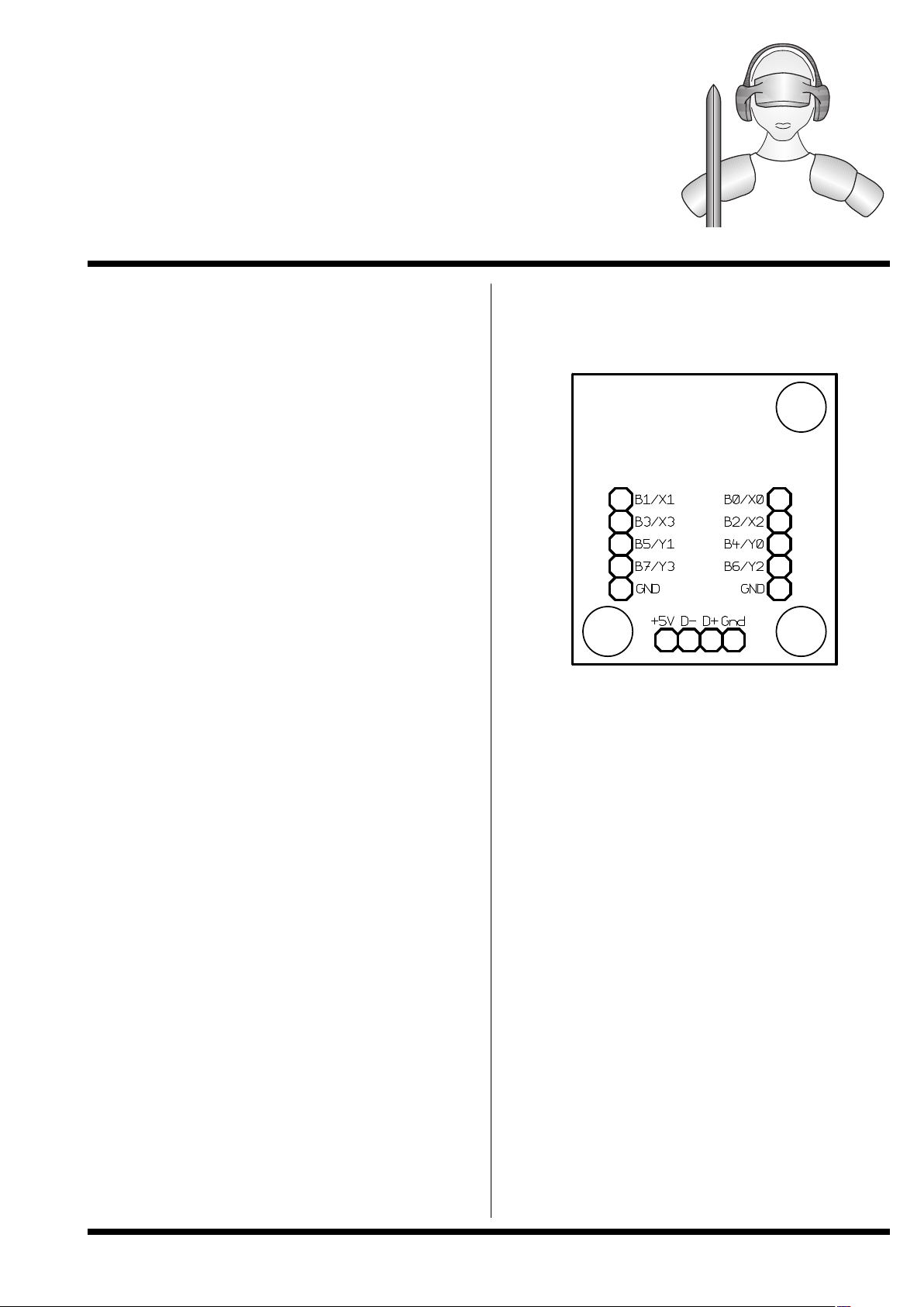
3.0 Pin description JoyWarrior24F14-MOD
D+, D-, Vcc, GND
Connect to a USB cable with a type A plug on its
other end.
B0..B7
Inputs for the buttons or auxiliary inputs. Connect
contacts closing to ground or pull low.
Internal pull up resistors.
V 1.1.2, November 9th 2015 for Chip Revision V1.0.4.0
3D acceleration sensor
Page 2
Code Mercenaries
2
JJ
JJ
WW
WW
22
22
44
44
FF
FF
11
11
44
44
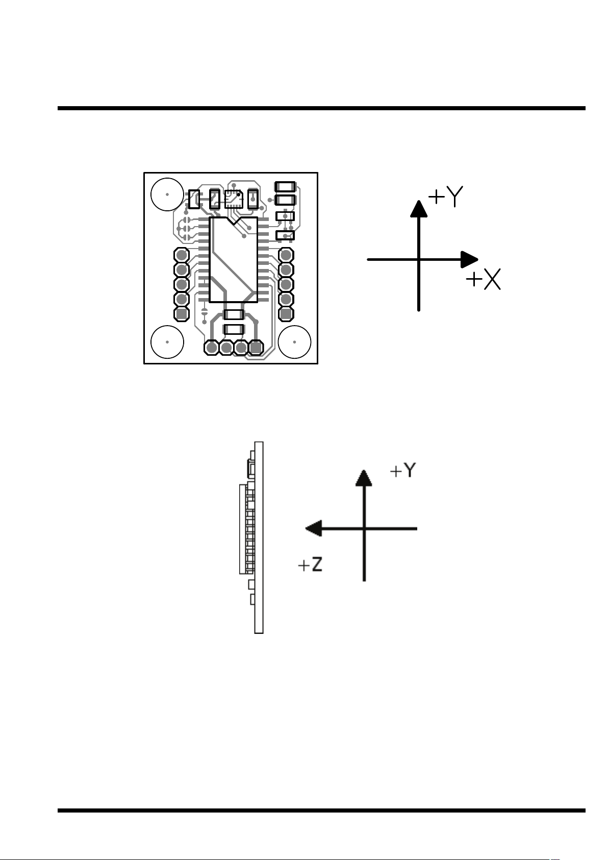
3.2 Axis orientation for JoyWarrior24F14-MOD
V 1.1.2, November 9th 2015 for Chip Revision V1.0.4.0
Page 3
Code Mercenaries
3
JJ
JJ
WW
WW
22
22
44
44
FF
FF
11
11
44
44
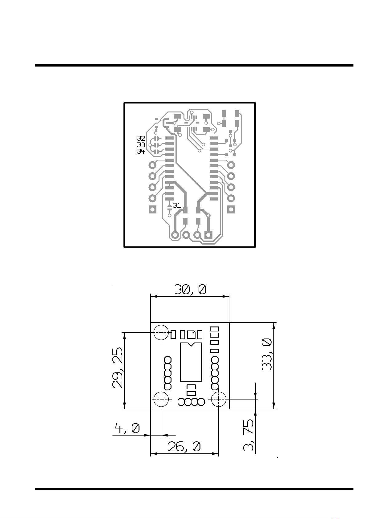
3.3 Jumper positions for JoyWarrior24F14-MOD
3.4 Mechanical dimensions
All dimensions in mm
Mounting holes 2.5mm
V 1.1.2, November 9th 2015 for Chip Revision V1.0.4.0
Page 4
Code Mercenaries
4
JJ
JJ
WW
WW
22
22
44
44
FF
FF
11
11
44
44
3.5 Jumper descriptions:
J1 - RAW, closing this jumper does activate the
RAW mode where unmapped data is reported.
J2, J3, J4 - unused, don't close these jumpers.
V 1.1.2, November 9th 2015 for Chip Revision V1.0.4.0
Page 5
Code Mercenaries
5
JJ
JJ
WW
WW
22
22
44
44
FF
FF
11
11
44
44
4. Device operation
By following the USB HID specifications
JoyWarrior chips are able to work with most
operating systems without the need to supply
special drivers. Any operating system with support
for USB HID devices and game controllers will
have the necessary drivers already in place.
The three axes of the sensor are reported as
joystick axes X, Y, Z with 14 bit resolution.
4.1 Axis orientation
In standard operation the sensor data is mapped to
match the standard behaviour of joystick axes. The
signed 14 bit data from the sensor is changed to
unsigned format with 8191 being the neutral
position (i.e. 0g). The orientation of the sensor Y
axis is inverted. This results in a typical axis
orientation for joysticks when the module is in a
position with the components on top and the sensor
facing away from the user.
By pulling the RAW input high the mapping is
switched off so the sensor data is reported
unprocessed. While this is less useful for joystick
operation it may simplify using the data for
measurement applications.
4.1.1 Data filtering
JoyWarrior24F14 uses an internal median filter to
decimate the raw data stream of the sensor (about
2000 values/s) to the USB report rate (125 reports/
s). This also reduces the noise content of the signal.
4.2 Operation with Windows
Any Windows versions 98 and newer and 2000
and newer will work with JoyWarrior. Older
versions of Windows do not support USB. The
support software is tested with Windows 2000 and
newer.
Upon connecting a JoyWarrior based device for the
first time you may be asked to perform the
standard driver install.
After the driver installation has completed you
should be able to see the device in the "Game
Controllers" control panel and be able to access it
via DirectInput. Also a generic HID device should
show up in the device manager.
Do not use the calibration function of Windows, if
the calibration function is used the data reported by
JoyWarrior24F14 gets modified by Windows. To
get rid of a calibration you have to remove the
JoyWarrior24F14 in the device manager, then
unplug, replug, and reinstall it.
Preferably you should read data in the uncalibrated
format. See the programming examples for details.
4.3 Operation with MacOS
On MacOS X access is available via the
HIDManager. Older MacOS versions are not
tested.
There will be no warnings or dialogs when a
properly functioning JoyWarrior based device is
connected under MacOS X, it will simply start to
work.
4.4 Low level sensor access
Reading the sensor data via the joystick interface is
convenient for most applications. However in some
situations a more detailed control over the sensor
may be required, setting the parameters of the
sensor is also not possible via the joystick
interface.
To directly access all registers of the MEMS
sensor JoyWarrior24F14 does have a second
interface (an interface is a logical device in a USB
device) that identifies as a generic HID class
device. Interface 0 is the joystick function that will
be controlled by a system driver. Interface 1
identifies as a generic HID function and can be
controlled from application level on most operating
systems.
For details of the sensor data please refer to the
Bosch BMA180 data sheet.
When accessing the sensor directly make sure you
have understood the working details of the sensor.
There are a couple registers which must not be
overwritten, otherwise the calibration of the sensor
may be lost permanently.
Data is send to the sensor in a report with the
following format:
Flag/Cnt - Contains a flag to disable the joystick
data polling and a data count:
7 - Disable flag, 1 = disable
6 - unused, zero
5 - unused, zero
4 - unused, zero
3 - unused, zero
2 - data count MSB
1 - data count
0 - data count LSB
Data count may be 0 to 7, denoting the number of
bytes to write to the sensor or read from it.
It is recommended to disable the joystick data
polling while communicating with the sensor. So
the first report before actually starting
communication with the sensor should have a $80
in the first byte and no data.
0
Flag/Cnt
12
Dat0 Dat1
34
Dat2 Dat3
56
Dat4 Dat57Dat6
V 1.1.2, November 9th 2015 for Chip Revision V1.0.4.0
Page 6

Code Mercenaries
6
JJ
JJ
WW
WW
22
22
44
44
FF
FF
11
11
44
44
Since the communication with the sensor works via
SPI the same number of bytes as written to the
sensor is read from it at the same time. The data
read from the sensor is returned in a report with the
following format:
Count is the number of bytes read from the sensor,
it may range from 0 to 7. Since the first byte
written to the sensor is always the register address
the first byte read contains random data.
If a pure write transaction to the sensor is done the
read data report is also returned, it will contain
random data but a correct count.
4.5 Calibration
The sensors are factory calibrated for neutral
position and range. Due to mechanical tolerances
during soldering the MEMS sensor element on the
module and mounting the module in the
application a recalibration of the neutral position
may be necessary.
A calibration tool is provided that allows to
calibrate the neutral position. To do the calibration
the sensor needs to be in a stable horizontal
position, with the components facing upwards.
Start the calibration tool and click on "calibrate",
don't move the sensor while the calibration
proceeds.
JoyWarrior24F14 allows calibration to within ±
5mg of zero.
In addition to the neutral position calibration the
gain can also be calibrated, though the calibration
tool does not support setting the gain values. It is
not recommended to change the gain values unless
the process for this type of calibration is properly
understood. Once overwritten there is no way to
retrieve the original gain settings from the sensor.
Writing the gain values can permanently
decalibrate your sensor.
4.6 Sensor parameters
The sensor programming tool allows to set the
relevant sensor parameters which can be used with
the JoyWarrior24F14.
Primary parameters are the measurement range and
the filter setting.
When using the sensor programming tool you have
the option to write to the working registers or the
EEPROM of the sensor. Settings written to the
EEPROM will be stored permanently and will be
used by the sensor after a power down or reset.
Writing to the working registers should be used to
test settings prior to overwriting the factory
settings in the EEPROM. Factory settings can not
be restored from within the sensor.
It is also possible to store the settings to a file. The
settings file may then either be used by the
programming tool or by the automated
programming tool, which is intended to set
multiple sensors to identical parameters.
To use the automatic programming tool you first
have to create a settings file with the programming
tool. Then start the automatic programming tool
and load the settings file. Any JoyWarrior24F14
that gets connected now will automatically get the
settings written to its sensor EEPROM.
4.7 Measurement range
On JoyWarrior24F14 the resolution is always
14bits and the measurement rage can be ±1g, ±
1.5g, ±2g, ±3g, ±4g, ±8g, or ±16g.
When written to the sensor EEPROM the selected
range will automatically be used every time the
sensor is powered up.
4.8 Bandwidth
The sensor element of JoyWarrior24F14 has an
internal filter to reduce the signal bandwidth. The
filter can be set to work as a low pass with cut off
at 10, 20, 40, 75, 150, 300, 600, or 1200Hz.
Additionally a high pass filter with 1Hz cut off and
a band pass for 0.2Hz to 300Hz are available.
Since the data rate is limited to 125 reports per
second it does not make sense to use low pass filter
settings above 75Hz.
Use of the lowest possible bandwidth for the
chosen application is recommended to reduce the
noise level.
0
Count
12
Dat0 Dat1
34
Dat2 Dat3
56
Dat4 Dat57Dat6
V 1.1.2, November 9th 2015 for Chip Revision V1.0.4.0
Page 7

Code Mercenaries
7
JJ
JJ
WW
WW
22
22
44
44
FF
FF
11
11
44
44
5. DC Characteristics
5.1 AC Characteristics
V 1.1.2, November 9th 2015 for Chip Revision V1.0.4.0
Parameter Min Max Units Remarks
V
cc
I
cc
Operating voltage
Operating supply current
4.35 5.25
20
V
mA
I
sb
I
sb
R
up
V
ith
Suspend mode current (chip)
Suspend mode current (module)
Pull-up resistance
Input threshold voltage
8
40%
25
350
μA
μA
24
60%
kΩ
Vcc
Oscillator off
Sensor working
V
oh
V
ol
V
di
USB Interface
Static output high 2.8
Static output low
Differential input sensitivity 0.2
V
cm
V
se
C
in
I
io
Differential input common mode range
Single ended transceiver threshold
0.8
0.8
Transceiver capacitance
Hi-Z State data line leakage -10
3.6 V
0.3 V
V
15kΩ±5% to GND
|(D+)-(D-)|
2.5
2.0
V
V
20
10
pF
μA 0V < Vin < 3.3V, Hi-Z State
R
pu
R
pd
Bus pull-up resistance
Bus pull-down resistance
1.274
14.25
1.326
15.75
kΩkΩ1.3kΩ±2% to Vreg
15kΩ±5%
Parameter Min Max Units Remarks
F
iclk2
Internal clock frequency
USB Driver Characteristics
5.91 6.09 MHz Clock synchronized to USB
t
r
t
r
t
f
t
f
Transition rise time
Transition rise time
75
Transition fall time
Transition fall time
75
300
ns
ns
300
ns
ns
CLoad = 50pF
CLoad = 350pF
CLoad = 50pF
CLoad = 350pF
t
rfm
V
crs
t
drate
Rise/Fall time matching
Output signal crossover voltage
80
1.3
USB Data Timing
Low speed data rate 1.4775
t
djr1
t
djr2
t
deop
t
eopr1
Receiver data jitter tolerance
Receiver data jitter tolerance
-75
-45
Differential to EOP transition skew
EOP width at receiver
-40
165
125
2.0
%
V
1.5225 MBit/s
75
45
ns
ns
100 ns
ns
To next transition
For paired transitions
Rejects as EOP
t
eopr2
t
eopt
t
udj1
t
udj2
EOP width at receiver
Source EOP width
675
1.25
Differential driver jitter
Differential driver jitter
-95
-150
1.50
ns
μs
95
150
ns
ns
Accepts as EOP
To next transition
To paired transition
Page 8

Code Mercenaries
8
JJ
JJ
WW
WW
22
22
44
44
FF
FF
11
11
44
44
5.2 Absolute maximum ratings
Storage Temperature -50°C to +150°C
Ambient Operating Temperature 0°C to +70°C
Supply Voltage on VCC relative to VSS -0.5V to +7.0V
DC Input Voltage -0.5V to VCC + 0.5V
Max. Output Current into any Pin 60mA
Power Dissipation 300mW
Static Discharge Voltage (USB and button inputs) >2000V
Latch-up Current >200mA
EEPROM write cycles (same byte) ≥1000
EEPROM data retention (at 55°C after 1000 cycles) ≥10 years
Mechanical Shock * 10,000g, ≤100μs
2,000g, ≤1ms
Free fall onto hard surface * ≤1.5m
*) Maximum shock specs apply for the sensor element only. Using the module in high g environments
will require additional mechanical protection.
5.3 Sensor characteristics
Parameter Min Typ Max Units
S
1g
S
1.5g
Acceleration resolution at ±1g
Acceleration resolution at ±1.5g
8192 ±2%
5460 ±2%
LSB/g
LSB/g
S
2g
S
3g
S
4g
S
8g
Acceleration resolution at ±2g
Acceleration resolution at ±3g
Acceleration resolution at ±4g
Acceleration resolution at ±8g
4096 ±1.5%
2730 ±2%
2048 ±2%
1024 ±2.5%
LSB/g
LSB/g
LSB/g
LSB/g
S
16g
TCS
Off
Off
Acceleration resolution at ±16g
Temperature Coefficient of Sensitivity
Zero-g Offset at TA = 25°C
Zero-g Offset over lifetime, TA = 25°C
-15
-35
NL
NL
NL
Zero-g Offset temperature drift
Nonlinearity 1g, 1.5g, 2g -0.10%
Nonlinearity 3g, 4g
Nonlinearity 8g, 16g
-0.25%
-0.75%
512 ±3%
±0.01
15
35
LSB/g
%/K
mg
mg
±0.25
0.10%
0.25%
0.75%
mg/K
%FS
%FS
%FS
n
rms
/S
Output Noise (2g, 10Hz)
Cross Axis Sensitivity, relative between axes
150
0.1
μg*√f (filter bandwidth)
%
V 1.1.2, November 9th 2015 for Chip Revision V1.0.4.0
Page 9

Code Mercenaries
9
JJ
JJ
WW
WW
22
22
44
44
FF
FF
11
11
44
44
6. Ordering information
The units listed here are standard products.
Customized versions are available on request.
6.1 Packaging info
JW24F14-MOD modules come in antistatic boxes
or antistatic bags packaged single or bulk.
QCKIT2 and JW24F14-WP are individually
packaged in blisters
6.2 USB VendorID and ProductID
By default all JoyWarrior controllers are shipped
with the USB VendorID of Code Mercenaries
($7C0 or decimal 1984) and a fixed ProductID.
On request controllers can be equipped with the
customers VendorID and ProductID. VendorIDs
can be obtained from the USB Implementers
Forum <www.usb.org>.
Customized controllers are subject to minimum
order quantities, contact <sales@codemercs.com>
for details.
Following are the ProductIDs for the JoyWarrior
controllers:
JoyWarrior24F8 $1113
JoyWarrior24F14 $1116
ProductIDs are independent of the package type.
See the JoyWarrior data sheet for version
information.
6.3 Serial numbers
The JoyWarrior24F14 has a unique serial number
in its device descriptor. These serial numbers can
be used to simplify programming for multiple
JoyWarriors connected to a single computer.
The serial numbers are factory programmed and
can not be changed. Serial numbers are 8 digit
hexadecimal numbers. No two chips of a type will
be produced with identical serial numbers.
7. Revision history
Please refer to the JoyWarrior main data sheet for
the revision history.
Shipping version of JW24F14 is V1.0.4.0
Legal stuff
This document is ©1999-2015 by Code
Mercenaries GmbH.
The information contained herein is subject to
change without notice. Code Mercenaries makes
no claims as to the completeness or correctness of
the information contained in this document.
Code Mercenaries assumes no responsibility for
the use of any circuitry other than circuitry
embodied in a Code Mercenaries product. Nor
does it convey or imply any license under patent or
other rights.
Code Mercenaries products may not be used in any
medical apparatus or other technical products that
are critical for the functioning of lifesaving or
supporting systems. We define these systems as
such that in the case of failure may lead to the
death or injury of a person. Incorporation in such a
system requires the explicit written permission of
the president of Code Mercenaries.
Trademarks used in this document are properties of
their respective owners.
Code Mercenaries
Hard- und Software GmbH
Karl-Marx-Str. 147a
12529 Schönefeld
Germany
Tel: +49-3379-20509-20
Fax: +49-33790-20509-30
Mail: support@codemercs.com
Web: www.codemercs.com
HRB 9868 CB
Geschäftsführer: Guido Körber, Christian Lucht
V 1.1.2, November 9th 2015 for Chip Revision V1.0.4.0
Partname Order Code Description Package
JoyWarrior24F8 Module
JoyWarrior24F8
discontinued
discontinued
Module
SOIC24
JoyWarrior24F14 Module
QuakeCatcherKit2
JoyWarrior24F14-WP
JW24F14-MOD
QCKIT2
3D acceleration sensor complete module
Kit containing module, cable, enclosure
JW24F14-WP Water proof sensor with 1.8 m USB cable
Module
Kit
water proof
 Loading...