

Code Mercenaries JoyWarrior24 GP 32, JoyWarrior24 A8-8, JoyWarrior24 A8-16, Jo Warrior24A8L, JoyWarrior24A8L User guide
...Page 1
Code Mercenaries
1
JJ
JJ
oo
oo
yy
yy
WW
WW
aa
aarrrrrrrriiii
oo
oorrrr
1.0 Features
• USB interface
• Full USB V1.1/2.0 compliance
• Full USB HID 1.1 compliance
• Available for analog and digital sticks
• Support for up to 8, 16, or 32 buttons
• Compatible with standard system drivers, no
special drivers necessary
• Digital outputs available on some models
• Single +5V power supply
• Available in 24 pin DIL, or 24 pin SOIC
1.1 Variants
JoyWarrior is available in a number of standard
variants. Customized versions are possible.
JoyWarrior24 GP32
• Gamepad style controller, supports four
switches for directions
• Supports up to 32 buttons, arranged in a 8x4
matrix, or up to 12 buttons direct connected
• Minimal external component count (1C, 1R)
JoyWarrior24 A8-8
• Three analog potentiometer axes with 8 bit
resolution each
• Supports up to 8 buttons, direct connected to the
chip
• Autocalibration and autocentering
• Minimal external component count (2C, 1R)
• Low cost yet high quality solution
• Fully assembled modules available
JoyWarrior24 A8-16
• Three analog potentiometer axes with 8 bit
resolution each
• Supports up to 16 buttons, arranged in a 4x4
matrix
• Autocalibration and autocentering
• Minimal external component count (2C, 1R)
• Low cost yet high quality solution
• Fully assembled modules available
JoyWarrior24A8L
• Four analog axes with 8 bit resolution each via
external A/D
• Supports 8 direct connected buttons or 16
buttons in a 4x4 matrix (pin selectable)
• Four auxiliary outputs capable of direct driving
LEDs, supporting flashing modes
JoyWarrior24A10L
• Three analog axes with 10 bit resolution each
via external A/D
• Supports 8 direct connected buttons or 16
buttons in a 4x4 matrix (pin selectable)
• Four auxiliary outputs capable of direct driving
LEDs, supporting flashing modes
JoyWarrior24 RC
• Adapts model RC teacher/student interface as a
USB joystick
• See separate data sheet supplement for details
MouseWarrior24J8
• Mouse/Joystick hybrid low cost controller
• See separate data sheet supplement for details
MouseWarrior24H8
• Mouse/Joystick hybrid controller
• Compatible with hall sensors
• See separate data sheet supplement for details
JoyWarrior24F8/F14
• Three axis acceleration sensor
• See separate data sheet supplement for details
MouseWarrior24F8
• Acceleration sensor based mouse controller
• See separate data sheet supplement for details
1.2 Custom variants
Custom adaptions are available on request.
Special function modifications, like controllers for
pedals, steering wheels etc. are available on
request.
1.3 Obsolete variants
The JoyWarrior20 variants have been discontinued.
To replace the JW20 chips use the following active
products:
JW20GP8 - use JW24GP32
JW20A8-8 - use JW24A8L
JW20A8-16 - use JW24A8L
JW20A10-8 - use JW24A10L
JW20A10-16 - use JW24A10L
For details on the JW20 chips please refer to the
data sheet V1.0.8.
V 1.1.0, July 1st 2010 for Chip Revision V1.0.4.0 and up
Universal joystick and gamepad controller chips
Page 2
Code Mercenaries
2
JJ
JJ
oo
oo
yy
yy
WW
WW
aa
aarrrrrrrriiii
oo
oorrrr
2.0 Functional overview
The JoyWarrior family of joystick controllers
allows to build USB compatible input devices
without the need to acquire USB know how.
Mostly only electro-mechanical components need
to be added to the JoyWarrior chips.
With the wide variety of controller versions most
industrial and game control devices can be built
very easily.
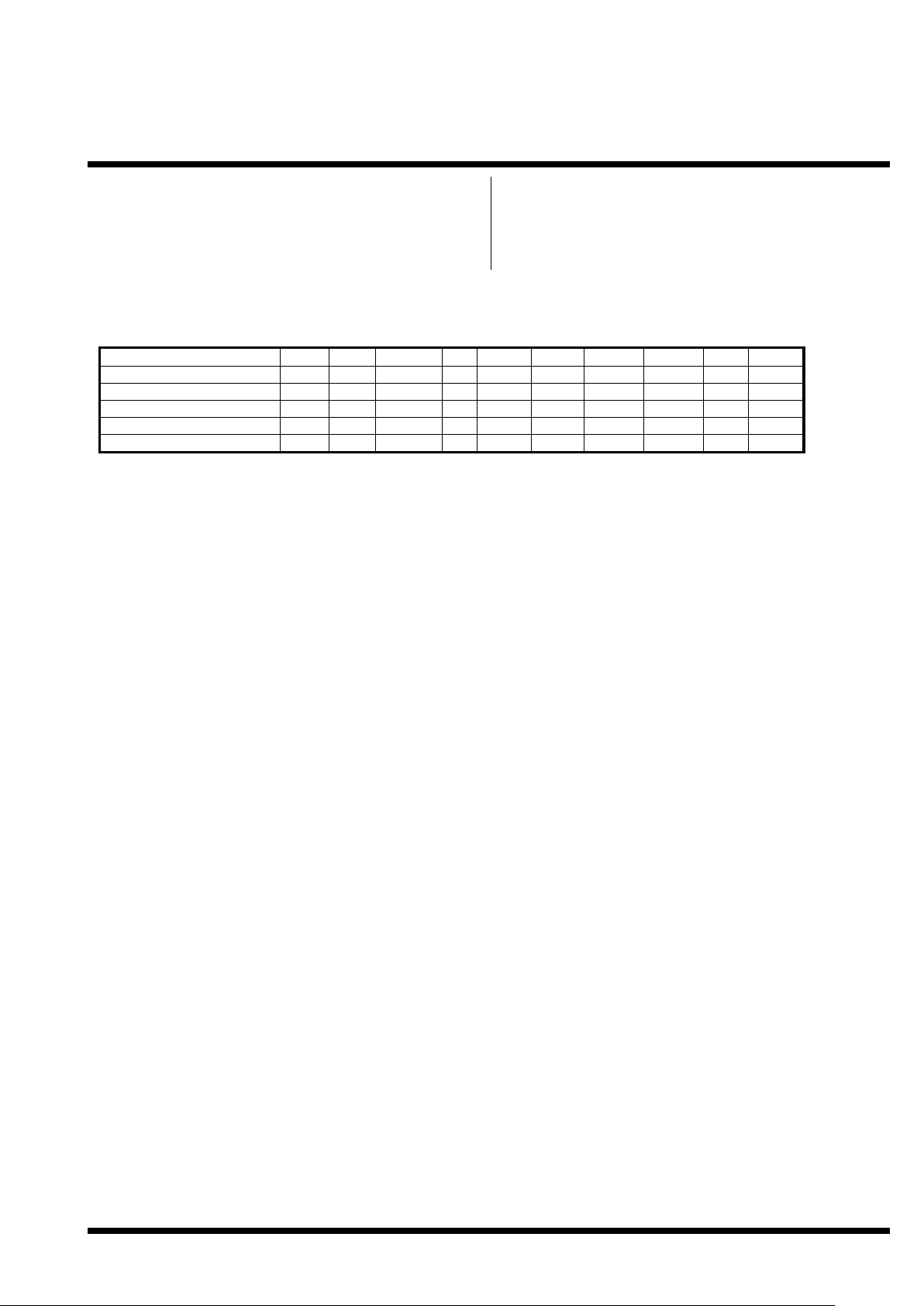
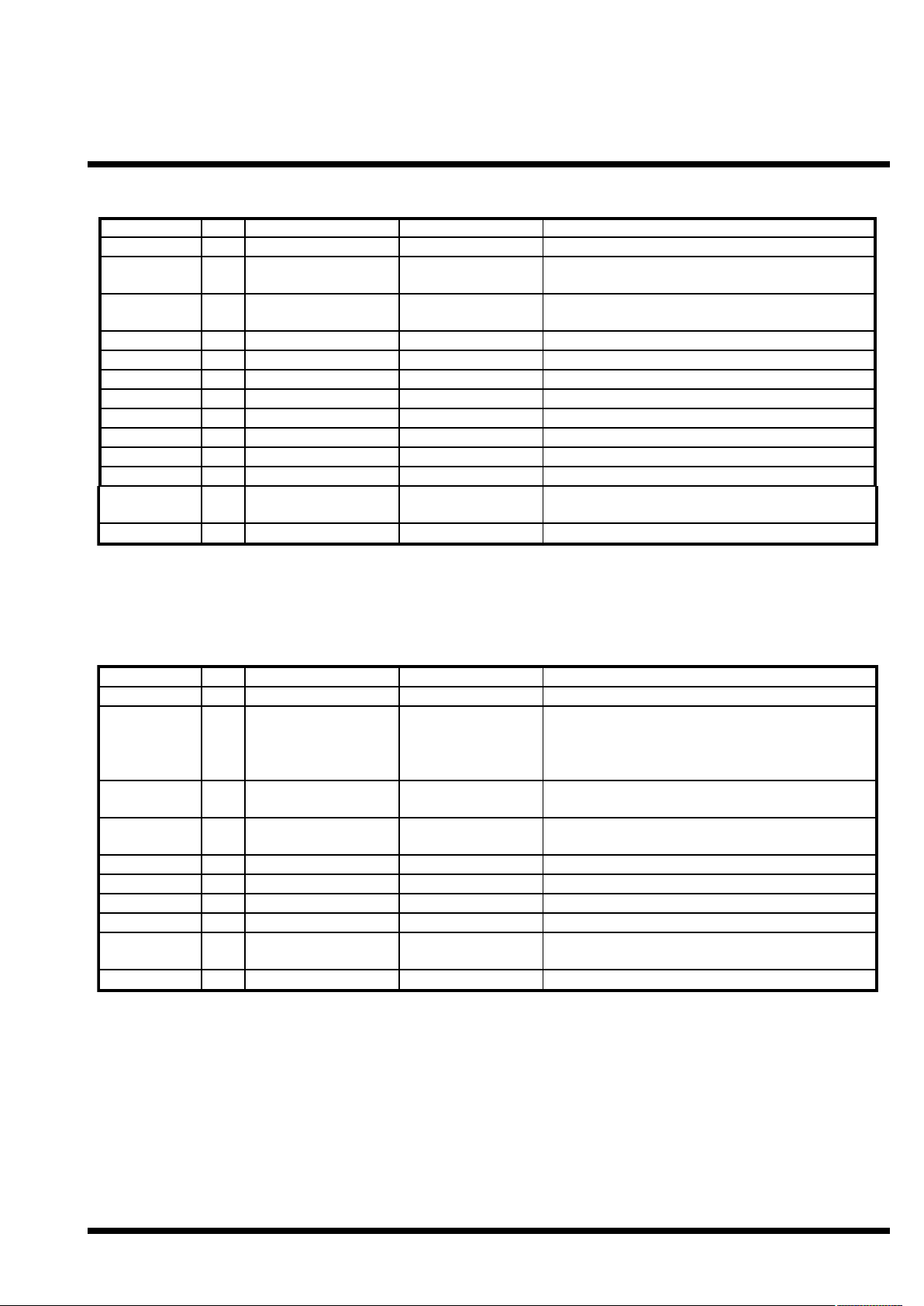
2.1 Product selection matrix
Typ e
JoyWarrior 24 GP32
JoyWarrior 24 A8-8
Analog Digital
-
√
√
JoyWarrior 24 A8-16
JoyWarrior 24 A8L
JoyWarrior 24 A10L
√
√
-
-
√ -
A/D Axes
-
internal-3
Bit/Axis Buttons
n.a.
8
32
8
internal
MAX111334
MAX1249 3
8
8168 or 16
10 8 or 16
Matrix Outputs
8x4 or 12--
-
DIL24 SOIC24
√
√
√
√
4x4
4x4 or 8
-
4
4x4 or 8 4
√
√
√
√
√√
V 1.1.0, July 1st 2010 for Chip Revision V1.0.4.0 and up
Page 3
Code Mercenaries
3
JJ
JJ
oo
oo
yy
yy
WW
WW
aa
aarrrrrrrriiii
oo
oorrrr
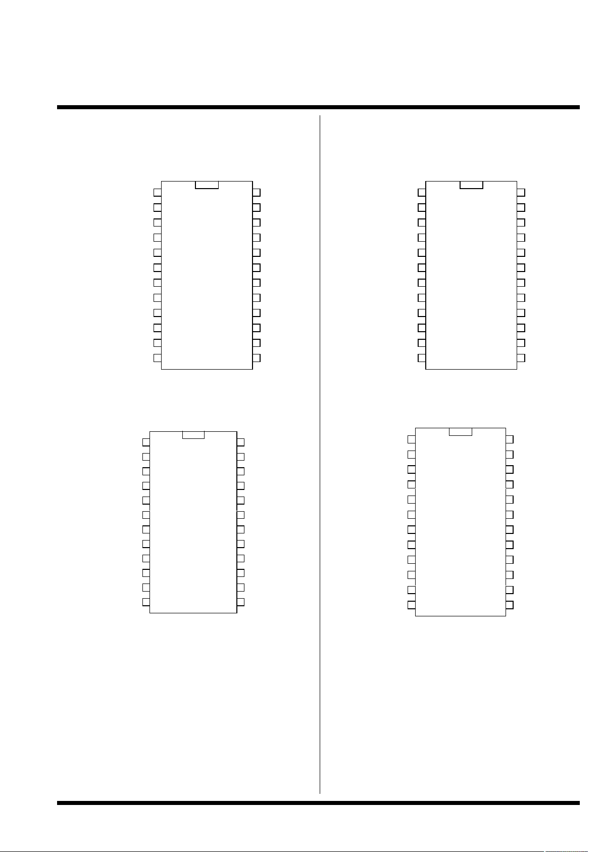
3.0 Pin Configurations (TOP VIEW!)
JoyWarrior24A8-8
24 Pin PDIP or 24 Pin SOIC
JoyWarrior24 GP32-P/S
24 Pin DIL or 24 Pin SOIC
JoyWarrior24A8-16
24 Pin PDIP or 24 Pin SOIC
JoyWarrior24A8L-P/S
JoyWarrior24A10L-P/S
24 Pin DIL or 24 Pin SOIC
1
2
3
4
5
6
7
8
9
10
11
12 13
14
15
16
17
18
19
20
AAAA00
00
AAAA11
11
XXXXRRRR11
11
ZZZZRRRR11
11
XXXXRRRR22
22
BBBB00
00
BBBB44
44
BBBB11
11
BBBB22
22
BBBB33
33
GGGGNN
NNDDDD
DDDD++
++
PPPPuuuullllllllTTTTooooGGGGNNNNDD
DD
DDDD--
--
VVVVRRRREEEEGG
GG
VVVVcccccc
cc
RRRRAAAAWW
WW
NNNNC
C
CC
YYYYRRRR22
22
YYYYRRRR11
11
21
22
23
24
BBBB66
66
BBBB77
77
ZZZZRRRR22
22
BBBB55
55
1
2
3
4
5
6
7
8
9
10
11
12 13
14
15
16
17
18
19
20
XXXX0000////BBBB00
00
XXXX1111////BBBB11
11
XXXX2222////BBBB22
22
XXXX6666////BBBB66
66
XXXX3333////BBBB33
33
RRRRiiiigggghhhhtt
tt
YYYY0000////BBBB88
88
LLLLeeeefffftt
tt
DDDDoooowwwwnn
nn
UUUUpp
pp
GGGGNNNNDD
DD
DDDD++
++
PPPPuuuullllllllTTTTooooGGGGNNNNDD
DD
DDDD--
--
VVVVrrrreeeegg
gg
VVVVcccccc
cc
DDDDiiiirrrreeeecccctt
tt
NNNNCC
CC
XXXX5555////BBBB55
55
XXXX4444////BBBB44
44
21
22
23
24
YYYY2222////BBBB111100
00
YYYY3333////BBBB111111
11
XXXX7777////BBBB77
77
YYYY1111////BBBB99
99
1
2
3
4
5
6
7
8
9
10
11
12 13
14
15
16
17
18
19
20
AAAA00
00
AAAA11
11
XXXXRRRR11
11
ZZZZRRRR11
11
XXXXRRRR22
22
XXXX00
00
YYYY00
00
XXXX11
11
XXXX22
22
XXXX33
33
GGGGNN
NNDDDD
DDDD++
++
PPPPuuuullllllllTTTTooooGGGGNNNNDD
DD
DDDD--
--
VVVVRRRREEEEGG
GG
VVVVcccccc
cc
RRRRAAAAWW
WW
NNNNC
C
CC
YYYYRRRR22
22
YYYYRRRR11
11
21
22
23
24
YYYY22
22
YYYY33
33
ZZZZRRRR22
22
YYYY11
11
1
2
3
4
5
6
7
8
9
10
11
12 13
14
15
16
17
18
19
20
XXXX0000////BBBB00
00
XXXX1111////BBBB11
11
XXXX2222////BBBB22
22
YYYY2222////BBBB66
66
XXXX3333////BBBB33
33
////CCCCSS
SS
AAAAuuuuxxxx00
00
SSSSCCCCLLLLKK
KK
DDDDiiiinn
nn
DDDDoooouuuutt
tt
GGGGNNNNDD
DD
DDDD++
++
PPPPuu
uu
llllllllTTTTooooGGGGNNNNDD
DD
DDDD--
--
VVVVRRRREEEEGG
GG
VVVVcccccc
cc
DDDDiiiirrrreeeecccctt
tt
NNNNCC
CC
YYYY11
11
////BBBB55
55
YYYY0000////BBBB44
44
21
22
23
24
AAAAuuuuxxxx22
22
AAAAuuuuxxxx33
33
YYYY3333////BBBB77
77
AAAAuuuuxxxx11
11
V 1.1.0, July 1st 2010 for Chip Revision V1.0.4.0 and up
Page 4
Code Mercenaries
4
JJ
JJ
oo
oo
yy
yy
WW
WW
aa
aarrrrrrrriiii
oo
oorrrr
4.0 Pin Descriptions JoyWarrior24 GP 32
* See application circuit for external circuitry.
4.1 Pin Descriptions JoyWarrior24 A 8-8
* See application circuit for external circuitry.
Name
I/O
Type
Pins
Description
D+, D-
X0/B0, X1/B1,
X2/B2, X3/B3,
X4/B4, X5/B5,
X6/B6, X7/B7
I/OIspecial
input, internal pull up
16,15
1, 2, 3, 4, 24, 23, 22,
21
USB differential data lines
Button row inputs, active low for matrix mode,
direct button inputs 0..7 for direct connection, active
low
Y0/B8, Y1/B9,
Y2/B10, Y3/
B11
Right
Left
Down
I or O
I
output, open drain, or
input, internal pull up
input, internal pull up
IIinput, internal pull up
input, internal pull up
7, 18, 8, 17
5
Button column outputs, periodically pulled low for
matrix mode, direct button inputs 8..11 for direction
connection mode, active low
Input for right direction switch, active low
206Input for left direction switch, active low
Input for down direction switch, active low
Up
VREG
PullToGND
GND
IOinput, internal pull up
special *
I
power supply
Vcc
Direct
NCIpower supply
input, internal pull
down
unused
1911Input for up direction switch, active low
Power for USB D- pull up resistor
109Used during manufacturing, connect to GND
Ground
1412Supply voltage
Pull high to enable 12 direct connected buttons
instead of 4x8 matrix
13
Do not connect
Name
I/O
Type
Pins
Description
D+, D-
B0, B1, B2,
B3, B4, B5.
B6, B7
I/OIspecial
input, internal pull up
16,15
5, 20, 6, 19, 7, 18, 8,
17
USB differential data lines
Button inputs, active low
A0, A1
XR1, XR2
YR1, YR2
ZR1, ZR2
I/OOspecial *
special *
OOspecial *
special *
1, 2
3, 4
Connect center taps of pots here
Connections for X pot
24, 23
22, 21
Connections for Y pot
Connections for Z pot
VREG
PullToGND
GND
VccOI
special *
power supply
power supply
RAW
NC
I
input, internal pull
down
unused
11
10
Power for USB D- pull up resistor
Used during manufacturing, connect to GND
914Ground
Supply voltage
1213Pull to Vcc to disable auto calibration and centering
Do not connect
V 1.1.0, July 1st 2010 for Chip Revision V1.0.4.0 and up
Page 5
Code Mercenaries
5
JJ
JJ
oo
oo
yy
yy
WW
WW
aa
aarrrrrrrriiii
oo
oorrrr
4.2 Pin Descriptions JoyWarrior24 A 8-16
* See application circuit for external circuitry.
4.3 Pin Descriptions JoyWarrior24A8L and JoyWarrior24A10L
* See application circuit for external circuitry.
Name
I/O
Type
Pins
Description
D+, D-
X0, X1, X2,
X3
I/OIspecial
input, internal pull up
16,15
5, 20, 6, 19
USB differential data lines
Button row inputs, active low
Y0, Y1, Y2,
Y3
A0, A1
XR1, XR2
YR1, YR2
O
I/O
output, open drain,
internal pull up
special *
OOspecial *
special *
7, 18, 8, 17
1, 2
Button column outputs, periodically pulled low
Connect center taps of pots here
3, 4
24, 23
Connections for X pot
Connections for Y pot
ZR1, ZR2
VREG
PullToGND
GND
OOspecial *
special *
I
power supply
Vcc
RAW
NCIpower supply
input, internal pull
down
unused
22, 21
11
Connections for Z pot
Power for USB D- pull up resistor
109Used during manufacturing, connect to GND
Ground
1412Supply voltage
Pull to Vcc to disable auto calibration and centering
13
Do not connect
Name
I/O
Type
Pins
Description
D+, D-
X0/B0, X1/B1,
X2/B2, X3/B3,
Y0/B4, Y1/B5.
Y2/B6, Y3/B7
I/O
I or O
special
input or output, internal
pull up
16,15
1, 2, 3, 4, 24, 23, 22,
21
USB differential data lines
Button inputs, active low for direct connection
mode, row and column lines for matrix mode
/CS, Din,
Dout, SCLK
Aux0, Aux1,
Aux2, Aux3
VREG
PullToGND
I/OOinput or output
output, high and low
drive
O
I
special *
5, 6, 19, 20
7, 18, 8, 17
Connect to external A/D converter
Auxiliary outputs, capable of sinking up to 50mA
(70ma total for all combined)
11
10
Power for USB D- pull up resistor
Used during manufacturing, connect to GND
GND
Vcc
Direct
NC
power supply
power supply
I
input, internal pull
down
unused
914Ground
Supply voltage
1213Pull to Vcc to enable direct connected buttons
Do not connect
V 1.1.0, July 1st 2010 for Chip Revision V1.0.4.0 and up
Page 6
Code Mercenaries
6
JJ
JJ
oo
oo
yy
yy
WW
WW
aa
aarrrrrrrriiii
oo
oorrrr
4.4 Pin descriptions
D+, D-
Differential data lines of USB. Connect these
signals direct to a USB cable. D- requires a pull up
resistor connecting to VREG, see application
circuits for details.
VREG
Supplies 3.3V for the USB D- pull up resistor.
Don't use this pin to supply power to external
circuitry, it does only supply sufficient current for
the pull up resistor.
B0..B7 (JoyWarrior24A8-8)
Inputs for the buttons. Connect contacts closing to
ground.
Internal pull up resistors.
X0/B0..X3/B3 or X0/B0..X7/B7
Matrix row inputs for the buttons. In direct mode
these pins work as direct button inputs, active low,
use contacts closing to ground.
Internal pull up resistors.
Y0/B4..Y3/B7 or Y0/B8..Y3/B11
Matrix column outputs or button inputs for direct
mode. In matrix mode these pins are periodically
pulled low to determine the status of the buttons.
In matrix mode all buttons must be decoupled with
diodes, see application circuit for details.
In direct mode these pins act as active low inputs,
connect contacts closing to ground.
Open drain outputs or inputs with internal pull up
resistor.
Left, Right, Up, Down (JoyWarrior24GP32)
Inputs for the direction pad. Connect contacts
closing to ground.
Internal pull up resistors.
/CS, SCLK, Din, Dout (JoyWarrior24A8L/
A10L)
Signals to connect to the external A/D converter.
JoyWarrior 24A10L requires an external Maxim
MAX1249 A/D converter, JoyWarrior24A8L
requires a Maxim MAX1113.
Internal pull up resistors.
/Pull to GND
This pin is used during production of the
JoyWarrior chips, connect to GND.
A0, A1 (JoyWarrior24A8-x)
The center taps of the pots and a capacitor are
connected to these two pins. The pins are used to
charge the capacitor and measure the time it takes
to discharge the capacitor via the pots.
See application circuits for details.
XR1, XR2, YR1, YR2, ZR1, ZR2
(JoyWarrior24A8-x)
These outputs connect to the outer taps of the pots.
One of them is pulled low at a time to measure
how long it takes to discharge the capacitor via the
pot.
Axis values get smaller when the pot center tap
gets closer to the tap connected to the nR1 pin, i.e.
resistance between nR1 and A0, A1 gets smaller.
RAW (JoyWarrior24A8-x)
Pulling this pin to Vcc disables the autocalibration
and autocentering function. The chip will then
report the raw axis data. This can be useful during
design test or for applications that can't accept the
autocalibration or autocentering feature.
Internal weak pull down resistor.
Direct (all except JoyWarrior24A8-x)
Pulling this pin high disables the matrix scanning
for the buttons and instead uses all button pins as
as direct button inputs for up to 8 or 12
(JW24GP32) buttons pulling to GND.
All button input pins have internal pull ups.
Aux0..Aux3 (JoyWarrior24A8L/A10L)
Auxiliary outputs, active low. Each pin is capable
to sink up to 50mA (70mA combined for all pins).
Push-Pull outputs.
GND
Power supply ground.
Vcc
Supply voltage.
V 1.1.0, July 1st 2010 for Chip Revision V1.0.4.0 and up
Page 7

Code Mercenaries
7
JJ
JJ
oo
oo
yy
yy
WW
WW
aa
aarrrrrrrriiii
oo
oorrrr
5.0 Device Operation
By following the USB HID specifications
JoyWarrior chips are able to work with most
operating systems without the need to supply
special drivers. Any operating system with support
for USB HID game controllers will have the
necessary drivers already in place.
5.1 Operation with Windows
Any Windows versions newer than 98 will work
with JoyWarrior. Older versions of Windows do
not support USB or support only a subset of the
functionality.
Upon connecting a JoyWarrior based device for the
first time you may be asked to perform the
standard driver install. The same may happen if
you connect the device to a different USB port on
the same computer. In this case let the system
install the default drivers.
After the driver installation has completed you
should be able to see the device in the "Game
Controllers" control panel and be able to access it
via DirectInput.
5.2 Operation with MacOS
MacOS 9.0 and up and MacOS X do support
JoyWarrior. Some versions of MacOS 8.x do
support USB as well, though their use is not
recommended.
On MacOS X access to the joystick data is
available via the HIDManager.
There will be no warnings or dialogs when a
properly functioning JoyWarrior based device is
connected under MacOS, it will simply start to
work.
5.3 Protocol Specifics: JoyWarrior24GP32
Even though JoyWarrior24GP32 is a gamepad
style device it does report the directional data as a
joystick with two axes of 8 bit each. For left and up
directions 0 is reported, for neutral 127 and for
right and down 255.
This method was chosen since the gamepad data
format does cause problems with several older OS
variants (Mac and PC) and some games.
5.4 Jitter Filter in JoyWarrior24A8-x
Since any A/D converter generates quantisation
noise (the least significant bit jittering at voltages
close to the threshold between two values)
JoyWarrior24A8-x variants (not JW24A8L) use a
simple but efficient jitter filter. Only if the axis
values change more than ±1 digit the data is
actually send to the host. This efficiently
eliminates quantisation noise but retains full
resolution and reaction speed. If there is still noise
on the axis data you should check your circuit for
the cause.
If the RAW pin on the JoyWarrior24A8-x is pulled
high this will also disable the jitter filter.
5.5 Autocalibration and autocentering JoyWarrior24A8-x
The JoyWarrior24A8-x chips do have a
autocentering and autocalibration function that
compensates mechanical tolerances of the joystick.
When autocalibration and autocentering is
activated (i.e. RAW pin is unconnected or pulled to
Gnd) upon power up the JoyWarrior24A8-x will
sample axis data for about 200msec and then use
the current stick position as center. The chip then
assumes that each pot will reach 60% of its total
range and will scale all axis data accordingly to
cover the value range of 0 to 255. If any axis is
moved beyond the assumed range the scaling will
be adjusted.
To calibrate a joystick with the autocentering
feature activated it is sufficient to place the stick to
about center before plugging it in and then move
the stick to all maximum positions. The
JoyWarrior24A8-x will optimize the value scaling
for best resolution.
Pulling the RAW pin high for more than 20msec
and then let it go low again triggers a recalibration.
5.6 Pot and capacitor values for JW24A8-x
The JoyWarrior24A8 is optimized to be used with
a 4.7nF capacitor and 100kΩ pots. A ceramic multi
layer capacitor may be used as the measuring
capacity. It is not recommended to use ceramic
disk type capacitors because of their microphone
effect.
Varying the pot or capacitor values may result in
sub optimal performance. Larger capacitors may
not sufficiently charge or discharge, while smaller
values may introduce more noise.
To optimize the setup it is recommended to check
out the axis values in RAW mode. Ideally the
values in raw mode should range from 0 at one end
of the pot position to 255 at the other end.
5.7 Remote Wakeup
All JoyWarrior chips support the remote wakeup
feature. They are able to wake the host computer
from sleep state if the host operating system does
enable this feature.
Remote wakeup is initiated by JoyWarrior if any
button is pressed or if any switch of the direction
pad closes. Changes on the analog axes are not detected.
V 1.1.0, July 1st 2010 for Chip Revision V1.0.4.0 and up
Page 8

Code Mercenaries
8
JJ
JJ
oo
oo
yy
yy
WW
WW
aa
aarrrrrrrriiii
oo
oorrrr
5.8 Joystick axis orientation
USB specifies the axis orientation as follows:
For the X axis values should increase for left to
right movement, Y axis values increase for far to
near movements (i.e. pulling the stick gets you
larger values), Z axis values should increase for
high to low movement.
5.9 Non Joystick Applications
USB does allow a Human Interface Device
controller to very detailed specify the function of
axes and buttons. This gives a game controller
device the option to specify a certain axis to be a
throttle or break or something else.
The standard JoyWarrior chips are for general use,
so the analog axes variants just specify X, Y, Z and
the switch inputs are defined as being just buttons.
We can modify the controllers to define axes as
other inputs, like gas or rudder pedals or support
hat switches etc.
However not all available usages are supported by
all operating systems and programs. Windows for
instance supports only a small subset of the
simulation controls page.
If you have special requirements, please contact us
about modifications.
5.10 Auxiliary outputs on JW24A8L/A10L
The JoyWarrior24A8L and JoyWarrior24A10L
chips have four auxiliary outputs that may be used
to drive LED indicators or for other applications.
Due to the significant current sinking cabability of
the outputs they are defined as being active low.
Setting the outputs is done by sending a four byte
Feature report to the joystick device. In most cases
this can be done via standard file I/O functions.
The outputs are set by one byte each, the first byte
sets Aux0, second Aux1 etc.
The bits in the bytes do have the following
meaning:
7 - reserved, write 0
6 - reserved, write 0
5 - reserved, write 0
4 - reserved, write 0
3 - Invert blink mode
2 - reserved, write 0
1 - Mode MSB
0 - Mode LSB
The mode bits determine the behaviour of the
output. Following are the combinations (MSB/
LSB):
00 - Output idle (high)
01 - Output static on (low)
02 - Fast blink mode (1/8th second on/off)
03 - Heart beat blink mode
Heart beat mode switches the output low for 1/16th
second, then high for 1/16th, again low for 1/16th
and then idles high for 13/16th seconds.
The invert bit reverts the ouput status for the blink
modes (no effect on static on/off), this allows to
have two indicators blink in an exactly alternating
pattern.
The output status and blinking is maintained by the
JoyWarrior withoput further host interaction until a
new configuration is send. All outputs go to idle
when the JoyWarrior enters suspend mode.
V 1.1.0, July 1st 2010 for Chip Revision V1.0.4.0 and up
Page 9

Code Mercenaries
9
JJ
JJ
oo
oo
yy
yy
WW
WW
aa
aarrrrrrrriiii
oo
oorrrr
6.0 Absolute Maximum Ratings
Storage Temperature ........................................................................................-65°C to +150°C
Ambient Temperature with power applied...........................................................-0°C to +70°C
Supply voltage on Vcc relative to Gnd ..................................................................-0.5V to +7V
DC input voltage...........................................................................................-0.5V to Vcc+0.5V
Maximum current into all ports.........................................................................................70mA
Power Dissipation...........................................................................................................300mW
Static discharge voltage..................................................................................................>2000V
Latch-up current............................................................................................................>200mA
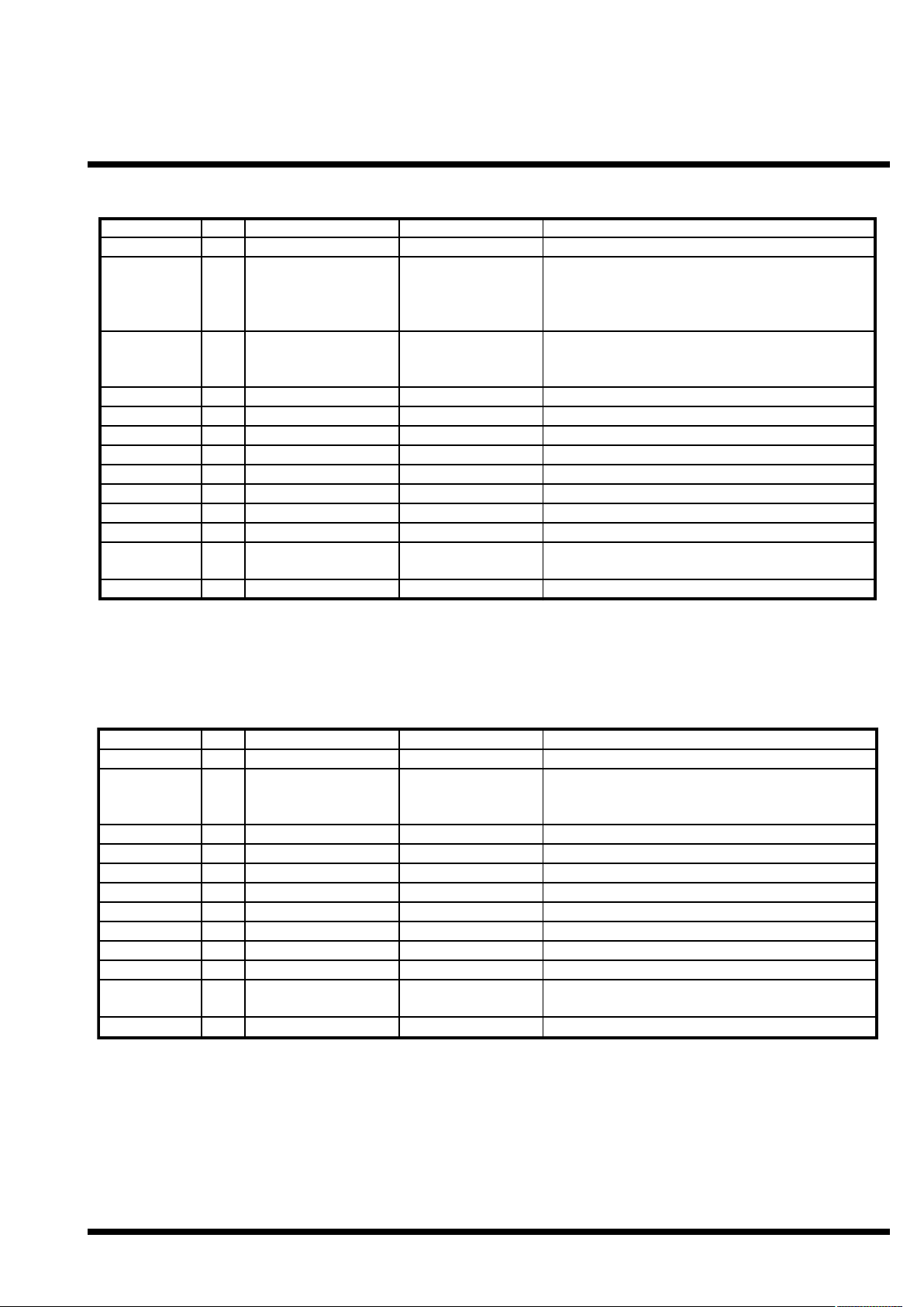
6.1 DC Characteristics
Parameter Min Max Units Remarks
V
cc
I
cc
Operating Voltage
Operating Supply Current (no loading)
4.35 5.25
20
V
mA
I
sb
I
ol
R
up
I
olaux
Suspend mode current
Sink current on output pins
Pull-up Resistance
Sink current into Aux pins
8
25
2
μA
mA
24
50
kΩ
mA
Oscillator off
Vout = 0.4V
Vout = 0.8V
I
ohaux
I
snk
V
ith
Source current from Aux pins
Combined sink current into all pins
Input Threshold Voltage
USB Interface
40%
V
oh
V
ol
V
di
V
cm
Static output high
Static output low
2.7
Differential Input sensitivity
Differential Input common Mode Range
0.2
0.8
2
70
mA
mA
60% Vcc
Vout > Vcc-2V
Cummulative across all ports
3.6
0.3
V
V
2.5
V
V
15kΩ±5% to GND
|(D+)-(D-)|
V
se
C
in
I
io
R
pu
Single Ended Transceiver Threshold
Transceiver capacitance
0.8
Hi-Z State Data Line Leakage
Bus Pull-up resistance
-10
1.274
R
pd
Bus Pull-down resístance 14.25
2.0
20
V
pF
10
1.326
μAkΩ0V < Vin < 3.3V, Hi-Z State
1.3kΩ±2% to Vcc *
15.75 kΩ 15kΩ±5%
V 1.1.0, July 1st 2010 for Chip Revision V1.0.4.0 and up
Page 10

Code Mercenaries
10
JJ
JJ
oo
oo
yy
yy
WW
WW
aa
aarrrrrrrriiii
oo
oorrrr
6.2 AC Characteristics
Parameter Min Max Units Remarks
t
r
USB Driver Characteristics
Transition rise time 75 ns CLoad = 200pF
t
r
t
f
t
f
t
rfm
Transition rise time
Transition fall time 75
Transition fall time
Rise/Fall Time matching 80
300 ns
ns
300
125
ns
%
CLoad = 600pF
CLoad = 200pF
CLoad = 600pF
V
crs
t
drate
t
djr1
Output signal crossover voltage
USB Data Timing
1.3
Low Speed Data Rate
Receiver data jitter tolerance
1.4775
-75
t
djr2
t
deop
t
eopr2
t
eopt
Receiver data jitter tolerance
Differential to EOP transition skew
-45
-40
EOP width at reeiver
Source EOP width
670
1.25
2.0 V
1.522575MBit/s
ns To next transition
45
100
ns
ns
1.50
ns
μs
For paired transitions
Accepts as EOP
t
udj1
t
udj2
Differential driver jitter
Differential driver jitter
-95
-150
95
150
nsnsTo next transition
To paired transition
V 1.1.0, July 1st 2010 for Chip Revision V1.0.4.0 and up
Page 11

Code Mercenaries
11
JJ
JJ
oo
oo
yy
yy
WW
WW
aa
aarrrrrrrriiii
oo
oorrrr
7. Ordering information
The chips listed here are standard products. Customized chips are available on request.
7.1 Packaging info
PDIP24 chips come in tubes with 16 chips each.
SOIC24 chips come in tubes with 31 chips each.
To assure best handling and shipping safety please order the chips in full tubes.
7.2 USB VendorID and ProductID
By default all JoyWarrior chips are shipped with the USB VendorID of Code Mercenaries ($7C0 or
decimal 1984) and a fixed ProductID. On request chips can be equipped with the customers VendorID
and ProductID. VendorIDs can be obtained from the USB Implementers Forum <www.usb.org>
Customized chips are subject to minimum order quantities, contact <sales@codemercs.com> for details.
7.3 Product IDs, Versions and Production Status
Following is the current status for all JoyWarrior variants and the Product ID information. ProductIDs are
independent of the package type. The MouseWarrior chips listed are based on the JoyWarrior core.
Partname Order Code Description Package
JoyWarrior24 GP 32
JoyWarrior24 GP 32
JW20GP32-P
JW20GP32-S
Gamepad controller supports up to 32 buttons, 8x4 matrix
Gamepad controller supports up to 32 buttons, 8x4 matrix
PDIP24
SOIC24
JoyWarrior24 A8-8
JoyWarrior24 A8-8
JoyWarrior24 A8-16
JoyWarrior24 A8-16
JW24A8-8-P
JW24A8-8-S
Joystick controller, 3 axis, 8 bit, autocenter/cal, up to 8 buttons
Joystick controller, 3 axis, 8 bit, autocenter/cal, up to 8 buttons
JW24A8-16-P
JW24A8-16-S
Joystick controller, 3 axis, 8 bit, autocenter/cal, up to 16 buttons
Joystick controller, 3 axis, 8 bit, autocenter/cal, up to 16 buttons
PDIP24
SOIC24
PDIP24
SOIC24
JoyWarrior24A8L
JoyWarrior24A8L
JoyWarrior24A10L
JoyWarrior24A10L
JW24A8L-P
JW24A8L-S
Joystick controller, four axes 8 bit, auxiliary outputs
Joystick controller, four axes 8 bit, auxiliary outputs
JW24A10L-P
JW24A10L-S
Joystick controller, three axes 10 bit, auxiliary outputs
Joystick controller, three axes 10 bit, auxiliary outputs
JoyWarrior20 GP 8
JoyWarrior20 A8-8
JoyWarrior20 A8-16
JoyWarrior20 A10-8
end-of-life
end-of-life
don't use for new designs
don't use for new designs
end-of-life
end-of-life
don't use for new designs
don't use for new designs
PDIP24
SOIC24
PDIP24
SOIC24
JoyWarrior20 A10-16 end-of-life don't use for new designs
Partname Product ID Current Shipping Version Status
JoyWarrior20 GP 8
JoyWarrior24 GP 32
$1100
$1101
V1.0.3.B
V1.0.3.3
end of life
active
JoyWarrior24 A8-8
JoyWarrior24 A8-16
JoyWarrior20 A10-8
JoyWarrior20 A10-16
$1104
$1105
V1.0.3.0
V1.0.3.0
$1108
$1109
V1.0.3.B
V1.0.3.B
active
active
end of life
end of life
JoyWarrior20 A8-8
JoyWarrior20 A8-16
JoyWarrior24RC
MouseWarrior24J8
$110A
$110B
V1.0.3.B
V1.0.3.B
$1110
$1112
V1.0.3.5
V1.0.3.3
JoyWarrior24F8
MouseWarrior24F8
MouseWarrior24H8
JoyWarrior24F14
$1113
$1114
V1.0.3.8
V1.0.3.8
$1115
$1116
V1.0.3.7
V1.0.4.0
end of life
end of life
active
active
active
active
active
active
JoyWarrior24A8L
JoyWarrior24A10L
$1117
$1118
V1.0.4.1
V1.0.4.1
active
active
V 1.1.0, July 1st 2010 for Chip Revision V1.0.4.0 and up
Page 12

Code Mercenaries
12
JJ
JJ
oo
oo
yy
yy
WW
WW
aa
aarrrrrrrriiii
oo
oorrrr
8 Typical application for JoyWarrior24 GP32
A
A
B
B
C
C
D
D
E
E
F
F
1 1
2 2
3 3
4 4
March 16th 2010
2.3
Close JP1 for 12 direct connected buttons
Button Matrix, or buttons closing to Gnd
JoyWarrior24GP32
Button Matr ix needs decoupling
diodes at ever y s witch:
100nF
C1
1K3
R1
CC
CC
ii
ii
rr
rr
cc
cc
uu
uu
ii
ii
tt
tt
::
::
VV
VV
ee
ee
rr
rr
ss
ss
ii
ii
oo
oo
nn
nn
::
::
DD
DD
aa
aa
tt
tt
ee
ee
::
::
DD
DD
rr
rr
aa
aa
ww
ww
nn
nn
bb
bb
yy
yy
::
::
PP
PP
aa
aa
gg
gg
ee
ee
::
::
FF
FF
uu
uu
nn
nn
cc
cc
tt
tt
ii
ii
oo
oo
nn
nn
::
::
Rev. Date By Change Sign.
Code Mercenaries
GND
D+
D-
+5V
432
1
RightLeftDown
Up
JP1
Gnd PullToGnd
Vcc
X0/B0
X1/B1
X2/B2
X3/B3
X4/B4
X5/B5
X6/B6
X7/B7
Right
Left
Down
Up
Direct
NC
D+
D-
Vreg
JW24GP32
Y0/B8
Y1/B9
Y2/B10
Y3/B11
1234242322215206197188
17
9
14
10
12
13
16
15
11
Yn
Xn
V 1.1.0, July 1st 2010 for Chip Revision V1.0.4.0 and up
Page 13

Code Mercenaries
13
JJ
JJ
oo
oo
yy
yy
WW
WW
aa
aarrrrrrrriiii
oo
oorrrr
8.1 Typical application for JoyWarrior24 A8-8
30.9.2002
V1.0
Cl ose JP1 to di sabl e auto centeri ng and auto cali brati on
JoyWarri or 24A8- 8
C2
4n7F
C1
100nF
R1
1k3
GND
D+
D-
+5V
4
3
2
1
USB
100kΩ
Z
100kΩ
Y
100kΩ
X
B0
B1
B2 B3 B4
B5
B6 B7
CC
CC
ii
ii
rr
rr
cc
cc
uu
uu
ii
ii
tt
tt
::
::
VV
VV
ee
ee
rr
rr
ss
ss
ii
ii
oo
oo
nn
nn
::
::
DD
DD
aa
aa
tt
tt
ee
ee
::
::
DD
DD
rr
rr
aa
aa
ww
ww
nn
nn
bb
bb
yy
yy
::
::
PP
PP
aa
aa
gg
gg
ee
ee
::
::
FF
FF
uu
uu
nn
nn
cc
cc
tt
tt
ii
ii
oo
oo
nn
nn
::
::
Rev. Date By Change Si gn.
Code Mercenaries
JP1
D+
D-
A0
A1
XR1
XR2
YR1
YR2
ZR1
ZR2
B0
B1
B2
B3
VssPullToGND
Vcc
NC
Raw
JJ
JJ
WW
WW
22
22
44
44
AA
AA
88
88
--
--
88
88
VREG
B7B6B5
B4
11
17818
7
16
15
14
13
12
1
2
3
4
24
23
22
21
20
6
19
9
10
5
V 1.1.0, July 1st 2010 for Chip Revision V1.0.4.0 and up
Page 14

Code Mercenaries
14
JJ
JJ
oo
oo
yy
yy
WW
WW
aa
aarrrrrrrriiii
oo
oorrrr
8.2 Typical application for JoyWarrior24 A8-16
Button Matri x needs decoupli ng
di odes at ever y sw i tch:
30.9.2002
JoyWarri or 24A8- 16
Button Matrix
V1.0
Close JP1 to disable auto centeri ng and auto cali bration
4n7F
C2
100nF
C1
1k3
R1
GND
D+
D-
+5V
4
3
2
1
USB
100kΩ
Z
100kΩ
Y
100kΩ
X
CC
CC
ii
ii
rr
rr
cc
cc
uu
uu
ii
ii
tt
tt
::
::
VV
VV
ee
ee
rr
rr
ss
ss
ii
ii
oo
oo
nn
nn
::
::
DD
DD
aa
aa
tt
tt
ee
ee
::
::
DD
DD
rr
rr
aa
aa
ww
ww
nn
nn
bb
bb
yy
yy
::
::
PP
PP
aa
aa
gg
gg
ee
ee
::
::
FF
FF
uu
uu
nn
nn
cc
cc
tt
tt
ii
ii
oo
oo
nn
nn
::
::
Rev. Date By Change Si gn.
Code Mercenaries
JP1
D+
D-
A0
A1
XR1
XR2
YR1
YR2
ZR1
ZR2
X0
X1
X2
X3
VssPullToGND
Vcc
NC
Raw
JJ
JJ
WW
WW
22
22
44
44
AA
AA
88
88
--
--
11
11
66
66
VREG
Y3Y2Y1
Y0
11
17818
7
16
15
14
13
12
1
2
3
4
24
23
22
21
20
6
19
9
10
5
Yn
Xn
V 1.1.0, July 1st 2010 for Chip Revision V1.0.4.0 and up
Page 15

Code Mercenaries
Code Mercenaries
15
KK
KK
ee
ee
yy
yy
WW
WW
aa
aarrrrrrrriiii
oo
oorrrr
Pre Release 1.1, June 24th 1999
15
JJ
JJ
oo
oo
yy
yy
WW
WW
aa
aarrrrrrrriiii
oo
oorrrr
8.3 Typical application for JoyWarrior24A8L
A
A
B
B
C
C
D
D
E
E
F
F
G
G
H
H
I
I
1 1
2 2
3 3
4 4
5 5
6 6
AGND is the r ef er ence point f or a st ar ground f or a ll analog par ts
Marc h 16th 2010
JoyWarr ior 24A8L
1.0
Closing J1 enables dir ect c onnected butt ons.
Butt on Matr ix needs decoupling diodes at every s witch:
Button Matr ix
or di rect connected Buttons
J1
Auxiliary Outputs
C1
100nF
R1
1K3
CC
CC
ii
ii
rr
rr
cc
cc
uu
uu
ii
ii
tt
tt
::
::
VV
VV
ee
ee
rr
rr
ss
ss
ii
ii
oo
oo
nn
nn
::
::
DD
DD
aa
aa
tt
tt
ee
ee
::
::
DD
DD
rr
rr
aa
aa
ww
ww
nn
nn
bb
bb
yy
yy
::
::
PP
PP
aa
aa
gg
gg
ee
ee
::
::
FF
FF
uu
uu
nn
nn
cc
cc
tt
tt
ii
ii
oo
oo
nn
nn
::
::
Rev. Date By Change Sign.
Code Mercenaries
GND
D+
D-
+5V
432
1
USB
C5
100nF
R3
10Ω
X Y Z
C3
10μF
R4
10Ω
C4
100nF
C7
10nF
C8
10nF
C9
10nF
C6
10μF
Gnd PullToGnd
Vcc
X0/B0
X1/B1
X2/B2
X3/B3
Y0/B4
Y1/B5
Y2/B6
Y3/B7
/CS
SCLK
Din
Dout
Direct
NC
D+
D-
VREG
JW24A8L
Aux0
Aux1
Aux2
Aux3
1234242322215206197188
17
9
14
10
12
13
16
15
11
REFOUT
REFIN
CH3
CH2
CH1
CH0/CS
SCLK
DIN
DOUT
SSTRB
/SHDN
MM
MM
AA
AA
XX
XX
11
11
11
11
11
11
33
33
VDD
COMAGNDDGND
8
7
432
1
16
1415131112
6
10
9
5
RZ
C10
10nF
Yn
Xn
V 1.1.0, July 1st 2010 for Chip Revision V1.0.4.0 and up
Page 16

Code Mercenaries
16
JJ
JJ
oo
oo
yy
yy
WW
WW
aa
aarrrrrrrriiii
oo
oorrrr
8.4 Typical application for JoyWarrior24A10L
A
A
B
B
C
C
D
D
E
E
F
F
G
G
1
1
2
2
3
3
4
4
5
5
AGND is the reference point for a star ground for all analog parts
March 15th 2010
1.0
JoyWarrior24A10L
Closing J1 enables dir ect connect ed buttons .
Button Matr ix needs decoupling diodes at every switch:
Button Matr ix
or di rect connected B uttons
J1
Auxiliary Outputs
100nF
C1
1K3
R1
CC
CC
ii
ii
rr
rr
cc
cc
uu
uu
ii
ii
tt
tt
::
::
VV
VV
ee
ee
rr
rr
ss
ss
ii
ii
oo
oo
nn
nn
::
::
DD
DD
aa
aa
tt
tt
ee
ee
::
::
DD
DD
rr
rr
aa
aa
ww
ww
nn
nn
bb
bb
yy
yy
::
::
PP
PP
aa
aa
gg
gg
ee
ee
::
::
FF
FF
uu
uu
nn
nn
cc
cc
tt
tt
ii
ii
oo
oo
nn
nn
::
::
Rev. Date By
Change
Sign.
Code Mercenaries
GND
D+
D-
+5V
432
1
USB
100nF
C5
10Ω
R3
X
Y
Z
10μF
C3
10Ω
R4
100nF
C4
10nF
C7
10nF
C8
10nF
C9
REFADJ
VREF
CH3
CH2
CH1
CH0
/CS
SCLK
DIN
DOUT
SSTRB
/SHDN
MM
MM
AA
AA
XX
XX
11
11
22
22
44
44
99
99
VDD
COM
AGND
DGND
9
8
543
2
1
1516141213
7
11
10
6
10μF
C6
Gnd PullToGnd
Vcc
X0/B0
X1/B1
X2/B2
X3/B3
Y0/B4
Y1/B5
Y2/B6
Y3/B7
/CS
SCLK
Din
Dout
Direct
NC
D+
D-
VREG
JW24A10L
Aux0
Aux1
Aux2
Aux3
1234242322215206197188
17
9
14
10
12
13
16
15
11
Yn
Xn
V 1.1.0, July 1st 2010 for Chip Revision V1.0.4.0 and up
Page 17

Code Mercenaries
17
JJ
JJ
oo
oo
yy
yy
WW
WW
aa
aarrrrrrrriiii
oo
oorrrr
9. Package Dimensions
24 Pin PDIP
24 Pin SOIC
V 1.1.0, July 1st 2010 for Chip Revision V1.0.4.0 and up
Page 18

Code Mercenaries
18
JJ
JJ
oo
oo
yy
yy
WW
WW
aa
aarrrrrrrriiii
oo
oorrrr
10. ESD Considerations
JoyWarrior has an internal ESD protection to
withstand discharges of more than 2000V without
permanent damage. However ESD may disrupt
normal operation of the chip and cause it to exhibit
erratic behaviour.
For the typical office environment the 2000V
protection is normally sufficient. Though for
industrial use additional measures may be
necessary.
When adding ESD protection to the signals special
care must be taken on the USB signal lines. The
USB has very low tolerance for additional
resistance or capacitance introduced on the USB
differential signals.
Series resistors of 27Ω may be used alone or in
addition to some kind of suppressor device. In any
case the USB 2.0 specification chapter 6 and 7
should be read for detailed specification of the
electrical properties.
10.1 EMC Considerations
JoyWarrior uses relatively low power levels and so
it causes few EMC problems.
To avoid any EMC problems the following rules
should followed:
• Put the 100nF ceramic capacitor right next to
the power supply pins of the chip and make sure
the PCB traces between the chips power pins
and the capacitor are as short as possible.
• Run the power supply lines first to the capacitor,
then to the chip.
• Make the matrix lines only as long as absolutely
necessary.
• Keep the two USB signal lines close to each
other, route no other signal between them. USB
uses differential signalling so the best signal
quality with lowest RF emission is achieved by
putting these lines very close to each other.
• Adding a ferrite bead to the +5V power supply
line is advisable.
11. Revision History
The initial release version of JoyWarrior is
V1.0.2.0, earlier versions were custom designs not
available for general use.
V1.0.4.1
- First shipping version of JW24A8L and
JW24A10L
V1.0.4.0
- Discontinued JW20 branch of chips.
- Added JW24A8L and JW24A10L
- Added JW24F14 (aka Tomcat) acceleration
sensor.
V1.0.3.B
- Fixed a spurious enumeration problem with
JW20 variants on Linux. JW24 chips are not
affected. On UHCI hosts it was possible that
reading the device descriptors could fail.
Windows and MacOS were not affected due to a
different error recovery method of their system
drivers.
V1.0.3.A
- Customer specific chips, no general release
V1.0.3.9
- Customer specific chips, no general release
V1.0.3.8
- Added MW24F8 variant
- Fixed a race condition in JW24F8 that could
lead to wrong data when values were jittering
around a 256 boundary.
V1.0.3.7
- Added MW24H8 variant
V1.0.3.6
- Added JW24F8 variant
V1.0.3.5
- Added Zhen Hua protocol to JW24RC
V1.0.3.4
- Added customer specific chips
- Changed reset timing for JW20 variants.
- Not a general release!
V1.0.3.3
- Added MouseWarrior24J8.
- Removed jitter filter on JW20A8 and
JW20A10.
- Relaxed timing of matrix scan function of
JW20A8-16 and JW20A10-16.
- Added direct connected button mode on
JW24GP32 allowing 12 buttons connected
pulling to ground instead of using a matrix.
V1.0.3.2
- Release for customer specific chips, not
generally available.
V1.0.3.1
- Fixed a problem in JW24RC that could cause it
not to detect the correct signal polarity of the
PPM signal.
V 1.1.0, July 1st 2010 for Chip Revision V1.0.4.0 and up
Page 19

Code Mercenaries
19
JJ
JJ
oo
oo
yy
yy
WW
WW
aa
aarrrrrrrriiii
oo
oorrrr
V1.0.3.0
- Added JoyWarrior20A8-8, JoyWarrior20A8-16,
and JoyWarrior24RC variants.
- Moved JoyWarrior24GP32 to new silicon
reducing external circuitry and adding the
option for a DIL24 package.
- Improved auto-calibration and -centering on
JoyWarrior24A8 so unused axes with no pots
connected no longer block operation.
V1.0.2.1
- Added JoyWarrior24A8-8 and JoyWarrior24A816 variants.
V1.0.2.0
- Initial general release.
V 1.1.0, July 1st 2010 for Chip Revision V1.0.4.0 and up
Page 20

Code Mercenaries
20
JJ
JJ
oo
oo
yy
yy
WW
WW
aa
aarrrrrrrriiii
oo
oorrrr
Legal Stuff
This document is ©1999-2010 by Code
Mercenaries.
The information contained herein is subject to
change without notice. Code Mercenaries makes
no claims as to the completeness or correctness of
the information contained in this document.
Code Mercenaries assumes no responsibility for
the use of any circuitry other than circuitry
embodied in a Code Mercenaries product. Nor
does it convey or imply any license under patent or
other rights.
Code Mercenaries products may not be used in any
medical apparatus or other technical products that
are critical for the functioning of lifesaving or
supporting systems. We define these systems as
such that in the case of failure may lead to the
death or injury of a person. Incorporation in such a
system requires the explicit written permission of
the president of Code Mercenaries.
Trademarks used in this document are properties of
their respective owners.
Code Mercenaries
Hard- und Software GmbH
Karl-Marx-Str. 147a
12529 Schönefeld OT Grossziethen
Germany
Tel: x49-3379-20509-20
Fax: x49-33790-20509-30
Mail: support@codemercs.com
Web: www.codemercs.com
HRB 9868 CB
Geschäftsführer: Guido Körber, Christian Lucht
V 1.1.0, July 1st 2010 for Chip Revision V1.0.4.0 and up
 Loading...