

Page 1
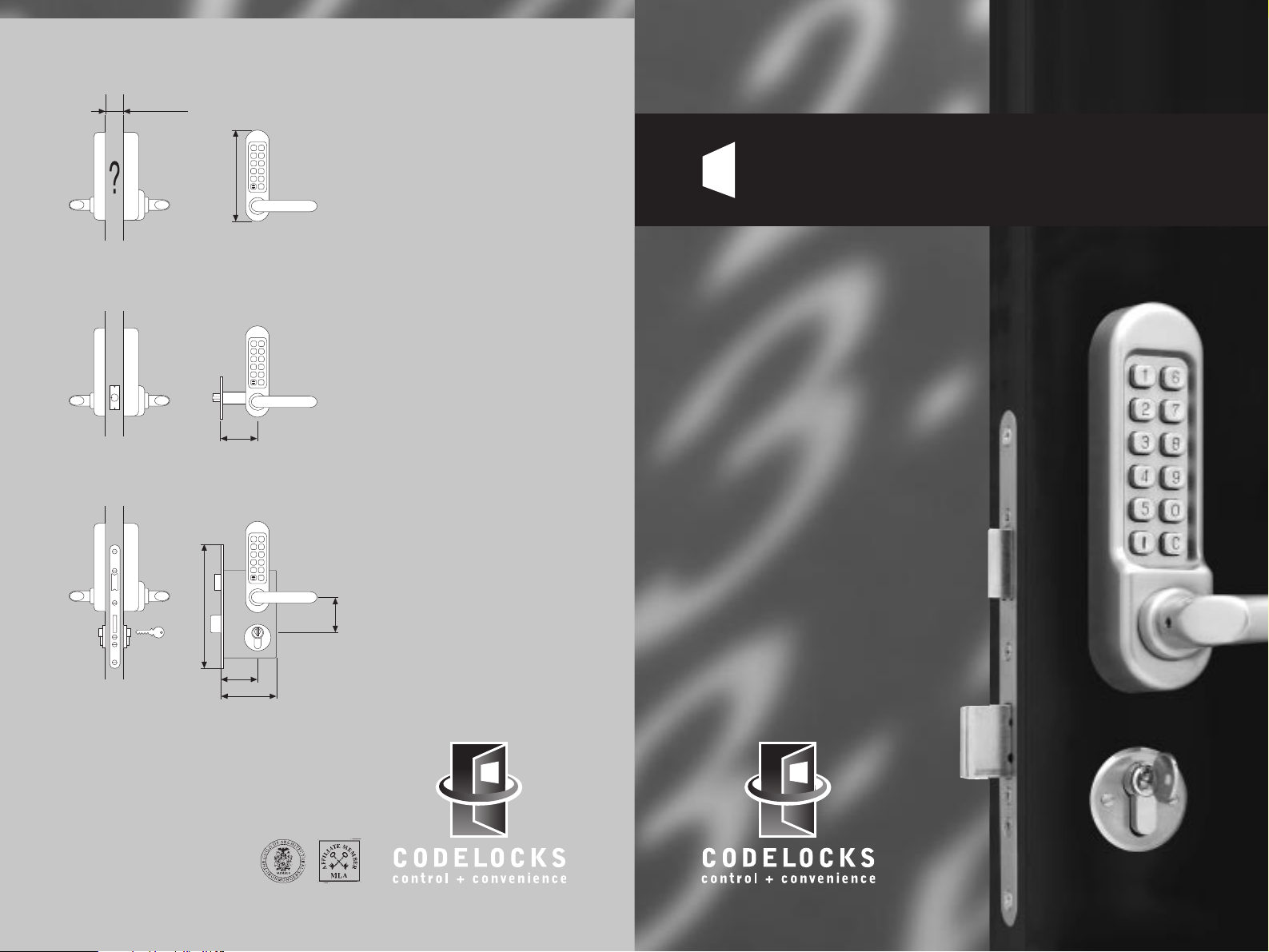
Dimensions
Features
■ Code Free Entry Mode by turning
the slotted button 90 degrees
after entering the code
(models 505, 515, 525 only)
■ Inside handle always retracts the
latch for exit
■ Weather resistant
■ Vandal resistant, with stainless
steel buttons, and clutch
protection if the outside handle
is forced
■ Reversible handles
■ Easy code change as often
as required
■ Fits doors between 35mm and
60mm thick without modification
Features - Model 525 only
■ Split follower lock enables inside
handle to retract latch and
deadbolt simultaneously,
satisfying ‘means of escape’
requirements for exit at all
times. Prevents accidental lock-ins
■ Deadbolt thrown by key to lock
out code users after work hours
■ Key will retract the latchbolt
giving access for admin functions
■ Double Euro-profile cylinder with
3 keys. Any Euro-profile cylinder
may be used
■ On multiple door installations
consideration should be given to
having all cylinders keyed alike,
with restricted key issue, for
ease of management
1
2
3
4
5
6
7
8
9
0
C
178mm
35 — 60mm
Model 500/505
For use with existing lock
1
2
3
4
5
6
7
8
9
0
C
60mm
Model 510/515
With tubular latchbolt
1
2
3
4
5
6
7
8
9
0
C
72mm
235mm
55mm
84mm
Model 520/525
With full ‘Panic Function’
mortice lock & cylinder
2.07.02
INSTALLATION
INSTRUCTIONS
USHbutton 500 series
P
CODELOCKS LTD
Tel 01635 268029 Fax 01635 268031
sales@codelocks.co.uk
www.codelocks.co.uk
Helpline, service & spares
FREEPHONE 0800 393405
Page 2
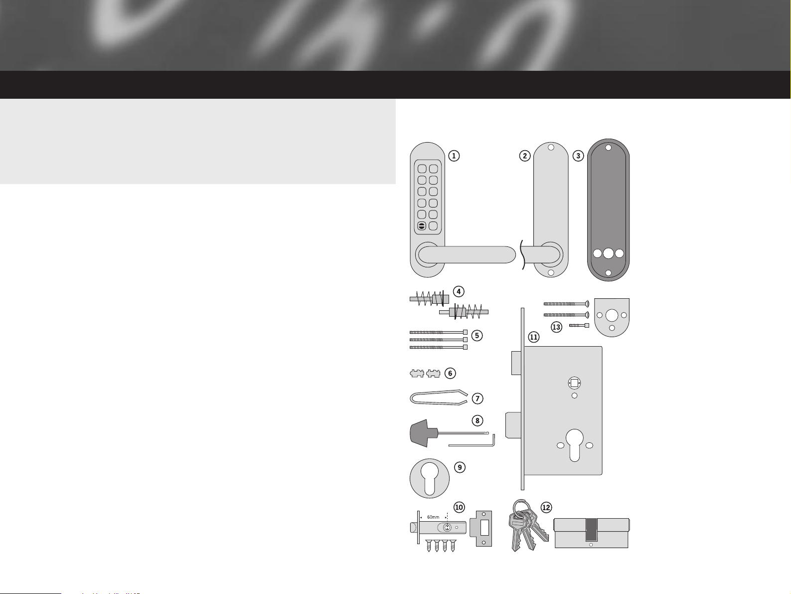
1 Front plate and handle
2 Back plate and handle
3 Neoprene seals x2
4 Two-part spindle with springs
(patent pending)
5 Fixing bolts x2 (1x spare)
6 Spare code tumblers x2
7 Tweezers for code changing
8 Allen keys x2
9 Key way escutcheons
10 Mortice latch, strike & 4 screws
11 2 bolt mortice lock and strike
12 Double Europrofile cylinder & 3 keys
13 Adaptor kit for mortice locks
with horizontal fixings
■ Installation template
■ Code change instructions
■ Code card
■ Power drill
■ Drill bit 20mm
16mm
12mm
■ Phillips screwdriver
■ Chisel 22mm
■ Chisel 25mm
■ Hammer/mallet
■ Stanley knife
■ Adhesive tape, pencil, bradawl
tape measure
PUSHBUTTON 500 SERIES
Check that the contents of your box are correct according to the model.
BOX CONTENTS
Model 500/505 Model 510/515 Model 520/525
✱✱ ✱
✱✱ ✱
✱✱ ✱
✱✱ ✱
✱✱ ✱
✱✱ ✱
✱✱ ✱
✱✱ ✱
2 pairs – 1 pairs
– ✱ –
––✱
––✱
✱ ––
– ✱✱
✱✱ ✱
✱✱ ✱
✱✱ ✱
✱✱ ✱
––✱
✱✱ ✱
– ✱✱
––✱
– ✱✱
– ✱✱
– ✱✱
– ✱✱
TOOLS REQUIRED
On models 505, 515 and 525
note the slotted turn within the
bottom left hand button. If the
slot is in the vertical position it
signifies that a code is needed
each time to operate the lever
handle. Enter the code from
the code card and the lever
handle should turn fully to 35
degrees, and then spring back
to horizontal. Enter the code
again, turn the slot to the
horizontal position and the
lock will be in code-free
access mode. Return the slot
to the vertical position and
after one further free turn the
lock will be in code control
mode again.
Turn the front plate over and
note that the red tipped
tumblers inside correspond to
the code. The code may be
entered in any sequence, i.e.
1370 may be entered as
3710 or any other sequence
of those numbers. There are a
total of 2047 codes available
on the 500, 510 and 520
locks, any of which may be
entered in any order. There
are 1023 codes available on
the 505, 515 and 525.
If you intend to change the
code you should do it, if
convenient, before installing
the lock – see the Code
Change Instructions in the
separate sheet.
CHECK
OPERATION OF
THE CODED
FRONT PLATE
1
6
7
2
3
8
4
9
5
0
C
Page 3

MODEL 500/505 INSTALLATION INSTRUCTIONS
The model 500/505 is intended to replace the conventional door furniture fitted
to an existing mortice latch, or an existing mortice lock which has both a spring
latch and a deadbolt. The square follower should be 8mm square. Any lock and
key mechanism is retained to operate the deadbolt. The latchbolt will only
operate by code, and NOT by key.
A mortice lock case should have holes for fixing bolts to pass through on either
side of the square latch follower and sometimes, additionally, a hole below the
follower. See figure 1 and confirm that your lockcase is compatible with the
500/505 lock plates.
IF YOUR LOCKCASE HAS A
HOLE BELOW THE
FOLLOWER (FIGURE 1 ‘A’),
PROCEED AS FOLLOWS:
step 1
Hold one of the black
neoprene seals against the
door, perfectly vertically, with
the large hole accurately over
the follower. Mark the top and
bottom holes on the door
face, and repeat the
procedure on the other side
of the door. Remove the lock.
At both points drill a 12mm
hole through the door. Drill
from both sides for greater
accuracy and to avoid
splintering out of the door
face. Check that the existing
spindle hole is at least 18mm
diameter. Replace the lock.
8mm latch follower
'A'
Through fixing hole
below the follower
FIGURE 1 – lockcase
'B'
Through fixing holes
either side of the follower
step 2
Take the 2-part spindle, with
the springs in place. Note that
one has a RED coloured face,
and the other a BLUE face. If
your door is hinged on the
right, viewed from outside,
then fit the BLUE spindle into
the latch follower on the
outside, with the colour on
TOP. Fit the RED spindle to
the inside, again with the
colour on TOP. For a left hand
hung door fit the spindles the
other way around, with the
colours on TOP.
step 3
Check that the lever handles
are correctly fitted for the
hand of door. To change the
hand of a lever handle, loosen
the grub screw with the small
Allen key, reverse the lever
handle and fully tighten the
grub screw.
step 4
Cut two of the black socket
head screws to the required
length for your door.
Approximate overall length
should be door thickness plus
25mm, to allow about 10mm
of threaded bolt to enter the
outside plate.
step 1
Hold one of the black
neoprene seals against the
door, perfectly vertically, with
the large hole accurately over
the follower. Mark the top hole
and the holes on either side
of the follower, and then
repeat the procedure on the
other side of the door.
Remove the lock.
Drill the 3x 12mm holes from
both sides for greater
accuracy, and to avoid
splintering out of the door
face. Check that the existing
spindle hole is at least 18mm.
step 5
Apply the front and back
plates, with the neoprene
seals in position, against the
door, over the protruding
ends of the spindle.
step 6
Fix the two plates together
using the socket head bolts,
starting with the top fixing.
Ensure that the two plates are
truly vertical and then tighten
the bolts using the ‘T’ shaped
Allen key. Do not use
excessive force.
step 7
Before closing the door,
enter the code and ensure
that the latchbolt will retract
when the lever handle is
depressed. Now check the
operation of the inside lever
handle. If there is any binding
of the handles or latch then
loosen the bolts slightly and
reposition the plates slightly
until the correct position is
found, and then re-tighten
the bolts.
IF YOUR LOCKCASE ONLY
HAS HOLES ON EITHER
SIDE OF THE FOLLOWER
(FIGURE 1 ‘B’), PROCEED
AS FOLLOWS:
step 2
Take the 2-part spindle, with
the springs in place. Note that
one has a RED coloured face,
and the other a BLUE face. If
your door is hinged on the
right, viewed from outside,
then fit the BLUE spindle into
the latch follower on the
outside, with the colour on
TOP. Fit the RED spindle to
the inside, again with the
colour on TOP. For a left hand
hung door fit the spindles the
other way around, with the
colours on TOP.
Page 4

step 4
Take the adaptor kit, item 13
on the contents page. Cut the
two M5 countersunk head
bolts to length to suit the
door thickness; i.e. door
thickness plus a maximum of
10mm (no more than 5mm
should enter the front plate).
Hold the front plate, with a
neoprene seal, against the
door over the protruding
spindle. From the other side
of the door, with the other
neoprene seal in position, fix
the adaptor plate to the front
plate. Before tightening up the
fixings make sure that there is
an equal gap all around
between the plate and the rim
of the neoprene seal to allow
the back plate housing to fit
over the adaptor plate. Do not
use excessive force.
step 5
Be sure that the handle is
fixed to the back plate, and
then remove the plate which
covers the handle spring.
Cut one of the long black
socket head screws to the
required length for your door.
Approximate overall length
should be door thickness plus
25mm, to allow about 10mm
of threaded bolt to enter the
front plate. Use this screw,
with the ‘T’ shaped Allen key,
to fix the back plate to the
front plate through the TOP
holes. Using the 20mm socket
head screw fix the back plate
through the BOTTOM holes to
the adaptor plate. Do not use
excessive force.
step 6
Before closing the door,
enter the code and check
that the latchbolt retracts
when the lever handle is
depressed. Now check the
operation of the inside lever
handle. If there is any binding
of the handles or latch then
loosen the top and bottom
bolts and reposition the plates
slightly until the correct
position is found, and then
re-tighten the bolts.
step 3
Check that the lever handles
are correctly fitted for the
hand of door. To change the
hand of a lever handle, loosen
the grub screw with the small
Allen key, reverse the lever
handle and fully tighten the
grub screw.
MODEL 510/515 INSTALLATION INSTRUCTIONS
The model 510/515 has a tubular, deadlocking, mortice latch and may be used
as a new installation on a door, or where an existing latch is to be replaced.
step 1
Lightly mark a height line on
the edge and both faces of the
door, and on the door jamb, to
indicate the top of the lock
when fitted.
Crease the template along the
dotted line, and tape it to the
door with the top in line with
the height line.
Mark the 2x 12mm and the
1x 20mm holes. Mark the
centre of the door edge on the
Centre Line of Latch. Remove
the template and apply it to
the other side of the door,
aligning it accurately with the
first Centre Line of Latch mark.
Mark the 3 holes again.
step 4
Put the latch into the hole and,
holding it square to the door
edge, draw around the
faceplate. Remove the latch
and score the outline with a
Stanley knife to avoid splitting
when chiselling. Chisel a
rebate to allow the latch to fit
flush to the surface.
step 2
Keeping the drill level and
square to the door, drill a hole
to accept the latch.
step 3
Keeping the drill level and
square to the door, drill the
12mm and 20mm holes from
both sides of the door to
increase accuracy and to avoid
splintering out the door face.
step 5
Fix the latch with the wood
screws, with the bevel
towards the door frame.
step 6
Take the 2-part spindle, with
the springs in place. Note that
one has a RED coloured face,
and the other a BLUE face. If
your door is hinged on the
right, viewed from outside,
then fit the BLUE spindle into
the latch follower on the
outside, with the colour on
TOP. Fit the RED spindle to
the inside, again with the
colour on TOP. For a left hand
hung door fit the spindles the
other way around, with the
colours on TOP.
step 7
Check that the lever handles
are correctly fitted for the
hand of door. To change the
hand of a lever handle, loosen
the grub screw with the small
Allen key, reverse the lever
handle and fully tighten the
grub screw.
Page 5

MODEL 520/525 INSTALLATION INSTRUCTIONS
Model 520/525 is a complete locking unit with all the parts necessary for a
new installation, or the total replacement of an existing lock.
IMPORTANT The mortice lock provided (fig. 2) has features which are not found in most other locks
and so it is recommended that you familiarise yourself with them as follows:
A. When necessary the hand
of the latchbolt can be
changed by removing the
three screws holding the
faceplate to the lockcase
and reversing the latchbolt.
B. Put the key in the cylinder
and insert it centrally into
the lockcase. Fix it in
position with the long bolt
through the faceplate. It
should now be possible to
project and retract the
deadbolt with the key, and
also to retract the latchbolt.
C. The square latchbolt
follower is in 2 parts: the
inside ‘panic function’
follower will retract the
latchbolt and also the
deadbolt when it is
projected. The effect of
this is to ensure that it is
not possible to accidentally
lock someone in a room
because the deadbolt is
projected. The outside
follower will always retract
the latchbolt whenever the
lever handle is depressed
after a correct code is
entered, but it will
not
retract the deadbolt.
The hand of the ‘panic
function’ is determined as
follows: the grub screws
on the split follower facing
the code side must be
removed. This prevents
the outside handle
retracting the deadbolt.
NEVER remove grub
screws from both sides at
the same time.
All door locks should be
installed with a degree of
precision to ensure that all
components are horizontally
and vertically accurate in
relation to each other, and in
relation to the door.
Do not install the lock where
it will involve cutting into a
joint between the door stile
and a mid-rail.
step 8
Fitting the strike plate.
NB: The plunger beside the
latchbolt deadlocks it to
protect against manipulation
or ‘shimming’. The strike plate
must be accurately installed
so that the plunger CANNOT
enter the aperture when the
door is closed, even if it is
slammed shut.
Position the strike plate on
the door frame so that it lines
up with the flat of the
latchbolt, and NOT the
plunger. Mark the positions of
the fixing screws, and draw
around the aperture of the
strike plate. Chisel out the
aperture 15mm deep to
receive the latchbolt. Fix the
strike plate to the surface of
the frame using only the top
fixing screw. Gently close the
door and check that the
latchbolt enters the aperture
easily, and is held without too
much ‘play’. When satisfied,
draw around the outline of the
strike plate, remove it and cut
a rebate to enable the
faceplate to lie flush with the
surface. Re-fix the strike plate
using both screws.
step 9
Apply the front and back
plates, with the neoprene
seals in position, against the
door, over the protruding
ends of the spindle.
step 10
Fix the two plates together
using the socket head bolts,
starting with the top fixing.
Ensure that the two plates
are truly vertical and then
tighten the bolts using the ‘T’
shaped Allen key. Do not use
excessive force.
step 11
Before closing the door,
enter the code and ensure
that the latchbolt will retract
when the lever handle is
depressed. Now check the
operation of the inside lever
handle. If there is any binding
of the handles or latch then
loosen the bolts slightly and
reposition the plates slightly
until the correct position is
found, and then re-tighten
the bolts.
Page 6

step 12
Before closing the door,
enter the code and check that
the latchbolt will retract when
the lever handle is depressed.
Now check the operation of
the inside lever handle. If there
is any binding of the handles
or the latch then loosen the
bolts and reposition the plates
slightly until the correct
position is found, and then
re-tighten the bolts.
step 13
Fit the double Euro-profile
cylinder and secure it with
the long screw through the
faceplate. Fit the cylinder
escutcheons.
step 14
Check that the deadbolt will
project and retract by key,
and that the key will also
retract the latchbolt.
Check that the inside lever
handle WILL retract the
deadbolt simultaneously with
the latchbolt.
Check that the outside lever
handle WILL NOT retract the
deadbolt.
step 15
Mark a vertical line on the door
jamb half the door thickness
away from the door stop. This
gives the centre line of the
strike plate. Align the Strike
Plate Template with the height
line, with the arrow heads
aligned with the centre line.
Mark the fixing holes, and draw
around the apertures for the
latchbolt and the deadbolt.
Chisel out the latch aperture to
12mm deep, and the deadbolt
aperture to 22mm deep.
Fix the strike plate with the top
screw only and gently close the
door. Ensure that the latchbolt
enters its aperture easily and
holds the door without too much
‘play’. When satisfied, draw
around the final position of the
strike plate, remove it, and cut a
rebate to allow it to fit flush to
the surface. Re-fix the strike with
both screws.
step 9
Check that the lever handles
are correctly fitted for the
hand of door. To change the
hand of a lever handle, loosen
the grub screw with the small
Allen key, reverse the lever
handle and fully tighten the
grub screw.
step 10
Apply the front and back
plates, with the neoprene
seals in position, against the
door, over the protruding
ends of the spindle.
step 11
Fix the two plates together
using the socket head bolts,
starting with the top fixing.
Ensure that the two plates are
truly vertical and then tighten
the bolts using the ‘T’ shaped
Allen key. Do not use
excessive force.
step 5
Drill the holes from both sides
of the door to improve
accuracy and to avoid
splintering out the door face.
step 4
Fold the template accurately
along the dotted line and tape it
to the door face with the top in
line with the height line, and the
fold on the door edge. Mark the
centres of all the holes to be
drilled. Remove the template
and repeat the procedure on the
other face of the door.
step 3
Apply tape to the 16mm drill
bit at 90mm from the tip to
act as a depth guide when
drilling the mortice holes.
Ensure the drill is level and
parallel to the door face and
drill the holes as indicated on
the template. Remove the
remaining wood with a chisel
to leave a clean mortice hole
which accepts the lockcase
without forcing. With the lock
in the mortice make sure that
the forend is parallel with the
door edge and mark the
outline of the forend plate.
Cut the outline with a Stanley
knife to avoid splitting out
when chiselling. Chisel a
rebate sufficient to accept the
forend flush with the surface.
22mm bolt throw
Bolt through fixings
for lever furniture
Grub screws
Split follower
Bolt through fixings
for escutcheons
Easy to reverse
key action latchbolt
FIGURE 2
520/525 lockcase
step 1
Lightly mark a height line on
the edge and both faces of the
door, and the door jamb, to
indicate the top of the lock
when fitted. Mark a line down
the centre of the door edge,
extending above the height line
and 300mm below it.
step 2
Hold the template against the
edge of the door with the top
in line with the height line, and
with the arrows in line with the
‘Centre of Door Edge’ line.
Mark the positions of the
fixing screws, and the holes
to be drilled for the mortice.
step 8
Take the 2-part spindle, with
the springs in place. Note that
one has a RED coloured face,
and the other a BLUE face. If
your door is hinged on the
right, viewed from outside, then
fit the BLUE spindle to the latch
follower on the outside, with
the colour on TOP. Fit the RED
spindle to the inside, again with
the colour on TOP.
For a left hand hung door fit the
spindles the other way around,
with the colours on TOP.
step 6
Install the lockcase in the door.
step 7
Cut two of the black socket
head bolts to the required
length for your door.
Approximate overall length
should be door thickness plus
25mm to allow about 10mm of
threaded bolt to enter the
outside plate.
 Loading...