

Page 1

CL600 Installation Instructions
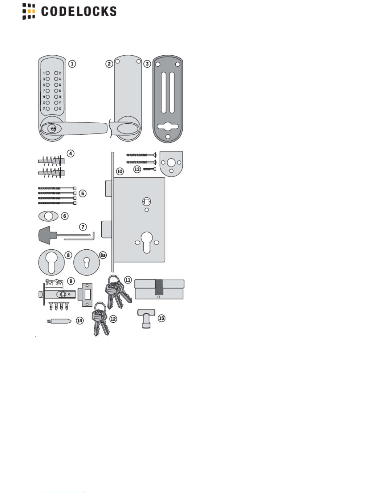
Contents
CHECK THAT THE CONTENTS OF YOUR BOX ARE CORRECT
ACCORDING TO THE MODEL
Model
600/605
Model
610/615
Model
620/625
1 Front plate and handle
2 Back plate and handle
3 Neoprene seals x 2
4 RED & BLUE tipped spindles
5 Fixing bolts x 4 (1 x spare)
6 Front plate cylinder cover
7 Allen keys x 2
8 Euro profile cylinder
escutcheons
1 pair - 1 pair
8
a
Keyhole escutcheons 1 pair - -
9 Mortice latch, strike & 4 screws -
-
102 bolt mortice lock and strike - -
11Double Europrofile cylinder & 3
keys
- -
12Code change keys
13Adaptor kit for mortice locks
with horizontal fixings
- -
14Latch support post -
-
15Code change tool
Installation template
Code change instructions
Code card
Fire Kit (optional) -
(See
page 13)
-
Tools Required for installation:
• Power drill
• Drill bits 30mm (1 / "), 25mm (1"), 20mm ( / "), 16mm ( / ") &
3
16
3
4
5
8
10mm ( / ")
3
8
• Phillips screwdriver
• Chisel - 22mm ( / ")
7
8
• Chisel - 25mm (1")
• Hammer/Mallet
• Stanley knife
• Adhesive tape
• Pencil
• Bradawl
• Tape measure
Find more online at www.codelockssupport.com
Page 1
Page 2
Find more online at www.codelockssupport.com
CHECK OPERATION OF THE CODED FRONT
PLATE
On models CL605, CL615 and CL625 a free passage function is
available. This is identified by a black dot on the bottom left hand ’Z’
button. In normal operation the code needs to be entered every time
to retract the latch. To put the lock into free passage mode, first
press the random factory set code, followed by the passage set
button. The lock will now be in code free access mode. To put the
lock to code access only press the passage set button once followed
by the C button.
See code change instructions on separate sheet.
The code may be entered in any sequence, ie 1370 may be entered
as 0731 or any other sequence of those numbers. There are a total
of 8,191 codes available on the CL600, CL610 and CL620 locks.
There are 4,095 codes available on the CL605, CL615 and CL625
locks.
.
Page 2
Page 3
Find more online at www.codelockssupport.com
Model CL600/605 Installation Instructions
The model CL600/605 is intended to replace the conventional door
furniture fitted to an existing mortice latch, or an existing mortice lock
which has both a spring latch and a deadbolt. The square follower
should be 8mm (5/16”) square. Any lock and key mechanism is
retained to operate the deadbolt. The CL600/605 will only operate
the latchbolt and not the deadbolt. A mortice lock case should have
holes for fixing bolts to pass through on either side of the square
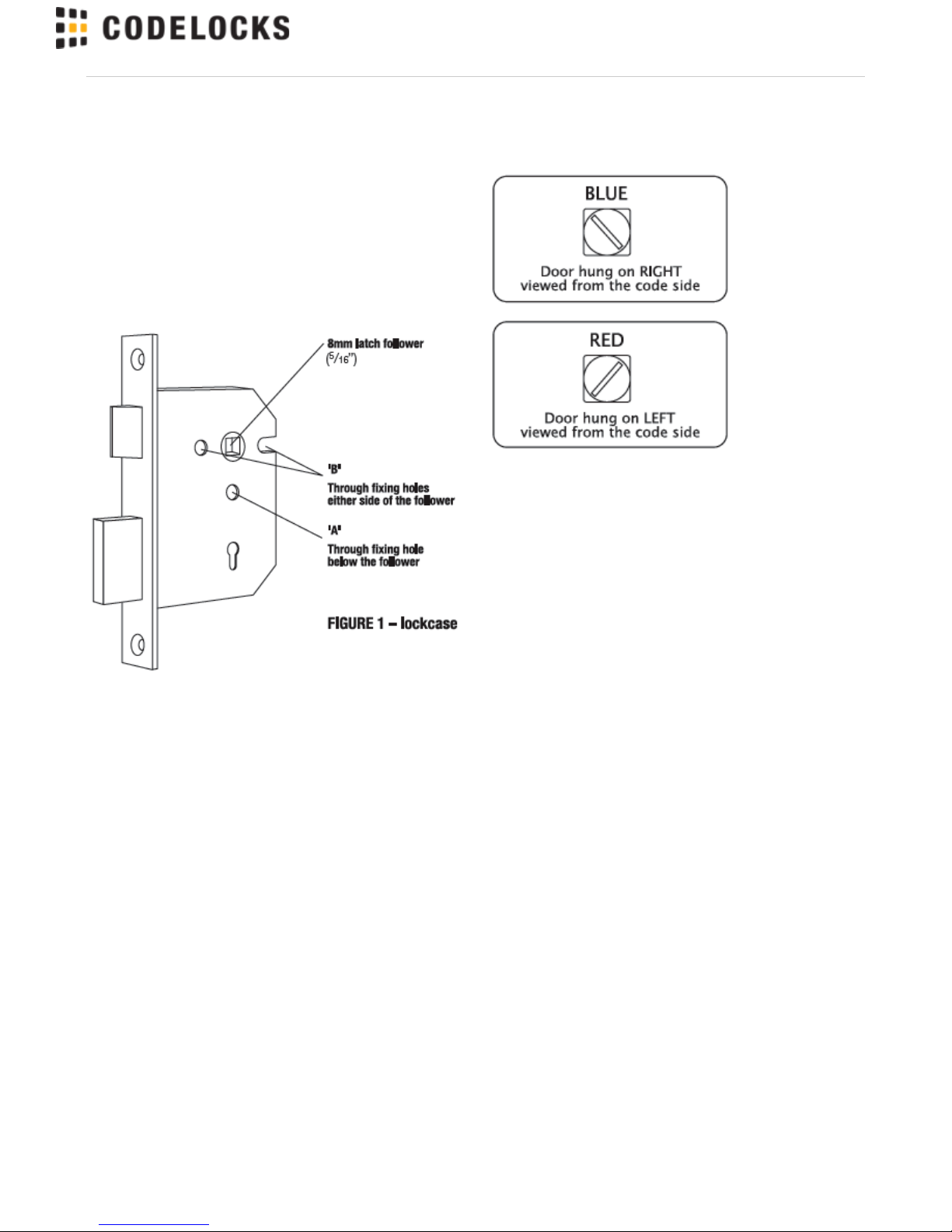
latch follower and sometimes, additionally, a hole below the follower.
See figure 1 and confirm that your lockcase is compatible with the
CL600/605 lock plates.
IF YOUR LOCKCASE HAS A HOLE BELOW THE FOLLOWER
(FIGURE 1 ‘A’), PROCEED AS FOLLOWS:
STEP 1
Hold the neoprene seal with the three fixing holes against the door,
vertically, with the rectangular hole centrally over the follower. Mark
the top and bottom holes on the door face, and repeat the procedure
on the other side of the door. Remove the lock. At three points drill
a10mm ( / ”) hole through the door. Drill from both sides for greater
3
8
accuracy and to avoid splintering out of the door face. Check that
the existing spindle hole is at least 18mm ( / ”) diameter. Refit the
3
4
lock.
IMPORTANT: When using CL600/CL605 front and back plates only,
please test with your selected lock-case to ensure that the latch
retracts fully from the code side without too much resistance. Some
lock-cases have a heavily sprung latch follower designed for use
with un-sprung lever furniture. This heavy springing can defeat the
clutch on our locks.
Please note the code chamber for mechanical locks requires the
lever to be rotated at least 45 degrees to re-set the lock for the next
code user.
Please contact our Codelocks technical department if you are
unsure. Codelocks Limited does not accept responsibility for
products incorrectly specified.
STEP 2
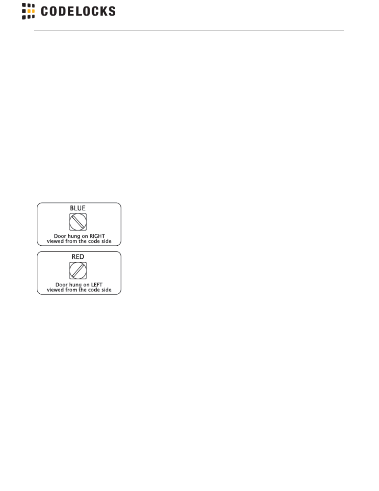
Take the BLUE or RED tipped spindle and fit to the code side
according to the hand of your door (see diagram).
Fit remaining spindle to inside - non code side.
STEP 3
Cut three of the socket head bolts to the required length for your
door. Approximate overall length should be door thickness plus
25mm (1”), to allow about 10mm ( / ”) of threaded bolt to enter the
3
8
outside plate.
STEP 4
Remove plastic insert plug from frontplate. Apply the front and back
plates, with the neoprene seals in position, against the door, over
the protruding ends of the spindle.
STEP 5
Fix the two plates together using the socket head bolts, starting with
the top fixings. Ensure that the two plates are truly vertical and then
tighten the bolts using the ‘T’ shaped Allen key. Do not use
excessive force.
STEP 6
Fit the lever handles to suit the hand of the door. To change the
hand of a lever handle, loosen the grub screw with the small Allen
key, reverse the lever handle and fully tighten the grub screw.
STEP 7
Ensure that the latchbolt retracts after the code is entered and the
lever handle is depressed. Now check the operation of the inside
lever handle. If there is any binding of the handles or latch then
loosen the bolts slightly and reposition the plates until the correct
position is found, and then re-tighten the bolts.
Page 3
Page 4
Find more online at www.codelockssupport.com
IF YOUR LOCKCASE ONLY HAS HOLES ON EITHER SIDE OF
THE FOLLOWER (FIGURE 1 ‘B’), PROCEED AS FOLLOWS:
STEP 1
Hold the neoprene seal against the door, perfectly vertically, with the
rectangular hole centrally over the follower. Mark the top holes and
the holes on either side of the follower if not already drilled, using
adaptor plate as guide, then repeat the procedure on the other side
of the door. Mark an extra hole on the inside of the door in line with
the bottom fixing hole.
Remove the lock.
Drill the 4 x 10mm ( / ”) holes from both sides for greater accuracy,
3
8
and to avoid splintering out of the door face. Check that the existing
spindle hole is at least 18mm ( / ”). Drill the extra 12mm ( / ”) hole
3
4
1
2
5mm ( / ”) deep on the inside of the door to accept the fixing nut on
3
16
the adaptor plate.
Replace the lock.
STEP 2
Take the BLUE or RED tipped spindle and fit to the code side
according to the hand of your door (see diagram).
Fit remaining spindle to inside - non code side.
STEP 3
Take the adaptor kit, item 13 on the contents page. Cut the two M5
countersunk head bolts to length to suit the door thickness; i.e. door
thickness plus a maximum of 10mm ( / ”) (no more than 5mm ( / ”)
3
8
3
16
should enter the front plate). Hold the front plate, with the three hole
neoprene seal, against the door over the protruding spindle. From
the other side of the door, fix the adaptor plate to the front plate
using the two M5 countersunk bolts. Before tightening up the fixings,
make sure that the spindle hole is centrally positioned over the
follower. Do not use excessive force.
STEP 4
Cut two of the long socket head bolts to the required length for your
door. Approximate overall length should be door thickness plus
25mm (1”), to allow about 10mm ( / ”) of threaded bolt to enter the
3
8
front plate. Place the neoprene gasket over the adaptor plate. Use
the screw with the ‘T’ shaped Allen key, to fix the back plate to the
front plate through the TOP holes. Using the 20mm ( / ”) socket
3
4
head bolt fix the back plate through the BOTTOM hole to the
adaptor plate. Do not use excessive force.
STEP 5
Check that the lever handles are correctly fitted for the hand of door.
To change the hand of a lever handle, loosen the grub screw with
the small Allen key, reverse the lever handle and fully tighten the
grub screw.
STEP 6
Before closing the door, enter the code and check that the latchbolt
retracts when the lever handle is depressed. Now check the
operation of the inside lever handle. If there is any binding of the
handles or latch then loosen the top and bottom bolts and reposition
the plates slightly until the correct position is found, and then
re-tighten the bolts.
Page 4
Page 5

Model CL610/615 Installation Instructions
The model CL610/615 has a tubular, deadlocking, mort ice lat ch a
nd m ay be used as a new installation on a door, or where an
existing latch is to be replaced.
When installing on a fire door, fire kit is required. Please refer
to instructions on page 12 and 13.
N.B. Ensure enough room for the latch support post Please
align the template to suit the locks backset: 60mm (2 / ”)
3
8
standard or 70mm (2 / ”).
3
4
STEP 1
Lightly mark a height line on the edge and both faces of the door,
and on the door jamb, to indicate the top of the lock when fitted.
Crease the template (standard) along the dotted line, and tape it to
the door with the top in line with the height line. Mark the 3 x 10mm (
/ ”) and the 1 x 30mm (1 / ”) holes.
3
8
3
16
N.B. When fitting to a door with existing 54mm (2 / ”) through
1
8
hole, only top two 10mm ( / ”) holes need to be marked and
3
8
drilled.
Mark the centre of the door edge on the Centre Line of Latch.
Remove the template and apply it to the other side of the door,
aligning it accurately with the first Centre Line of Latch mark. Mark
the 4 holes again.
N.B. Space required above latch body for cam to rotate.
STEP 2
Keeping the drill level and square to the door, drill a 25mm (1”) hole
in centre of door edge, deep enough to accept the latch.
STEP 3
Keeping the drill level and square to the door, drill the 10mm and
30mm ( / ”-1 / ”) holes from both sides of the door to increase
383
16
accuracy and to avoid splintering out the door face.
STEP 4
Put the latch into the hole and, holding it square to the door edge,
draw around the faceplate. Remove the latch and score the outline
with a Stanley knife to avoid splitting when chiselling. Chisel a
rebate to allow the latch to fit flush to the surface.
STEP 5
Fix the latch with the wood screws, with the bevel towards the door
frame.
STEP 6
Fitting the strike plate. N.B. The plunger beside the latchbolt
deadlocks it, to protect against manipulation or ‘shimming’. The
strike plate must be accurately installed so that the plunger CANNO
enter the aperture when the door is closed, even if it is slammedT
shut. Position the strike plate on the door frame so that it lines up
with the flat of the latchbolt, and NOT the plunger. Mark the
positions of the fixing screws, and draw around the aperture of the
strike plate. Chisel out the aperture 15mm ( / ”) deep to receive the
5
8
latchbolt. Fix the strike plate to the surface of the frame using only
the top fixing screw. Gently close the door and check that the
latchbolt enters the aperture easily, and is held without too much
‘play’. When satisfied, draw around the outline of the strike plate,
remove it and cut a rebate to enable the faceplate to lie flush with
the surface. Re-fix the strike plate using both screws.
Find more online at www.codelockssupport.com
Page 5
Page 6

Find more online at www.codelockssupport.com
STEP 7
Take the BLUE or RED tipped spindle and fit to the code side
according to the hand of your door (see diagram).
Fit remaining spindle to inside - non code side.
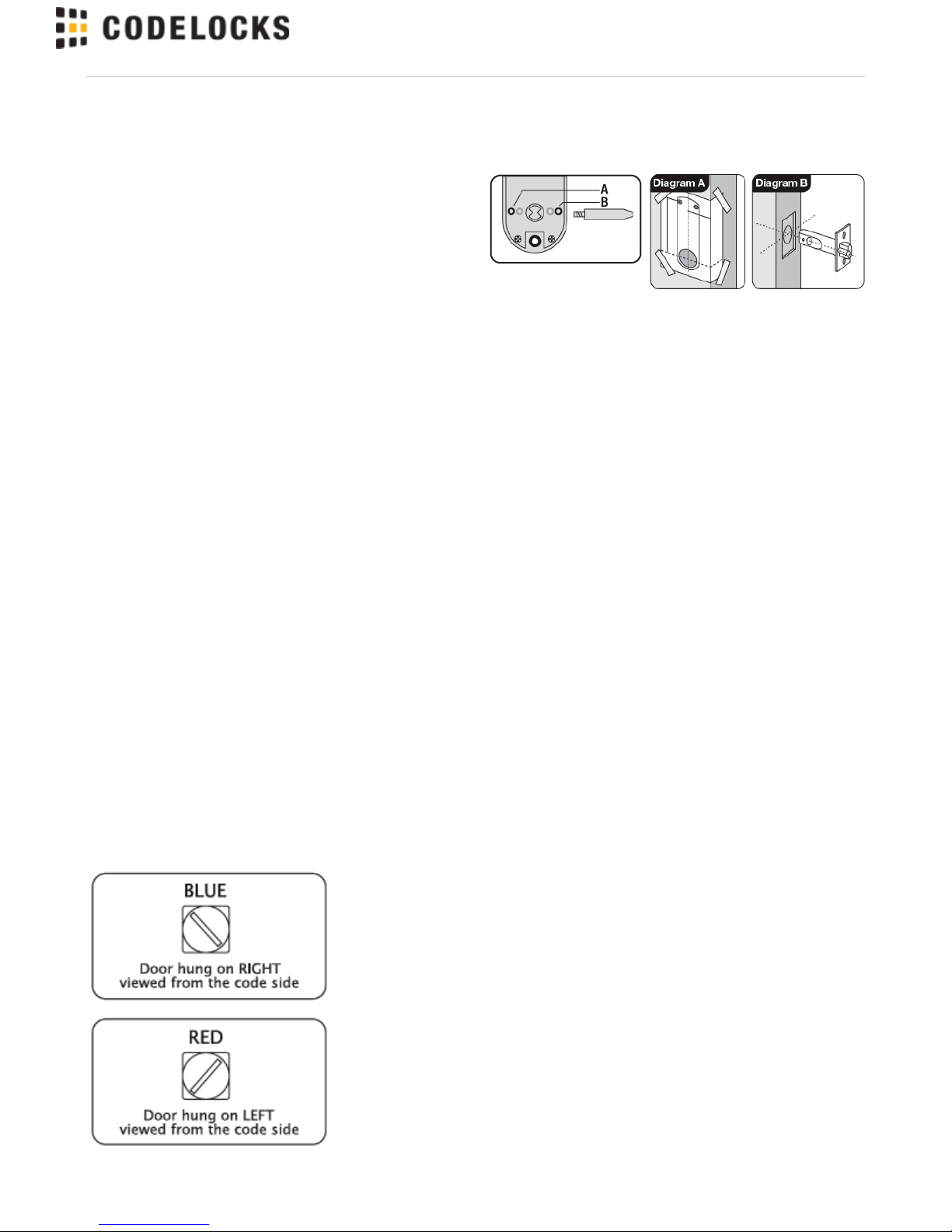
STEP 8
Fit the latch support post into back of the code side front plate
according to the hand of your door, A for a right hand door, or B for
a left hand door (see diagram).
STEP 9
Cut three of the socket head bolts to the required length for your
door. Approximate overall length should be door thickness plus
25mm (1”) to allow about 10mm ( / ”) of threaded bolt to enter the
3
8
outside plate.
STEP 10
Apply the front and back plates, with the neoprene seals in position,
against the door, over the protruding ends of the spindle.
STEP 11
Fix the two plates together using the socket head bolts, starting with
the top fixing. Ensure that the two plates are truly vertical and then
tighten the bolts using the ‘T’ shaped Allen key. Do not use
excessive force.
STEP 12
Check that the lever handles are correctly fitted for the hand of door.
To change the hand of a lever handle, loosen the grub screw with
the small Allen key, reverse the lever handle and fully tighten the
grub screw.
STEP 13
Before closing the door, enter the code and ensure that the latchbolt
will retract when the lever handle is depressed. Now check the
operation of the inside lever handle. If there is any binding of the
handles or latch then loosen the bolts and reposition the plates
slightly until the correct position is found, and then re-tighten the
bolts.
Page 6
Page 7

Find more online at www.codelockssupport.com
Model CL620/625 Installation Instructions
The model CL620/625 has a mortice lock and may be used as a
new installation on a door, or where an existing lock is to be
replaced.
IMPORTANT: The mortice lock provided (fig.2 - page 11) has
features which are not found in most other locks and so it is
recommended that you familiarise yourself with them as follows:
A. When necessary the hand of the latchbolt can be changed by
removing the three screws holding the faceplate to the lockcase,
reverse the latchbolt, and tighten the screws back up, ensuring that
the latchbolt is central.
B. Put the key in the cylinder and insert it centrally into the lockcase.
Fix it in position with the long bolt through the faceplate. It should
now be possible to project and retract the deadbolt with the key, and
also to retract the latchbolt.
C.The square latchbolt follower is in 2 parts: the inside ‘panic
function’ follower will retract the latchbolt and also the deadbolt
when it is projected. The effect of this is to ensure that it is not
possible to accidentally lock someone in a room because the
deadbolt is projected. The outside follower will always retract the
latchbolt whenever the lever handle is depressed after a correct
code is entered, but it will not retract the deadbolt. The hand of the
‘panic function’ is determined as follows: the grub screws on the split
follower facing the code side must be removed. This prevents the
outside handle retracting the deadbolt.
NEVER remove grub screws from both sides at the same time. All
door locks should be installed with a degree of precision to ensure
that all components are horizontally and vertically accurate in
relation to each other, and in relation to the door. Do not install the
lock where it will involve cutting into a joint between the door stile
and a mid-rail.
STEP 1
Lightly mark a height line on the edge and both faces of the door,
and the door jamb, to indicate the top of the lock when fitted. Mark a
line down the centre of the door edge, extending above the height
line and 300mm (12”) below it.
STEP 2
Hold the template against the edge of the door with the top in line
with the height line, and with the arrows in line with the ‘Centre of
Door Edge’ line. Mark the positions of the fixing holes, and the holes
to be drilled for the mortice.
STEP 3
Apply tape to the 16mm ( / ”) drill bit at 90mm (3 / ”) from the tip to
5
8
9
16
act as a depth guide when drilling the mortice holes. Ensure the drill
is level and parallel to the door face and drill the holes as indicated
on the template. Remove the remaining wood with a chisel to leave
a clean mortice hole which accepts the lockcase without forcing.
With the lock in the mortice make sure that the forend is parallel with
the door edge and mark the outline of the forend plate. Cut the
outline with a Stanley knife to avoid splitting out when chiselling.
Chisel a rebate sufficient to accept the forend flush with the surface.
STEP 4
Fold the template accurately along the dotted line and tape it to the
door face with the top in line with the height line, and the fold on the
door edge. Mark the centres of all the holes to be drilled. Remove
the template and repeat the procedure on the other face of the door.
STEP 5
Drill the holes from both sides of the door to improve accuracy and
to avoid splintering out the door face.
STEP 6
Install the lockcase in the door.
STEP 7
Cut three of the socket head bolts to the required length for your
door. Approximate overall length should be door thickness plus
25mm (1”) to allow about 10mm ( / ”) of threaded bolt to enter the
3
8
outside plate.
STEP 8
Take the BLUE or RED tipped spindle and fit to the code side
according to the hand of your door (see diagram).
Fit remaining spindle to inside - non code side.
STEP 9
Apply the front and back plates, with the neoprene seals in position,
against the door, over the protruding ends of the spindle.
Page 7
Page 8

STEP 10
Fix the two plates together using the socket head bolts, starting with
the top fixings. Ensure that the two plates are truly vertical and then
tighten the bolts using the ‘T’ shaped Allen key. Do not use
excessive force.
STEP 11
Check that the lever handles are correctly fitted for the hand of door.
To change the hand of a lever handle, loosen the grub screw with
the small Allen key, reverse the lever handle and fully tighten the
grub screw.
STEP 12
Before closing the door, enter the code and check that the latchbolt
will retract when the lever handle is depressed. Now check the
operation of the inside lever handle. If there is any binding of the
handles or the latch then loosen the bolts and reposition the plates
slightly until the correct position is found, and then re-tighten the
bolts.
STEP 13
Fit the double Euro-profile cylinder and secure it with the long screw
through the faceplate. Fit the cylinder escutcheons.
STEP 14
Check that the deadbolt will project and retract by key, and that the
key will also retract the latchbolt. Check that the inside lever handle
retract the deadbolt simultaneously with the latchbolt. CheckWILL
that the outside lever handle retract the deadbolt.WILL NOT
STEP 15
Mark a vertical line on the door jamb half the door thickness away
from the door stop. This gives the centre line of the strike plate.
Align the Strike Plate Template with the height line, with the arrow
heads aligned with the centre line. Mark the fixing holes, and draw
around the apertures for the latchbolt and the deadbolt. Chisel out
the latch aperture to 12mm ( / ”) deep, and the deadbolt aperture to
1
2
22mm ( / ”) deep. Fix the strike plate with the top screw only and
7
8
gently close the door. Ensure that the latchbolt enters its aperture
easily and holds the door without too much ‘play’. When satisfied,
draw around the final position of the strike plate, remove it, and cut a
rebate to allow it to fit flush to the surface. Re-fix the strike with both
screws.
Find more online at www.codelockssupport.com
Page 8
Page 9
Find more online at www.codelockssupport.com
Fire Kit Installation Instructions
Take time to be precise and finish the job quicker.
Installation holes must be drilled in exactly the correct positions and
precisely at right angles to the door surface. Lock components must
be vertically and horizontally accurate in relation to each other and
to the door.
WEDGE THE DOOR FIRMLY TO PREVENT MOVEMENT WHILST
DRILLING AND CHISELLING.
STEP 1
Lightly mark a height line on the edge and both faces of the door
and on the door jamb, to indicate the top of the lock when fitted.
Crease the template (fire) along the dotted lines and tape it to the
door with the top in line with the height line. Mark the holes to be
drilled. Mark the centre line of latch on to the door edge. Apply the
template to the other side of the door precisely against the height
line and the centre line of latch mark. Mark the holes to be drilled
again. (See diagram A).
STEP 2
Keeping the drill level and straight, drill a 25mm (1”) hole in the
centre of the door edge to accept the latch. Put the latch into the
hole and holding it square to the door edge, draw around the
faceplate. Remove the latch. Starting with the top and bottom cuts,
chisel a rebate to allow the latch faceplate to fit flush with the door
edge.
STEP 3
Keeping the drill level and straight, drill the holes in the door face.
Drill from both sides of the door to increase accuracy and to avoid
damage to the other side when a drill goes right through.
STEP 4
Insert the fire cup into the 54mm (2 / ”) hole.
1
8
N.B. open side of the fire cup to face code side with small bolt
through hole at the bottom.
STEP 5
Reinsert the latch and fix the screws, with the bevel towards the
door frame. (See diagram B).
STEP 6
Fit the spindles to the latch according to the hand of your door. Fit
remaining spindle to inside - non code side. (see diagram below).
Install the spindle washers (item 3) over the flat blade of both
spindles. Use enough washers so they sit flush to the face of the
door without bind when the Codelock is installed.
Step 7
Fit the latch support post to hole adjacent to for a left hand door,A
and adjacent to for a right hand door.B
Step 8
Screw the fixing posts (item 1 on page 13) into the front plate. Place
the outer cover plate to the door with the inner cover plate (item 4)
using the three fixing bolts (item 5).
Step 9
Fix the front plate to the door with the inner cover plate (item 4)
using the three fixing bolts (item 5). Fit the inside handle body to the
inner cover plate using the three short fixing bolts (item 6).
Step 10
Check that the lever handles are correctly fitted for the hand of door.
To change the hand of a lever handle, loosen the grub screw with
the small Allen key, reverse the lever handle and fully tighten the
grub screw.
Step 11
Before closing the door, enter the code and ensure that the latchbolt
will retract when the lever handle is depressed. Now check the
operation of the inside lever handle. If there is any binding of the
handles or latch then loosen the bolts and reposition the plates
slightly until the correct position is found, and then re-tighten the
bolts.
Page 9
Page 10

Find more online at www.codelockssupport.com
Fire Kit Parts
1. Fixing Posts x 3
2. Outer Cover Plate
3. Spindle Washers x 8
4. Inner Cover Plate
5. Fixing Bolts x 3
6. Short Fixing Bolts x 3
7. Fire Latch 70mm (2 / ")
3
4
8. T Strike Plate
9. Fire Cup
Page 10
Page 11

Find more online at www.codelockssupport.com
Back to Back and PK Versions
Back to Back and PK versions - Models CL600/610/615BB &
CL600/605PK
A) The CL600 range is available in Back to Back versions where the
code is on sides of the door.both
To install the Back to Back versions:
Follow instructions as for non back to back versions substituting the
backplate and handle 2, with the coded plate with the through fixing
holes.
Please note that each side may be coded with the same or different
codes.
B) The CL600 range is also available to work with most single point
panic pads or bars. In this format the front code plate only is
supplied with suitable fixing to connect to most single point panic
pads and latches. If in doubt ask.
To install the PK versions:
Step 1.
The position of the CL600PK on the door is determined by the
position of the panic device.
Step 2.
Mark the position of the spindle hole for the panic device on both
sides of the door.
Step 3.
Place the CL600PK gasket against the door with the 20mm ( / ”)
3
4
hole centred over the mark for spindle hole. Using the gasket as a
template mark the 3 x 10mm ( / ”) holes for the through fixing bolts.
3
8
Repeat on the other side of the door.
Step 4.
Drill the 1 x 20mm ( / ”) hole and the 3 x 10mm ( / ”) drilling holes,
3
4
3
8
from both sides to avoid splintering out the face of the door.
Step 5.
Countersink the bottom fixing hole as necessary so that the fixing
bolt lies flush with the door face, underneath the panic device.
Step 6. Fit the lever handle to the CL600 front plate and tighten the
grub screw in the handle. Enter the code of the CL600 front unit and
check that the lever will turn fully – see page 6. operation check.
Step 7.
Fit the CL600 front unit with the 3 fixing bolts. Insert the spindle with
the flat blade into the CL600 front unit, ensuring that the blade is at
the correct angle for the hand of door - see diagram page 8.
Step 8.
Install the panic device and make sure that the CL600 front unit will
fully retract the latch or bolt.
Page 11
Page 12

Dimensions
Model CL600/605 For use with existing lock
Model CL610/615 With tubular latchbolt
Model CL620/625 With full ‘Panic Function’ mortice lock & cylinder
CODELOCKS UK HEADQUARTERS
Tel: +44 (0) 1635 239645
Fax: +44 (0) 1635 239644
sales@codelocks.com
www.codelocks.com
Helpline, service & spares
Freephone: 0800 393 405
II-CL600-v1:0716
CODELOCKS INC US
Tel: +1 714 979 2900
Fax: +1 714 979 2902
sales@codelocks.us
www.codelocks.us
Helpline, service & spares
Toll free: 1.877.codelock
CODELOCKS (Australia) PTY LTD
Tel: +61 2 9882 1009
Fax: +61 2 9882 6030
sales@codelocks.com.au
www.codelocks.com.au
Helpline, service & spares
Toll free: 1800 052 131
Find more online at www.codelockssupport.com
Page 12
 Loading...