

Page 1
Print Page
Download Template
Download Diagram
You are currently in: Codelocks UK > CL6010 Lock Installation
CL6010 Installation Guide
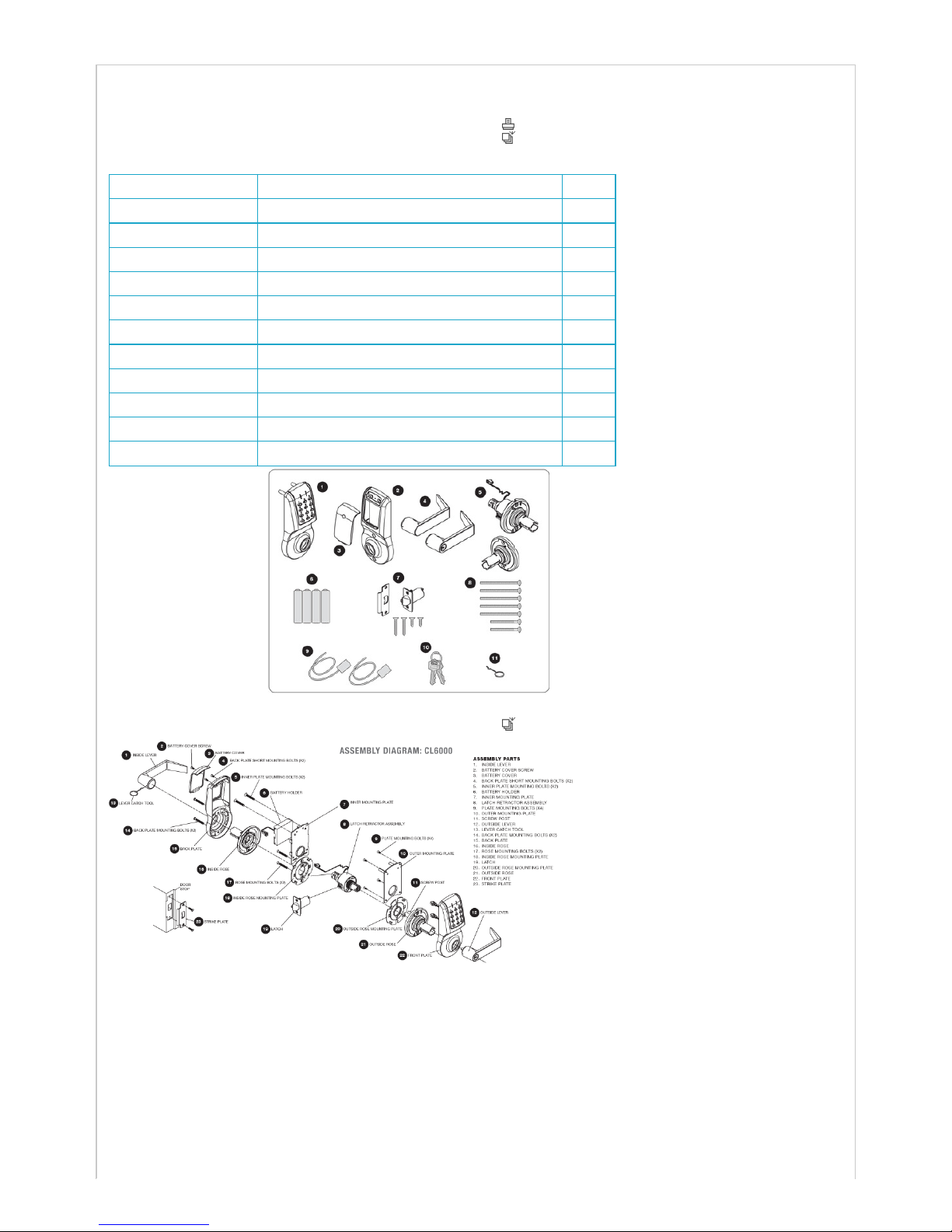
Number relating to picture Item CL6010
1 Front Plate *
2 Back Plate *
3 Battery Cover *
4 Lever Handles *
5 Cylindrical lock assembly, inside and outside rose *
6 1.5v AA Batteries (x4) *
7 Mortice Latch, Strike and 4 screws *
8 8.5 x Mounting Bolts (1 x spare), 2 x brass rose mounting bolts *
9 Cable Connections for REM1 and REM2 *
10 Keys *
11 Lever catch tool *
Tools Required
Power Drill
Drill bits 10mm (3/8"), 25mm (1"),
32mm (1 1/4"), 53mm (21/8")
Philips screwdriver
Hammer / Mallet
Chisel 25mm (1")
Stanley knife
Adhesive tape, pencil, bradawl, tape
measure
Installation of CL6000 Lock
Installation holes must be drilled in exactly the correct positions and precisely at right angles to the door surface. Lock
components must be vertically and horizontally accurate in relation to each other and to the door.
Wedge the door firmly to prevent movement whilst drilling and chiselling
1 MARK DOOR
Codelocks - CL6010 Lock Installation
http://www.codelocks.co.uk/Locks-Technical-Support/CL6010-Lock-Ins...
1 of 5 21/11/2011 11:44
Page 2
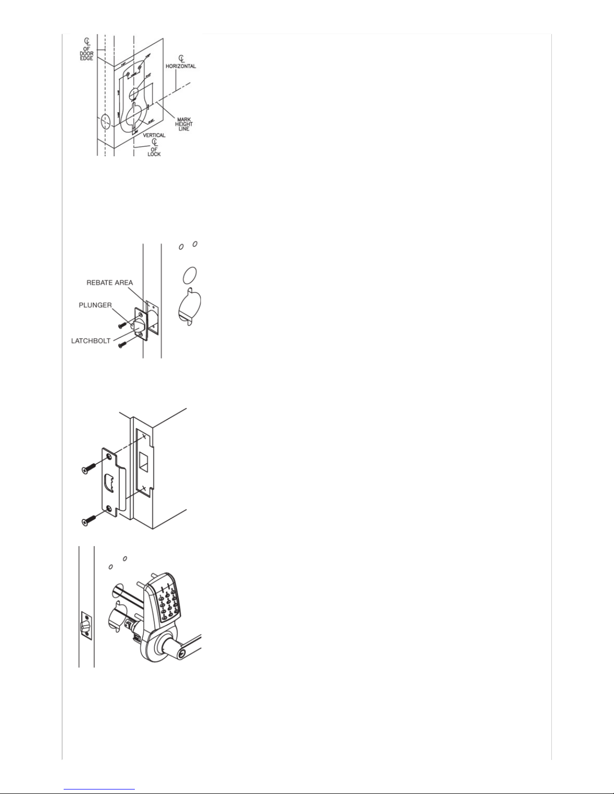
Check local requirements for proper ADA recommended height from finished floor.
Attach template and mark horizontal height line on the edge of the door, both door faces and the door jamb. Mark the holes to
be drilled.
Please note: When installing on a door that is bevelled, make sure you mark the high side of the door.
Verify backset, and mark a vertical center line from edge of door.
Keeping the drill level and straight, drill the holes in the door face on both sides to increase accuracy and to avoid damage to
the other side of the door.
Please note: When installing on a door that is bevelled, make sure you mark the high side of the door and drill from the high
side only.
2 MARK LATCHBOLT HOLE
On horizontal height line drill a 25mm (1") diameter hole in centre of door edge.
Insert latch into hole and with a pencil mark around latch faceplate. Remove latch.
Chisel out at 3mm (1/8") rebate inside marked area to allow the latch face to fit flush with door.
Install the latch with the two woods screws, with the bevel towards the door frame.
3 INSTALLING THE STRIKE PLATE
Note: The plunger beside the latchbolt deadlocks it, to
protect against manipulation or 'shimming'. The strike plate
must be accurately installed so that the plunger CANNOT enter
the aperture when the door is closed, even if it is slammed
shut.
Postion the strike plate on the door frame so that is lines up
with the flat of the latchbolt, and NOT the plunger. Mark the
positions of the mounting screws, and draw around the
aperture of the strike plate. Chisel out the aperture 15mm (3/4")
deep to receive the latchbolt. Install the strike plate to the
surface of the frame using only the top mounting screw. Gently
close the door and check that the latchbolt enters the aperture
easily, and is held without too much 'play'. When satisfied,
draw around the outline of the strike plate, remove it and cut a
rebate to enable the faceplate to lie flush with the surface.
Re-install the strike plate using both screws.
4 INSTALLING THE FRONT PLATE
Position the code side of the lock onto door.
Note: Locks are supplied right handed. To reverse lock hand, see below - Method of changing lock hand.
Make sure latch retractor engages with the tail of the latch.
Pass power cables through upper hole and latch retractor cable through lower hole.
Note: Make sure cables are not trapped.
5 INSTALL INNER ROSE MOUNTING PLATE
Codelocks - CL6010 Lock Installation
http://www.codelocks.co.uk/Locks-Technical-Support/CL6010-Lock-Ins...
2 of 5 21/11/2011 11:44
Page 3

Place the inside rose mounting plate over the spindle ensuring to pass the latch retractor cable through the piercing in the
plate. See diagram.
Secure the inner rose mounting plate against the door and into the front plate using the two fixing bolts. See diagram.
6 INSTALL INNER MOUNTING PLATE
Hold inner mounting plate against inside of door, passing power cables through hole in center of plate. Note: See diagram,
make sure cables are not pinched.
Pass two inner mounting bolts through plate and door into the frontplate and tighten.
7 CONNECT WIRES
Connect the orange/black wire to the latch retractor cable, routing wire under clip provided.
See diagram.
Connect red/black wire to the battery.
Push any excess cable back into hole through door.
8 INSTALL BACK PLATE
Position back plate over retractor spindle, ensuring it fits flush to door.
Secure back plate with two short mounting bolts and two through mounting bolts. See diagram.
Codelocks - CL6010 Lock Installation
http://www.codelocks.co.uk/Locks-Technical-Support/CL6010-Lock-Ins...
3 of 5 21/11/2011 11:44
Page 4

9 INSTALL BATTERIES / INSTALL LEVER
Install batteries provided and fit battery cover. See diagram.
Install inside lever onto spindle according to the hand of door. Lever will be secure when pushed firmly onto spindle with a
"click".
OPERATIONAL CHECK
Before closing door check the operation of you lock:
* Test operation of the lock by depressing internal lever to retract the latch.
* Test operation of the lock by entering Master Code and depressing front lever to retract the latch.
* If either fails, check installation of lock again.
SPECIAL INSTRUCTION
Remote release option
Cables are provided for the REM 1 and
REM 2 terminals on the circuit board. (Fig 1).
REM 1 is for connection to a reception desk push button or a
door intercom system. Pressing the button will cause the Blue
light to flash on the lock and release the lock for the pre-set
time.
REM 2 is for connection to a fire alarm system so as to
release a door in an emergency. This allows rooms, wards,
offices to be easily checked to ensure that no person is
trapped or overlooked during an emergency or a practice fire
drill. When activated REM 2 will maintain the unlocked
condition for 30 minutes, and the Red LED will flash and
BLEEP during this time. The lock will automatically lock again
after 30 minutes. If necessary Program 11 can be used to
re-lock before the end of the 30 minutes.
REM 1 and REM 2 do not require additional power. They are
normally open contract requiring a mementary or maintained
signal to close.
THE METHOD OF CHANGING LOCK HAND, RH TO LH
1 Turn key clockwise and depress lever
catch with tool provided, and pull off lever.
Codelocks - CL6010 Lock Installation
http://www.codelocks.co.uk/Locks-Technical-Support/CL6010-Lock-Ins...
4 of 5 21/11/2011 11:44
Page 5

2 Turn rose and chasis 180 degress for different hand of door.
3 Install lever to desired hand, LH, position at 90 degrees.
4 Turn key clockwise and push lever on fully, until positive
engagement 'click'.
5 Make sure outside lever is securely engaged with spindle.
6 With tool press inside lever catch and pull off lever.
7 Turn inside rose 180 degrees.
8 Install lever to desired hand, LH, position at 90 degrees.
To change from LH to RH reverse the above procedure.
Codelocks - CL6010 Lock Installation
http://www.codelocks.co.uk/Locks-Technical-Support/CL6010-Lock-Ins...
5 of 5 21/11/2011 11:44
 Loading...