

Page 1
10/23/2018 KA-01201 · Customer Self-Service
Home (/) > Knowledge Base - Home (/knowledgebase/) > KA-01201
CL5500 - US Version Installation
Instructions
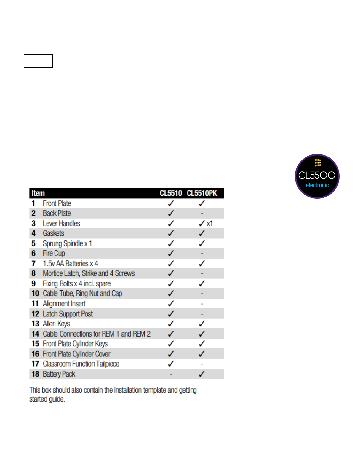
Box Contents
Check the contents of the box are correct
Views: 82
Print
https://support.codelocks.com/knowledgebase/article/KA-01201/en-us 1/8
Page 2

10/23/2018 KA-01201 · Customer Self-Service
FUNCTIONS
https://support.codelocks.com/knowledgebase/article/KA-01201/en-us 2/8
Page 3
10/23/2018 KA-01201 · Customer Self-Service
CL5510 LATCH FUNCTION
Outside handle turns freely without operating the latchbolt. When the code is entered the keypad will flash
blue and the handle will retract the latchbolt. The latch automatically locks the door when closed. The key
will open the door without the code.
OPERATIONS CHECK
You should familiarise yourself with the operation of the lock and check that all the parts work properly.
Remove the battery cover from the back plate and install the 4 x AA cells supplied.
Connect the cables from the front plate and back plate. A BEEP should be heard when you do this. If no
BEEP is heard then check that the batteries are correctly installed.
Place the long spindle in the front plate socket and using finger grip only, test that the spindle is easily
moved 80° in both directions. Leave socket in the centred position.
Enter the factory Master Code #12345678.
The keypad will flash blue and the spindle should not turn as before. After 5 seconds the keypad will flash
red and the spindle should turn easily again. This confirms that the clutch engaged correctly when the code
was entered.
N.B. When the Master Code is entered 3 times consecutively without performing a programming function,
a penalty time of 10 seconds is activated.
Disconnect the cables.
SPECIAL FIXING NOTE
REMOTE RELEASE OPTION
Cables are provided for the REM 1 and REM 2 terminals on the circuit board.
https://support.codelocks.com/knowledgebase/article/KA-01201/en-us 3/8
Page 4

10/23/2018 KA-01201 · Customer Self-Service
REM 1 is for connection to a reception desk push button or a door intercom system. Pressing the button
will cause the keypad to flash blue on the lock and release the lock for the pre-set time.
REM 2 is for connection to the building alarm system to release a door in an emergency. This allows
rooms, wards, offices to be easily checked to ensure that no person is trapped or overlooked during an
emergency evacuation. When activated REM 2 will maintain the unlocked condition for 30 minutes, the
keypad will flash red and BEEP during this time.
The lock will automatically lock again after 30 minutes. If necessary Program 7 can be used to re-lock
before the end of the 30 minutes.
REM 1 and REM 2 do not require additional power. They are normally open contacts requiring a
momentary or maintained signal to close.
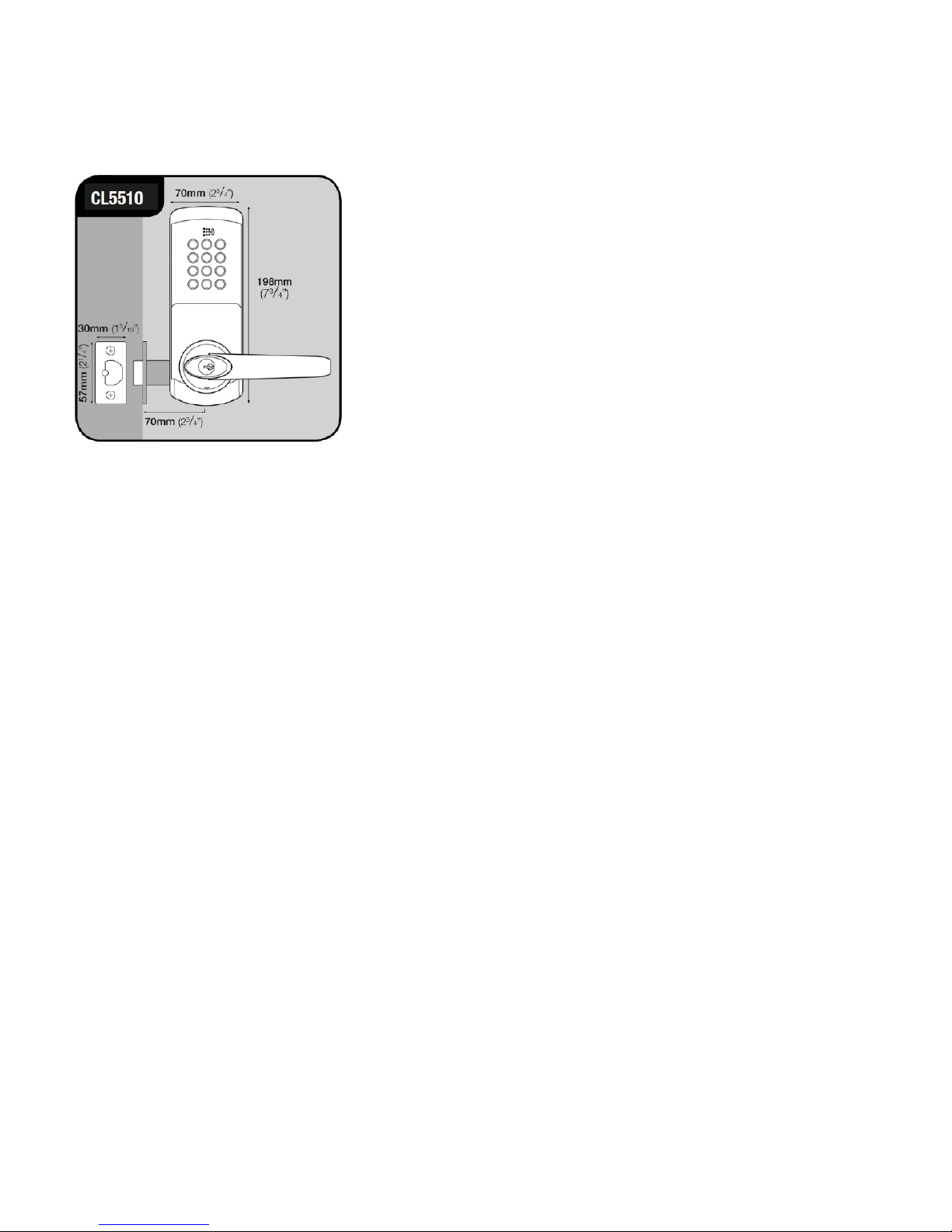
INSTALLATION OF CL5510 LOCKS
Take time to be precise and finish the job quicker.
Installation holes must be drilled in exactly the correct positions and precisely at right angles to the door
surface. Lock components must be vertically and horizontally accurate in relation to each other and to the
door
WEDGE THE DOOR FIRMLY TO PREVENT MOVEMENT WHILST DRILLING AND CHISELLING.
1. Lightly mark a height line on the edge and both faces of the door, to indicate the top of the lock when
fitted. Crease the template along one of the dotted lines - 60mm (2 ⁄”) or 70mm (2 ⁄”) latch - and tape it
to the door with the top in line with the height line. Mark the holes to be drilled. Mark the centre line of
latch on to the door edge. Apply the template to the other side of the door precisely against the height line
and the centre line of latch mark. Mark the holes to be drilled again. (See diagram A).
https://support.codelocks.com/knowledgebase/article/KA-01201/en-us 4/8
Page 5

10/23/2018 KA-01201 · Customer Self-Service
2.Keeping the drill level and straight, drill a 25mm (1”) hole in the centre of the door edge to accept the
latch. Put the latch into the hole and holding it square to the door edge, draw around the faceplate.
Starting with the top and bottom cuts, chisel a rebate to allow the latch faceplate to fit flush with the door
edge. Remove the latch.
3. Keeping the drill level and straight, drill the holes in the door face. Drill from both sides of the door to
increase accuracy and to avoid damage to the other side when a drill goes right through.
4.Insert the fire cup into the 54mm (2 ⁄”) hole. N.B. open side of the fire cup to face code side with small
bolt through hole at the bottom.
5. Re-insert the latch and fix the screws, with the bevel towards the door frame. (See diagram B).
6. Fit the latch support post on the inside of the front plate, in outer hole side A for a left hand hung door
and in outer hole B for a right hand hung door. (See diagram C).
https://support.codelocks.com/knowledgebase/article/KA-01201/en-us 5/8
Page 6

10/23/2018 KA-01201 · Customer Self-Service
7. Screw the cable tube into the front plate, passing the cable through the tube. For doors less than 45mm
(13 /4”) thick screw the tube all the way to the end of the thread. For doors more than 45mm (1 ⁄”) leave
an appropriate amount of thread showing.
Example: For a 60mm (2 ⁄”) thick door leave 15mm (⁄”) of thread showing.
8. Fit the self-adhesive gaskets to the front and back plates. The gaskets provide friction against the door
so that it is not necessary to over-tighten the fixing bolts to provide stability.
9. Remove the five socket head bolts from the back plate (two are found under the battery cover). This will
release the inside fixing plate.
10. Cut the fixing bolts to correct length. Measured from beneath the bolt head, the length should be the
door thickness, plus approximately 15mm (⁄”) to the nearest cutting point of the bolt.
N.B. Always cut the bolts at one of the cutting points so as not to damage a thread. Use the cutting edges
of pliers to crimp strongly several times around the selected cutting point. The surplus end should break off
quite easily.
11. Put the spindle into the latch with the spring on the front plate side of the door.
12.Apply the front plate over the spindle, passing the cable tube through the door and the latch support
post through the latch. Place the fixing plate over the cable tube and spindle. Screw the ring nut onto the
cable tube until finger tight. Fit the alignment insert over the spindle. Screw the fixing bolts through to the
front plate. (See diagram D)
https://support.codelocks.com/knowledgebase/article/KA-01201/en-us 6/8
Page 7

10/23/2018 KA-01201 · Customer Self-Service
13.Check that the spindle turns freely, and the latch retracts and projects smoothly, with the alignment
insert in place. If it is tight, loosen the fixing bolts slightly and adjust the position of the fixing plate until
the spindle will turn freely. Tighten the fixing bolts. Test the spindle again. Do not over-tighten the bolts as
this may cause the door to distort and affect the lock function. PLEASE REMOVE THE ALIGNMENT
INSERT.
14.Connect the cables, storing any excess cable within the door. Screw end cap onto cable tube. Then
install the batteries.
15. Fit the back plate over the fixing plate using the four socket head screws.
16. Fit the cylinder cover and outside handle to the front plate.
17. Fit the inside handle to the back plate.
18. The inside handle will now retract the latchbolt. The outside handle will turn freely without retracting
the latch. Enter the factory Master Code #12345678. The keypad will flash blue and the outside handle will
now retract the latch.
19. Fitting the strike plate
Position the strike plate on the door frame so that the aperture lines up with the flat of the latchbolt, and
NOT the plunger. Mark the positions of the fixing screws and draw around the aperture of the strike plate.
Chisel out the aperture to 15mm (⁄”) deep to receive the latchbolt. Fix the strike plate to the surface of the
frame using only the top fixing screw. Gently close the door and check that the latchbolt enters the
aperture easily, and is held without too much ‘play’. When satisfied, draw around the outline of the strike
plate, remove it and cut a rebate to enable the strike plate to lie flush with the surface. Re-fix the strike
plate using both screws.
https://support.codelocks.com/knowledgebase/article/KA-01201/en-us 7/8
Page 8

10/23/2018 KA-01201 · Customer Self-Service
N.B. The plunger beside the latchbolt deadlocks it to protect against manipulation or ‘shimming’. The
strike plate must be accurately installed so that the plunger CANNOT enter the aperture when the door is
closed, even when it is slammed shut.
INSTALLATION OF CL5510PK
1. The position of the Codelocks CL5510 front unit on the door is determined by the position of the panic
device.
2. Mark the position of the spindle hole for the panic device on both sides of the door.
3. Place the gasket against the door with the 20mm (⁄”) hole centred over the mark for spindle hole.
Using the gasket as a template mark the 3 x 8mm (⁄”) holes for the through fixing bolts. Repeat on the
other side of the door.
4. Drill the 2 x 20mm (⁄”) holes and the 3 x 8mm (⁄”) holes, drilling from both sides to avoid splintering
out the face of the door. Attach the seal and insert the spindle in the back of the keypad. Offer the lock up
to the door and feed the power cable through the door and connect the battery pack on the inside.
5. Countersink the bottom fixing hole as necessary so that the fixing bolt lies flush with the door face,
underneath the panic device. Now fit the two top fixing bolts. Using the wood screw provided, fit the
battery pack on the inside of the door.
6. Fit the lever handle to the CL5510 front unit and tighten the socket head screw in the handle. Enter the
code of the CL5510 front unit and check that the lever will turn fully.
7. Install the panic device and make sure that the Codelocks front unit will fully retract the latch or bolts.
Please note: the spindle may need to be cut to suit the door thickness and engagement with both
the Codelock and panic device.
II-CL5510-CLINC-V1:0716
© 2018 Codelocks Ltd. All rights reserved.
Keywords: Lock Locks Codelock Codelocks Locker Program Programming Instruction Instruct Help
Support Troubleshoot Troubleshooting Sequence Sequences Install Installation Parameters Settings
Setting CL 5500 CL5500
https://support.codelocks.com/knowledgebase/article/KA-01201/en-us 8/8
 Loading...