

Page 1
Print Page
Download Template
You ar e curr ently in: Codelocks UK > CL520 Lock Installat ion G uide
CL520 Installation Guide
Box Contents
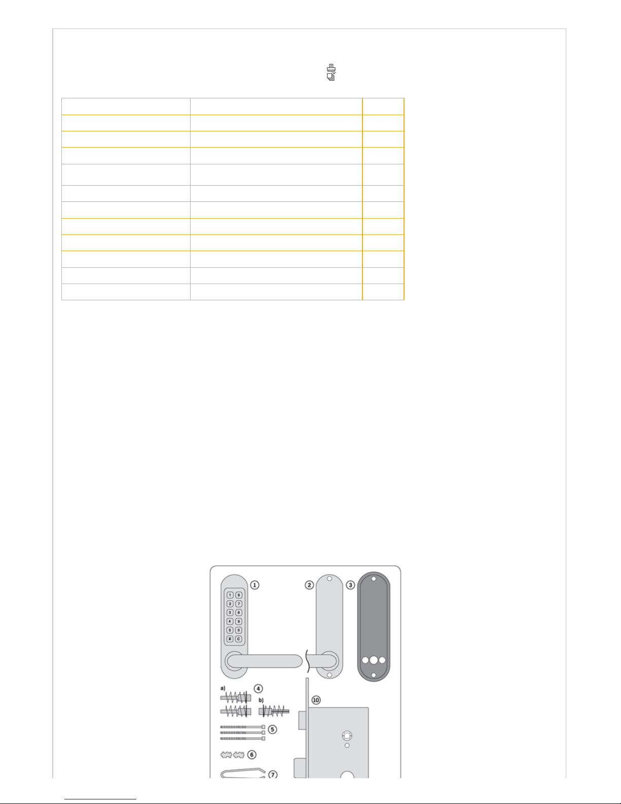
Check the contents of the box are correct accor ding to the model.
Number relating to picture Item CL520
1 Front Plate and handle *
2 Back Plate and handle *
3 Neoprene seals x 2 *
4
Spindles :
a) RED and BLUE tipped spindles
b) Butterfly spindle
*
*
5 Fixing bolts x 2 (1 x spare) *
6 Spare co de tu mblers x 2 *
7 Tweezers for code changing *
8 Allen k eys x 2 *
9 1 pair euro profile cylinder esc utcheons *
10 2 bolt mortice lock and str ike *
11 Double europrofile cylinder & 3 keys *
Tools Required
Power Drill
Drill bit 30mm, 20mm, 16mm, 12mm
Philips s crew driv er
Hammer / mallet
Chisel 22mm
Chisel 25mm
Stanley knife
Adhes ive tape, penc il, br adawl, tape meas ure
Check operation of the coded front plate
Turn the front plate over and note that the red tipped
tumblers inside corres pond to the code. The code
may be entered in any sequenc e, i.e. 1370 may be
entered as 3710 or any other sequenc e of those
numbers. T here are a total of 2,047 codes available,
any of which may be entered in any order.
If you intend to change the code you s hould do it, if
convenient, before installing the lock – see the Code
Change instructions.
Model CL520 is a c omplete lock ing unit with all the
parts nec essary for a new installation, or the total
replacement of an existing lock.
IMPORTANT T he mortice lock pr ovided (fig.2) has
features which are not found in most other locks and
so it is recommended that you familiarise yourself with
them as follows:
A. When nec ess ary the hand of the latc hbolt c an be
changed by removing the three screws holding the
faceplate to the lockcas e. Revers e the latchbolt,
ensuring that the latc hbolt is centr al, replace the
faceplate.
B. Put the k ey in th e c ylinde r a nd ins ert it c entrally into
the lockcas e. Fix it in position with the long bolt
through the faceplate. It should now be possible to
project and r etract the deadbolt with the key, and also
to retract the latchbolt.
Page 2
C. The square latchbolt follower is in 2 parts: the inside ‘panic function’ follower will retract the latchbolt and also the deadbolt
when it is projected. The effect of this is to ensure that it is not possible to accidentally lock someone in a room because the
deadbolt is projected. T he outside follower will always r etrac t the latchbolt whenever the lever handle is depress ed after a
correct code is entered, but it will not retract the deadbolt.
The hand of the ‘panic function’ is determined as follows: the grub screws on the split follower facing the code side must be
removed. This prevents the outside handle retracting the deadbolt.
NEVER remove the grub screws from both sides at the s ame time.
All door loc ks should b e ins talled with a degr ee of precis ion to ens ure that all c ompone nts are hor izontally and v ertically
accur ate in relation to each other , and in relation to the door.
Do not install the lock where it will involve cutting into a joint between the door stile and a mid-rail.
1. Lightly mark a height line on the edge and both faces of the door , and the door jamb, to indicate the top of the lock w hen
fitted. Mark a line down the centre of the door edge, extending above the height line and 300mm below it.
2. Hold the template against the edge of the door w ith the top in line with the height line, and with the arrows in line with the
‘Cent re of Door Edge’ line. Mar k the positio ns of the fixing scr ews, and the hole s to be d rilled for t he mor tice.
3. Apply tape to the 16mm drill bit at 90mm from the top to ac t as a depth guide when dr illing the mortice holes. Ensure the dr ill
is lev el an d para llel to the do or face and drill the hole s as indicat ed on t he t emplate. Rem ove the r emaining wood with a chis el to
leav e a c lean mortic e hole w hich acc epts the lock case wit hout forc ing. With the loc k in t he mor tic e ma ke s ure th at t he for end is
parallel with the door edge and mark the outline of the forend plate. Cut the outline with a Stanley knife to av oid splitting out
when chiselling. Chisel a rebate sufficient to accept the forend flush with the surface.
4. Fold the template acc urately along the dotted line and tape it to the door fac e with the top in line with the height line, and the
fold on the door edge. Mark the centres of all the holes to be drilled. Remove the template and repeat the procedure on the
other face of the door.
5. Drill the holes from both s ides of the door to improve ac curacy and to avoid splintering out the door face.
6. Install the lockcase in the door.
7. Cut two of the black socket head bolts to the required length for your door . Approximate ov erall length should be door
thickness plus 25mm to allow about 10mm of threaded bolt to enter the outside plate.
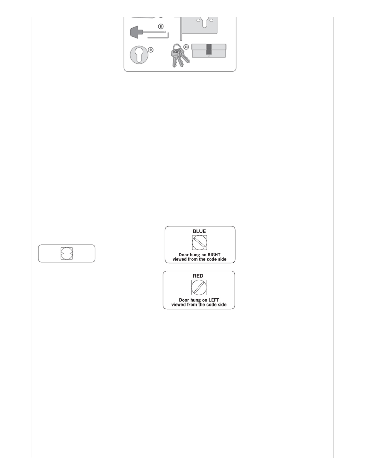
8. Take the BLUE or RED tipped spindle and fit to the code s ide
accor ding to the hand of your door ( see diagram).
Fit the butterfly spindle to the inside, non-code side.
9. Check that the lever handles are c orrec tly fitted for the hand of door. To c hange the hand of a lever handle, loosen the grub
screw with the small Allen key, reverse the lever handle and fully tighten the grub screw.
10. Apply the front and bac k plates , with the neoprene s eals in position, against the door, over the protruding ends of the spindle.
11. Fix the two plates together us ing the soc ket head bolts, starting with the top fixing. Ensure that the tw o plates are tr uly
vertical and then tighten the bolts using the ‘T’ shaped Allen key. Do not use excessive force.
12. Before clos ing the door, enter the c ode and check that the latc hbolt will retract when the lev er handle is depressed. Now
check the operation of the inside lever handle. If there is any binding of the handles or the latch then loosen the bolts and
reposition the plates slightly until the correct position is found, and then re-tighten the bolts.
13. Fit the double europrofile cy linder and sec ure it with the long sc rew thr ough the faceplate. F it the cylinder es cutc heons.
14. Check that the deadbolt will project and retr act by key , and that the k ey will also retract the latchbolt. Chec k that the inside
lever handle WI LL r etrac t the dea dbolt simulta neously with the latc hbolt.
Check that the outside lever handle WILL NOT retract the deadbolt.
15. Mark a vertic al line on the door jamb half the door thicknes s away from the door stop. This gives the centre line of the s trike
plate. Align the strike plate template with the height line, with the arrow heads aligned with the centre line. Mark the fixing holes,
and draw around the apertures for the latc hbolt and the deadbolt. Chisel out the latch aperture to 12mm deep, and the deadbolt
aperture to 22mm deep.
Fix the strike plate with the top screw only and gently close the door. Ensure that the latchbolt enters its aperture easily and
holds the door without too muc h ‘play’. When satisfied, draw around the final position of the str ike plate, remov e it, and cut a
rebate to allow it to fit flush to the surface. Re-fix the strike with both screws.
Page 3

 Loading...