

Page 1
A
B
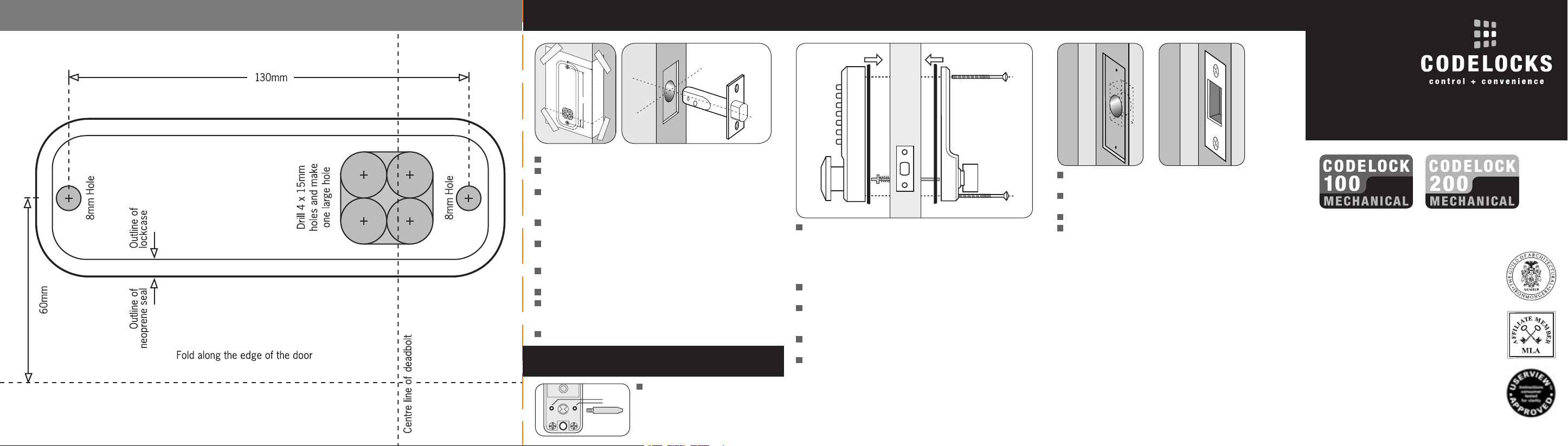
T E M P L A T E 4. FIXING THE LOCK 5. FIXING THE KEEPER PLATE
2. APPLY THE TEMPLATE
INSTALLATION INSTRUCTIONS
Crease the template along the Door Edge line and tape it to the door.
Mark the 2 x 8mm holes, and the 4 x 15mm holes. Mark the
centre of the door edge on the Centre Line of Deadbolt.
Apply the template to the other side of the door, aligning it with the
first mark in the middle of the door edge, and mark the 2 x 8mm
holes and the 4 x 15mm holes again.
Keeping the drill level and square to the door, drill the holes from
both sides to avoid splintering out the door face.
Use a chisel to clear the 4 x 15mm holes into a single square hole.
Positioning and fixing the deadbolt
Drill a 25mm hole, 90mm deep, on the mark on the centre of the
door edge. Be careful to keep the drill level and square to the door.
Put the deadbolt into the hole and draw around the faceplate.
Remove the deadbolt. Score the outline with a Stanley
knife prior to chiselling a 3mm deep rebate to accept the
faceplate flush to the door.
Fix the deadbolt with the wood screws.
3. DEADBOLT SUPPORT POST
Fit the deadbolt support post in
hole A for a right hand hung door,
or B for a left hand hung door. Your
door is right handed if, viewed from
outside, the hinges are on the right.
The spring loaded spindle (pat app) will fit doors between
55mm and 70mm thick. For doors less than 55mm remove
the 15mm break-off end of the spindle. The spindle will
then fit doors between 40mm and 55mm. The spring keeps
the spindle firmly engaged and prevents it moving out of
engagement with either of the plates.
Insert the spindle, with the spring to the outside, through the
slot in the deadbolt.
Cut the fixing bolts to suit the door thickness, allowing at
least one, but no more than two, threaded sections to enter
the lock case.
Hold the lock case and the back plate, with the seals, onto
the door with the spindle in position.
Using the fixing bolts screw everything together, first through
the top, and then through the bottom hole of the back plate.
Before final tightening make sure that the lock is vertical,
and test the mechanism to ensure that it is all moving easily.
DO NOT CLOSE THE DOOR UNTIL YOU ARE SURE THAT
THE CODE WORKS. DO NOT overtighten the fixing bolts as
this may cause distortion and lead to poor operation.
Position the keeper plate on the frame so that it lines up
with the deadbolt.
Mark the inner and outer edges of the keeper plate and cut a
rebate so that it fits flush with the surface of the door frame.
Drill or cut a recess 25mm deep for the deadbolt.
Fit the keeper plate using only one wood screw at first to
ensure that it is positioned accurately. The deadbolt should
enter the aperture easily. When satisifed secure the keeper
with the second screw.
Mortice Deadbolts
& Key Override Versions
Helpline, service & spares
FREEPHONE 0800 393 405
CODELOCKS LTD
Tel 01635 239645
Fax 01635 239644
sales@codelocks.co.uk
www.codelocks.com
II-1/200MD-V02
Page 2
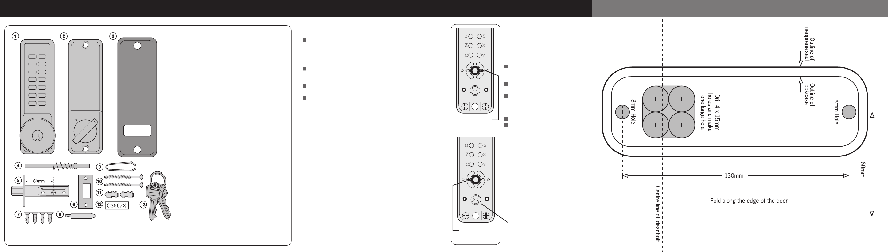
SPECIAL NOTESMortice Deadbolt CONTENTS 1. OUTSIDE KNOB LOCKING ACTION
T E M P L A T E
1. Front plate (key override option shown)
2. Back plate
3. Neoprene seals x 2
4. Spring loaded spindle
5. Deadbolt (60mm backset)
6. Keeper plate
7. Wood screws x 4
Use with deadbolt & keeper plate
8. Deadbolt support post
9. Tweezers (for changing the code)
10. Fixing bolts 3 supplied (spare x1)
11. Spare code tumblers x 2
12. Code card
13. 2 keys - key override models only
Tools required for installation
Power drill
25mm, 15mm & 8mm drill bits
Bradawl
Philips screwdriver size 2
Chisel (maximum 25mm)
Hammer/Mallet
Stanley knife
Adhesive tape
Pencil
Tape measure
You are advised to familiarise yourself with the
instructions before starting work.
Before commencing installation check that all parts are
working correctly – press the code according to the code
card and then the knob should turn and return easily under
spring pressure. If you have a key override lock try the keys
to ensure that they turn in the knob handle.
If you intend to change the code, you should do it, if it is
convenient, before installing the lock – see the code change
instructions in the separate leaflet.
Check that the deadbolt moves freely by turning the flat
spindle in the cam.
From outside the code is required both to lock and to
unlock the bolt. If you would like to be able to
LOCK your
door from outside WITHOUT using the code then follow
instruction 1.
Leave this pin
for left handed doors
NB – Your door is Right Handed
if, from outside, the hinges are
on the right.
To enable LOCKING of the bolt
from the outside WITHOUT
using the code:
Press the C button to reset the
chamber and place the lock case on
a flat surface with the buttons down.
Remove the code chamber plate held
in place with the two red screws.
With the tweezers remove the
right-hand pin for right handed
doors, or the left-hand pin for
left handed doors.
Replace the cover plate.
The outside knob will now feel
loose and turn freely in one
direction, and will require the code
to be used before it will turn in the
other direction.
Leave this pin
for right handed doors
NB When installing the lock make
sure that the driver is in the correct
position before installing the
spindle.
 Loading...