

Page 1
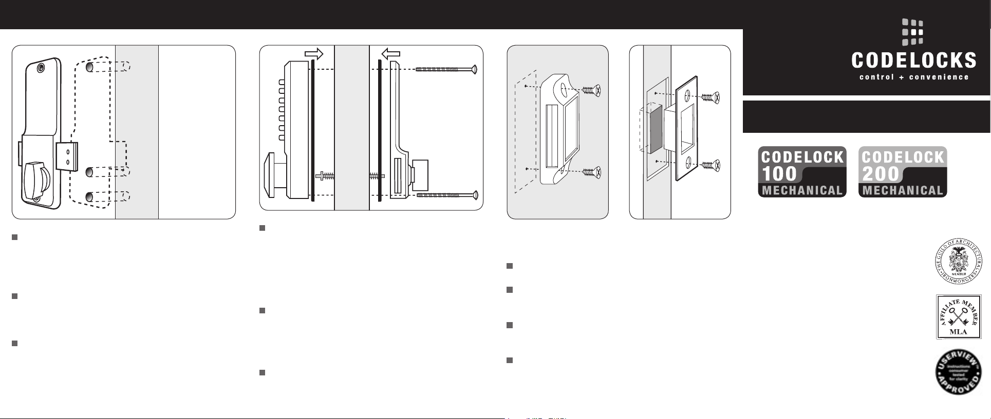
3. POSITIONING THE LOCK 4. FIXING THE LOCK 5. FITTING THE KEEPER
Note:
Establish which
keeper to use,
and mark its
position on the
frame, before
proceeding to
drill the door
for the lock
(see step 5).
Note:
Do not close the
door until you
are SURE that
the code works.
INSTALLATION INSTRUCTIONS
Remove the inside cover plate from the back plate, and
install the deadbolt according to the hand of your door.
Note that the standard bolt projects 40mm to the locking
side. A shorter bolt which projects 20mm is available.
Set the back plate with the knob in the vertical position and
hold it to the door with one end of the bolt against the frame
where the keeper will be fitted (see step 5).
Mark the position of the top fixing hole, and then using one
of the packing pieces as a template mark the position of the
lower fixing hole and the hole for the spindle.
Drill 8mm holes for fixing bolts and 13mm hole for spindle.
The spring loaded spindle will fit doors between 35mm and
65mm thick. For doors less than 50mm thick break off the
15mm section at the end of the spindle. For doors more
than 65mm thick ring the helpline for advice. The spring
keeps the spindle firmly engaged in the outside handle when
the lock is assembled on the door.
Cut the fixing bolts to suit the door thickness, allowing for
the rubber seals and at least one threaded section to screw
into the lock case.
Note that the bottom fixing bolt will be longer than the top.
Hold the lock case and the back plate, with the neoprene
seals in place, onto the door with the spindle in position.
Using the top fixing bolt first screw everything together.
Surface Keeper
fig. 5.1
First select the appropriate keeper for your frame.
Position the keeper on the frame so that it lines up with the
deadbolt and mark the appropriate holes.
If you are using the Surface Keeper simply screw into place
(see fig. 5.1). Use the packing pieces as required.
The Mortice Keeper will require cutting a small recess
(see fig. 5.2).
Mortice Keeper
fig. 5.2
Surface Deadbolts
& Key Override Versions
Helpline, service & spares
FREEPHONE 0800 393 405
CODELOCKS LTD
Tel 01635 239645
Fax 01635 239644
sales@codelocks.co.uk
www.codelocks.com
II-1/200SD-V02
Page 2
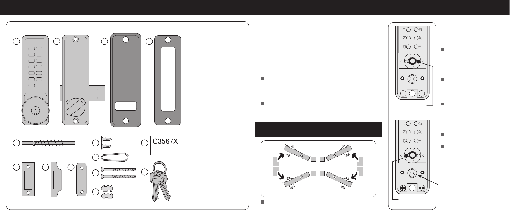
Use surface keeper
for inswinging
doors
Use
mortice
keeper for
outswinging doors
RIGHT HAND LEFT HAND
1
5
9
13
14
10
11
12
6
7
8
2
3
4
SPECIAL NOTESSurface Deadbolt CONTENTS 2. OUTSIDE KNOB LOCKING ACTION
Before commencing installation check that all parts are
working correctly. Press the code according to the code card
1. Front plate –
key override option shown
2. Back plate –
bolt is packed separately
3. Neoprene seals x2
4. Packing pieces x2
(for back plate only)
5. Spring loaded spindle
6. Mortice keeper
7. Surface keeper
8. Surface keeper
packing pieces x1
9. Wood screws x2
(to use with keeper)
10. Tweezers
11. Fixing bolts
3 supplied (spare x1)
12. Tumblers (spare x2)
13. Code card
14. 2 keys –
key override options only
Tools required for installation
Power drill
8mm & 13mm drill bits
Bradawl
Philips screw driver size 2
Chisel (maximum 15mm)
Hammer/Mallet
Stanley knife
Pencil
Tape measure
and the knob should then turn, in either direction, once only,
and return easily under spring pressure. From inside the door
the bolt can be freely locked and unlocked using the knob.
From outside the code is required both to lock and to unlock
the bolt. If you would like to be able to LOCK your door from
outside WITHOUT using the code then follow instruction 2.
If you intend to change the code then, if it is convenient, you
should do it before installing the lock. See the code change
instructions in the separate leaflet.
Note that the lock is supplied as standard with a bolt which
projects 40mm from the side of the lock. A shorter bolt
which projects 20mm is available.
1. CHECK THE HAND OF YOUR DOOR
Your door is right-handed if, viewed from outside, the hinges
are on the right.
Leave this pin
for left handed doors
Leave this pin
for right handed doors
To enable LOCKING of the
bolt from outside WITHOUT
using the code:
Press the C button to reset the
chamber and place the lock
case on a flat surface with the
buttons down.
Remove the code chamber
plate held in place with the two
red screws.
With the tweezers remove the
right-hand pin for right-handed
doors, or the left-hand pin for
left-handed doors.
Replace the cover plate.
The outside knob will now feel
loose and turn freely in one
direction, and will require the
code to be used before it will
turn in the other direction.
NB When installing the lock
make sure that the driver is in the
correct position before installing
the spindle.
 Loading...