

Page 1

CL300 Mortise Latchset Installation Instructions
Contents
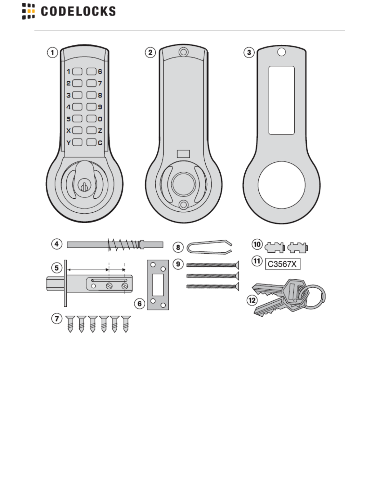
1 Front plate
2 Back plate
(hold-open models have a
sliding snib)
3 Gaskets x 2
4 Spring loaded spindle
5
Latch 2 / " (60mm) and 2 / "
3
8
3
4
(70mm) backset
6 Strike plate
7 Wood screws x 6
Use with latch & strike plate
8 Tweezers (for changing the
code)
9 Fixing bolts 3 supplied (spare
x1)
10 Code tumblers (spare x 2)
11 Code card
12 2 keys - key override models
only
Tools Required for installation:
• Power drill
1” (25mm), 21/8” (54mm) & 5/16” (8mm) drill bits
• Bradawl
• Phillips screwdriver size 2
• Chisel maximum 1” (25mm)
• Hammer/Mallet
• Tape measure
• Stanley knife
• Pencil
• Adhesive Tape
Find more online at www.codelockssupport.com
Page 1
Page 2
Find more online at www.codelockssupport.com
Page 2
Page 3
Find more online at www.codelockssupport.com
Special notes
You are advised to familiarise yourself with the instructions
before starting work.
• As standard locks are supplied as ‘hold open’ function with a snib
on the backplate. This enables the latchbolt to be held open when
required.
• When using the ‘hold open’ function please note that the backplate
is fitted with a blue screw to stop the handle moving in the wrong
direction. The screw should be in the left hand hole for a right hand
door or the right hand hole for a left hand door.
• To disable the ‘hold open’ see note 4. Disable Hold-Open
Function.
• Make sure that the knob of the backplate turns freely. If your lock is
a ‘hold-open’ model then check that the snib will engage and hold
the knob in the ‘latch-open’ position.
• Check that the latch bolt moves freely by pressing at the end and
also by turning the flat spindle in the latch cam.
1. CHECK THE HAND OF YOUR DOOR
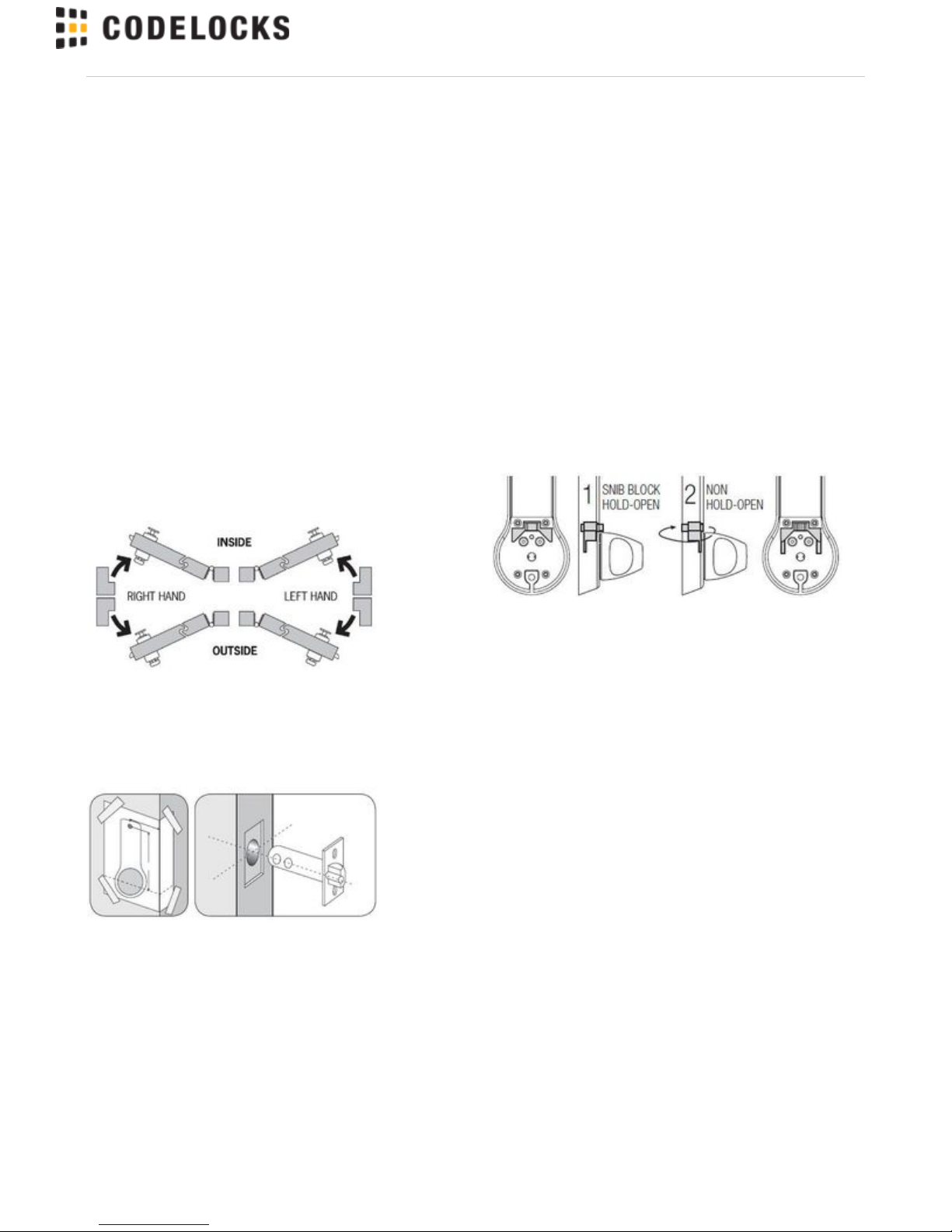
Viewed from outside, a door is right handed if the hinges are on the
right, and left handed if the hinges are on the left.
2. APPLY THE TEMPLATE
• Crease the template along the line marked Door Edge, and tape it
to the door.
• Mark the 2 1/8” (54mm) holes and the 3/8” (8mm) holes. Mark the
centre line of latch in the middle of the door edge. Now apply the
template to the other side of the door, aligning it with your first mark
in the middle of the door edge.
• Mark the 2 holes again. Keeping the drill level and square to the
door, drill holes from both sides to avoid splintering out of door face.
Positioning and fixing the latch
• Mark a central point on the ‘centre line of latch’ on the door edge.
• Mark the depth of 3 1/2” (90mm) on the drill bit with tape to act as a
visible depth limit. Drill a 1” (25mm) hole, 3 3/8” (90mm) deep,
keeping the drill level and square to the door.
• Insert the latch into the hole, and with the edges parallel to the
door, draw around the face plate.
• Remove the latch. Score the pencil line with a Stanley knife to
avoid splitting prior to chiselling. Chisel a 1/8” (3mm) rebate to fit the
latch face flush to the door edge.
• Fix the latch with the wood screws, with the bevel towards the door
frame.
3. DISABLE HOLD OPEN FUNCTION
• If required the hold open feature can be disabled as follows:
Remove fixing plate by removing the four fixing screws and blue
handing screw.
1. Lift out the snib block.
2. Flip over and reseat. Refit the fixing plate.
Do not fit the blue handing screw.
Page 3
Page 4
Find more online at www.codelockssupport.com
4. POSITIONING THE SPINDLE
• The spring-loaded spindle will fit doors between 1 / " - 2 / " (35m
3
8
1
2
m and 65mm) thick. For doors less than 2" (50mm) thick break off
the / " (15mm) section at the end of the spindle. For doors more
5
8
than 2 / " (65mm) thick, ring the Helpline for advice. The spring
1
2
keeps the spindle firmly engaged in the outside handle when the
lock is assembled on the door.
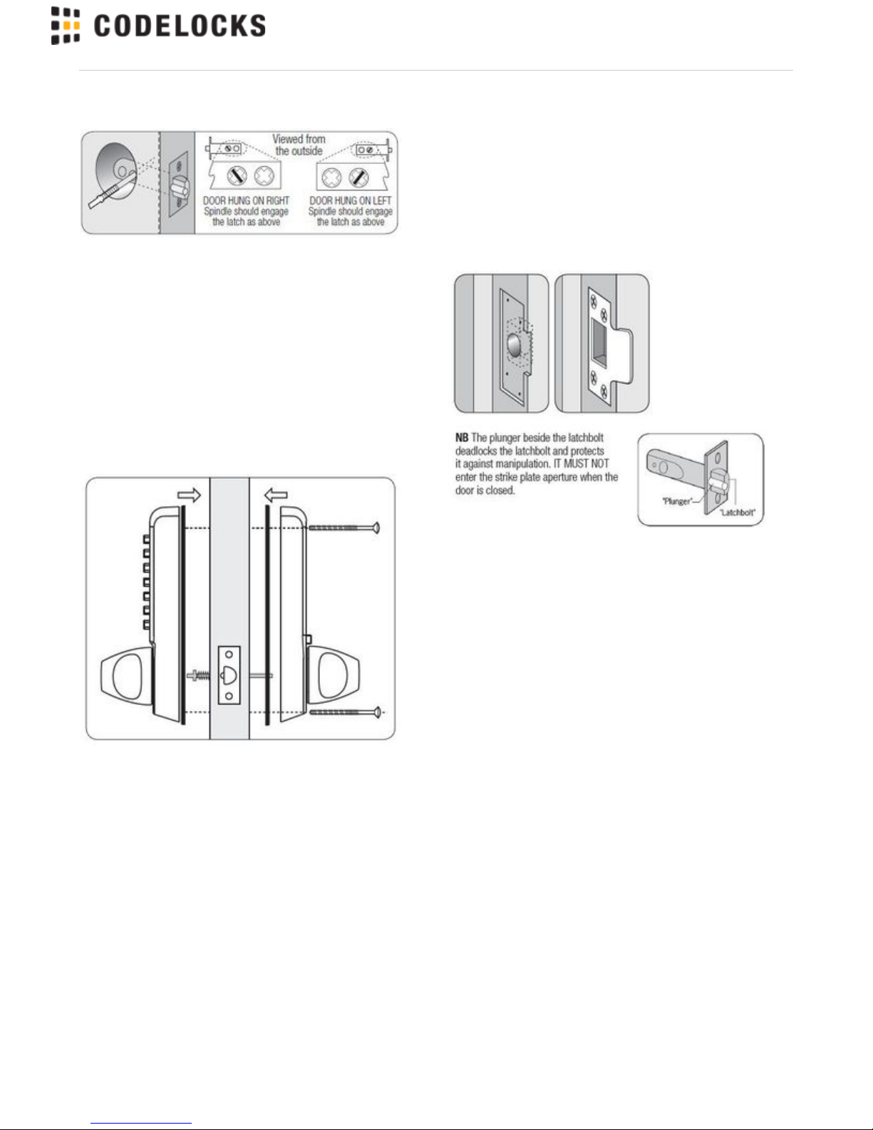
• Insert the spindle, with the spring on the code side, through the 2 /
1
" (54mm) hole in the door, and make sure that it engages the latch
8
correctly for the hand of the door (see inset diagram).
5. FIXING THE LOCK
• Cut the fixing bolts to suit the door thickness, allowing at least one
threaded section to screw into the lockcase.
• Hold the lock case and the back plate, with the seals, onto the door
with the spindle in position.
• Using the fixing bolts screw everything together through the top
and bottom holes of the backplate. Before final tightening make sure
that the lock is vertical, and test the mechanism to ensure that it is
all moving easily.
DO NOT CLOSE THE DOOR UNTIL YOU ARE SURE THAT THE
CODE WORKS
DO NOT over-tighten the fixing bolts as this may cause distortion
and lead to poor operation.
6. FITTING THE STRIKE PLATE
• Ensure that there are no obstructions to prevent the door closing
properly into its frame, such as litter trapped in the hinge side.
• Position the strike plate on the door frame so that it lines up with
the flat of the latchbolt, NOT THE PLUNGER.
• Draw around the aperture of the strike plate. Chisel out the
aperture / " (15mm) deep to receive the latchbolt. Fix the strike
5
8
plate to the surface of the frame with one screw only. Close the door
and ensure that the latch bolt enters the aperture easily, and is held
without too much ‘play’. When satisfied, draw around the final
position of the strike plate, remove it and cut a / " (1mm) rebate to
1
16
enable it to fit flush. Re-fix the strike plate with both screws.
CODELOCKS UK HEADQUARTERS
Tel: +44 (0) 1635 239645
Fax: +44 (0) 1635 239644
[email protected]
www.codelocks.com
Helpline, service & spares
Freephone: 0800 393 405
II-CL300ML-v
CODELOCKS INC US
Tel: +1 714 979 2900
Fax: +1 714 979 2902
[email protected]
www.codelocks.us
Helpline, service & spares
Toll free: 1.877.codelock
CODELOCKS (Australia) PTY LTD
Tel: +61 2 9882 1009
Fax: +61 2 9882 6030
[email protected]
www.codelocks.com.au
Helpline, service & spares
Toll free: 1800 052 131
Page 4
 Loading...