

Page 1
INTEGRATION GUIDE
CR8000 Decoded Scan Engine
INTEGRATION GUIDE VERSION: 10
RELEASE DATE: MARCH 2017
Configuration Guidewww.codecorp.com YouTube.com/codecorporation
Page 2

Code Reader™ 8000 Integration Guide
Copyright © 2012-2017 Code Corporation.
All Rights Reserved.
The software described in this manual may only be used in accordance with the terms of its license agreement.
No part of this publication may be reproduced in any form or by any means without written permission from Code. This includes electronic or mechanical
means such as photocopying or recording in information storage and retrieval systems.
NO WARRANTY. This technical documentation is provided AS-IS. Further, the documentation does not represent a commitment on the part of Code
Corporation. Code Corporation does not warrant that it is accurate, complete or error free. Any use of the technical documentation is at the risk of the user.
Code Corporation reserves the right to make changes in specifications and other information contained in this document without prior notice, and the reader
should in all cases consult Code Corporation to determine whether any such changes have been made. Code Corporation shall not be liable for technical or
editorial errors or omissions contained herein; nor for incidental or consequential damages resulting from the furnishing, performance, or
use of this material. Code Corporation does not assume any product liability arising out of or in connection with the application or use of any product
or application described herein.
NO LICENSE. No license is granted, either by implication, estoppel, or otherwise under any intellectual property rights of Code Corporation. Any use of
hardware, software and/or technology of Code Corporation is governed by its own agreement.
The following are trademarks or registered trademarks of Code Corporation:
CodeXML®, Maker, QuickMaker, CodeXML® Maker, CodeXML® Maker Pro, CodeXML® Router, CodeXML® Client SDK, CodeXML® Filter, HyperPage,
CodeTrack, GoCard, GoWeb, ShortCode, GoCode®, Code Router, QuickConnect Codes, Rule Runner®, Cortex, CortexRM, CortexMobile, Code, Code Reader,
CortexAG, Cortex Studio, CortexTools, Affinity®, and CortexDecoder.
All other product names mentioned in this manual may be trademarks of their respective companies and are hereby acknowledged.
The software and/or products of Code Corporation include inventions that are patented or that are the subject of patents pending. U.S. Patents:
6997387, 6957769, 7428981, 6619547, 6736320, 7392933, 7014113, 7240831, 7353999, 7519239, 7204417, 6942152, 7070091, 7097099, 7621453.
The Code reader software is based in part on the work of the Independent JPEG Group.
Code Corporation, 12393 S. Gateway Park Place, Suite 600, Draper UT 84020
www.codecorp.com
C005383_10 CR80XX Integration Guide
2
Page 3

Table of Contents
1 – CR8000 Introduction ...................................................................4
1.1 – Product Overview ............................................................4
1.2 – SKU Descriptions ............................................................4
2 – Mechanical Specifications ...........................................................5
2.1 – Decoded Scan Engine Components .................................5
2.2 – Decoded Scan Engine with Mounting
Bracket Components ......................................................5
2.3 – Scan Engine Components ................................................6
2.4 – Scan Engine with Mounting Tabs Components ................. 6
2.5 – Scan Engine Mechanical Specifications ...........................6
2.6 – Scan Engine with Mounting Tabs
Mechanical Specifications ...............................................7
2.7 – Decode PCB Mechanical Specifications ...........................7
2.8 – CR8000 Decoded Scan Engine with
Bracket Specifications .....................................................8
2.9 – Enclosure Specifications ..................................................9
3 – Optical Considerations .................................................................10
3.1 – Window Requirements .....................................................10
3.2 – Imager Field of View ........................................................11
4 – Electrical Specifications ...............................................................12
4.1 – System Requirements ......................................................12
4.2 – Electrical System Block Diagram ......................................12
4.3 – Host Interface Pinouts (CR8012 RS232) ..........................13
4.4 – Host Interface Pinouts (CR8011 USB) .............................13
4.5 – Host Interface Pinouts (CR8013 micro-USB) ...................13
4.6 – Electrical Control Signals
(CR8011 and CR8012 only) ............................................14
4.7 – Power Modes (CR8011 and CR8012 only) .......................14
4.8 – Power On (Boot) Timing Diagram
(CR8011 and CR8012 only) ............................................15
4.9 – Power Down Timing Diagram ........................................... 16
4.10 – Sleep to Wakeup Timing Diagram ...................................16
4.11 – Image Capture and Decode Timing Diagram .................. 17
4.12 – Flex Cable Diagram (Imager Board to Decoder
Board on All Models) ....................................................17
4.13 – Ribbon Cable Diagram (Decode board to Host
Interface on CR8011 and CR8012) ...............................18
4.14 – Electrical Characteristics
(DC) – Absolute Ratings (Min and Max) .........................19
4.15 – Electrical Characteristics
(DC) – Operating Conditions ..........................................19
4.16 – Decode PCB to Scan Engine PCB Connector .................20
4.17 – Decode PCB Expanded Illumination Connector ..............21
5 – Configuration ...............................................................................22
5.1 – Serial Commands ............................................................22
6 – Shipping Specifications ...............................................................23
7 – General Specifications .................................................................24
8 – Reading Range Specifications .....................................................25
9 – Warranty .....................................................................................26
10 – APPENDIX A: Development Kit User Guide ................................27
10.1 – CR8000 Development Board .........................................27
10.2 – Development Board Connections ...................................28
10.3 – Development Board Jumpers .........................................29
10.4 – Development Board Fuses .............................................30
11 – APPENDIX B: Optimizing for Low Power Applications .................31
11.1 – Configuration .................................................................32
11.2 – Communications from Sleep Mode ................................32
11.3 – Timing Specifications ..................................................... 33
C005383_10 CR80XX Integration Guide
3
Page 4
1 – CR8000 Introduction
1.1 – Product Overview
The Code Reader™ 8000 (CR8000) is a patented, high performance,
miniature barcode imaging engine. The CR8000 continues Code’s legacy
of dual optical fields - while most devices have a single field enhanced for
a specific application, the CR8000 has both a high density field for reading
the smallest of barcodes, and a wide angle field for reading oversized
barcodes giving you two readers in one.
The CR8000 includes Code’s Glare Reduction Technology. Barcodes printed
on shiny or reflective surfaces have typically been problematic for imagingbased barcode readers. Code has overcome this challenge with a patented
process that significantly reduces the reflections, thus making the barcodes
easily identifiable. In addition, the CR8000 supports the integration and
control of additional illumination blocks or elements. Example applications
that benefit from the expanded illumination are document scanning and
direct part marking.
For mechanical integration, a variety of mounting options are available
including tabs, blind through-holes, and mounting brackets for both the
Scan Engine and the decode board. The CR8000 communicates via RS232
or USB protocols.
Applications for the CR8000 include Medical Devices, ATMs, Price-Lookup,
Lottery, Age Verification, Direct Part Marking, Point of Sale, Self-Service
Kiosks and more.
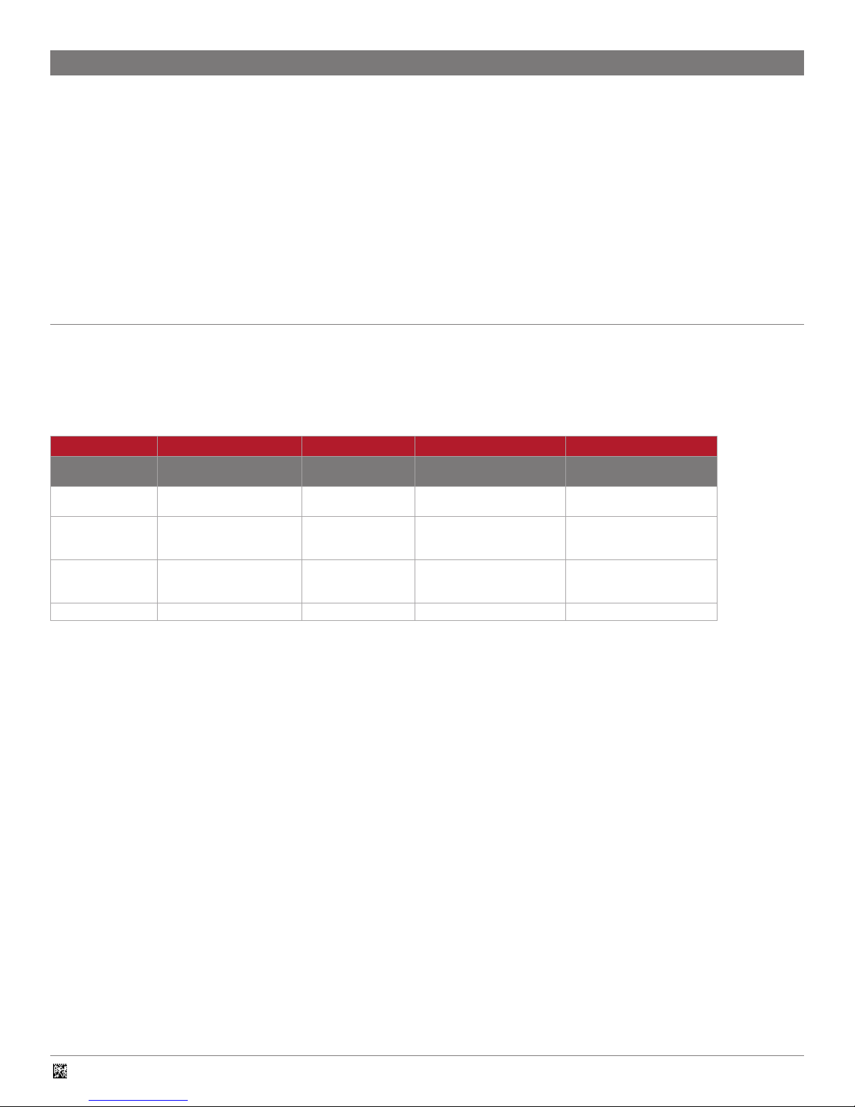
1.2 – SKU Descriptions
The following table describes the options available for the CR8000
Scan Engine. Any SKU (Part Number) can be built using the following table:
SKU: CR8### - L## - MT## - D## - C###
CR801# L## MT# D# C###
Communications
Interface
1 = USB
(Ribbon Cable)
2 = RS232
(Ribbon Cable)
3 = USB
(micro-USB Cable)
Wide Field/High
Density Field Focus
00 = Standard Focus
WF: 115 mm; HD: 110 mm
Mounting Options Flex Cable
X = No Tabs
or Brackets
1= With Tabs;
No Bracket
(see Section 2.1)
2 = With Tabs and
Standard Bracket
(see Section 2.2)
X = No Flex Cable X = No Ribbon Cable
0 = Standard Flex Cable 800 = 2.0" Ribbon Cable
1 = Reverse Flex Cable
(for Bracket Mount)
2 = In-Line Flex Cable 802 = 12.0" Ribbon Cable
801 = 6.0" Ribbon Cable
Ribbon Cable
(CR8011/CR8012 only)
EXAMPLE: CR8000 USB with Standard Focus,Tabs,
Standard Flex, 2.0" Ribbon Cable.
SKU = CR8011-L00-MT1-D0-C800
Note: Additional Ribbon Cables, Flex Cables, and Focus options may
be available for your application. Please contact your Code representative
to discuss.
C005383_10 CR80XX Integration Guide
4
Page 5
2 - Mechanical Specifications
The CR8000 is offered in multiple mechanical configurations. It can be
ordered as either an assembly or unassembled with or without Scan Engine
mounting tabs.
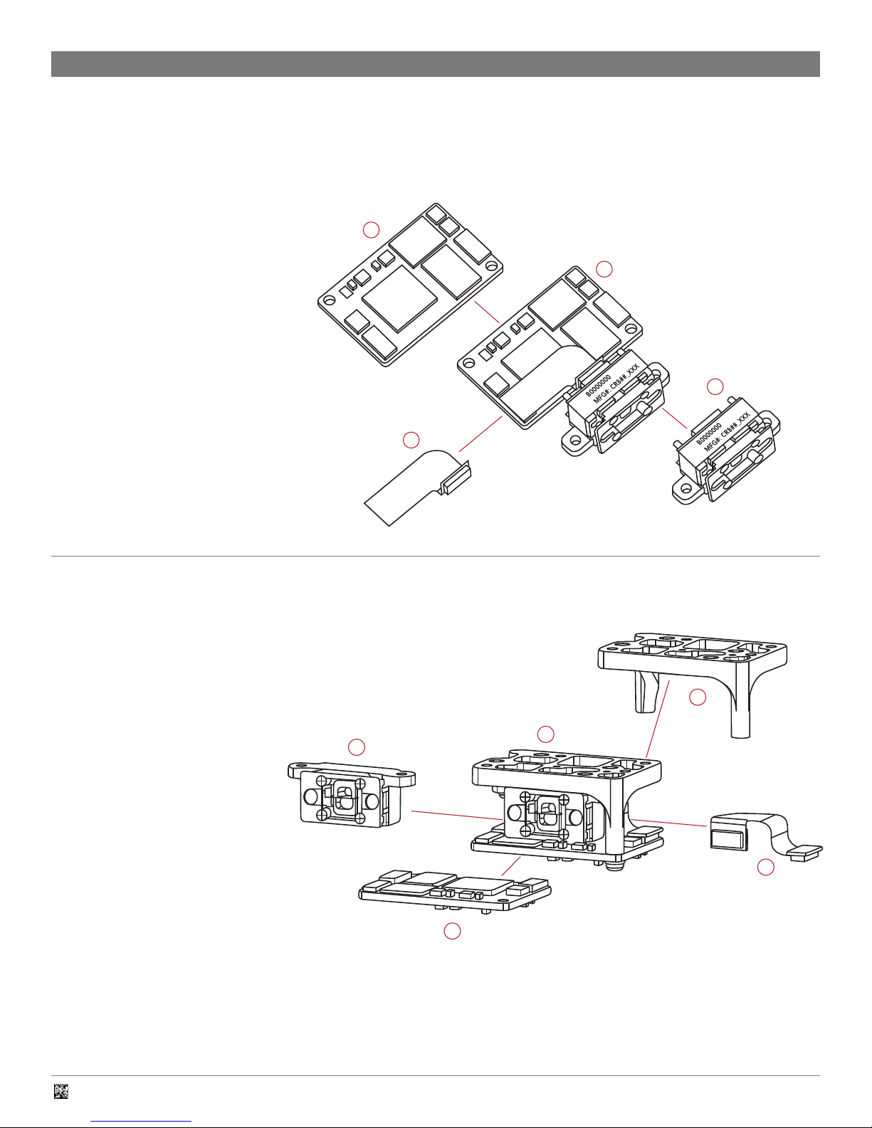
2.1 – Decoded Scan Engine Components
Fully Assembled Unit
1. CR8000 Decoded Scan Engine
3
Individual Components
2. Scan Engine (shown with tabs)
3. Decode Board
4. Decode Board to Scan Engine Flex Cable
(shown with Standard Flex Cable)
4
2.2 – Decoded Scan Engine with Mounting Bracket Components
Fully Assembled Unit
1. CR8000 Decoded Scan Engine
with Mounting Bracket
1
2
Individual Components
2. Scan Engine
3. Mounting Bracket (has multiple
possible configurations)
4. Decode Board
5. Decode Board to Scan Engine Flex
Cable (shown with Reverse Flex Cable)
C005383_10 CR80XX Integration Guide
3
1
2
5
4
5
Page 6
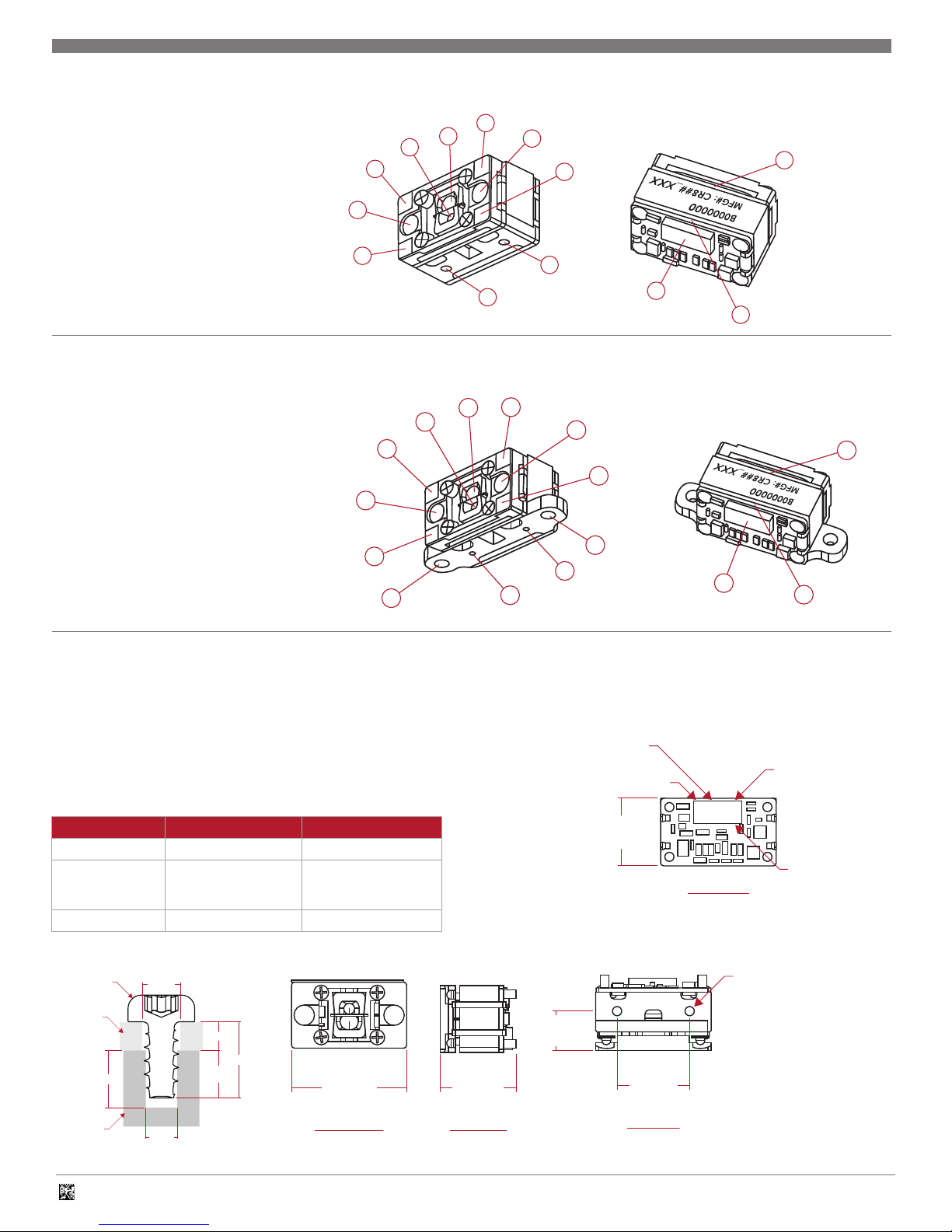
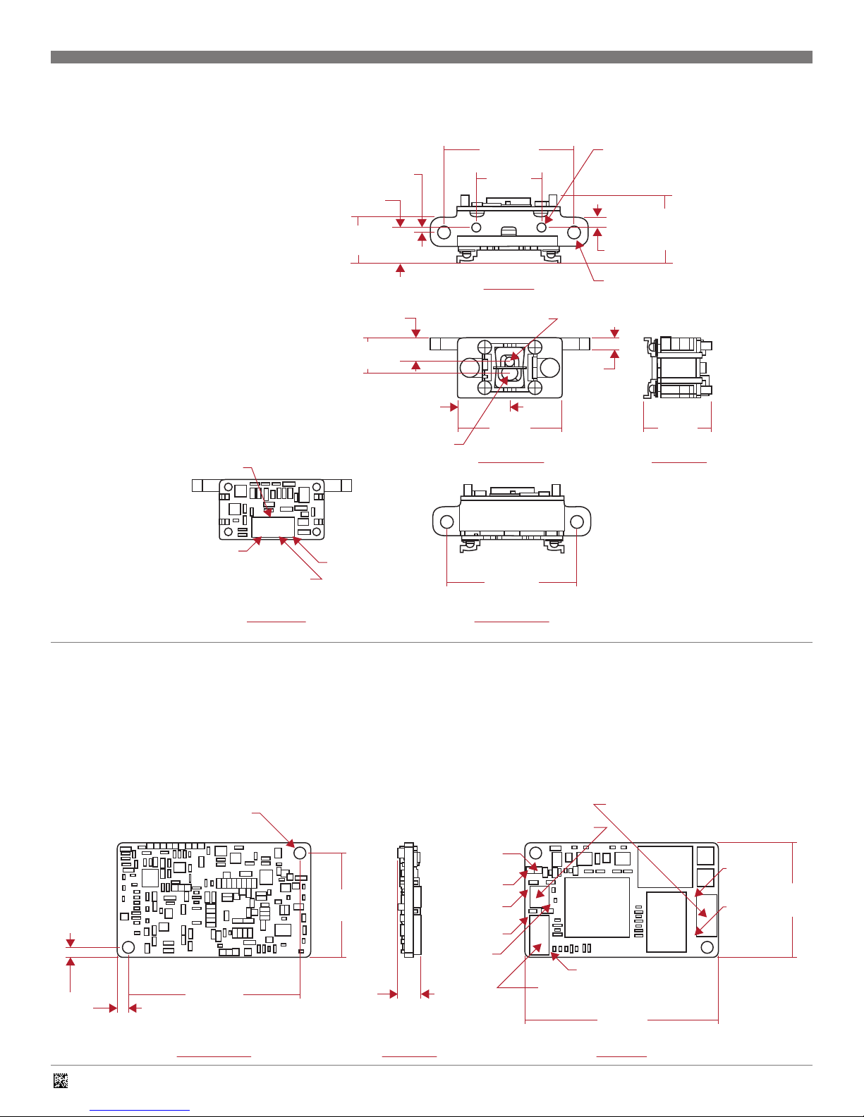
2.3 – Scan Engine Components
13.53
[.532]
SIDE VIEW
7.12
[.280]
13.00
[.512]
Ø1.65 [.065] X 3.00 [.128]
2 PLACES - HOLES ARE
PROVIDED FOR MOUNTING
WITH SELF-TAPPING SCREWS
TOP VIEW
11.90
[.468]
PIN 29
PIN 30
PIN 2
HIROSE CONNECTOR
P/N: DF40C-30DS-0.4V(51)
BACK VIEW
UNITS = MM [INCHES]
7.12
[.280]
13.00
[.512]
Ø1.65 [.065] X 3.00 [.128]
2 PLACES - HOLES ARE
PROVIDED FOR MOUNTING
WITH SELF-TAPPING SCREWS
TOP VIEW
11.90
[.468]
PIN 29
PIN 30
PIN 2
HIROSE CONNECTOR
P/N: DF40C-30DS-0.4V(51)
BACK VIEW
UNITS = MM [INCHES]
WITH SELF-TAPPING SCREWS
11.90
[.468]
PIN 29
PIN 30
PIN 2
BACK VIEW
2
1. Blue LED Targeting Lens
2. Red LED Illumination Lens
4
3
2
1
3. High Density Field Lens
4. Wide Field Lens
1
5. Self-Tapping Screw Holes
6. Printed Circuit Boards
2
7. Connector, Receptacle, 30 pin,
0.4 mm pitch
5
2.4 – Scan Engine with Mounting Tabs Components
2
1. Blue LED Targeting Lens
2. Red LED Illumination Lens
3. High Density Field Lens
4. Wide Field Lens
5. Mounting Tabs
6. Self-Tapping Screw Holes
7. Printed Circuit Boards
8. Connector, Receptacle, 30 pin,
0.4 mm pitch
2
1
2
5
4
3
6
2
6
5
7
6
1
7
2
5
6
8
7
2.5 – Scan Engine Mechanical Specifications
1. The Scan Engine has two holes available for
mounting with 2 self-tapping screws.
2. Please use #1-32 Trilobular® thread
forming screw or M1.8 Delta PT®
thread forming screw, with the following
dimensions:
Mininum Maximum
Thread Engagement 2.00 mm 2.50 mm
Length (B)
Torque N/A 1.5 Ibf-in
#1-32 OR
M1.8 SCREW
MOUNTING
SUBSTRATE
C8200 HOUSING
CR8000
(3.00)
Mounting Substrate
Thickness (A) + 2.00 mm
(Ø2.00)
(Ø1.65)
A
2.50 MAX
2.00 MIN
B
Mounting Substrate
Thickness (A) + 2.50 mm
20.58
[.810]
FRONT VIEW
13.53
[.532]
SIDE VIEW
HIROSE CONNECTOR
P/N: DF40C-30DS-0.4V(51)
11.90
[.468]
7.12
[.280]
TOP VIEW
PIN 2
PIN 30
PIN 29
BACK VIEW
Ø1.65 [.065] X 3.00 [.128]
2 PLACES - HOLES ARE
PROVIDED FOR MOUNTING
13.00
[.512]
UNITS = MM [INCHES]
C005383_10 CR80XX Integration Guide
6
Page 7
2.6 – Scan Engine with Mounting Tabs Mechanical Specifications
1. The CR8000 with Mounting Tabs has two
tabs with mounting holes as well as two
blind holes available for mounting with 2
self-tapping screws.
2. For the Mounting Tabs, please use M2.2
x 6 Phillips pan head screws. The design
does not require a washer, however, if one
is desired, Code recommends a flat washer,
No. 2 Screw Size, .19" OD,
.01"-.03" thick.
3. For the Blind Holes, please use M2.2 x 4.5
Phillips pan head, type AB, steel, zinc clear,
Trivalent self-tapping screws.
PIN 29
1.00
[.039]
7.12
[.280]
9.16
[.361]
4.75
[.187]
7.15
[.281]
[.405]
C
OF OPTICAL PATH
L
10.29
26.00
[1.024]
13.00
[.512]
TOP VIEW
C
OF OPTICAL PATH
L
20.58
[.810]
FRONT VIEW
E0000000
MFG#: CR8##_XXX
Ø1.65 [.065] X 3.00 [.128] 2 PLACES
HOLES ARE PROVIDED FOR MOUNTING
WITH SELF-TAPPING SCREWS.
13.53
[.532]
2.04
[.080]
CLEARANCE HOLE FOR
#2 OR M2 SCREW (2 PLACES)
2.45
[.096]
13.53
[.532]
SIDE VIEW
PIN 30
HIROSE CONNECTOR
P/N: DF40C-30DS-0.4V(51)
BACK VIEW
PIN 2
2.7 – Decode PCB Mechanical Specifications
1. The CR8000 Decode PCB has two holes available for mounting.
2. Please use M2.2 Phillips pan head screws with flat nylon washers, No.
2 Screw Size, 0.19" OD, 0.02" thick.
CR8011 and CR8012
2.54 [.100] CLEARANCE HOLE
2.25
[.089]
2 PLACES
34.50
[1.358]
HIROSE DF40C-10DS-0.4V(51)
22.75
[.896]
7.30
[.287]
[1.024]
BOTTOM VIEW
TP29
TP28
PIN 1
PIN 1
PIN 10
26.00
CONNECTOR FPC ZIF
P/N: FCI 10051922-1210ELF
PIN 30
HIROSE CONNECTOR
P/N: DF40C-30DS-0.4V(51)
39.00
[1.535]
UNITS = MM [INCHES]
PIN 12
PIN 1
25.00
[.984]
BOTTOM VIEW UNITS = MM [INCHES]
C005383_10 CR80XX Integration Guide
SIDE VIEW
TOP VIEW
7
Page 8
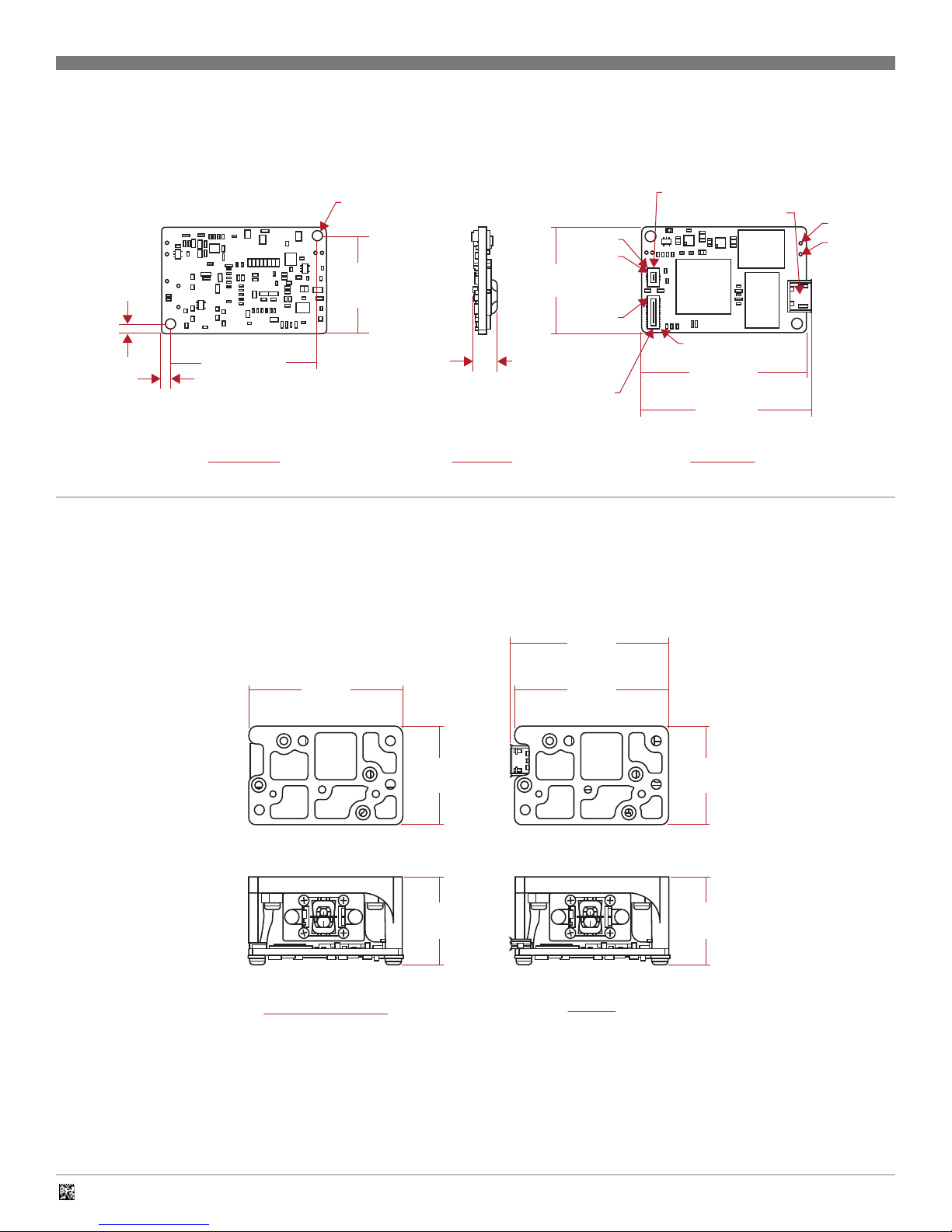
2.7 – Decode PCB Mechanical Specifications (continued)
CR8013
2.54 [.100]
CLEARANCE HOLE
2PLACES
PIN 1
PIN 10
25.00
[.984]
PIN 1
2.25
[.089]
2.25
[.089]
34.50
[1.358]
FRONT VIEW
22.75
[.896]
5.65
[.222]
HIROSE CONNECTOR
P/N: DF40C-30DS-0.4V(51)
SIDE VIEW
2.8 – CR8000 Decoded Scan Engine with Bracket Specifications
The CR8000 bracket has six holes for mounting the device: two unthreaded
holes and four threaded holes. This allows the use of
both self-tapping and machine screws in the target application.
Overall Dimensions
40.13
[1.580]
HIROSE DF40C-10DS-0.4V(51)
MICRO USB TYPE B
PIN 30
39.00
[1.535]
40.13
[1.580]
BACK VIEW
UNITS = MM [INCHES]
TP 31
TP 32
39.00
[1.540]
CR8011 and CR8012
25.00
[.980]
21.83
[.860]
39.00
[1.540]
25.00
[.980]
21.83
[.860]
CR8013
C005383_10 CR80XX Integration Guide
8
Page 9
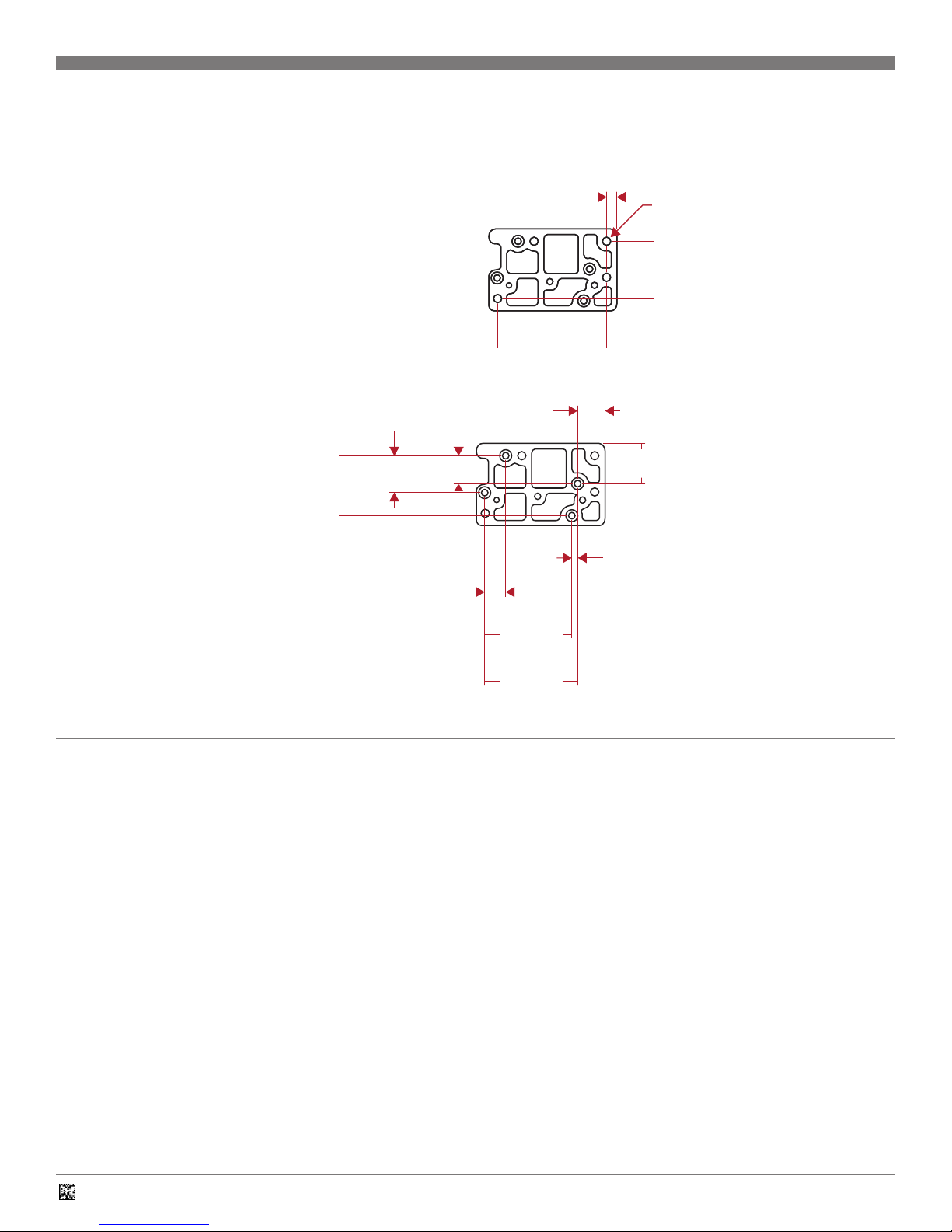
2.8 – CR8000 Decoded Scan Engine with Bracket Specifications (continued)
Non-Threaded Mounting Holes
There are two 2.50 mm diameter non-threaded
mounting holes on the CR8000 bracket,
shown below.
3.24
3.24
[.128]
[.128]
33.09
33.09
[1.303]
[1.303]
2X 2.50 [.098]
2X 2.50 [.098]
± .07 THRU
± .07 THRU
17.35
17.35
[.680]
[.680]
Threaded Mounting Holes
There are four M2 threaded mounting holes
on the CR8000 bracket, shown below. We
recommend using a M2X5 machine screw
for mounting.
18.24
[.720]
11.23
[.440]
2.9 – Enclosure Specifications
1. The enclosure for the CR8000 should be sufficiently large enough
to accommodate the engine and allow air flow to maintain safe
temperatures. The enclosure should minimize infiltration by
airborne contaminants and foreign materials.
2. The CR8000 must not come in contact with water.
[.330]
6.27
[.250]
8.44
8.42
[.330]
12.22
[.480]
1.85
[.070]
26.24
[1.030]
28.09
[1.110]
3. The CR8000 is sensitive to Electrostatic Discharge (ESD) and must be
handled appropriately. Any individual that handles the CR8000 should
be grounded using a wrist strap and ESD protected work area and
work surface.
4. The warranty of the CR8000 is void if the recommendations above are
not followed when handling or integrating the device.
UNITS = MM [INCHES]
C005383_10 CR80XX Integration Guide
9
Page 10
3 - Optical Considerations
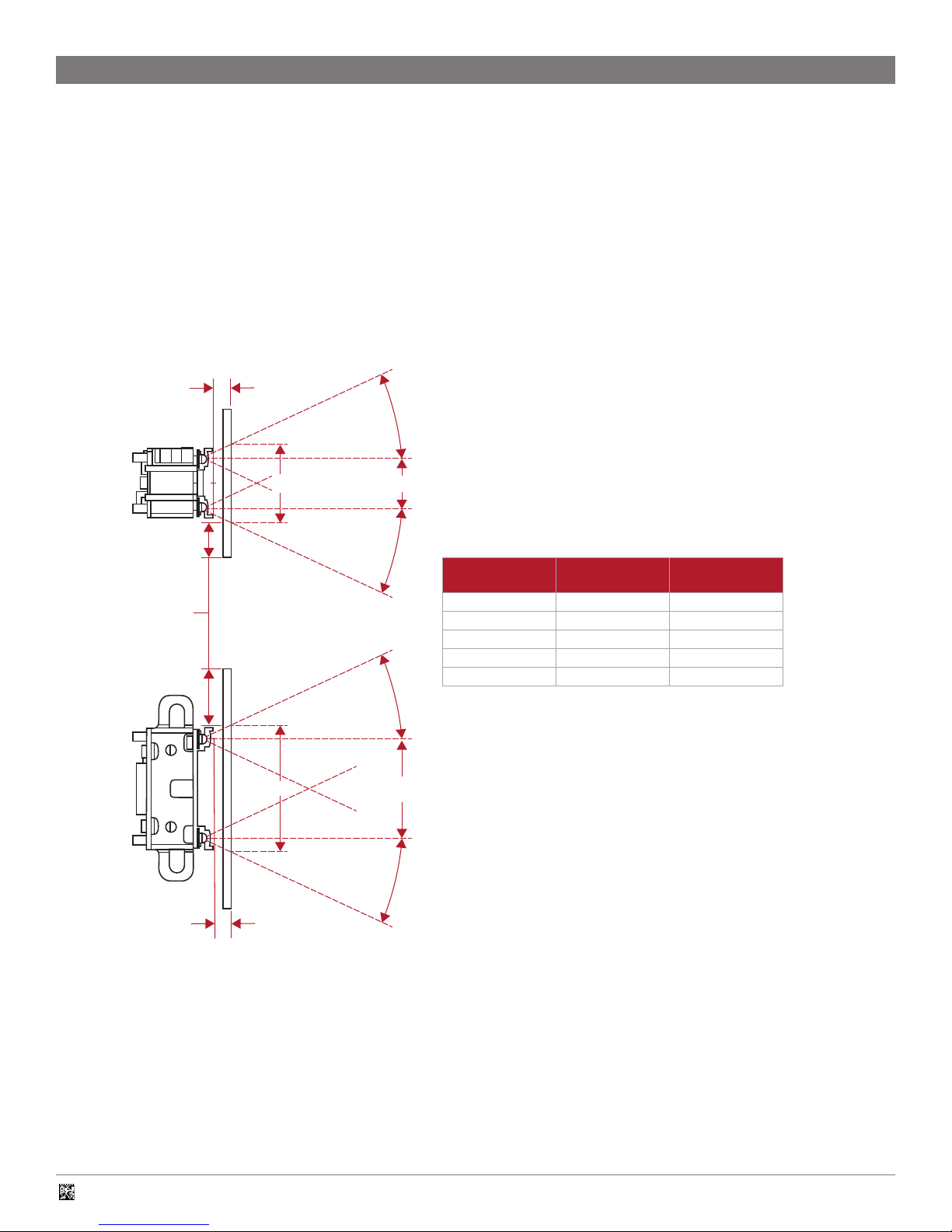
3.1 – Window Requirements
When integrating the CR8000 into your device or application, it may be
necessary to install a window in front of the optics of the Scan Engine.
Although many different types of materials can be considered, Code makes
the following recommendations.
Placement: Contact to 0.5 mm away from the face of the Scan Engine,
parallel to engine face
Material: Optically clear acrylic
Thickness: 1 mm or less
CR8000 Field of Illumination Diagram
D
25.00˚
H
WINDOW SIZE MUST
EXCEED WIDTH
AND HEIGHT OF
ILLUMINATION ANGLE
8.69 (CENTER-TO-CENTER LED SPACING)
25.00˚
25.00˚
If your design constraints prevent the window from being mounted within
0.5 mm of the face of the engine, Code recommends an anti-reflective
(AR) coating be applied to both window surfaces (front and back). The AR
coating must have less than 3% reflectance from 400nm to 1000nm.
The window must be wide and tall enough so the surrounding enclosure
does not block any of the illumination from the LEDs. The following diagram
illustrates the field of illumination that must be unobstructed
by the edges of the window aperture.
Distance to
Window (D)
1 mm 19.58 mm 11.40 mm
2 mm 20.51 mm 12.33 mm
3 mm 21.44 mm 13.26 mm
4 mm 22.37 mm 14.20 mm
5 mm 23.31 mm 15.13 mm
*Window must exceed this width/height
Illumination
Width (W)*
Illumination
Height (H)*
W
D
C005383_10 CR80XX Integration Guide
16.87 (CENTER-TO-CENTER LED SPACING)
25.00˚
10
Page 11

3.2 – Imager Field of View
The CR8000 Decoded Scan Engine contains an imager with both Wide
Angle and High Density Fields. The Field of View for both Wide Angle
and High Density optics is shown below for Horizontal and Vertical
positioning of the imager:
CR8000 Field of View Diagram
HIGH DENSITY FOV
WIDE FIELD FOV
HIGH DENSITY FOV
16.75 ˚
16.75 ˚
15.00 ˚
10.00 ˚
10.00 ˚
25.00 ˚
WF
WIDE FIELD FOV
C005383_10 CR80XX Integration Guide
15.00 ˚
25.00 ˚
11
Page 12

4 - Electrical Specifications
4.1 – System Requirements
Power Supply: The CR8000 is powered from the host via the Vin and Gnd
pins. Vin must be within the range specified in Section 4.15 when measured
at the decoding board. Vin must be maintained with varying loads, such as
when the illumination is turned ON and OFF.
Host Ribbon Cable (FFC) (CR8011 and CR8012): The impedance of
the cable for the USB data lines should be 90 ohm differential. For 3.3V
operation, a Ribbon Cable of no more than 6.0" in length can be used with a
0.28 mm (0.011") trace width and 0.3 mm trace thickness.
Scan Engine to Decode Board Flex Cable (FPC): When leveraging a
non-bracketed design, care should be taken to alleviate bend stress on the
Flex Cable, which could lead to damage of that cable. The minimum bend
radius for this cable is 2.0 mm. Drawings can be provided upon request to
aid in design. Flex Cable length should not exceed 6.0".
4.2 – Electrical System Block Diagram
The CR8000 Decoded Scan Engine is a complete barcode scanning
system that can be easily integrated into any device.
The block diagram below shows the main components of the system
(CR8011/8012).
RIBBON CABLE (RS232/USB)
Power Sequencing: There is no special power sequence needed for the
CR8000 as long as the max and min voltage and current specifications are
met. However, if the voltage on a pin is greater than Vin, such as
when powering on, then current will flow from the pin to Vin through
the pull up resistors.
Thermal Requirements: The operating temperature range for the CR8000 is
-20ºC to 55 ºC (-4ºF to 131ºF) ambient air.
RS232 Polarit/NU
V
IN
GND
RXD/USB D-
TXD/NU
CTS/USB D+
RTS/NU
PwrDwn
nBeeper
nGoodRead
nWakeUp
nTrigger
NU = Not Used on USB Model
DECODE
PCBA
FLEX CABLE
Power
Illum. Control
I2C Bus
Image Control
Image Data
OPTICAL
ENGINE
C005383_10 CR80XX Integration Guide
12
Page 13

4.3 – Host Interface Pinouts (CR8012 RS232)
Pin Name Type Description Note
1 RS232 Polarity Input RS232 polarity control. When high, all RS232 signals have their normal polarity.
When low, all RS232 signals have inverted polarity.
2 Vin Power Power supply voltage input
3 Gnd Power Power supply and signal ground
4 RxD Input RS232 receive data, TTL level 1
5 TxD Output RS232 transmit data, TTL level 1
6 CTS Input RS232 Clear to Send, TTL level 1
7 RTS Output RS232 Request to Send, TTL level 1
8 PwrDwn Output Power down indicator; active high 1
9 nBeeper Output Feedback indicator (success, error, etc.); active low 1
10 nGoodRead Output Indicates a successful decode; active low 1
11 nWakeUp Input Bring the unit out of sleep state; active low 1,2
12 nTrigger Input Activate image acquisition, decode; active low 1
Notes: 1. Pin has a weak pull up to Vin.
2. If not actively controlling sleep mode, leave unconnected. Do not tie low.
4.4 – Host Interface Pinouts (CR8011 USB)
Pin Name Type Description Note
1 <unused> Input 1
2 Vin Power Power supply voltage input
3 Gnd Power Power supply and signal ground
4 D- Bidirectional USB D- signal
5 <unused> Output 1
6 D+ Bidirectional USB D+ signal
7 <unused> Output 1
8 PwrDwn Output Power down indicator; active high 1
9 nBeeper Output Feedback indicator (success, error, etc.); active low 1
10 nGoodRead Output Indicates a successful decode; active low 1
11 nWakeUp Input Bring the unit out of sleep state; active low 1,2
12 nTrigger Input Activate image acquisition, decode; active low 1
1
Notes: 1. Pin has a weak pull up to Vin.
2. If not actively controlling sleep mode, leave unconnected. Do not tie low.
4.5 – Host Interface Pinouts (CR8013 micro-USB)
Pin Name Type Description Note
1 Vin Power +5 VDC
2 D- Bidirectional USB D- signal
3 D+ Bidirectional USB D+ signal
4 ID Output On-the-GO (OTG) Host/Device ID 1
5 Gnd Power Power supply and signal ground
Notes: 1. Not supported.
C005383_10 CR80XX Integration Guide
13
Page 14

4.6 – Electrical Control Signals (CR8011 and CR8012 only)
The CR8000 is equipped with inputs and outputs that allow the user to
control the reader and get certain status information via hardware signals. A
brief description of each signal is given in this Section. For additional details
on the interaction and timing of these signals, refer to the Timing Diagrams
and Tables in the Sections that follow. To get more information on register
functions, refer to the Interface Configuration Document (ICD), available on
the Code website (www.codecorp.com).
Pin 8 - Power Down (output): The PwrDwn line is used to indicate the
operational state of the reader. PwrDwn will be asserted HIGH when the
CR8000 has switched to the sleep state. PwrDwn will transition back to the
LOW state when the CR8000 is not in the sleep state. The different power
modes are described in more detail in the Section 4.7.
Pin 9 – Beeper (output): The nBeeper line is used to indicate a successful
decode, completion of the boot process, errors, and certain other conditions
or events. nBeeper can be configured to transition to a LOW state for a
specified length of time or to output a series of pulses of a specified duration
on a successful decode or on certain error conditions. The duration of
this signal can be set with register 0x59. Default behavior for this signal is
one “beep” for a good decode, two “beeps” for a successful configuration
barcode read, and four beeps if a configuration was not applied successfully.
Pin 10 - Good Read (output): The nGoodRead line is used to indicate
a successful decode. Upon the completion of a successful scan and
decode, the nGoodRead line will be asserted LOW. The length of
nGoodRead assertion can be set with register 0x1EA.
Pin 11 – Wakeup (input): The nWakeUp line is used to change the state
of the reader from Sleep to Idle. Once the CR8000 has entered the sleep
state, it may be awakened by asserting nWakeUp with a LOW pulse. Note
that nWakeUp must be HIGH when the CR8000 enters the sleep state in
order for nWakeUp to awaken the CR8000 on assertion. Also note that when
the sleep state is not being used, this pin should be left open, not tied low.
Please note that the Sleep state is only valid for CR8012.
Pin 12 – Trigger (input): The nTrigger line is used to activate the reader.
To activate the CR8000, pull the nTrigger line LOW. This is normally used to
cause the reader to scan for a barcode.
Note: All output signals except USB D- and USB D+ are connected to
open drain buffers with a pull-up of 100 Kilo-ohm to Vin and a maximum
current capability of 50 mA. All input signals except USB D- and USB D+
are connected to a pull-up to Vin and to a buffer with a 50 mA maximum
current capability.
Note: When Vin is initially supplied, PwrDwn and the other outputs will
be LOW for a few milliseconds until the voltages on the board come up.
They will then transition to default HIGH due to pull-ups until the unit
is up and running. These signals should be ignored until the unit is fully
functioning. See startup timing diagram below for details.
4.7 – Power Modes (CR8011 and CR8012 only)
Boot Mode: The CR8000 enters boot mode upon application of Vin. The
PwrDwn pin will be HIGH (after power on delay) until the main app starts.
Active Mode: In Active Mode the unit is capturing images and initiating the
decode process and/or storing images. The unit transitions to Active Mode
from Idle Mode when a trigger event is received.
Idle Mode: In Idle Mode the unit is not actively capturing images. The
processor is fully functioning and communication can take place, upgrades
can be performed, and scripts can be run. Idle Mode is entered from Boot
Mode after power on, from Active Mode after a register defined timeout in
which there are no trigger events, and from Sleep Mode on receipt of a wake
up.
Sleep Mode (CR8012 only): The imager, illumination, and most of the
processor is powered down. The CPU wake up circuitry, the memory, and
the input/output buffers are powered. The unit enters the sleep state after
a register defined timeout of inactivity, which is defined in register 0x9F. On
receipt of a wake up on the nWakeUp pin, the processor restores the run
environment and enters Idle Mode.
C005383_10 CR80XX Integration Guide
14
Page 15

4.8 – Power On (Boot) Timing Diagram (CR8011 and CR8012 only)
The PwrDwn signal will transistion to HIGH
shortly after Vin is applied and will remain HIGH
until the main application starts.
VIN
nBeeper
nGoodRead
PwrDwn
TPU1 TPU3
TPU2
Parameter Symbol Min Typical Max Unit Note
Time from Power On to
Outputs as Default
Time from Power On to
PwrDwn transition to LOW
Time from end of TPU2 to
reader in Idle Mode
Notes: 1. This time can be longer on USB model due to USB enumeration time.
TPU1 10 msec
TPU2 9000 msec
TPU3 1000 msec 1
C005383_10 CR80XX Integration Guide
15
Page 16

4.9 – Power Down Timing Diagram
Power (Vin) can be removed at any time except
when the unit is performing an upgrade.
Removing power during an upgrade may
cause the unit to become unusable.
Outputs
Parameter Symbol Min Typical Max Unit Note
Time from Power Off to
all outputs low
5V
VIN
0V
5V
0V
TPD1
Outputs: PwrDwn, nGoodRead, nBeeper
TPD1 56 msec
4.10 – Sleep to Wakeup Timing Diagram
nWakeUp
TWUPW
PwrDwn
TSU
TWU
Signal Description Min Typical Max Unit
Twupw nWakeUp pulse width 10 20 msec
Tsu Time between nWakeUp asserted and
outputs valid
Twu Time between nWakeUp asserted and
CR8000 ready
5 5 10 msec
120 msec
C005383_10 CR80XX Integration Guide
16
Page 17

4.11 – Image Capture and Decode Timing Diagram
Image acquisition and decoding can be started from either the nTrigger line
(CR8011 or CR8012) or via a communications channel command. The
time required to capture an image can vary depending on the size of image
selected, the confirmation time register (0xE3), and where the imager is in
the capture cycle. The time to decode an image can depend on the image
nTrigger
TRIGGER ACCEPTED
IMAGE CAPTURE COMPLETE
TTMIN
TTCT
Image Capture and Decode Timing
Parameter Symbol Min Typical Max Unit Note
Time from Trigger Accepted to
Image Capture Complete
Minimum Trigger duration TTmin TTcT 2
Trigger Confirmation Time TTcT 0 2
Notes: 1. Maximum image size.
2. Trigger must be asserted for Trigger Confirmation Time;
3. Trigger Confirmation Time defaults to zero and is adjustable as referenced above (register E3).
Tic 25 50 msec 1
quality, complexity of the barcode, etc. The maximum time spent trying to
decode an image defaults to 320ms and can be controlled by a register
(2C). To get more information on register functions, refer to the Interface
Configuration Document (ICD), available on the Code website (www.
codecorp.com).
IC
T
31
msec 3
4.12 – Flex Cable Diagram (Imager Board to Decoder Board on All Models)
Code Flex Cables have the following characteristics:
1: Fabricated to the following specifications:
• IPC-6013 (Generic Performance Specification
for Printed Boards)
• IPC-SM-839 (Pre and Post Solder Mask Application
Cleaning Guidelines)
• IPC-SM-840 (Qualification and Performance of
Permanent Polymer Coating for Printed Boards)
• IPC-2615 (Printed Board Dimensions and Tolerances)
• IPC-A-600 (Acceptability of Printed Boards)
2: Stiffener area material is FR-4 natural material with finished
thickness 0.8 mm +/- 0.13 mm
3: Flex area material is polyimide with finished thickness
0.254 mm +/- 0.05 mm
4: Both sides silkscreened in Haven 421 WF-1 or equivalent
5: RoHS and UL 94V0 compliant
6: Vias plated shut
7: Connectors are Hirose Part Number DF40C-30DP-0.4V(51)
8: Cable length should not exceed 152.4 mm (6.0")
Three Flex Cables are available with the following SKUs:
SKU Type
D0 Standard Flex
D1 Reverse Flex
D2 In-Line (Centerline) Flex
23.70
[.933]
9.00
[.354]
5.00
[.196]
9.00
[.354]
5.00
[.196]
Standard Flex
UNITS = MM [INCHES]
18.00
[.708]
C005383_10 CR80XX Integration Guide
17
Page 18

4.12 – Flex Cable Diagram (Imager Board to Decoder Board on All Models) (continued)
UNITS = MM [INCHES]In-line (Centerline) Flex
29.00
[1.141]
9.00
[.354]
9.00
[.354]
7.57
[.298]
17.57
[.691]
52.30
[2.050]
19.00
[.748]
Reverse Flex
17.90
[.704]
9.00
[.354]
9.00
[.354]
5.00
[.196]
4.13 – Ribbon Cable Diagram (Decode Board to Host Interface on CR8011 and CR8012)
Our Ribbon Cables have the following characteristics:
1: Bottom contact on CR8000 mating end
2: 12 pin
3: 0.5 mm pitch
4: 0.3 mm thickness with stiffener
Our Ribbon Cables have contacts on the same side of each end. Please
take this into account with respect to the control signals when designing the
mating connector pinout on the host interface.
The Development Kits, CR80XX-DKX, use a Ribbon Cable with opposite
side contacts.
3.3V operation of the CR8000 is only possible with 6.0" or
shorter Ribbon Cable.
Three Ribbon Cables are available with the following SKUs and lengths:
SKU Length
C800 50.8 mm (2.0")
C801 152.4 mm (6.0")
C802 304.8 mm (12.0")
3.556
[.14]
.305
[.012]
C005383_10 CR80XX Integration Guide
CABLE LENGTH
6.00
[.236]
.28
[.011]
.50
[.020]
5.50
[.217]
.356
[.014]
6.50
[.256]
UNITS = MM [INCHES]
18
Page 19

4.14 – Electrical Characteristics (DC) – Absolute Ratings (Min and Max)
Parameter Symbol Min Max Unit Note
DC Supply Voltage Vin -0.5 5.5 V
DC Input Voltage Vi -0.5 5.5 V
DC Output Voltage Vo -0.5 5.5 V
Output source or sink current Io 50 mA
4.15 – Electrical Characteristics (DC) – Operating Conditions
Parameter Symbol Min Typical Max Unit Note
RS232
DC Supply Voltage, RS232 Vin 3.3 5.5 V
High level input voltage Vih 0.7 x Vin V
Low level input voltage Vil 0.8 V
High level output voltage Voh Vin 1
Low level output voltage Vol 0.55 V
Sleep current is 1 mA 3,4
USB
DC Supply Voltage, USB Vin 4.75 5.25 V
USB high level input voltage Vusbih 2.0 V
USB low level input voltage Vusbil 0.8 V
USB static output high Vusboh 2.8 3.6 V
USB static output low Vusbol 0.3 V
RS232 and USB
Output leakage current ioz 10 uA
Active operating current ia 345 mA 2,5
Idle operating current ii 75 mA
Maximum current available to
expand illumination circuitry
ixi 200 mA 6
Notes: 1. 100 Kilo-ohm pull-up to Vin on open drain output; actual voltage will depend on
external impedance connected to pin.
2. Depends on the brightness level of the illumination LEDs.
3. Assumes inputs and outputs are tri-stated or high. If pulled low, current through pull up
resistors will need to be added.
4. The USB model does not support sleep mode.
5. Continuous scan.
6. Current limited by constant current rating of ferrite.
C005383_10 CR80XX Integration Guide
19
Page 20

4.16 – Decode PCB to Scan Engine PCB Connector
Pin Name Type Description Note
1 Vin Power Vin power to Optical Engine
2 Vin Power Vin power to Optical Engine
3 1.8V Power 1.8V power to Optical Engine
4 1.8V Power 1.8V power to Optical Engine
5 Gnd Power Power and signal ground
6 ExtClk Output External clock to imager
7 Gnd Power Power and signal ground
8 PixClk Input Pixel clock
9 Gnd Power Power and signal ground
10 FrameValid Input Vsync from imager
11 LineValid Input Hsync from imager
12 Gnd Power Power and signal ground
13 Dout4 Input Imager pixel data 4
14 Dout5 Input Imager pixel data 5
15 Dout6 Input Imager pixel data 6
16 Dout7 Input Imager pixel data 7
17 Dout8 Input Imager pixel data 8
18 Dout9 Input Imager pixel data 9
19 Dout10 Input Imager pixel data 10
20 Dout11 Input Imager pixel data 11
21 nImagerReset Output Imager reset, active low
22 ImagerStandby Output Imager standby
23 Sdata Input/Output I2C bus data line
24 Sclk Output I2C bus clock line
25 Gnd Power Power and signal ground
26 IllumPwm0 Output PWM illumination signal
27 TargetLed Output Targeting LED control signal
28 1.8VImagerEnable Output Imager 1.8V enable
29 5VEnable Output Optical Engine 5V enable
30 2.8VEnable Output Optical Engine 2.8V enable
C005383_10 CR80XX Integration Guide
20
Page 21

4.17 – Decode PCB Expanded Illumination Connector
The board connector is a Hirose DF40C-10DS-0.4V(51) and mates to a
cable containing a Hirose DF40C-10DP-0.4V(51) connector.
Pin Name Type Description Note
1 Vin Power Power supply voltage input
2 Vin Power Power supply voltage input
3 Illumination IO 0 Bidirectional Illumination Communications Line, UART
Port4 TX TTL Level, I2C SDA
4 Illumination IO 1 Bidirectional Illumination Communications Line, UART
Port4 RX TTL Level, I2C SCL
5 Illumination PWM 1 Output Illumination PWM output
6 Illumination IO 2 Bidirectional Illumination Communications Line, GPIO
7 Illumination IO 3 Bidirectional Illumination Communications Line, GPIO
8 Illumination IO 4 Bidirectional Illumination Communications Line, Boot
Select Signal
9 Gnd Power Power supply and signal ground
10 Gnd Power Power supply and signal ground
Notes: 1. 10 Kilo-ohm pull-up to 3.3V.
1
1
1
C005383_10 CR80XX Integration Guide
21
Page 22

5 - Configuration
5.1 – Serial Commands
The CR8000 engine can be configured by scanning barcodes or by
sending serial commands. The following is an overview of the serial
command functionality. The details are documented in the Interface
Configuration Document (ICD), which is available on the Code
website (www.codecorp.com).
Serial commands can be sent in two formats. The default format is
referred to as a packetized command. A packetized command contains
the following structure and are valid values for each component of the
packetized command:
Prefix: 0xEE 0xEE 0xEE 0xEE
Command Type: Single ASCII character representing command
Data Size: Byte value in range [0,240], which indicates size
of Data (in bytes)
Datum/Data: Any byte value in the range [0,255]
Reserved: 0x00
CRC14: Two consecutive bytes, each in range [0,127], representing a
check digit for the packet being sent.
The complete list of commands and valid data options are listed in the ICD.
The below is an example of the sequence of hex values that would cause the
reader to beep:
0xEE 0xEE 0xEE 0xEE 0x23 0x01 0x03 0x00 0x4E 0x71
This sends the reader the ‘#’ command with a value of 3, which will cause
the reader to beep three times.
A simpler method is referred to as text commands. In order to
eliminate inadvertent commanding of the reader, text commands
are disabled by default. Text commands can be enabled by sending
the following sequence:
;>PA1 0x0d
This sets register 0x41 to 1, which enables text commands to be sent. The
following sequence could also be sent, which will enable text commands but
suppresses echo and responses:
;>PA7 0x0d
Once text commands are enabled you can execute commands by
sending only the command. No packet is required. For example,
the same packetized beep command described above in text
command format would be:
#%03 0x0d or #0x03 0x0d
The reader will convert %xx characters to the ASCII values represented by
the xx. In the example above %03 is also 0x03 or the ETX ASCII character.
The reader will respond with an appropriate response after
a command is received (if responses are enabled).
The complete documentation of the available commands, reader responses
and registers are documented in the Interface Configuration Document
(ICD), available at www.codecorp.com
C005383_10 CR80XX Integration Guide
22
Page 23

6 – Shipping Specifications
The CR8000 engines are shipped in bulk packaging in a 10-unit box.
Each unit is individually packaged in an ESD safe bag and separated by
cardboard dividers. The Flex Cables are packaged in an ESD safe bag and
placed in a cardboard divider.
A label with up to 10 unit serial numbers is affixed to the outside
of the box.
The box dimensions are 9.0" (190 mm) W x 8.0" (170 mm) D x 3.0" (105
mm) H and the box is sealed with an ESD caution label.
10124512 10045123 20014541 20001425 20145136
20000145 20001564 10101010 54875643 10011001
C005383_10 CR80XX Integration Guide
23
Page 24

7 – General Specifications
Physical Characteristics Specification
CR8000 Dimensions 0.81" W x 0.53" D x 0.47" H
CR8000 with Tabs Dimensions 1.25" W x 0.53" D x 0.47" H
Decode PCB 1.54" W x 0.98" D x 0.30" H
CR8000 with Tabs Weight 0.10 oz. (3.0g )
CR8000 and Decode PCB Weight 0.17 oz. (5.0 g)
CR8000 Reader without Tabs Weight 0.09 oz. (3.0 g)
Physical Characteristics Specification
Field of View High Density Field: 30° horizontal by 20° vertical
Focal Point High Density Field: 100 mm
Sensor CMOS 1.2 Megapixel
Optical Resolution High Density Field: 960 x 640
Pitch ± 60° (from front to back)
Skew ± 60° from plane parallel to symbol (side-to-side)
Rotational Tolerance ± 180°
Print Contrast 25% (1D symbologies) or 35% (2D symbologies)
Target Beam Single, blue targeting bar
Ambient Light Immunity Sunlight: Up to 9,000'-candles/96,890 lux
Shock Withstands multiple drops of 6' (1.8 meters) to
Power Requirements Reader @ 5vdc: Typical=303 mA; Idle=57 mA;
Memory Capacity 128MB Flash ROM, 32MB RAM
Communication Interfaces TTL-RS232, USB 2.0, (Generic HID, HID Keyboard,
(20.58 mm W x 13.53 mm D x 11.9 mm H)
(31.7 mm W x 13.53 mm D x 11.9 mm H)
(39.0 mm W x 25.0 mm D x 7.5 mm H)
Wide Field: 50° horizontal by 33.5° vertical
Wide Field: 115 mm
(1280 x 960) gray scale
Wide Field: 960 x 640
absolute dark/light reflectance differential, measured at
650nm
concrete in an enclosed housing
Sleep=less than 2 mA
Virtual Com Port); micro-USB connection available
User Environment Specification
Operating Temperature -20° to 55° C / -4° to 131° F
Storage Temperature -30° to 65° C / 22° to 150° F
Humidity 5% to 95% non-condensing
1D Barcodes Codabar, Code 11, Code 32, Code 39, Code 93, Code 128,
Stacked 1D Barcodes PDF417, Micro PDF417, Codablock A & F
2D Barcodes Data Matrix, QR Code, Micro QR Code, Aztec Code,
Proprietary 2D Barcodes GoCode® (Additional License Required)
Image Output Options Formats: JPEG, PGM, Raw (Uncompressed)
Field Selection High-Density or Wide Field
Programming Toolset JavaScript
C005383_10 CR80XX Integration Guide
Interleaved 2 of 5, GS1 DataBar (RSS), Hong Kong 2 of 5,
Maxtrix 2 of 5, MSI Plessey, Pharmacode, Plessey, Straight
2 of 5, Telepen, Trioptic, UPC/EAN/JAN
Maxicode, Han Xin (Chinese Simplified) Code
24
Page 25

8 – Reading Range Specifications
The following table summarizes the reading distances for the specified
barcodes with both the Wide Area Field and the High Density Field enabled
and active for decoding.
Test Barcode Min Inches (mm) Max Inches (mm)
3 Mil Code 39 3.1" (80 mm) 4.0" (102 mm)
7.5 Mil Code 39 1.3" (33 mm) 7.2" (182 mm)
10.5 Mil GS1 Databar 0.8" (20 mm) 8.7" (220 mm)
13 Mil UPC 1.1" (28 mm) 11.0" (280 mm)
5 Mil Data Matrix 1.7" (43 mm) 4.5" (115 mm)
6.3 Mil Data Matrix 1.3" (33 mm) 5.9" (150 mm)
10 Mil Data Matrix 0.8" (20 mm) 7.1" (180 mm)
20.8 Mil Data Matrix 1.1" (28 mm) 13.5" (343 mm)
Note: working ranges are a combination of both the wide and high density fields. All samples were high quality barcodes and were read along a
physical center line at a 10° angle. Default AGC settings were used. Accuracy = +/- 10%.
C005383_10 CR80XX Integration Guide
25
Page 26

9 - Warranty
The CR8000 carries a one year limited warranty as described herein.
Limited Warranty. Code warrants each Code product against defects in materials
and workmanship under normal use for the Warranty Coverage Term applicable
to the product as described at www.codecorp.com/legal/warranty/term.php. If
a hardware defect arises and a valid warranty claim is received by Code during
the Warranty Coverage Term, Code will either: i) repair a hardware defect at no
charge, using new parts or parts equivalent to new in performance and reliability;
ii) replace the Code product with a product that is new or refurbished product with
equivalent functionality and performance, which may include replacing a product
that is no longer available with a newer model product; or ii) in the case of failure
with any software, including embedded software included in any Code product,
provide a patch, update, or other work around. All replaced products become the
property of Code. All warranty claims must be made using Code’s RMA process.
Exclusions. This warranty does not apply to: i) cosmetic damage, including but
not limited to scratches, dents, and broken plastic; ii) damage resulting from
use with non-Code products or peripherals, including batteries, power supplies,
cables, and docking station/cradles; iii) damage resulting from accident, abuse,
misuse, flood, fire or other external causes, including damage caused by unusual
physical or electrical stress, immersion in fluids or exposure to cleaning products
not approved by Code, puncture, crushing, and incorrect voltage or polarity;
iv) damage resulting from services performed by anyone other than a Code
authorized repair facility; v) any product that has been modified or altered; vi)
any product on which the Code serial number has been removed or defaced. If
a Code Product is returned under a warranty claim and Code determines, in
Code’s sole discretion, that the warranty remedies do not apply, Code will contact
Customer to arrange either: i) repair or replace the Product; or ii) return the
Product to Customer, in each case at Customer’s expense.
Non Warranty Repairs. Code warrants its repair/replacement services for ninety
(90) days from the date of shipment of the repaired/replacement product to the
Customer. This warranty applies to repairs and replacements for: i) damage
excluded from the limited warranty described above; and ii) Code Products on
which the limited warranty described above has expired (or will expire within such
ninety (90) day warranty period). For repaired product this warranty covers only
the parts that were replaced during the repair and the labor associated with such
parts. Non Warranty Repairs. Code warrants its repair/replacement services for
ninety (90) days from the date of shipment of the repaired/replacement product to
the Customer. This warranty applies to repairs and replacements for: i) damage
excluded from the limited warranty described above; and ii) Code Products on
which the limited warranty described above has expired (or will expire within such
ninety (90) day warranty period). For repaired product this warranty covers only
the parts that were replaced during the repair and the labor associated with such
parts.
No Extension of Term of Coverage. Product that is repaired or replaced, or for
which a software patch, update, or other work around is provided, assumes the
remaining warranty of the original Code Product and does not extend the duration
of the original warranty period.
responsible for shipping and insurance charges for shipping Code Product to
Code’s designated RMA facility and repaired or replaced product is returned with
shipping and insurance paid by Code. Customer is responsible for all applicable
taxes, duties, and similar charges.
Transfer. If a customer sells a covered Code Product during the Warranty
Coverage Term, then that coverage may be transferred to the new owner by written
notification from the original owner to Code Corporation at:
CodeOne Service Center
12393 South Gateway Park Place, Suite 600
Draper, UT 84020 USA
Limitation on Liability. Code’s performance as described herein shall be Code’s
entire liability, and the Customer’s sole remedy, resulting from any defective
Code product. Any claim that Code has failed to perform its warranty obligations
as described herein must be made within six (6) months of the alleged failure.
Code’s maximum liability related to its performance, or failure to perform, as
described herein shall be limited to the amount paid by Customer for the Code
product that is subject to the claim. In no event will either party be liable for any
lost profits, lost savings, incidental damage, or other economic consequential
damages. This is true even if the other party is advised of the possibility of such
damages.
EXCEPT AS MAY BE OTHERWISE PROVIDED BY APPLICABLE LAW, THE
LIMITED WARRANTIES DESCRIBE HEREIN REPRESENT THE ONLY
WARRANTIES CODE MAKES WITH RESPECT TO ANY PRODUCT. CODE
DISCLAIMS ALL OTHER WARRANTIES, WHETHER EXPRESSED OR IMPLIED,
ORAL OR WRITTEN, INCLUDING WITHOUT LIMITATION IMPLIED WARRANTIES
OF MERCHANTABILITY, FITNESS FOR A PARTICULAR PURPOSE AND NONINFRINGEMENT.
THE REMEDIES DESCRIBED HEREIN REPRESENT CUSTOMER’S EXCLUSIVE
REMEDY, AND CODE’S ENTIRE RESPONSIBILITY, RESULTING FROM ANY
DEFECTIVE CODE PRODUCT.
CODE SHALL NOT BE LIABLE TO CUSTOMER (OR TO ANY PERSON OR
ENTITY CLAIMING THROUGH CUSTOMER) FOR LOST PROFITS, LOSS OF
DATA, DAMAGE TO ANY EQUIPMENT WITH WHICH THE CODE PRODUCT
INTERFACES (INCLUDING ANY MOBILE TELEPHONE, PDA, OR OTHER
COMPUTING DEVICES), OR FOR ANY SPECIAL, INCIDENTAL, INDIRECT,
CONSEQUENTIAL OR EXEMPLARY DAMAGES ARISING OUT OF OR IN ANY
MANNER CONNECTED WITH THE PRODUCT, REGARDLESS OF THE FORM
OF ACTION AND WHETHER OR NOT CODE HAS BEEN INFORMED OF,
OR OTHERWISE MIGHT HAVE ANTICIPATED, THE POSSIBILITY OF SUCH
DAMAGES.
Software and Data. Code is not responsible for backing up or restoring any of
software, data, or configuration settings, or reinstalling any of the foregoing on
products repaired or replaced under this limited warranty.
Shipping and Turn Around Time. The estimated RMA turn-around time from
receipt at Code’s facility to shipment of the repaired or replaced product to
Customer is ten (10) business days. An expedited turn-around time may
apply to products covered under certain CodeOne Service Plans. Customer is
C005383_10 CR80XX Integration Guide
26
Page 27

10 – APPENDIX A: Development Kit User Guide
SPK1
J1 C1
U1
C2
U2
C3
J2
J3
POLARITY
BOOT
SELECT
D1
RX
J4
TX
TX
RX
TRIGGER
10.1 – CR8000 Development Board
Development Kit Overview
The CR8000 development kit includes everything needed to integrate
the CR8000 (specifically the CR8011 or CR8012) Scan Engine into a
target design. We provide a complete Scan Engine, development breakout
board and all documentation required to quickly evaluate and integrate the
CR8000.
Scan Engine
The development kit comes with a complete CR8000 Decoded Scan Engine
with Bracket which includes the imager and decoder board integrated into a
single assembly. Please see Section 2.2 for details
on this assembly.
Development Board
The development board is the main user interface to the CR8000 kit. It
provides access to all features of the CR8000 Scan Engine including the
debug and development resources available.
Interface
J23 and J24 connect to the CR8000 decoder board. J23 connects
to the host interface connector and J24 connects to the expanded
illumination connector.
J23
J19
CR8000
J20
SW1
WAKE UP
SW2
TRIGGER
J22
EXPANDED
ILLUMINATION
J21
J25
VPI Engineering
C005425_02.pcb
J24
RX
D–
LED0
D+
LED1
RTS
TX
CTS
J7
J8
J5
J6
3 2 1
J9
POLARITY
J10
RX
J 11
TX
J12
CTS
J13
RTS
J14
LED0
J15
BEEPER
J16
LED1
J17
WAKE UP
J18
TRIGGER
F1
Scan Interface
J1 interfaces to a RJ-50 connector that carries both USB and RS-232
signals to an external interface. The connector also provides a trigger signal
to activate the CR8000 remotely.
Indicators
The development board includes a speaker (SPK1) for audible indication as
well as a bi-color LED (D1) for visual indication.
Configuration Jumpers
A group of jumpers allow the development board to re-configure and access
different features of the CR8000. J7 and J8 configure auxiliary serial port
features that appear on J2 and J3. J5 configures serial port polarity, and J6
in conjunction with SW2 controls which boot mode the CR8000 enters upon
powering up. Finally, the CR8000 host port configuration can be changed
via the jumper block J9-J18.
Auxiliary Headers
J2 and J3 provide auxiliary and debug serial communications to the
CR8000, and J19 provides access to all of the expanded illumination I/O.
20 May 2010
Trigger/Wake Up Switches
SW1 and SW2 allow the user to trigger a barcode read and wake the unit
up from Sleep Mode, respectively. If the unit is in a sleep state when the
trigger is pushed, the CR8000 will automatically wake up before performing
a barcode read.
C005383_10 CR80XX Integration Guide
27
Page 28

10.2 – Development Board Connections
SPK1
SPK1
SPK1
CR8000 Connections
The CR8000 connects to the development board
via J23 and J24.
RJ50 System Header
The majority of system communication goes
through the RJ50 System Header. The RJ-50
cable provides power to the development kit and
is available in RS232 or USB version. There is
also the ability to trigger through
this connection.
U1
J1 C1
U1
J1 C1
POLARITY
SELECT
D1
J3
POLARITY
SELECT
D1
RX
J4
TXTXRX
J3
BOOT
RX
J4
TXTXRX
BOOT
LED0
LED1
RTS
TRIGGER
CTS
RX
LED0
D+
LED1
RTS
TX
TRIGGER
CTS
RX
D–
D+
TX
J7
J8
D–
J5
J6
J7
J8
J5
J6
3 2 1
3 2 1
J9
J10
J 11
J12
J13
J14
J15
J16
J17
J18
J9
J10
J 11
J12
J13
J14
J15
J16
J17
J18
POLARITY
RX
TX
CTS
RTS
LED0
BEEPER
LED1
WAKE UP
TRIGGER
F1
POLARITY
RX
TX
CTS
RTS
LED0
BEEPER
LED1
WAKE UP
TRIGGER
F1
C2
U2
C3
J2
C2
U2
C3
J2
J23
CR8000
J21
J25
SW1
WAKE UP
SW2
TRIGGER
J22
J20
J19
J23
CR8000
SW1
WAKE UP
SW2
TRIGGER
J22
J20
J19
VPI Engineering
C005425_02.pcb
EXPANDED
ILLUMINATION
J24
J21
J25
VPI Engineering
C005425_02.pcb
EXPANDED
ILLUMINATION
J24
20 May 2010
20 May 2010
Auxiliary and Debug Serial Headers
J2 and J3 provide auxiliary communications to
the CR8000 for development and test purposes.
J2 is a serial console interface
to the Linux kernel operating on the
CR8000 engine, and J3 is attached
to RS232 Port 4.
U1
J1 C1
J3
POLARITY
SELECT
D1
RX
J4
TXTXRX
BOOT
LED0
LED1
RTS
TRIGGER
CTS
RX
D–
D+
TX
J7
J8
J5
J6
3 2 1
J9
POLARITY
J10
RX
J 11
TX
J12
CTS
J13
RTS
J14
LED0
J15
BEEPER
J16
LED1
J17
WAKE UP
J18
TRIGGER
F1
C2
U2
C3
J2
J23
CR8000
J21
J25
SW1
WAKE UP
SW2
TRIGGER
J22
J20
J19
VPI Engineering
C005425_02.pcb
EXPANDED
ILLUMINATION
J24
20 May 2010
C005383_10 CR80XX Integration Guide
28
Page 29

10.2 – Development Board Connections (continued)
SPK1
SPK1
Illumination Expansion Header
The CR8000 provides extra I/O for control of
third party illumination boards. The Illumination
Expansion Header (J19) allows user
development of these boards from a simple
J1 C1
low-density connector. The following table defines
the pin-out of J19:
Pin Description
1 Vin
2 Vin
3 Illumination IO 0/RS232 Port 4 TX
4 Illumination IO 1/RS232 Port 4 RX
5 Illumination PWM 1
6 Illumination IO 2
7 Illumination IO 3
8 Illumination IO 4
9 Gnd
10 Gnd
10.3 – Development Board Jumpers
Interface Header
The jumper block of J9-J18 configures the
signals between the CR8000 and RJ-50
connector. This is done by shorting pins 1-2 or
2-3 on each jumper. Refer to the table below for
configuring these pins for each interface:
Jumper RS232 Kit USB Kit
J9 1-2 1-2
J10 1-2 2-3
J11 1-2 1-2
J12 1-2 2-3
J13 1-2 1-2
J14 1-2 1-2
J15 1-2 1-2
J16 1-2 1-2
J17 1-2 1-2
J18 1-2 1-2
U1
U1
J1 C1
POLARITY
SELECT
D1
U2
C3
J2
D1
RX
J4
TXTXRX
J3
BOOT
J3
POLARITY
BOOT
SELECT
TRIGGER
RX
J4
TXTXRX
J7
J8
RX
D–
LED0
D+
LED1
RTS
TX
CTS
J5
J6
LED0
LED1
RTS
TRIGGER
CTS
3 2 1
J7
J8
RX
D–
D+
TX
J5
J6
3 2 1
J9
J10
J 11
J12
J13
J14
J15
J16
J17
J18
J9
J10
J 11
J12
J13
J14
J15
J16
J17
J18
POLARITY
RX
TX
CTS
RTS
LED0
BEEPER
LED1
WAKE UP
TRIGGER
F1
C2
U2
C3
J2
C2
J19
POLARITY
RX
TX
CTS
RTS
LED0
BEEPER
LED1
WAKE UP
TRIGGER
J19
F1
J23
CR8000
CR8000
J20
SW1
WAKE UP
SW2
TRIGGER
J23
J20
J22
EXPANDED
ILLUMINATION
SW1
WAKE UP
SW2
TRIGGER
J22
J21
J25
VPI Engineering
C005425_02.pcb
20 May 2010
J24
J21
J25
VPI Engineering
C005425_02.pcb
EXPANDED
ILLUMINATION
J24
20 May 2010
C005383_10 CR80XX Integration Guide
29
Page 30

10.3 – Development Board Jumpers (continued)
SPK1
SPK1
Serial Polarity and Boot Select Jumpers
J5 selects whether or not the primary RS-232
data are inverted, and the combination of J6 and
SW2 will select the boot mode the kit comes up
in. The RS-232 data will be inverted if J5 has
pins 2-3 bridged, and will remain non-inverted if
the jumper is left in the default position of 1-2.
J3
POLARITY
SELECT
D1
RX
J4
TXTXRX
BOOT
RX
LED0
D+
LED1
RTS
TX
TRIGGER
CTS
D–
J7
J8
J5
J6
3 2 1
J9
POLARITY
J10
RX
J 11
TX
J12
CTS
J13
RTS
J14
LED0
J15
BEEPER
J16
LED1
J17
WAKE UP
J18
TRIGGER
CR8000
J19
F1
J1 C1
Boot
J6 SW2 Description
C2
U1
U2
C3
J2
Mode
1 1-2 Open Normal Mode - Reader Application
2 1-2 Depressed Upgrade Mode - Linux Application to upgrade
Reader Application
3 2-3 Open Factory Restoration Mode
4 2-3 Depressed U-Boot Upgrade Mode - Upgrade Linux OS
and Filesystem
J23
J20
SW1
WAKE UP
SW2
TRIGGER
J22
EXPANDED
ILLUMINATION
J21
J25
VPI Engineering
C005425_02.pcb
20 May 2010
J24
Serial Debug Jumpers
The serial debug jumper block of J4, J7 and J8
determine whether or not RS232 Port 4 is routed
to J3, and allows a user to tap off of the debug port
on J2. J7 and J8 are shorted to
connect CR8000 RS232 Port 4 to J3.
J1 C1
U1
POLARITY
SELECT
D1
J4
J3
BOOT
RX
TXTXRX
TRIGGER
RX
LED0
LED1
RTS
TX
CTS
D–
D+
J7
J8
J5
J6
3 2 1
J9
POLARITY
J10
RX
J 11
TX
J12
CTS
J13
RTS
J14
LED0
J15
BEEPER
J16
LED1
J17
WAKE UP
J18
TRIGGER
F1
C2
U2
C3
J2
J23
CR8000
J21
J25
SW1
WAKE UP
SW2
TRIGGER
J22
J20
J19
VPI Engineering
C005425_02.pcb
EXPANDED
ILLUMINATION
J24
20 May 2010
C005383_10 CR80XX Integration Guide
30
Page 31

10.4 – Development Board Fuses
There are two fuses on the CR8000 development
board. Both are used to protect the input voltage
line, VIN, but for different connection options.
The standard cables provide VIN through the
RJ-50 connector, J1. The fuse that protects the
circuit when using that connection is F2, and that
is the fuse that most often opens. F2 is located
on the back side of board, under the RJ-50
connector, J1.
If power is supplied through the Expanded
Illumination header, J19, the fuse that protects
the circuit is F1, which is located on the front side
of the board, next to J19.
Both fuses have the same part number:
• Code P/N: V005953
• Description: Fuse, 0.75 Amp 0603
• Manufacturer: Littelfuse
• Manufacturer P/N: 0467.750NR
C005383_10 CR80XX Integration Guide
31
Page 32

11 – APPENDIX B: Optimizing for Low Power Applications
Achieving low power consumption with the CR8000 requires that certain
setup and configuration values be programmed into the Scan Engine, as
well as certain protocols that need to be followed to wake up from sleep
11.1 – Configuration
Register 0x9F controls the duration between a completed read operation
and when the unit goes to sleep. It should be written with a small,
non-zero value to minimize the idle time between scan completion
and the CR8000 entering sleep mode.
11.2 – Communications from Sleep Mode
The host needs to assert the nWakeUp pin and wait for the PwrDwn pin
to be negated before the host can communicate with the CR8000. By
programming register 0x9F and performing this operation, the time that the
CR8000 remains awake can be minimized.
Long-Term Communication
The following timing diagram shows the general
process for waking up and communicating with
the CR8000 on a long-term basis. This includes
configuration and performing firmware upgrades
on the engine. Please refer to Section 12.3 for all
appropriate timing values.
1. Host asserts nWakeUp for at least
Twupw, and is optionally held low until
communication with the CR8000 is finished
2. After Twu, CR8000 negates PwrDwn
3. After Tcmddelay, host writes register 0x9F
with 0x80000000 to disable sleep timer
4. Host communicates with CR8000
5. Host writes register 0x9F with appropriate
value to enable sleep timer
Note: There are several timeouts the CR8000
uses for various modes. To fine tune the total
timeout of Idle and Sleep modes, reference
registers 0x9F, 0x2C, and 0x32 in the ICD.
nWakeUp
PwrDwn
Data
mode. This appendix describes these operations. This applies to the
RS232 interface model only.
TWUPW
TSU
TWU
TCMDDELAY
DATAWR REG 0X9F WR REG 0X9F
Wake-Up Communication Timing Diagram
C005383_10 CR80XX Integration Guide
32
Page 33

11.2 – Communications from Sleep Mode (continued)
Rapid Scanning and Returning to Sleep
The following diagram shows the timing diagram
for scanning a barcode when the unit is in sleep
mode. When register 0x9F is minimized, the unit
will consume the minimum amount of power
possible. Please refer to Section 12.3 for all
appropriate timing values.
1. Host asserts nWakeUp
2. After Twu, CR8000 negates PwrDwn
3. After Tcmddelay, host can assert nTrigger
4. Output signals are invalid during
setup time Tsu
5. CR8000 decodes barcode and
asserts nGoodRead
6. CR8000 transmits data to host
7. After CR8000 transmits data, engine goes to
sleep after TTimeouT period programmed in
register 0x9F
nWakeUp
TWUPW
PwrDwn
TWU
nTrigger
nGoodRead
TSU
Data
Wake-Up Barcode Read Timing Diagram
11.3 – Timing Specifications
TCMDDELAY
TDECODE
TGRPW
TTIMEOUT
DATA
Signal Description Min Typical Max Unit
Twupw nWakeUp pulse width 10 20 msec
Twu Time between nWakeUp asserted and
Tsu Time between nWakeUp asserted and
Tcmddelay Time between CR8000 ready and when
Tdecode Time between nTrigger asserted and
Tgrpw nGoodRead pulse width See Note 1
TTimeouT Time between data transfer and sleep state See Note 2 msec
Notes: 1. Tgrpw is programmable using command register 0x1EA.
2. TTimeouT is programmable using command register 0x9F.
CR8000 ready
5 5 10 msec
outputs valid
0 1 msec
nTrigger can be asserted
100 msec
nGoodRead asserted (decode time)
120 msec
C005383_10 CR80XX Integration Guide
33
 Loading...