

Code Reader 2.0 User Manual

User Manual
Manual Version 04
Save Settings
This version of the manual supports firmware 2362 and greater. Release Date: 2/18/05
C001537_04_CR2 User Manual - 1

Statement of Agency Compliance
The CR2 has been tested for compliance with FCC regulations and was
found to be compliant with all applicable FCC Rules and Regulations.
IMPORTANT NOTE: To comply with FCC RF exposure compliance
requirements, this device must not be co-located or operate in conjunction
with any other antenna or transmitter.
CAUTION: Changes or modifications not expressly approved by the party
responsible for compliance could void the user’s authority to operate the
equipment.
The CR2 has been tested for compliance to CE standards and guidelines
and was found to conform to applicable CE standards, specifically the
EMC requirements EN 55024, ESD EN 61000-4-2, Radiated RF Immunity
EN 61000-4-3, ENV 50204, EFT EN 61000-4-4, Conducted RF Immunity
EN 61000-4-6, EN 55022, Class B Radiated Emissions, and Class B
Conducted Emissions.
The CR2 can be set to use targeting lasers. If the targeting lasers are
activated, do not stare into the beams. The CR2’s targeting lasers have
been rated as Class IIa Lasers by IEC 60825-1.
The CR2 has been tested by an independent electromagnetic compatibility
laboratory in accordance with the applicable specifications and instructions.
Save Settings
C001537_04_CR2 User Manual - i

Code Reader 2.0 User Manual
Copyright © 2005 Code Corporation.
All Rights Reserved.
The software described in this manual may only be used in accordance with the terms of its license
agreement.
No part of this publication may be reproduced in any form or by any means without written permission
from Code Corporation. This includes electronic or mechanical means such as photocopying or
recording in information storage and retrieval systems.
NO WARRANTY. This technical documentation is provided AS-IS. Further, the documentation does not
represent a commitment on the part of Code Corporation. Code Corporation does not warrant that it is
accurate, complete or error free. Any use of the technical documentation is at the risk of the user. Code
Corporation reserves the right to make changes in specifications and other information contained in this
document without prior notice, and the reader should in all cases consult Code Corporation to determine
whether any such changes have been made. Code Corporation shall not be liable for technical or
editorial errors or omissions contained herein; nor for incidental or consequential damages resulting from
the furnishing, performance, or use of this material. Code Corporation does not assume any product
liability arising out of or in connection with the application or use of any product or application described
herein.
NO LICENSE. No license is granted, either by implication, estoppel, or otherwise under any intellectual
property rights of Code Corporation. Any use of hardware, software and/or technology of Code
Corporation is governed by its own agreement.
The following are trademarks or registered trademarks of Code Corporation:
CodeXML, Maker, QuickMaker, CodeXML Maker, CodeXML Maker Pro, CodeXML Router, CodeXML
Client SDK, CodeXML Filter, HyperPage, CodeTrack, GoCard, GoWeb, ShortCode, GoCode, Code
Router, QuickConnect Codes
All other product names mentioned in this manual may be trademarks of their respective companies and
are hereby acknowledged.
The software and/or products of Code Corporation include inventions that are patented or that are the
subject of patents pending.
Code Corporation, 11814 S. Election Road, Suite 200, Draper, UT 84020
www.codecorp.com
Save Settings
C001537_04_CR2 User Manual - ii

Table of Contents
Chapter 1 - Getting Started
1.1 Introduction ........................................................................................................................ 2
1.2 Unpacking .......................................................................................................................... 3
1.3 Targeting and Reading Techniques .................................................................................3-4
1.4 Imager Field of View and Resolution ...............................................................................4-5
1.5 CR2 Decode Zone ............................................................................................................. 6
Chapter 2 - Installation Guides
2.1 USB Interface ..................................................................................................................... 8
2.2 RS232 Interface ................................................................................................................. 9
2.3 PS/2 Interface .................................................................................................................. 10
2.4 Bluetooth Radio Overview ........................................................................................... 11-13
2.5 Switching Cables .............................................................................................................. 14
2.6 Attaching Handle .............................................................................................................. 15
2.7 CR2 Battery and Battery Blank ........................................................................................ 16
Chapter 3 - CR2 Programming: Optimizing the Reader for Your Environment
3.1 Introduction .................................................................................................................18-20
3.2 Global (All Triggers) Optimization Matrix .......................................................................... 20
3.3 Left Trigger Optimization Matrix ....................................................................................... 21
3.4 Right Trigger Optimization Matrix ..................................................................................... 21
3.5 Handle Trigger Optimization Matrix .................................................................................. 22
3.6 Continous Trigger Optimization Matrix ............................................................................. 22
3.7 Continous Trigger Off .......................................................................................................23
Chapter 4 - CR2 Programming: Symbology Settings
4.1 Introduction ...................................................................................................................... 25
4.2 Aztec Symbology ............................................................................................................. 25
4.3 Codabar Symbology ......................................................................................................... 25
4.4 Codablock F Symbology .................................................................................................. 26
4.5 Code 11 Symbology .........................................................................................................26
4.6 Code 39 Symbology ....................................................................................................26-27
Save Settings
C001537_04_CR2 User Manual - iii

Table of Contents
4.7 Code 93 Symbology ................................................................................................... 27
4.8 Code 128 Symbology ................................................................................................. 27
4.9 Composite Symbologies ............................................................................................ 27
4.10 Data Matrix Symbology .............................................................................................. 28
4.11 GoCode Symbology ................................................................................................... 28
4.12 Interleaved 2 of 5 Symbology ............................................................................... 28-29
4.13 Maxicode Symbology ................................................................................................. 29
4.14 Micro PDF417 Symbology ......................................................................................... 29
4.15 MSI Plessy Symbology .............................................................................................. 29
4.16 PDF417 Symbology ................................................................................................... 30
4.17 Pharmacode Symbology ............................................................................................ 30
4.18 Postal Symbologies .................................................................................................... 31
4.19 QR Code Symbology ................................................................................................. 31
4.20 RSS Symbology ......................................................................................................... 32
4.21 UPC/EAN/JAN Symbologies ...................................................................................... 32
Chapter 5 - CR2 Programming: Interface Communication Settings
5.1 Reader ID and Firmware Version ............................................................................... 34
5.2 Reader Settings Lock ................................................................................................. 34
5.3 USB Interface ............................................................................................................. 35
5.4 PS/2 Interface ............................................................................................................ 35
5.5 Bluetooth Radio Interface ...................................................................................... 35-36
5.5.1 Bluetooth Radio Auto Connect ............................................................. 36
5.5.2 Bluetooth Radio Auto Disconnect .......................................................... 36
5.5.3 Bluetooth Radio Time Out Settings ....................................................... 37
5.5.4 Bluetooth Radio Out of Range Notification Settings .............................. 37
5.5.5 Bluetooth Radio Disconnect .................................................................. 37
5.6 RS232 Interface ......................................................................................................... 38
5.6.1 Data Bits ................................................................................................ 38
5.6.2 Stop Bit Data ......................................................................................... 38
5.6.3 Baud Rate .............................................................................................. 39
5.6.4 Parity ..................................................................................................... 39
5.6.5 RS232 Batch Mode Considerations ...................................................... 39
5.7 Keyboard Support ...................................................................................................... 40
5.8 Cabled Reader - Time Out Settings ........................................................................... 40
Save Settings
C001537_04_CR2 User Manual - iv

Table of Contents
Chapter 6 - CR2 Programming: Trigger Settings
6.1 Left Trigger Programming ......................................................................................... 42
6.2 Right Trigger Programming ....................................................................................... 42
6.3 Handle Trigger Programming .................................................................................... 43
Chapter 7 - CR2 Programming: User Feedback
7.1 CR2 Feedback Definition Guide ........................................................................... 45-46
7.2 Volume & Vibrate Mode Settings ............................................................................... 47
7.3 Laser Settings ........................................................................................................... 47
7.4 Continous Scan Settings ........................................................................................... 48
7.4.1 Sleep Time Out ..................................................................................... 48
7.4.2 Trigger Delays ...................................................................................... 48
7.4.3 Duplicate Scan Delay ........................................................................... 49
7.5 Code Readability Index ........................................................................................ 49-50
Chapter 8 - CR2 Programming: Batch Mode
8.1 Batch Mode Settings ............................................................................................ 52-54
8.2 Time Stamp Settings ................................................................................................. 54
Chapter 9 - Advanced CR2 Programming: Decode Performance
9.1 Decode Time LED’s for Non-Standard Inks ............................................................. 56
9.2 Continous Illumination ............................................................................................... 56
9.3 Targeting Zone Tolerances ........................................................................................ 57
9.4 Windowing ................................................................................................................. 57
9.5 VGA and SXGA Settings ........................................................................................... 58
9.6 Mirror Decoding ......................................................................................................... 58
Chapter 10 - Advanced CR2 Programming: Prefix & Suffix and CodeXML
10.1 Prefix Settings ........................................................................................................... 60
10.2 Suffix Settings ...................................................................................................... 60-61
10.3 Reader Text Commands ............................................................................................ 61
Save Settings
C001537_04_CR2 User Manual - v

Table of Contents
Chapter 11 - CR2: Maintenance and Troubleshooting
11.1 Reset Reader ................................................................................................................ 63
11.2 General Safety Information ...................................................................................... 63-64
11.3 Warranty ................................................................................................................... 64-65
11.4 CR2 Accessories ...................................................................................................... 65-66
11.5 Frequently Asked Questions .................................................................................... 66-67
11.6 CR2 Maintenance ......................................................................................................... 68
11.7 CR2 Troubleshooting Guide .......................................................................................... 69
Appendix A - CR2 Specifications
Appendix B - CR2 Factory Default Settings
Appendix C - CR2 Programming Matrix
Appendix D - CR2 Cable Pin Out Specifications
Appendix E - QuickConnect Codes
Appendix F - CR2 Dimensions
Appendix G - Pharmacode Support
Save Settings
C001537_04_CR2 User Manual - vi

Chapter 1 - Getting Started
Save Settings
C001537_04_CR2 User Manual - 1
1.1 - Introduction
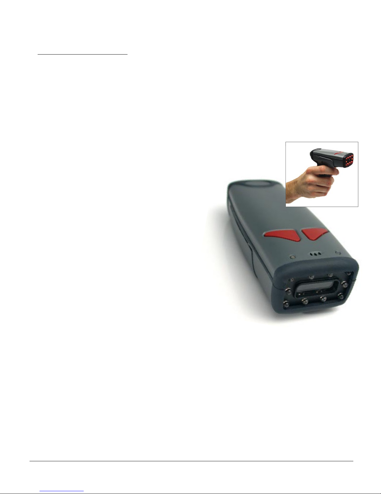
CR2 is a revolutionary new bar and 2-dimensional code reader. Developed to be the first universal
reader, no other single device performs as many functions. With a cost of ownership far less than
comparable systems, the CR2 incorporates a unique dual path optical system, a 1.3 million pixel
CMOS sensor, and a 400 MHz processor. This combination has created a reading system that supports:
• High density matrix codes and larger low density linear codes
• Superior working range
• High-speed omni-directional decoding
• Cordless and cabled interfaces
• Unsurpassed data rates
The CR2 sets a new benchmark for size and weight.
It is smaller and lighter than comparable systems yet
can withstand multiple drops to concrete. It is the only
product available in handheld, gun handle, and
presentation stand form factors with cabled, batch
and cordless versions. The cordless version utilizes
the latest Bluetooth™ class 1 radio with a 300 foot
operating range. The CR2 is rugged and lightweight
and the cordless version will operate for more than
a complete shift at the highest use rate. The CR2
performs more than 3000 reads and transmits from a
single battery charge. The CR2 will automatically
discriminate between all major 2-D matrix and linear
bar code symbologies and features a timestamp
feature for logging data.
Whether you need a small, palm-held device or a traditional gun, CR2 was specifically developed
so users may easily choose the device that best meets their needs. The CR2 is available in three
basic configurations:
1. CR2 Cabled - USB, RS232 or PS/2 interfaces
2. CR2 Batch - Store and forward device with memory and long-life battery
3. CR2 Cordless - Long life battery and Bluetooth radio
Save Settings
C001537_04_CR2 User Manual - 2

1.2 - Unpacking
Remove the imager from its packing and inspect it for damage. If the scanner was damaged
during shipping, please call Code at (801) 495-2200.
The standard CR2 unit is shipped with a USB cable interface. The unit also features a battery
blank that must be installed in the unit at all times.
Various accessories are available for the CR2.
• 3 cable options (USB, RS232 or PS/2)
• 1400 mAH or 1950 mAH long-life Lithium-Ion battery
• Class 1 Bluetooth radio with 300 foot operating range
• Clip-on pistol grip handle
• External battery charger
• CodeXML Bluetooth modem
Please keep your packing materials. The CR2 is shipped in an approved shipping
container and should be used if you ever need to return your equipment for servicing.
1.3 - Targeting and Reading Techniques
The CR2 utilizes digital camera technology to take a picture of a symbol. Once an image is captured,
the CR2 utilizes advanced decoding algorithms to extract data from the captured image.
The CR2 is available as a palm-held unit or users may purchase a clip-on pistol-grip handle.
The palm held unit features left and right triggers (figure 1.1). These triggers may be programmed to
perform various features. The reader is shipped with the left trigger and right trigger functioning as a
decode symbol command.
The clip-on pistol-grip handle features a trigger on the handle (figure 1.2). The two triggers on the top
of the unit also work when the handle is attached.
Figure 1.1
Save Settings
Figure 1.2
Note: The trigger on the handle attachment is light.
Squeezing to hard may damage the unit.
C001537_04_CR2 User Manual - 3
1.3 - Targeting and Reading Techniques (con’t)
To read a symbol with the CR2:
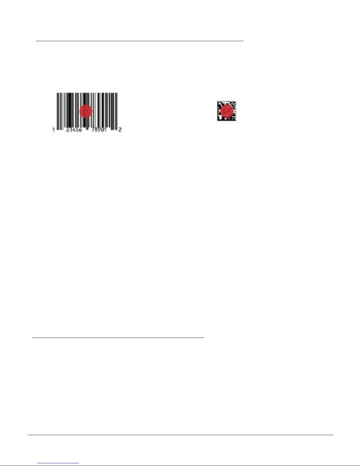
1. The CR2 features omnidirectional decoding. Center the symbol in any orientation within
the laser dot aiming pattern (figure 1.3).
Figure 1.3
Note: The CR2 can read a symbol that is not centered however, the CR2 performs best
when a code is centered. If two (2) bar codes are with the imagers decode zone, the CR2
will decode the symbol closest to the center of the aiming dot.
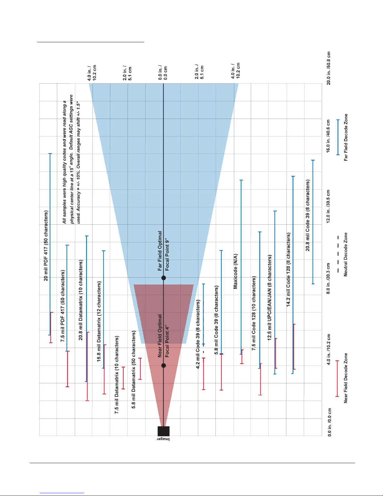
2. The CR2 was developed to decode both very small 2-dimensional symbols and larger
1-dimensional symbols. The unit features two imagers to create an innovative dual
decode zone. The CR2 features a high speed processor and DECODES BOTH
ZONES SIMULTANEOUSLY. The unit has one imager focused on a near-field for
smaller codes (optimal focal point is 4 inches) and one imager focused on a far-field
for larger codes (optimal focal point 9 inches). To read smaller symbols move the CR2
closer to the symbol. To read larger symbols move the unit farther away from the
symbol (see figure 1.4). The entire CR2 decode zone varies between two (2”) and
twenty (20+”) or more inches.
3. Hold the CR2 still - DO NOT SWIPE OR MOVE THE READER. Press the
trigger until the CR2 beeps, indicating the code has been successfully decoded.
4. The reader may be optimized to your specific environment by scanning codes in Chapter 3.
1.4 - Imager Field of View & Resolution
The CR2’s dual field optical system may be modified based on your scanning environment. The
CR2’s megapixel imager may be set to the following two modes:
SXGA Mode: In standard SXGA mode (default), the 1.3 Million Pixel imager is divided into near field
and far field decode zones. In each zone the resolution is 1024 x 640 pixels (see figure 1.4). In this
mode of operation the reader utilizes the highest resolution creating the widest working range on
bar code and 2-dimensional symbols of all densities. The trade-off is the amount of time the reader
spends processing the image. This time can be reduced by optimization functions:
Save Settings
C001537_04_CR2 User Manual - 4

1.4 - Imager Field of View & Resolution (con’t)
If only the near field is used (small, high density symbols), the far field image can be ignored. If only
the far field is used (large, lower density symbols), the near field can be ignored. Further optimization
may be obtained by "windowing" the field to a smaller area. Each focal area may be narrowed by
enabling the windowing feature found in section 9.3.
VGA Mode: In VGA mode (optional selection), the 1.3 Million Pixels are sampled on a 4-to-1 basis.
This greatly reduces the amount of time necessary for the transfer of the image to the CPU and the
resulting processing time (figure 1.5). The trade-off for this increased speed is a reduction in resolution
and working range.
1024
SXGA
Imaging Area
Far
Near
480
Far
640
640
Figure 1.4
320
VGA
Imaging Area
Save Settings
Near
320
Figure 1.5
C001537_04_CR2 User Manual - 5
1.5 - CR2 Decode Zone
Save Settings
C001537_04_CR2 User Manual - 6

Chapter 2 - Installation Guides
Save Settings
C001537_04_CR2 User Manual - 7
2.1 - Installation Guide - USB Interface
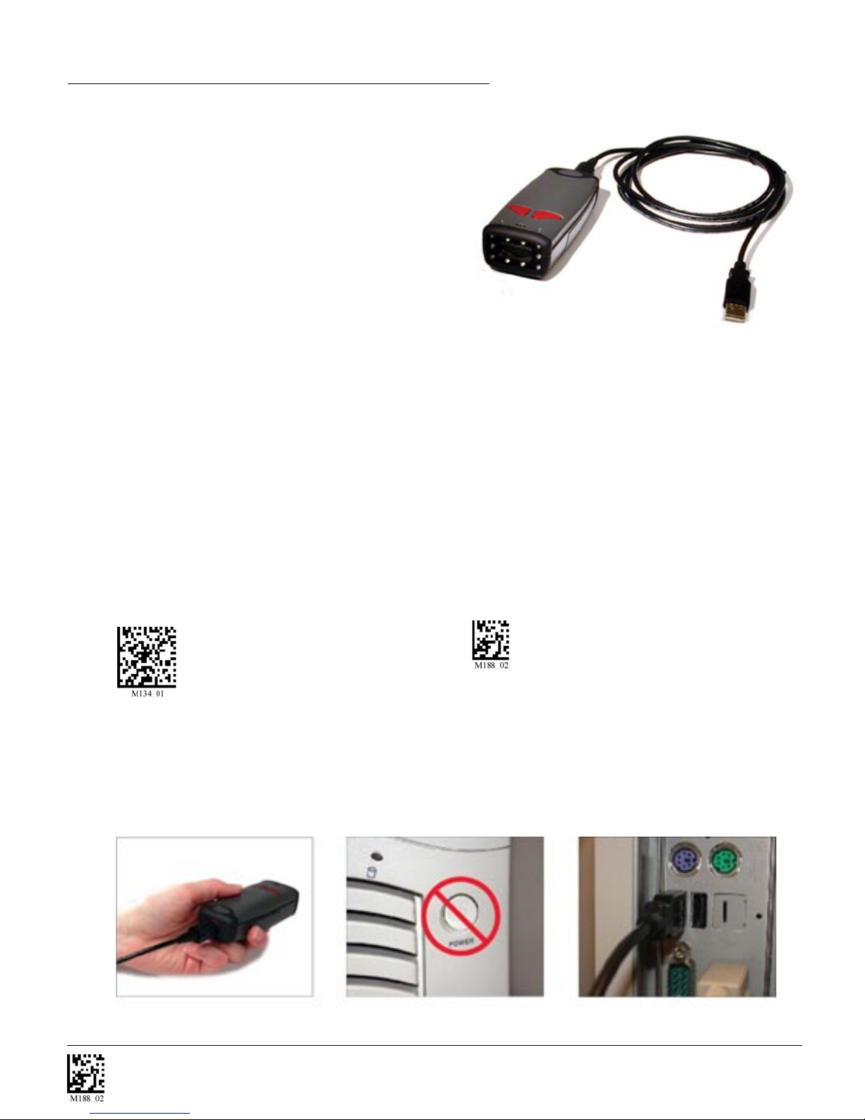
To connect the CR2 to your host computer via USB interface:
1. Make sure the USB cable is sufficiently
attached to your CR2 unit (figure 2.1).
2. You DO NOT need to power off your host
computer (figure 2.2). The CR2 with USB
interface can be plugged into any host while
the computer is powered up.
3. Connect the USB interface cable to the host (figure 2.3). If you are unsure of
the proper location to connect the USB cable please consult the manual of
your host computer.
4. The USB interface does not require additional power supply. If you are using
the 1400 mAH or 1950 mAH battery for batch mode, the CR2 will automatically recharge
the battery whenever the unit is a attached to a host that is powered up.
5. The CR2 will power on automatically.
6. Scan the USB Keyboard Mode code to then the Save Setting code to configure reader:
USB Keyboard Mode Save Settings
Note: For more information on other USB modes, please see section 5.2 of the CR2 Users
Manual
7. Your CR2 unit should be ready for use. Open the application you wish to send data and
begin scanning.
Figure 2.1
Save Settings
Figure 2.2
Figure 2.3
C001537_04_CR2 User Manual - 8
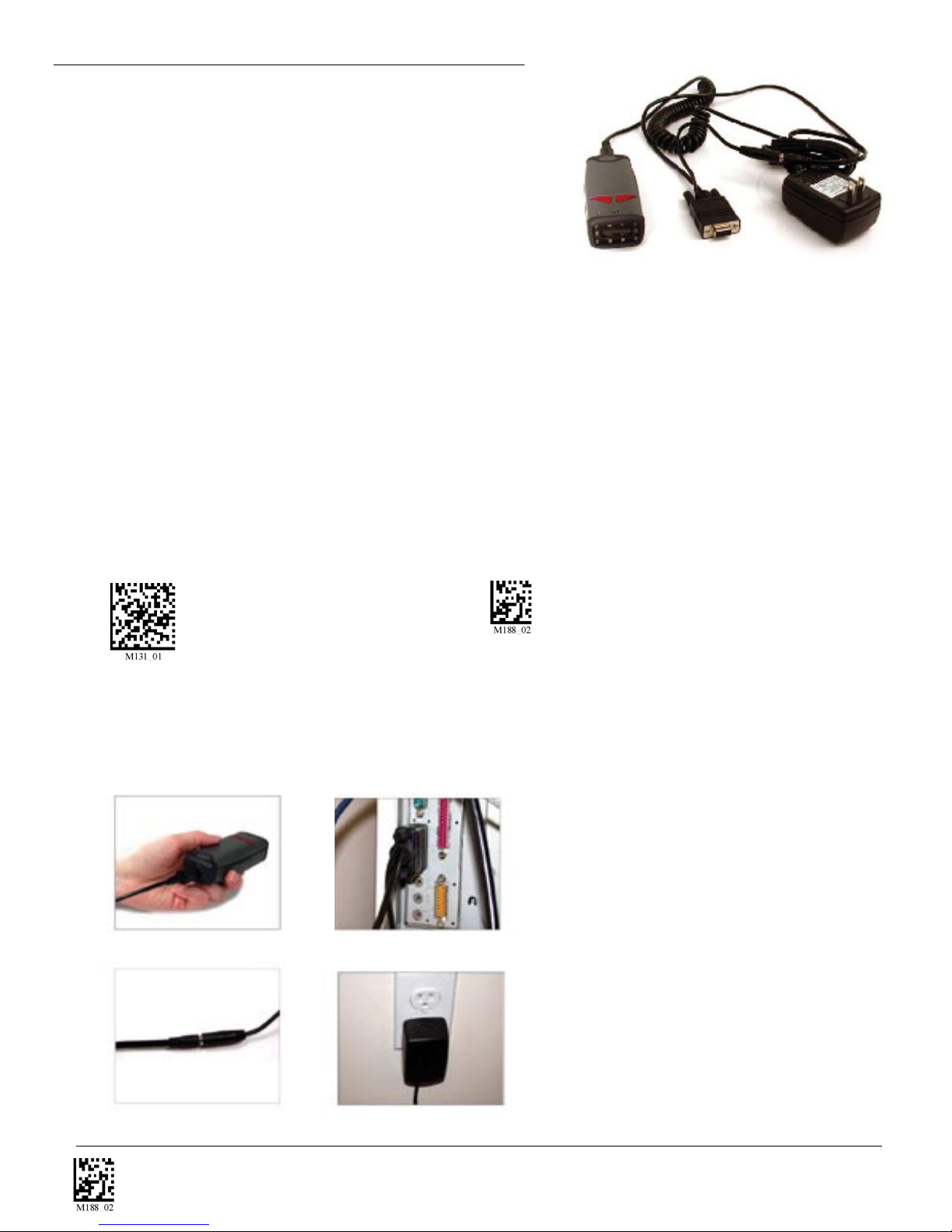
2.2 - Installation Guide - RS232 Interface
To connect the CR2 to your host computer via RS232 interface:
1. Make sure the RS232 cable is sufficiently attached to
your CR2 unit (figure 2.4).
2. Connect the RS232 interface cable to your host
computer (figure 2.5). If you are unsure of the proper
location to connect the RS232 cable please consult
the manual of your host computer.
3. The RS232 interface should have come with a power supply. Plug the power supply adapter
into the RS232 interface cable (figure 2.6) and then plug the power adapter into a wall socket
(figure 2.7). The RS232 interface does not require additional power. However, if you are using
the RS232 interface and utilizing Batch functionality, please read the Important Note in section
7.1. If you are using the 1400 mAH or 1950 mAH battery for batch mode, the CR2 will recharge
the battery whenever the unit is a attached to a RS232 cable that is plugged into a wall socket.
4. The CR2 will power on automatically.
5. Scan the RS232 One Way Mode code then the Save Settings code to configure reader:
RS232 One Way Mode Save Settings
Note: All Baud Rate, Parity, Stop Bit and Data Bit settings can be found in Chapter 5.
6. Your CR2 unit should be ready for use. Open the application you wish to send data and begin
scanning.
RS232 Factory Default Settings
Mode: RS232 One Way Mode
Max Range
Baud Rate 57600
Stop Bits 1
Figure 2.4
Figure 2.5
Data Bits 8
Figure 2.6
Save Settings
Parity None
Figure 2.7
C001537_04_CR2 User Manual - 9

2.3 - Installation Guide - PS/2 Interface
1. Power off the host computer.
2. Attach the end of the PS/2 cable with the single connector to the CR2.
A
3. If external keyboard exists, unattach your keyboard from the host and connect the appropriate
connector to the PS/2 cable .
4. Connect the other connector to host computer into keyboard port . The CR2 is
B
C
powered by the PS/2 port and does not require a power supply.
5. Set the CR2 to PS/2 mode by scanning the code below, then scan the Save Settings code:
PS/2 Mode Save Settings
6. Your CR2 unit is now ready. Open the appropriate application and begin scanning data.
Upgrade Note: The PS/2 model does not work with a USB cable. If you are upgrading the
firmware you must use an RS232 cable.
WARNING: Code does not recommend using Batch or Bluetooth Radio modes with the PS/2
interface because you need to disconnect the CR2 and the keyboard and this may result in the
host computer freezing and requiring you to reboot.
A
C
B
B
C
A
Code does not guarantee compatibility with all models of laptops.
Save Settings
C001537_04_CR2 User Manual - 10
2.4 - Bluetooth Radio Overview
Overview
This version of the CR2 features a Bluetooth® wireless radio. The radio allows for point to point
wireless communication with other Bluetooth devices that support serial port protocol (SPP).
The following guide will give you general instructions on connecting your CR2 to a desktop or
laptop computer with a Bluetooth radio.
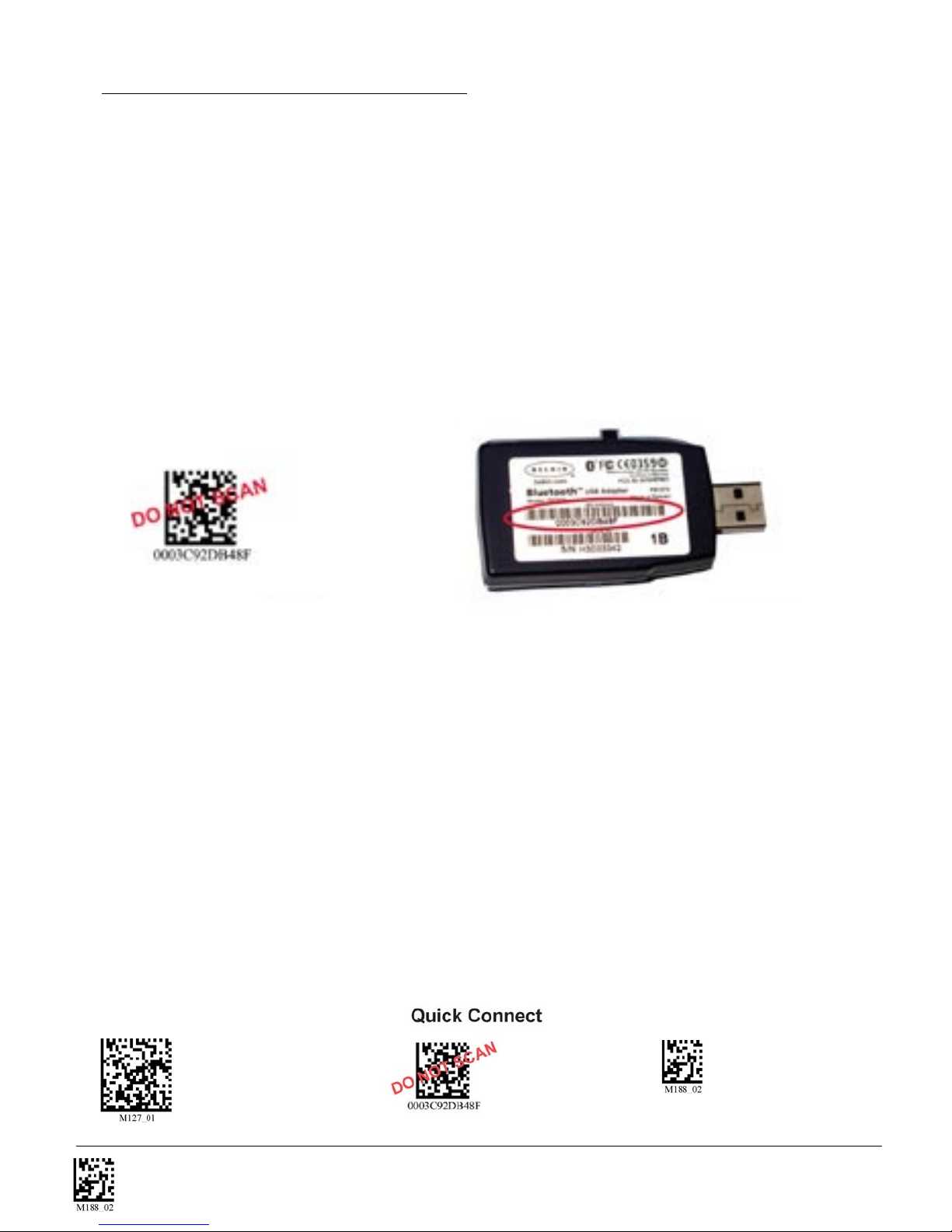
Connecting With A QuickConnect Code
The easiest way to connect to a Bluetooth device is to visit Code’s web site and create a QuickConnect
Code that is specific to your device (figure 2.9). This code will link your CR2 directly to the desired
Bluetooth device. To create a QuickConnect Code, you will need to know the Bluetooth address
(often referred to as the BD_ADDR) of that device. You can usually find the 12-character Bluetooth
address somewhere on the device near the device’s serial number (see figure 2.10).
Figure 2.9
Figure 2.10
If you purchased a CodeXML Bluetooth Modem or a Belkin® Bluetooth adapter from Code or from an
authorized distributor, a QuickConnect Code is included. The CodeXML Bluetooth modem is a simple
hardware solution for customers who wish to enjoy the benefits of cordless data collection without
modifying existing applications or installing software. Please visit www.codecorp.com for more
information. If you bought a Bluetooth adapter separately and wish to create a QuickConnect Code,
please visit Code web site at:
http://www.codecorp.com/support/bdaddr.php.
Note: While installing the Bluetooth Configuration Manager software that came with the adapter, make
sure to take note of the Virtual COM Port the software has assigned for the adapter (e.g. COM 10). This
is the COM Port your CR2 will connect through.
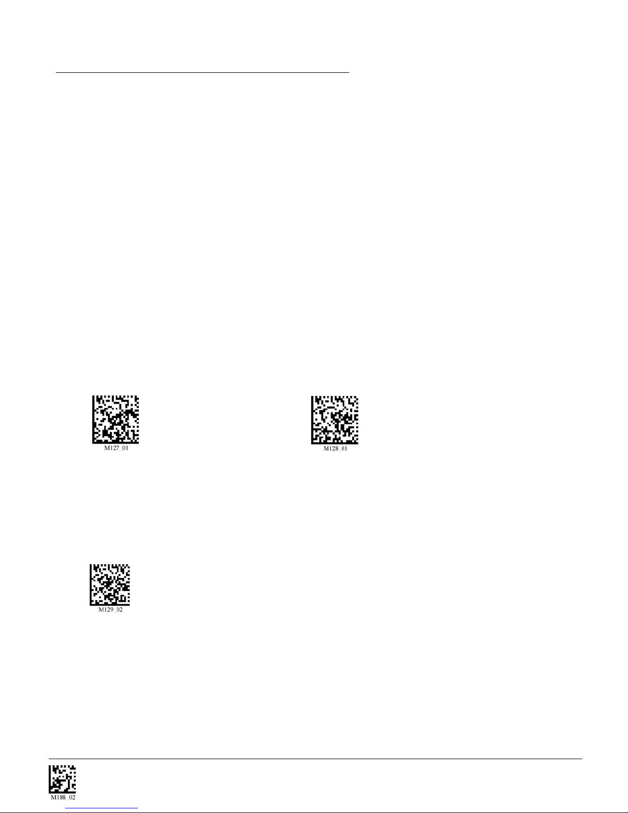
Scan the RF One Way - Max Range code (see discussion on next page) below then the QuickConnect
Code and your CR2 will automatically connect. You should also scan the Save Settings code if you want
to save these settings (Note: If the CR2 unit powers off without scanning the Save Settings code, you will
lose your settings).
RF One Way Mode (Max Range) Save Settings
Save Settings
C001537_04_CR2 User Manual - 11
2.4 - Bluetooth Radio Overview (con’t)
Radio Range and Transferring Data
The CR2 radio is a Class 1 device. If connected to another Class 1 device the unit has roughly
a 300 foot line of sight operating range. If connecting to a Class 2 or Class 3 device, the operating
range may drop to match the lower range. Once a unit is connected, the application software on
the host must be open to receive data.
When the CR2 detects the radio is out of range, the CR2 will store data on the reader’s non-volatile memory.
The reader will continue to try and send data until radio is back in range. Once the data is sent the data will
be erased from the units memory. If the radio cannot connect in 90 seconds, it will give an error beep. The
reader will continue to try and connect until it has reached the programmable radio time out setting.
The CR2 Bluetooth protocol allows for two (2) forms of communication:
1. One Way Mode - Defined as one way communication between the reader and host. One Way
mode only recommended when connecting to a device well within itse specified range or if
connected to a device without an operating system (i.e. printer). There are two settings in this mode:
• Max Range (Default) - Greater range but data reliability is lower
• Max Reliability - Limits range but reliability is improved
RF One Way Mode (Max Range) RF One Way Mode (Max Reliability)
Note: While robust, One Way Mode doesn’t guarantee data integrity and you may have data loss.
2. RF Two Way Mode - This is two way communication between the host and reader. This requires the
implementation of software at the application level.* The reader receives confirmation via packet
protocol verification and is 100% reliable. Data will be automatically retransmitted if necessary.
RF Two Way Mode
* Note: You will need to install application software that supports packet communication to operate
in RF Two Way Mode. Code offers a Windows or Pocket PC version of software called
CodeXML Router - Bluetooth Edition (BE) that provides for end-to-end Bluetooth handshakes that
eliminate out-of-range data loss. CodeXML Router - BE also offers Bluetooth to keyboard wedge
communication for applications that require keyboard port input.
If you are using the CodeXML Bluetooth modem, you must use RF Two Way Mode.
Save Settings
C001537_04_CR2 User Manual - 12

2.4 - Bluetooth Radio Overview (con’t)
Save Settings
Scan the code below to make the RF settings permanent on the reader:
Save Settings
Disconnecting from the Device
You may force disconnection by reading the disconnect code below (The CR2 may not appear
disconnected in the slave Bluetooth connection manager for 10 – 15 seconds after the command is
issued). The CR2 will also disconnect after 90 seconds of inactivity (Note: You may change the radio
frequency sleep time out setting however, it may reduce battery life).
Disconnect
Reconnecting to the Device
If the device is saved in RF mode it will automatically reconnect when:
1. CR2 is powered up
2. CR2 wakes from sleep mode
3. CR2 reads another code
Note: To set up more than one device, please consult Appendix E: “QuickConnect Codes”
Save Settings
C001537_04_CR2 User Manual - 13
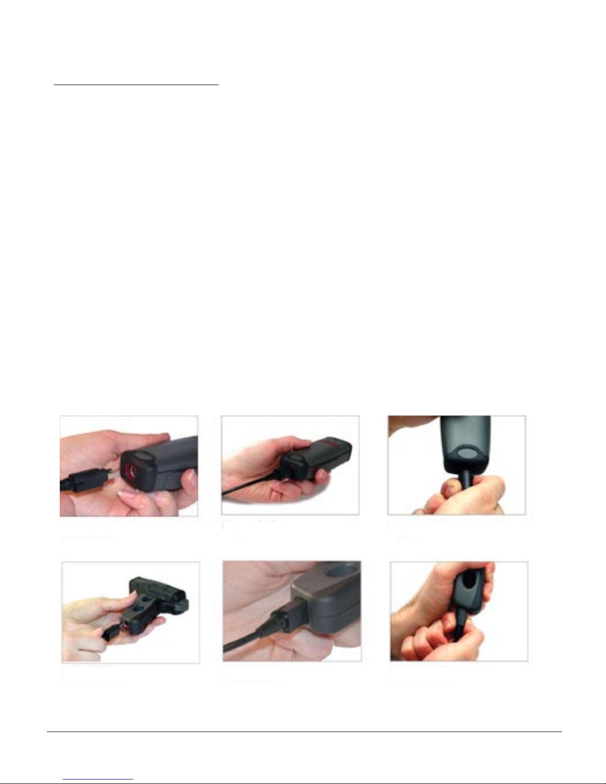
2.5 - Switching Cables
Attaching and Switching Cables
The CR2 is available with USB, RS232 and PS/2 cables. All of the cables are connected to the CR2
with a 8-pin DIN connector. Different cables may be required for different hosts.
Palm Held CR2
To install a cable on the standard palm-held unit, correctly line up the 8-pin DIN connector (figure 2.11)
into back end of the unit. The arrows on the connector should be facing down. When they are lined up,
firmly push the cable in (figure 2.12). To unattach, you must pinch the plastic on the 8-pin DIN and pull
back to disengage the connector (figure 2.13).
CR2 with Attachable Handle
If you purchased the attachable handle accessory (see section 2.6 for handle attaching instructions),
the 8-pin DIN connection is at the botton of the handle. Insert 8-Pin connector (figure 2.14) and firmly
push cable into the handle (figure 2.15). To unattach, you must pinch the plastic on the 8-pin DIN and
pull back to disengage the connector (figure 2.16).
Figure 2.11
Figure 2.14
Save Settings
Figure 2.12
Figure 2.15
Figure 2.13
Figure 2.16
C001537_04_CR2 User Manual - 14
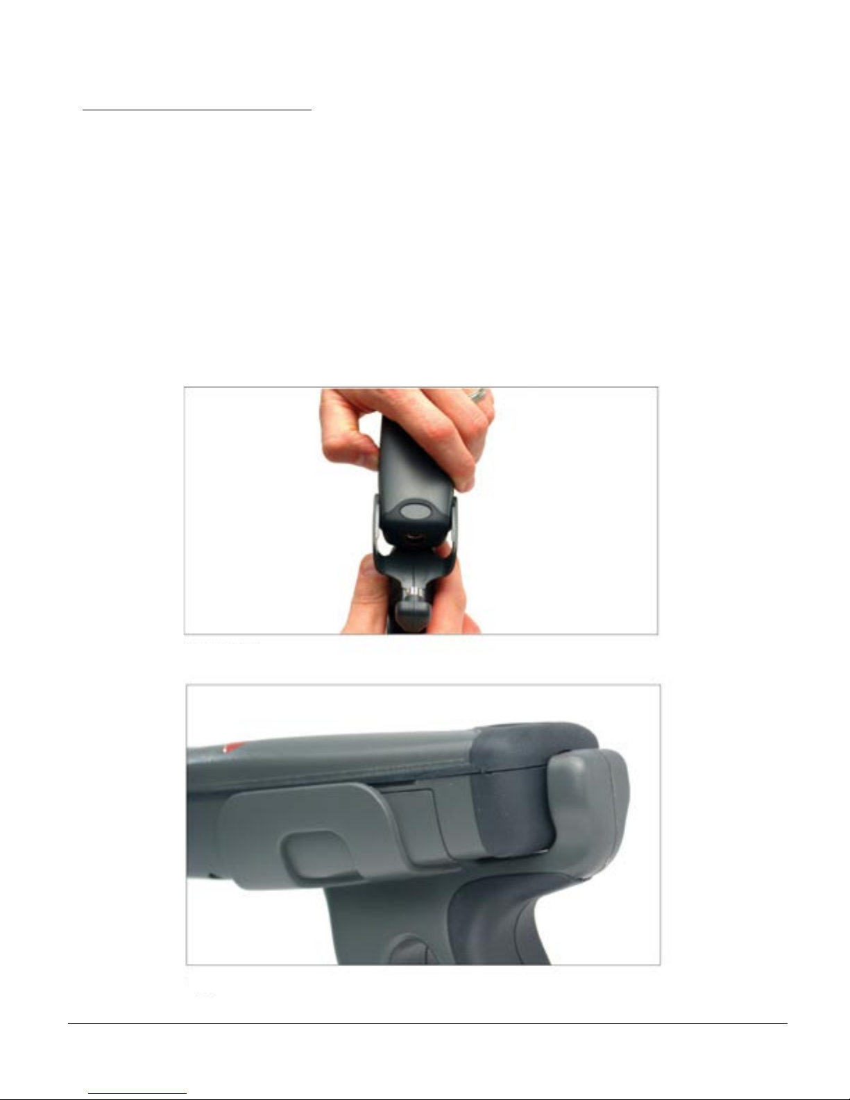
2.6 - Attaching Handle
Attaching the Handle
To attach the handle, please follow the following steps.
1. Place the CR2 in the cradle of the handle and slide the unit back (figure 2.17).
Be careful not to place fingerprints on the front glass when attaching handle.
2. Once the 8-pin DIN connector of the handle begins to enter the opening
in the back of the unit, firmly press the unit back until the unit is flush against
the handle (figure 2.18).
Save Settings
Figure 2.17
Figure 2.18
C001537_04_CR2 User Manual - 15
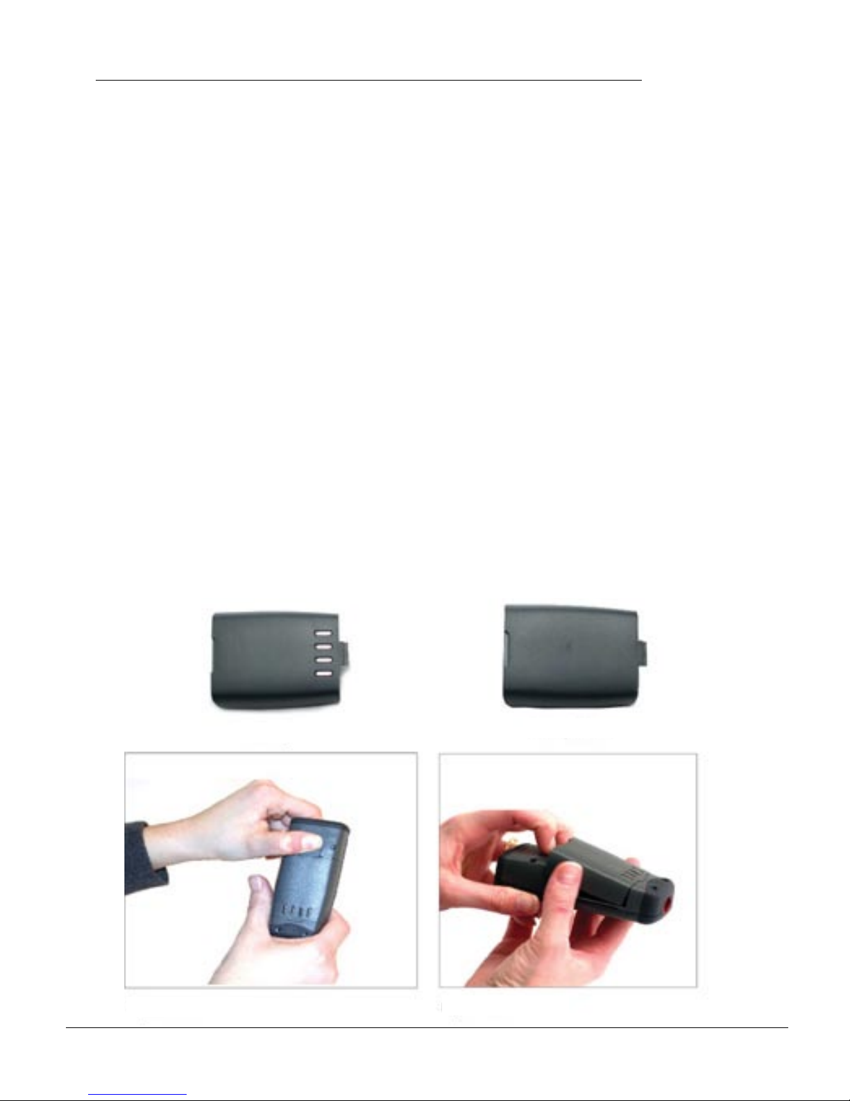
2.7 - CR2 Lithium Ion Battery and CR2 Battery Blank
CR2 Battery Blank
All cabled CR2 units feature a battery blank. THE BATTERY BLANK NEEDS TO BE ATTACHED
AT ALL TIME WHEN USING THE CR2. Installing the battery blank is identical to installing the
battery. Please follow the instructions below.
Attaching and Detaching the Lithium Ion Battery
The CR2 is available with a 1400 mAH or 1950 mAH Lithium Ion battery. If you wish to purchase,
contact a Code representative. To install battery or battery blank in cradle or to detach battery from
unit, push the locking mechanism up toward the front of the scanner and insert or detach battery
(figures 2.19 & 2.20).
Charging the Lithium Ion Battery
The battery automatically charges everytime a cable inteface is attached to the unit and the host is
powered up
Note: The RS232 interface power adapter must be plugged into a wall socket for the unit to charge.
If you power-up the CR2 with a completely discharged battery using the USB or RS232 cable it will take
up to 10 minutes before the until will become operational. The unit is held off until the battery
has enough charge to operate...this can take up to 10 minutes.
Battery
Battery Blank
Figure 2.19
Save Settings
Figure 2.20
C001537_04_CR2 User Manual - 16
 Loading...