

Page 1
Lighting Console
User’s Manual
Ver. 2.023
CODE ELECTRONIC CO., LTD.
http://www.codelight.com
Page 2

Page 3

i
Content
1. Welcome to Use the Phantom 1024......................................................................................................................................1
1.1. Setting up Phantom 1024 ......................................................................................................................................... 1
1.2. The Front Panel of Phantom 1024..........................................................................................................................1
1.2.1. Unit.............................................................................................................................................................2
1.2.2. Preset..........................................................................................................................................................2
1.2.3. Playback.....................................................................................................................................................3
1.2.4. Master.........................................................................................................................................................3
1.2.5. Attributes....................................................................................................................................................3
1.2.6. Function......................................................................................................................................................4
1.2.7. LCD Screen................................................................................................................................................4
1.2.8. Control wheels............................................................................................................................................4
1.2.9. Menu Soft-keys ..........................................................................................................................................4
1.2.10. Numeric keypad .........................................................................................................................................4
1.2.11. Action keys.................................................................................................................................................5
1.2.12. Other Devices.............................................................................................................................................5
1.3. The Rear Panel of Phantom 1024...........................................................................................................................5
1.3.1. DMX Output...............................................................................................................................................5
1.3.2. Audio Signal Input .....................................................................................................................................6
1.3.3. MIDI Output and Input...............................................................................................................................6
1.3.4. USB jack ....................................................................................................................................................6
1.3.5. Electrical Outlet and Power Switch............................................................................................................6
1.4. Clear All Data...........................................................................................................................................................6
2. Patch.....................................................................................................................................................................................7
2.1. Patch the Unit Address.............................................................................................................................................7
2.2. Patch Dimmer Channels...........................................................................................................................................7
2.3. Patch Fixtures...........................................................................................................................................................8
2.4. Setting up the Fixture Channels .............................................................................................................................10
2.5. View the Patching...................................................................................................................................................10
3. Manual Control of Dimmer Channels and Fixtures............................................................................................................11
3.1. View the output of the Console..............................................................................................................................11
3.2. Live Show Mode....................................................................................................................................................11
3.3. Manual Control of Dimmer Channels....................................................................................................................12
3.4. Manual Control of Fixtures....................................................................................................................................12
3.5. Run Macro.................................................................................................................
.............................................12
3.6. Change the Attribute Values of Fixtures.................................................................................................................13
3.7. Fixture Location and Fan Mode.............................................................................................................................13
3.8. Manual Clear..........................................................................................................................................................13
3.9. Using Group...........................................................................................................................................................14
3.10. Examples ................................................................................................................................................................14
Page 4

ii
Content
4. Preset..................................................................................................................................................................................15
4.1. Using the Preset Value of the Preset Buttons..........................................................................................................15
4.2. View the Preset Buttons .........................................................................................................................................15
4.3. Edit Preset ..............................................................................................................................................................16
5. Effect..................................................................................................................................................................................17
5.1. How Effect Generator Works.................................................................................................................................17
5.2. Select an Effect.......................................................................................................................................................17
5.3. Change Size and Speed of Effect ...........................................................................................................................18
5.4. Change Position of Effect.......................................................................................................................................18
5.5. Effect Spread..........................................................................................................................................................18
6. Playback.............................................................................................................................................................................19
6.1. What is HTP and LTP.............................................................................................................................................19
6.2. Program Playback ..................................................................................................................................................19
6.3. View the Playback..................................................................................................................................................20
6.4. Cue.........................................................................................................................................................................20
6.4.1. Two Record Modes of Cue.......................................................................................................................20
6.4.2. Three Run modes of Cue..........................................................................................................................20
6.4.3. Save Cue...................................................................................................................................................20
6.5. Chase......................................................................................................................................................................21
6.5.1. Create a new Chase .................................................................................................................................. 21
6.5.2. Edit Chase ................................................................................................................................................22
6.5.3. Speed of Chase.........................................................................................................................................23
6.6. Change Playback Page ...........................................................................................................................................23
6.7. Run Playback .........................................................................................................................................................23
6.8. Pre-position the LTP...............................................................................................................................................24
6.9. Playback Parameter................................................................................................................................................24
6.9.1. Change the Direction of Chase.................................................................................................................24
6.9.2. Change Link mode ...................................................................................................................................24
6.10. Runtime Parameter of Program..............................................................................................................................25
6.11. Change the Runtime Parameter Load Mode of the First Chase Step......................................................................25
7. Advanced Function.............................................................................................................................................................26
7.1. COPY..................................................................................................................................................................... 26
7.1.1. Copy Preset ..............................................................................................................................................26
7.1.2. Copy Playback..........................................................................................................................................26
7.1.3. Copy Unit Attribute..................................................................................................................................26
7.2. Delete.....................................................................................................................................................................27
7.2.1. Delete Preset.............................................................................................................................................27
7.2.2. Delete Playback........................................................................................................................................27
7.2.3. Delete Unit ...............................................................................................................................................28
7.3. Off..........................................................................................................................................................................28
7.4. Rapid Select ...........................................................................................................................................................28
7.5. Lock the Console....................................................................................................................................................28
Page 5

iii
Content
7.6. Rename Preset, Playback and Group......................................................................................................................29
7.7. Set up the Channel Level........................................................................................................................................29
7.7.1. Control the designated Unit Channel........................................................................................................29
7.7.2. Control Group of Dimmer Channels ........................................................................................................29
8. Fixture Library Supervise...................................................................................................................................................30
8.1. View System Fixture Library .................................................................................................................................30
8.2. User Fixture Library...............................................................................................................................................30
8.2.1. User Fixture Supervise.............................................................................................................................30
8.2.2. Load R20 File...........................................................................................................................................33
8.3. Update the Library .................................................................................................................................................33
9. Setup...................................................................................................................................................................................34
9.1. Archive Menu Backup............................................................................................................................................34
9.1.1. Upload the Data........................................................................................................................................34
9.1.2. Backup the Data .......................................................................................................................................34
9.1.3. Utilities of USB Flash Driver...................................................................................................................35
9.2. Set up the System Parameters................................................................................................................................. 36
9.2.1. Upgrade the Software...............................................................................................................................36
9.2.2. Clear Internal Data ...................................................................................................................................36
9.3. User Setup ..............................................................................................................................................................37
9.3.1. Set Up Language......................................................................................................................................37
9.3.2. Set Up MIDI.............................................................................................................................................37
10. Technological Specification................................................................................................................................................39
Page 6

Page 7
Phantom_1024_V2.023_en.PDF http://www.codelight.com
1
1. Welcome to Use the Phantom 1024
The Phantom 1024 is a special console for intelligent lights and dimmer packs.
For your convenient usage, the manual is divided into 10 chapters. Important contents are highlighted by shading
and example explanations are added when necessary for the sake of your better understanding.
In the manual, a square symbolizes a button, e.g. Enter,while a square brackets symbolizes a menu item
(corresponding 6 buttons on the right of LCD Screen) shown on the LCD Screen, e.g. [FileSystem].
1.1. Setting up Phantom 1024
You need to prepare the following connection before using Phantom 1024:
Connect Phantom 1024 with AC power supply;
Note: Check whether the local power supply is within the range of 100V-240V.
Connect the fixtures with DMX cables.
There are 2 groups with 4 optically isolate DMX output jacks in Phantom 1024, thus A, B ports.
DMX512 protocol regulates that there are 512 channels. That means actually, Phantom 1024 use two
groups of output ports with 512 channels each.
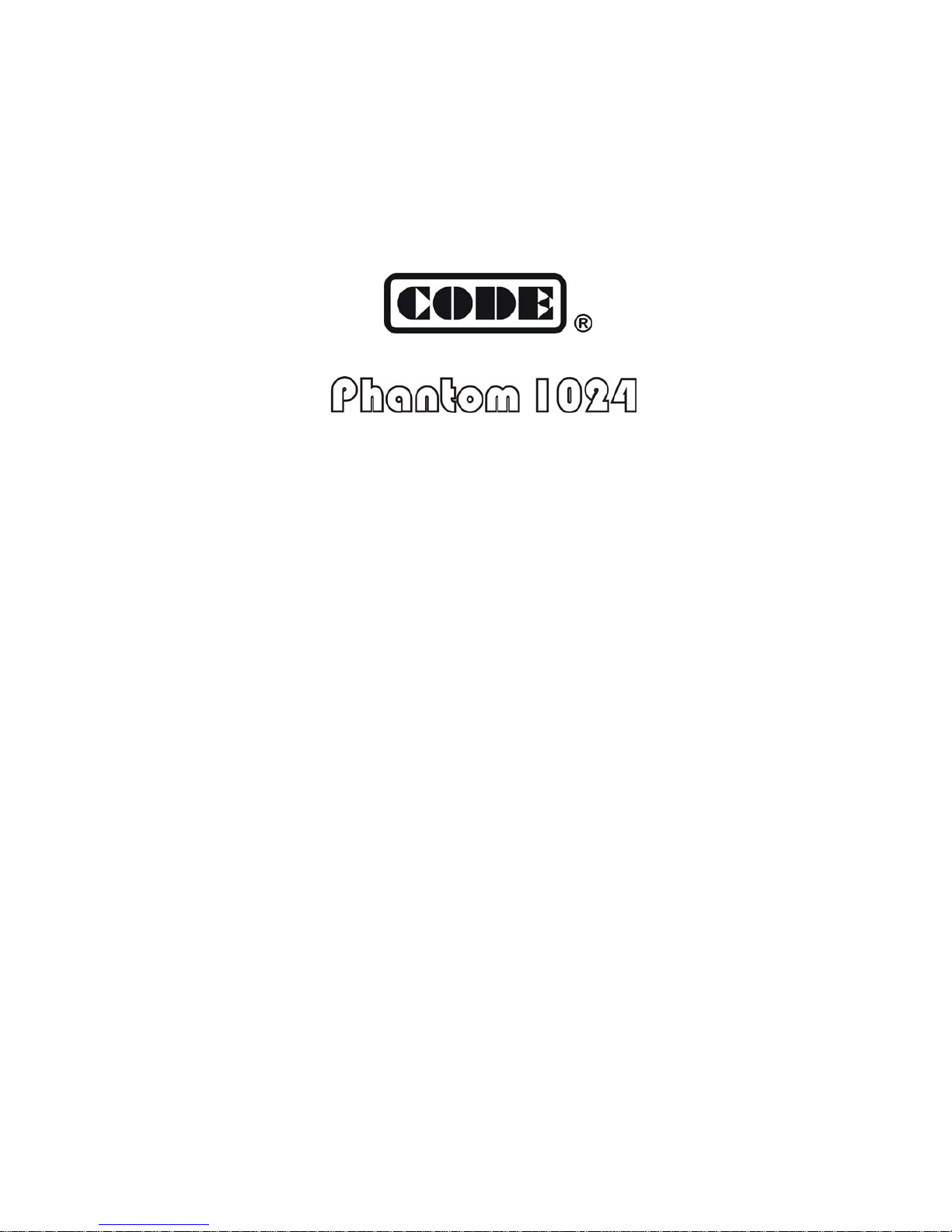
1.2. The Front Panel of Phantom 1024
Page 8
Phantom_1024_V2.023_en.PDF http://www.codelight.com
2
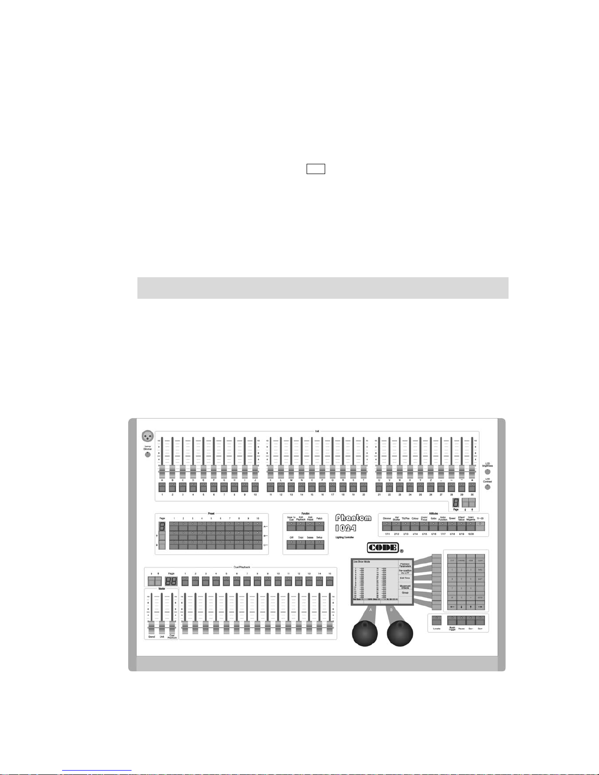
1.2.1. Unit
Unit section comprises of Unit page, Unit faders and Unit buttons.
One unit can be patched to a fixture, or a channel which can compose of one or more dimmers.
Unit page: Phantom 1024 has 8 Unit pages, each of which can be patched to 30 Units. Thus, 8 pages can
totally control 240 Units. Pressing or can change the page, led number display the present Unit page.
Each fader can control the light level of a fixture or a channel. Fade in or out will change the brightness of
the fixture or channel that had been patched.
The buttons under the Unit faders are the selecting button for the Units. Two functions of them are:
1. Select the Units;
2. Fast enter English letters and symbols.
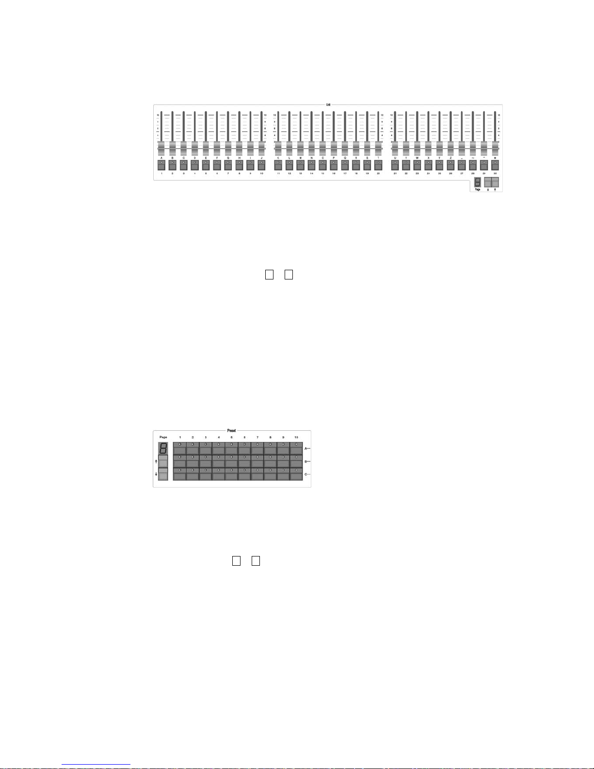
1.2.2. Preset
Preset section comprises of Preset pages and Preset buttons.
Phantom 1024 has 7 Preset pages, each of which has 30 Preset buttons. Therefore, there are totally 210
Preset buttons. Pressing or can change the page, led number display the present Unit page.
There are 30 Preset buttons on the Front panel, divided into 3 rows, distinguished each other by A, B and
C. After finishing the Unit patching, the 30 Preset buttons of the 1st preset page are patched to the value of
attributes of the Units. For instance, the 1
st
row A is controlling the colours, the 2nd row B is controlling
the gobos and the 3
rd
row C is controlling the locations. The 10 buttons in each row are preset as different
attribute values. For example, if you press A1, all the patched fixtures will show white light beam. You
can set up the Preset buttons of other pages.
Page 9
Phantom_1024_V2.023_en.PDF http://www.codelight.com
3
1.2.3. Playback
Cue/Playback section contains Playback pages, Playback faders and Playback buttons.
Phantom 1024 contain 40 Playback pages, each of which contains 15 playback faders. So, it can memorize
600 Effects. Pressing or can change the page, led number display the present Unit page.
All the preset Cue and Chase need to be saved in the Playback. You can use faders to playback the
programmed Effects.
There are 15 playback buttons which above Playback faders, has three functions:
1. The Flash function of Playback. When you don’t fade in the Playback faders, you can press and
hold still the button to run the program, which as the same as you fade in the Playback fader. The
program will be turned off as soon as you release the button.
2. The manual function of Playback. After fade in the fader, the button is used for manual operation,
to run one-step of the playback. (Notice: you must set the steps of the playback to Link Off, or set
the link mode of playback to manual when it is running).
3. Press Shift + Playback buttons to switch the present effective Playback. (You can use the control
wheels to change the speed of the present Playback program.)
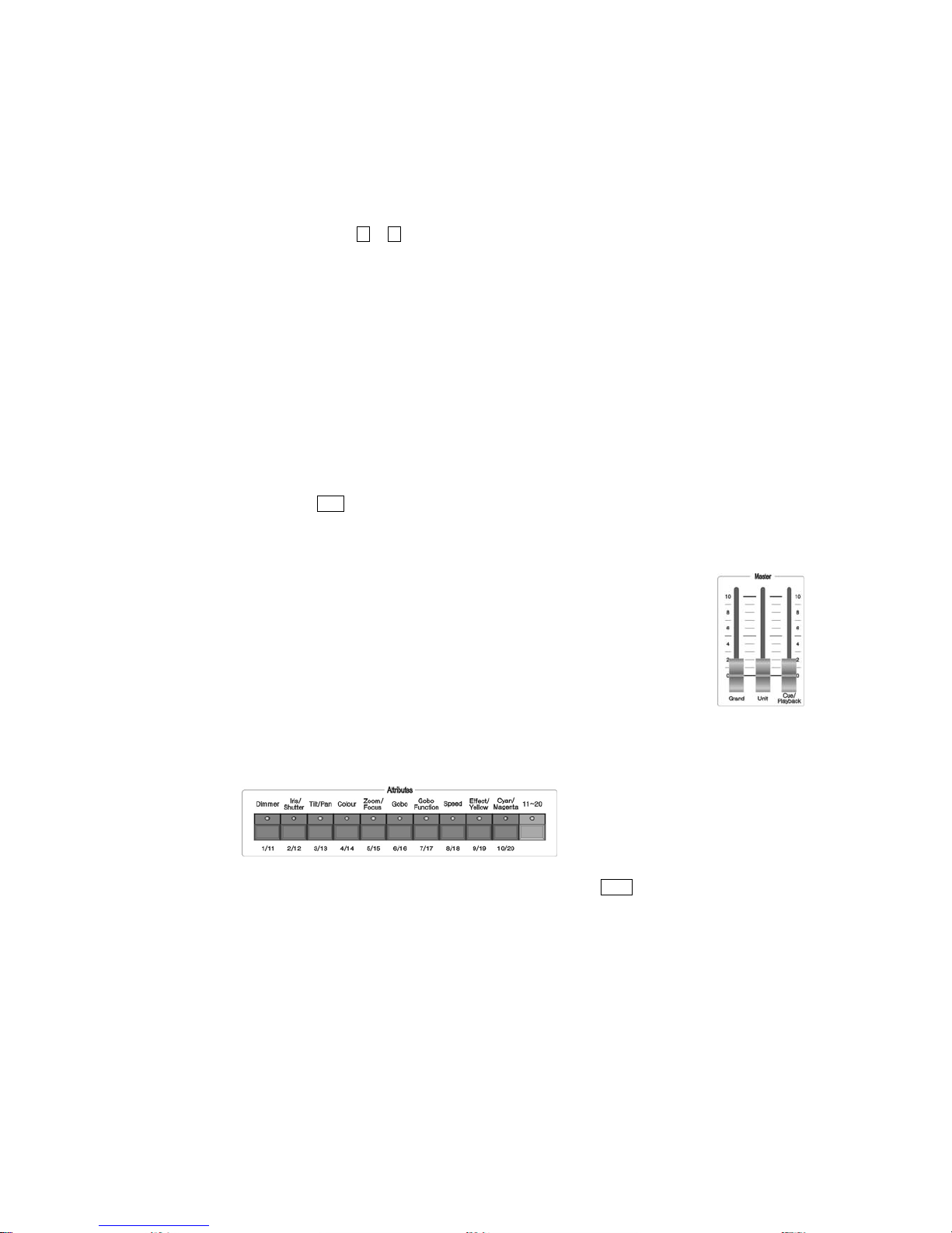
1.2.4. Master
There are 3 faders in the Master section.
Grand – controlling the general output level;
Unit – generally controlling the faders in the Unit section;
Playback – generally controlling the Playback..
1.2.5. Attributes
In the Attributes section, there are 10 Attribute buttons and one 11-20 switch button. Usually, the ten
attribute buttons stand for the 10 attributes printed on the board; after press the switch button, they
symbolize another 10 attributes, that’s the 11-20 attributes. After you select the units, using these attribute
buttons with control wheels, you can set up the assigned attributes of the Units.
According to the differences between various fixtures, the LCD screen will display the name of the
attribute after you press the Attribute buttons. Each Attribute button can carry 2 attributes, and the LCD
screen also shows you which attribute will be controlled by wheel A or B.
Page 10
Phantom_1024_V2.023_en.PDF http://www.codelight.com
4
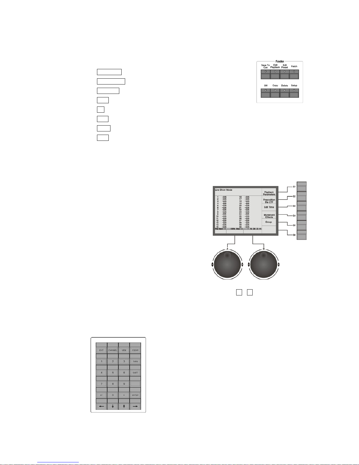
1.2.6. Function
There are 8 buttons in the Function section:
Save to Cue --- save the Playback program of Cue;
Edit Playback --- establish and setup Playback;
Edit Preset --- edit the Preset;
Patch --- patch the Units;
Off --- close some Units;
Copy --- copy function;
Delete --- delete function;
Setup --- setup the Console.
1.2.7. LCD Screen
Display diversified information under various circumstances.
1.2.8. Control wheels
The wheel A and B are used to setup all the attributes
values of the Units, as well as all the controlling
parameters of the Effects.
1.2.9. Menu Soft-keys
On the right of the LCD screen, there are 6 Soft-keys, the
functions of which depend on the present state of the
console. Under different situations, the enabled functions of the keys are displayed on the corresponding
place of the LCD screen. For convenient, keys from the top down we use S1 – S6 instead.
1.2.10. Numeric keypad
There are 24 buttons in the Numeric keypad. Their functions will be illustrated in the following chapter.
Page 11

Phantom_1024_V2.023_en.PDF http://www.codelight.com
5
1.2.11. Action keys
There are 5 buttons with led in the Action section:
Locate --- if you press this button, the selected fixtures will display white light beam. The positions of
Pan/Tilt are preset in the middle, so you can easily find out the fixtures and locate them according to
your need.
Music Trigger --- music trigger of Chase.
Pause --- Chase pause.
Go + --- Chase in order.
Go - --- Chase in reverse order.
1.2.12. Other Devices
On the upper-left corner of the front panel, there is a jack for a 12V gooseneck working
light, under which is the dimmer of it.
on the upper-right corner, there are 2 knobs. The upper one is to adjust the brightness of
the LCD screen, while the lower one is to adjust the contrast of the LCD screen.
1.3. The Rear Panel of Phantom 1024
1.3.1. DMX Output
“DMX Output 1” exports the signals of 1 - 512
channels (A port);
“DMX Output 2” exports the signals of 1 - 512
channels (B port).
DMX512 protocol regulates that there are 512 channels. So, Phantom 1024 actually use two output ports
with 512 channels each, that’s to say, 1024 DMX output channels are composed of 1-512 channels from A
port and another 1-512 channels from B port.
Page 12
Phantom_1024_V2.023_en.PDF http://www.codelight.com
6
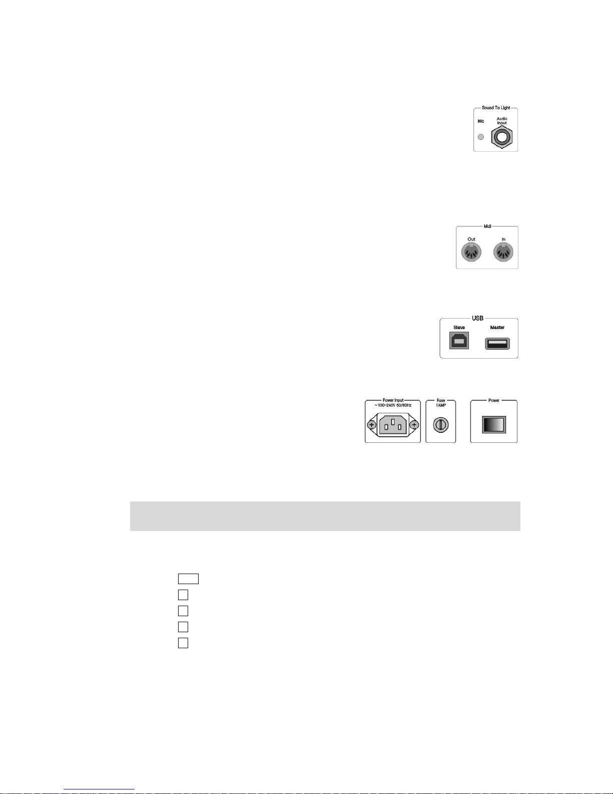
1.3.2. Audio Signal Input
Phantom 1024 can pick up the bass and rhythm of the audio signal to trigger Chase, so
that Chase can automatically follow the bass rhythm of the audio. There are two ways to
input the audio signals: one is through a 1/4 inch stereo plug; the other is by the
microphone of the console. After the stereo jack is plugged, the console will use the audio
signals from the stereo cable, otherwise, it will use the microphone to pick up the sound.
1.3.3. MIDI Output and Input
Console not only can be controlled by the MIDI signals, but also can send out MIDI
signals to control another Phantom 1024. Please refer to the relevant chapter for
further information about the controlling orders.
1.3.4. USB jack
You can use USB to backup the console data, update the light library, as well as
update the interior programs.
1.3.5. Electrical Outlet and Power Switch
Phantom 1024 can adjust itself to a very wide voltage
range (100-240VAC, 50-60Hz). Thus, it can be used
worldwide. If you need to change the fuse, please pull out
the power supply cable to insure a save operation.
1.4. Clear All Data
Note: All the data in the console, including all the fixture patch, preset and playback, will be cleared, except the
uploaded fixture library.
You’d better clear all data in the newly-bought console, so that you can avoid the unpredictable errors, caused by
disorder of the mixed patch.
Press Setup in Function section to enter the “User Supervise Menu”;
Press S4 [System Parameters] to enter “System Setup” menu;
Press S4 [Internal data Clear];
Press S5 [Clear All Data];
Press S1 [Confirm] to clear, it will return to “Live Show Mode” after finish cleared.
Page 13
Phantom_1024_V2.023_en.PDF http://www.codelight.com
7
2. Patch
We will introduce how to patch dimmer channels and fixtures in this chapter:
Patch DMX address of Units;
Patch dimmer channels;
Patch fixtures;
Setup the fixture channels;
Look over the Unit patch.
In order to make the Phantom 1024 to control your Units, you should first patch the Units. Each Unit fader can be
patched to a channel or a fixture.
First of all, connect all the dimmers and fixtures by DMX cables. Then, patch every channel or fixture to each Unit
button. Phantom 1024 contain 8 Unit pages, each of which can be patched to 30 Units. So you can patch up to 240
Units by changing pages.
2.1. Patch the Unit Address
When you patched dimmer channels or fixtures, Phantom 1024 will automatically distribute the free DMX
addresses to avoid the overlap, discontinuity and waste of DMX addresses. You can also assign the DMX address
of fixtures and dimmers by manual patching to carry out your preconcerted design, but you must make sure the
DMX addresses don’t overlap with each other.
When patching dimmer channels and fixtures, LCD screen will list the present patched addresses of the Units and
those free DMX addresses, marked as Free.
2.2. Patch Dimmer Channels
Each Unit fader can be patched to a dimmer channel. After patching, you can control the brightness of the dimmer
channel. A dimmer channels comprise of one or more DMX addresses. If you change the level of a dimmer
channel, dimmers of the DMX addresses controlled by the channel will get the same brightness value.
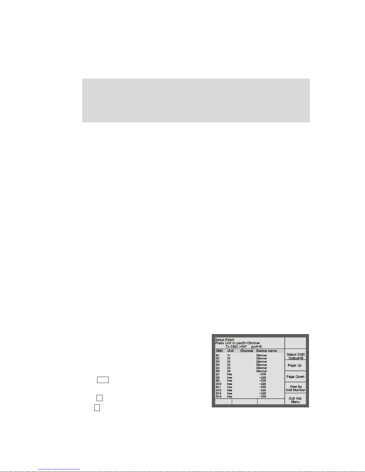
Example: Use 1
st-6th
addresses of DMX output port B, to patch
a 6 channeled dimmer to the No. 21-26 Unit button of 1
st
page in
Unit section, so that each of the 6 Unit faders can individually
control 1 dimmer channel, thus each Unit button control a
dimmer channel.
Press Patch in the Function section to enter “Setup Patch”
menu;
Press S2 [Patch Dimmer] to enter the menu;
Use S2 to select [Select DMX Output = B] mode. Now the
LCD screen display the patching state of port B. “Free” means it’s not patched;
Press 001 by the Numeric keypad to set the DMX initial address as 1;
Page 14
Phantom_1024_V2.023_en.PDF http://www.codelight.com
8
Press No. 21-26 Unit buttons in the Unit section in turn to finish the patching of DMX address 1-6 to Unit
21-26;
Press Patch to exit patching and return to “Live Show Mode”.
Example: Use DMX address 7th-12th of DMX output port B to patch a 6 channeled dimmer to Unit 30, that’s one
Unit button control 6 dimmer channels.
Press Patch in the Function section to enter “Setup Patch”
menu;
Press S2 [Patch Dimmer] to enter the menu;
Use S2 to select [Select DMX Output = B], then the LCD
screen will display the patching information of Port B,
“Free” means the channel is not patched;
Press 007 by the Numeric keypad to set the DMX initial
address as 7
Press Unit button 30 for 6 times to complete the patching of DMX address 7-12 to Unit 30;
Press Patch to exit the patching and return to “Live Show Mode”.
2.3. Patch Fixtures
Fixture patching is a little bit different from dimmer channel patching. Dimmer channels have only one attribute,
brightness, while fixtures have many attributes. After the patching of fixtures, you can use the faders to change the
brightness, but other attributes not.
There are two types of Libraries in the console:
1. System fixture Library. The console has been uploaded the latest light library when it’s on sale. You can
visit our website to download the newest library and upload it to your console.
2. User fixture Library. When you can’t find the model of your fixtures in the System Fixture Library, you can
build one yourself.
When choosing the fixture, you can look over the details of the fixture, to make sure your choice correctly.
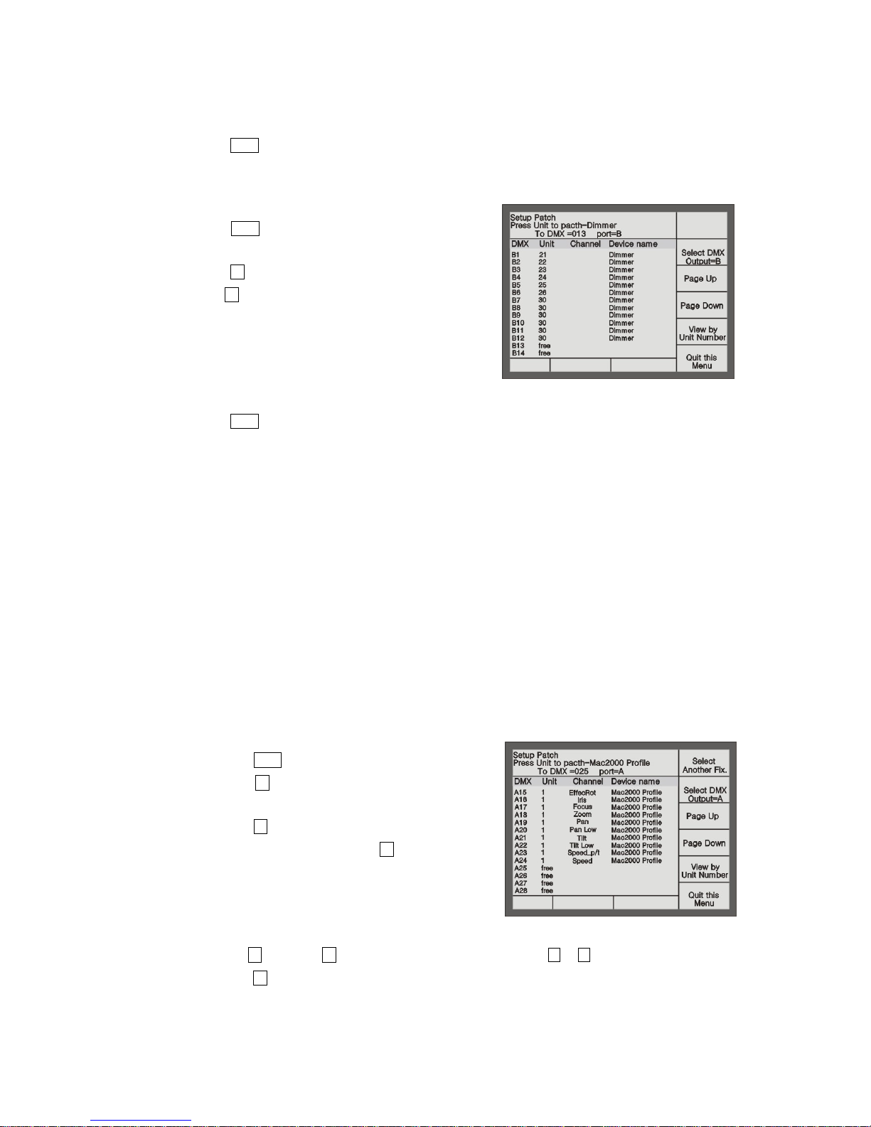
Example: Patch a Martin Mac2000 Profile fixture with 24 channels to Unit button 1 of the 1
st
page, using port A
of DMX output, DMX initial address =1.
Press Patch to enter “Setup Patch” menu;
Press S3 [Patch Fixtures] to enter “Select a Library”
menu;
Press S1 [System Fix. Library];
Select the sort order mode with S5. Here, we search by
Manufacturer;
Use Unit buttons (with English letters) to fast skip to
the initial letter of the Manufacturer. Here, we press
Unit 13 (the letter M);
Use S3 [Page Up], S4 [Page Down] to switch the pages, use the or button to select Martin. Then
press S1 [Confirm], it will display all fixture models of Martin;
Use Unit buttons (with English letters) to fast skip to the initial letter of the fixture model. Here, we press
Unit 13 (the letter M);
Page 15

Phantom_1024_V2.023_en.PDF http://www.codelight.com
9
Use S3 [Page Up], S4 [Page Down] to switch the pages, use the or button to select Mac2000
Profile 24CH;
Here, press S3 to check up the channel details of the fixture, press S6 to return;
Press S1 [Confirm];
Use S2 to Select DMX Output = A;
Console will automatically patch the DMX initial address. You can patch manually by using the Numeric
keypad if necessary;
Select page 1 of Unit section and press Unit button 1;
Press S6 to return;
Press Patch to exit.
Example: Patch 9 Martin Mac2000 Profiles with 24 channels to Unit buttons 2 - 10 in the 1st page and use DMX
output port A.
Press Patch to enter “Setup Patch” menu;
Press S3 [Patch Fixtures] to enter “Select a Library”
menu;
Press S1 [System Fix. Library];
Select the sort order mode with S5. Here, we search by
Manufacturer;
Use Unit buttons (with English letters) to fast skip to
the initial letter of the Manufacturer. Here, we press
Unit 13 (the letter M);
Use S3 [Page Up], S4 [Page Down] to switch the pages, use the or button to select Martin. Then
press S1 [Confirm], it will display all fixture models of Martin;
Use Unit buttons (with English letters) to fast skip to the initial letter of the fixture model. Here, we press
Unit 13 (the letter M);
Use S3 [Page Up], S4 [Page Down] to switch the pages, use the or button to select Mac2000
Profile 24CH;
Here, press S3 to check up the channel details of the fixture, press S6 to return;
Press S1 [Confirm];
Use S2 to Select DMX Output = A;
Console will automatically patch the DMX initial address. You can patch manually by using the Numeric
keypad if necessary;
Select Unit page 1, press Unit button 2 and hold still until press Unit button 10, which can quickly patch
the selected fixtures to Unit button 2-10;
Press S6 to return;
Press Patch to exit.
Use S1 [Select another Fix.] can patch other different model of fixtures; S3 [Page Up] and S4 [Page Down] can
be used to view the patching.
Page 16

Phantom_1024_V2.023_en.PDF http://www.codelight.com
10
2.4. Setting up the Fixture Channels
By setting up the swap of Pan and Tilt, you can control fixtures, which is installed against the stage, to swap
Pan/Tilt axis, Invert Pan and/or Tilt, so that the mirror movement makes the control more direct and easier.
Dimming channel can be inverted too.
Note: The setup should be done before you program the show. Otherwise, errors of moving direction will occur in
running the program.
The dimming channel of the same fixtures will be inverted if you invert the dimming value.
Press Patch to enter “Setup Patch” menu;
Press S5 [Fixture Alignment];
Use or button to select the fixture you needed;
S1 for swap Tilt/Pan, S2 for Pan Invert and S3 for Tilt
Invert, S4 to invert the dimming channel of current
type of fixture;
Press S6 [Quit this Menu];
Press Patch to exit patching.
2.5. View the Patching
Use the button View in the Numeric keypad to view the Patch of Unit, Preset and Playback. By pressing button
View and holding still, then press Unit button, you can view the DMX address and the special setup of Pan/Tilt
channel.
The LCD screen when pressing the button View + Unit button 1 shown as follows:
Page 17

Phantom_1024_V2.023_en.PDF http://www.codelight.com
11
3. Manual Control of Dimmer Channels and Fixtures
We will introduce how to manually control dimmer channels and fixtures in this chapter.
Control dimmer channels and fixtures
Change attributes
Locate fixtures and Fan Mode
Group
View the output of the console
You can manually control all the dimmer channels and fixtures after finished patching them.
Choose the Unit (select the Page number in the Unit section and press the correlative Unit button);
Change their attribute value.
Shortcut: If you need to select Unit button 1-10, you only need to press Unit button 1 and hold still until you
press Unit button 10.
Note: If the Unit buttons have not been patched to any fixtures or dimmers, you can not choose Units and the
led of the Unit buttons will not be turned on.
3.1. View the output of the Console
In the “Live Show Mode”, the LCD displays the present attributes’ value (depends on the present Attribute button)
of the patched Units on the present page. It displays as follows:
Unit No. Mark + nnn
There are 3 kinds of marks: M = manual setup data, P = preset data, L = locate data;
nnn shows the attribute value of the present Unit, 0 = minimum, 255 = maximum.
If the present Attribute button has 2 attributes, the LCD screen will show the output value of these two attribute
simultaneously.
3.2. Live Show Mode
You can manually control the dimmer channels and fixtures in the “L i v e Show Mode ”.
After patching the dimmers and fixture as the previous examples, if you fade in the faders of Unit button 1-10,
21-26 and 30, the LCD screen of “Live Show Mode” will be shown as follows:
Page 18

Phantom_1024_V2.023_en.PDF http://www.codelight.com
12
3.3. Manual Control of Dimmer Channels
It’s very easy to control dimmer Channels manually. You only need to fade in the patched Unit fader, then the
patched DMX channels will sent out the brightness signals to the dimmer.
If you need to control more than one dimmer channels at one time, you select the Unit buttons and press Attribute
button of the dimmer first, then use the control wheels to adjust the le vel .
3.4. Manual Control of Fixtures
It’s also very easy to control fixtures manually. Firstly, you choose the fixture, one or more at one time.
Select the fixtures in the Unit section;
Press the button Locate to enter “Fixture Locate” menu;
Press S1 [Locate Fixture] to open white beam, central position for the unit of selected.;
Press S2 [Locate Fixture no PAN/TILT] to open white beam without change the fixture's PAN/TILT.
Select Attribute button in the Attribute section and use control wheel A or B to control the attributes of the
fixtures.
The preset attribute values of some fixtures are saved in Preset section. When the fixtures are turned on, you can
press A1-A10, B1-B10, C1-C10 in the Preset section to use various Attribute values you need. (e.g. Colour, Gobo
and Location)
After adjusting attributes values of the fixtures, like the Location, colour or gobo, you can run the selected
fixtures with the internal Effects of the console.
3.5. Run Macro
Macro is a sequence of fixtures program, which run with time parameter. Some of the fixtures can run the special
operation, such as Reset, Lamp On/Off. After patched, the macro function of the fixtures which is patched from
system library, will be set to the console automatic. If you want to check whether the fixtures have macro or to
run the macro, please operate as follow;
Select the fixtures in Unit section;
Press Locate to enter “Fixture Locate” menu;
Press S5 [Macro Function], the LCD screen will display the macro function if the fixtures have;
Page 19

Phantom_1024_V2.023_en.PDF http://www.codelight.com
13
Press the corresponding button to run macro. Run a macro needs time. When it’s running, the
corresponding macro function will display in white, it will resume to normal display after finish running.
Press S6 [Cancel] to exit Macro menu.
3.6. Change the Attribute Values of Fixtures
After select the fixtures and the Attribute button, you can change the attributes by control wheels.
Example: Use control wheels to change the Pan and Tilt positions.
Select fixtures;
Press the button Tilt/Pan in the Attribute section;
Use control wheel A to change the Tilt value, and use control wheel B to change the Pan value.
3.7. Fixture Location and Fan Mode
If you choose a row of fixtures and turn them on by locating, you will see a line of white light beams. Fan mode
can produce a Fan of light beams, like rays of sunlight. The Fan Mode, while normally used on Pan or Tilt
attribute, can be applied to any attributes; if the fixtures can mix colours, and Fan Mode can produce colourful
effect. We kindly suggest you using no less than 4 fixtures to achieve a better effect.
Select some fixtures in line;
Press Locate;
Press S1 [Locate Fixture] and the selected fixtures show a row of white light beams;
Press Locate;
Press S3 [Fan mode];
Press Attribute button Tilt/Pan ;
Use control wheel to control the horizontal or vertical Fan effect;
Press S6 [Cancel] to return to “Live Show Mode” when finish adjusting, and the Fan effect of the fixtures
continues.
Now you can carry on setting up the Tilt/Pan attribute of these fixtures, so that they will move to the proper
location of the stage.
3.8. Manual Clear
Manually-controlled dimmer channels and fixtures can be
cleared by pressing Clear , especially when you editing Cue
and Chase, you can quickly clear those unneeded effects.
The LCD screen of “Live Show Mode” after clearing shows as
follows:
Page 20

Phantom_1024_V2.023_en.PDF http://www.codelight.com
14
3.9. Using Group
You can collect the same type fixtures into a Group, so that you can easily control them all together.
Example: Set Unit button 1-10 as Group 1
In the “Live Show Mode”, select Unit button 1-10;
Press S5 [Group];
Enter No. 1 in the Numeric keypad or roll the control wheel A to No. 1;
Press S4 [Save Group].
Once you create the group, you can rapid select fixtures or dimmer channels.
Example: Choose Group 1.
In the “Live Show Mode”, press S5 [Group];
Enter No. 1 in the Numeric keypad or roll the control wheel A to No. 1;
Press S1 [Load Group].
An easier way to select a group:
In the “Live Show Mode”, press button No.1;
Press S3 [Recall a Group].
3.10. Examples
How to set Martin Mac2000 Profile on the Unit button 10 to go yellow and change its position?
In the “Live Show Mode”, Press Unit 10;
Press Locate ;
Press S1 [Locate Fixture];
Press A4 button in the Preset section, and set it as yellow;
Press Tilt/Pan button in the Attribute section, and change the position of fixtures by using control wheel A
and B.
Page 21

Phantom_1024_V2.023_en.PDF http://www.codelight.com
15
4. Preset
We will introduce how to use Preset buttons to set up colour, gobo and position in this chapter.
Use the preset value of the Preset buttons
Build up your preset value
Preset section can be used to preset a single attribute value or the whole stage data to a button. You can also use it
quickly during live show or programming.
When you controlling the lights, you can use Preset to quickly move the lights to the stage center, change colours,
gobos, and change the attribute value by the control wheels.
Phantom 1024 has 7 Preset pages, each of which has 30 Preset buttons, and they totals 210 Preset buttons, named
“Preset Table”. You can use it to setup or adjust the attributes quickly. Normally, Phantom 1024 can upload 10
colours, 10 gobos and 10 positions to the patched Units. You can use them directly, or adjusted as your attribute
value, or save into another button.
4.1. Using the Preset Value of the Preset Buttons
The Preset values of some fixtures have been saved in the Preset section. You can press the buttons in part A, B or
C of the Preset section to add the needed channel values (e.g. Colour, Gobo and Pan/Tilt Position). The Preset
datum of the fixtures will be automatically uploaded when patched. Usually, the uploaded Preset datum will be
set to the buttons in the 1
st
page of the Preset section:
A1 – A10:Preset Colour;
B1 – B10:Preset Gobo;
C1 – C10:Preset Location.
By different editing, one preset button can be used in one or more kinds of fixtures. Users can recall the preset as
follows:
Select fixtures and recall: userrs can recall the preset after selected fixtures, those fixtures without
selected will not be added in the preset.
Not select fixtures and recall: users can recall the preset directly. In this case, all fixtures which can use
the preset will be added in the preset.
4.2. View the Preset Buttons
You can press the button View in the Numeric keypad to view the Patch of Units, Preset and Playback. By
pressing View and hold still, then pressing the Preset buttons in the Preset section, you can check the
corresponding Preset number and see whether it is empty or not.
Page 22

Phantom_1024_V2.023_en.PDF http://www.codelight.com
16
4.3. Edit Preset
Although you can save all the fixture attributes in one Preset button, it will be more convenient in operation to
save only the edited part of attributes in each button. For example, merely save colour, gobo, location and etc..
Explanation of Edit Preset Mode:
Filter OFF --- All attribute.
All the selected channel data of fixtures are saved under this mode.
Filter ON --- Changed attribute.
Only the edited data of attribute channels are saved under this mode.
Filter ON --- Current attribute.
Only the present-selected channel data of fixture attributes are saved under this mode. (The attributes are
based on the present state of the Attribute section, viz. the present Attribute buttons status.)
Example: Save red of fixtures to the Preset section:
Make all the fixtures go red by using attribute Colour. If they are not the same type of fixtures, please
separate operated.
After finishing the edited, re-select those fixtures (the Unit led are on);
Press Edit Preset in the Function section to enter “Edit Preset” mode, the led of the Preset buttons
carrying data will twinkle.
Press S1 to set “Filter ON --- Current Attr.”;
Select a Preset button in the Preset section to save the preset data (the led off means the Preset buttons is
empty).
We kindly suggest you to create and save your preset value in page 2-7 in the Preset section, leaving page 1 to
save the preset value of the original library.
PRESET is allowed to add into the playback, implement to adjust the common chase step in different playbacksat
the same time. Once the preset is edited, the playbacks which use that preset, will be renewed automatic. This
function can be used in some sameness or similar ocasions. When in different performing place, the lighting
engineers can rapid adjust some preset to finish edited all playbacks.
Page 23

Phantom_1024_V2.023_en.PDF http://www.codelight.com
17
5. Effect
We will introduce how to use Effect in this chapter:
Se lect an Effect
Setup the location of Effect
Setup the size and speed of Effect
Effect spread
There is an Effect Generator in Phantom 1024, offers 87 effect for intelligent lightings. Such as some complicated
movement, colour, gobo, dimming and Iris effects. You can control the size, speed and direction of the eeffects
with a spot of workload, to create out more various wonderful effects.
In order to understand how Effect works and the spread of Effect, you’d better use at lest 4 neighboring fixtures
to run the effect. Once you in control of the method, you can try to work out more and more interest effects.
5.1. How Effect Generator Works
Effect is a series of sequenced repeated movement of a pre-program. The representative effects are Circle, square,
spiral and etc., they are the non repeat random effects. E.g., Lighting beams move in a round route on the stage.
When you run an Effect, the fixture will work according to the present setup. If the round Effect is applied to the
Pan and Tilt attribute of the fixture, the center of the circle will depend on the present location of Pan and Tilt. By
changing the Pan and Tilt position, the overall round effect will show on the stage.
Effect Generator can also be applied to other attributes of fixtures. You can use the Effect Generator to create
various colours, gobos, irises, and many other changes. Each effect can be used to produce a regular change for
one attribute.
5.2. Select an Effect
There are many Effects in Phantom 1024. You can see the Effect list on the LCD screen, use 、 button to
switch pages, use 、 button to select Effect, and press Enter to confirm the choice.
Select an effect is quite similar to select a preset value by Preset buttons. When you select an Effect, it will be
applied to all the selected fixtures.
As the way of manually-controlling fixtures, select several neighboring fixtures in the Unit section;
Press Locate ;
Press S1 [Locate Fixture] to turn on all the selected fixtures;
In the “Live Show Mode”, press S4 [Movement Effects];
Press S1 [Select or Edit Effect], use 、、、 button under the Numeric keypad to choose the
needed Effect;
Press Enter to confirm the running, Press Exit to return to “Effect Setup” menu;
Under this menu you can press S4 [Effect Size and Speed], S5 [Direction] and S6 [Effect Spread] to
control the Effect;
Of course you can press S3 [Delete Effect] under this menu to stop the running of the enabled Effect.
Page 24

Phantom_1024_V2.023_en.PDF http://www.codelight.com
18
Rainbow can only be applied to colour-mixed fixtures. Effects with Iris and Focus can only be applied to the
fixtures with those attribute of them.
As the effect names are restrained on the LCD screen list, we cannot explain the real effect by words. You’d
better try to run them all through the patched fixtures.
You can run at most 5 effects of different attributes at one time when you control console manually.
5.3. Change Size and Speed of Effect
After you select the Effect, it’s easy to change its size and speed.
Run an Effect;
Press Exit to return to “Effect Setup” mode, press S4 [Effect Size and Speed];
Use control wheel A to change Size of Effect and control wheel B to change Speed of Effect.
5.4. Change Position of Effect
Effect with Pan / Tilt is based on the present Pan / Tilt location. The light beams of the effect move around the
location as a center. Other attributes will not be changed along with the altered location.
Run an Effect;
Press Tilt/Pan in Attributes section and use control wheel A and B to change the location of light beams.
5.5. Effect Spread
Effect will be more interesting and impressive if you apply them to multiple fixtures. Effect spread can produce
endless changes. When using the control wheels to spread the Effect, the locations of light beams will be
automatically and equally distributed to each point of the Effect. You can see the degree of spread on the LCD
screen. Different degrees have different effects.
Run an Effect;
Press Exit to return to “Effect Setup” mode, press S6 [Effect Spread];
Use control wheel B to change the degree of spread.
Page 25

Phantom_1024_V2.023_en.PDF http://www.codelight.com
19
6. Playback
We will introduce how to save a show program to a Playback fader in this chapter.
Explain HTP channel and LTP channel
Program Playback
View the Playback program
Cue and Chase
Playback Page
Run Playback
Playback Parameter
Parameter of Program’s Runtime
6.1. What is HTP and LTP
Before saving a program, you need to know how Phantom 1024 works. It’s very important to know how to
playback the Effect and how HTP and LTP work?
When you are running two or more programs, or fade out a running program by faders. Phantom 1024 needs to
know how to output the program. Phantom 1024 controls the brightness of fixtures by channels.
The principle for controlling dimmer channel or brightness of fixtures is “highest takes precedence” (HTP). If
Playback faders of several HTP channels are controlling several different dimmer channels or fixtures
simultaneously, the console only output the program with the highest level.
Other attributes, such as location, colour or gobo and etc., adopt the “last takes precedence” (LTP). If Playback
faders of several LTP channels are controlling some attributes simultaneously, only the latest level the fader
controlled will be output.
Important Concept: Usually, only brightness attribute adopt HTP, while other attributes adopt LTP.
6.2. Program Playback
The manual control method we introduced previously is a temporary control for some fixtures or dimmers. Once
the console is turned off, the Effect produced by manual control will disappear. If you have make a wonderful
Effect and hope to use it in the future, you have to save it in one Playback fader. Then, you can replay the Effect
by fading in the fader later on.
There are 2 kinds of Playback programs: Cue and Chase. They are based on the manual control. A Chase
comprises of several steps. And Cue equals to a step of Chase.
There are 40 Playback pages in Phantom 1024, each of which has 15 Playback faders to record the Effects. It can
memorize 600 Playbacks in total. Once Playback can be used to save a Cue or a Chase.
Page 26

Phantom_1024_V2.023_en.PDF http://www.codelight.com
20
6.3. View the Playback
You can view the Patch, Preset and Play back of the Units anytime you like by pressing View in the Numeric
keypad. Pressing View and hold still, then press the Playback buttons in the Playback section, you can check the
settings of the program saved in the corresponding buttons.
6.4. Cue
We will introduce the record mode, run mode and how to save Cue in this part.
6.4.1. Two Record Modes of Cue
Fixture --- Record all Channels of the fixture.
ChangedAttr --- Only record the adjusted attributes. In this mode, you can run different attributes
of that fixture simultaneity.
Except the two Modes above, you can also select “Record All Stage”, Then whatever the fixtures are
selected, will be save in Cue.
6.4.2. Three Run modes of Cue
Mode 1 --- Disable the HTP and LTP time, the HTP fade in depends on the fader;
Mode 2 --- Enable both the HTP and LTP time; if you set the HTP time as 0, the HTP level will
depend on faders;
Mode 3 --- Enable both the HTP and LTP time; If you set the LTP time as 0, the LTP level will
depend on faders.
Note: Wait in, Fade in , Wait out and Fade out belong to HTP timing, while LTP Wait and LTP Fade in
belong to LTP timing
6.4.3. Save Cue
Create the scenes and Effects you need by manual control;
Press Save to Cue in the Function section to enter “Record Memory/Cue” menu;
Use S1 to choose Record mode;
Use S2 to choose Run mode;
Press the corresponding Playback button to save the program.
When saving a Cue, only 4 Effects of different attributes can run simultaneously which will be saved.
Under the manual control mode, only the first 4 effects will be saved when there are more then 4 effects
and others will be neglected.
Page 27

Phantom_1024_V2.023_en.PDF http://www.codelight.com
21
6.5. Chase
We will introduce how to create and edit Chase, how to control its speed and so on.
6.5.1. Create a new Chase
Press Edit Playback in the Function section to enter “Program Playback” menu;
Select the needed mode for program
Fixture --- Record all Channels of the fixture.
ChangedAttr --- Only record the adjusted attributes. In this mode, you can run different attributes
of that fixture simultaneity.
Choose the Playback button number of the program which needs edit in the Playback section.
(There are 40 Playback pages, each of them contains 15 Playback buttons, which totals 600.) The
red led of Playback buttons which have saved programs will twinkle, those without led are empty.
Pressing an empty Playback button means you will save a new Chase in this button;
Create the needed scene and Effect by manual control;
Press S1 [Save Step], you can save in two ways:
1. Press S1 [Save to the last Step] to save the step at the end of the program;
2. Use the Playback buttons to select step number to save as a Chase step of that Playback program.
For example, you have edited 4 steps. If you press a Playback button whose Number is larger than
4, the step will be saved as the 5
th
step; If you press Playback button 3, the previous step saved in
button 3 will be replaced. If the led of the 15 Playback buttons are on, you only need to press S1
[Save to the last Step]. Then you can see the step is save as the 16th step and the led of button 1 is
turned on. When there are more then 15 steps, you can use the 、 button to turn over the
pages.
If you need to save the last step, you can also press [Save to the last Step] after pressing [Save
Step];
Repeat the operation of the manual control, new Effect creation and Step Saving;
After finishing all the Chase steps, press S6 [Quit this Menu] to return to “Live Show Mode” to
run the Playback.
When you save the Chase, only two Effects of different attributes can run simultaneously which will be
saved.
Page 28

Phantom_1024_V2.023_en.PDF http://www.codelight.com
22
6.5.2. Edit Chase
We will introduce how to edit and insert the Chase steps.
6.5.2.1. Edit Chase Step
Press View + Playback button to find the Chase you need to edit;
Press Edit Playback to enter “Program Playback” menu;
Press the Playback button of the needed Chase;
Use the fader under the chosen Playback button to find out the needed Chase step;
Create the needed scene and Effect by manual control;
Press S1 [Save Step];
Press the corresponding Playback button of the step to cover the previous step program. For
example, we have create 4 Chase steps, and we need to edit the 3
rd
step, so we press Playback
button 3, then the previously-saved program of the 3
rd
step will be replaced.
6.5.2.2. Insert a step in Chase
Press View + Playback button to view and select the needed Chase;
Press Edit Playback to enter “Program Playback” menu;
Press the Playback button of the needed Chase;
Create the scene and Effects manually;
Press S3 [Insert Step];
Press the corresponding Number of the Playback button you want to insert. For instance, there
are 4 steps. You need to insert the present manual program between the 1st and 2nd step. So, you
need to press Playback button 2, your present manual program will be saved as the 2
nd
step.
The previous 2nd-4th step will move to 3rd-5th step. The inserted step temporarily shown with
a decimal point until you press Soft-key [Renumber Step].
6.5.2.3. Delete a Chase step
Press View+ Playback button to look up the needed Chase;
Press Edit Playback to enter “Program Playback” menu;
Press the Playback button of the needed Chase;
Press [Delete Step];
Press the corresponding Playback button of the step you like to delete.
Page 29

Phantom_1024_V2.023_en.PDF http://www.codelight.com
23
6.5.3. Speed of Chase
When you create a Chase, the console will give a default time for each Chase step automatically. If you
need to change the time of each Chase step, press [Set Step Time] and enter the step Number needed to edit
by the Playback button. Then use the Soft-key to choose the Time option and input the time by second.
Once you change the time of the steps, the console will save it. So, if you edit time by [Edit Time] under
“Live Show Mode”, the edit can not change the step time setup by [Set Step Time]. Other step not edited by
[Set Step Time], which remain the default time will change accordi ng to the new edit by [Edit Time]. But
you can use control wheels to edit all the steps, no matter whether they are edited by [Edit Time] or [Set
Step Time], it will change the time of all steps pro rata.
If you hope the time of every step to be identical, we suggest you not to edit any step time by [Set Step
Time]. You’d better edit the step time by [Edit Time] under “Live Show Mode” after programming.
6.6. Change Playback Page
Use the 、 button of Playback page to change the page number. Turning to other page means turning to
another 15 programs.
When you fade in a program and change the Playback page while it’s running, the program will keep running and
not be replaced by the new Playback page.
If some Playback button leds are twinkling after changing Playback page, it means the corresponding Playback
faders saved the same programs as those faders before changing pages. If you need to run the programs of the new
page, you have to fade out the previous program and fade in again, thus the fader will show the new program after
changing the page.
6.7. Run Playback
It’s easy to run a Playback. Select the page of the Playback, and fade in the Playback. When running several
playbacks, on the bottom of LCD will display which playback is running, press Shift + Playback button can
change the present state of Playback. You can use control wheel to change the speed of the running Playback. For
example, Chase is replaying, you can set up the music trigger, pause, the direction of running and etc.;
When Chase is replaying, you can use music trigger to make the program follow the bass beat, or you can pause
anytime you like, or change the direction of Chase.
Playback allow to run different attributesof one fixture. For example, you can use a fader to run a group of
fixtures moving, another fader to make those foxtures change colour or gobo, you can mix them if needed.
Use a Playback fader to replay a Chase;
Press Shift + the Playback button to set it as the current state;
Press Music Trigger, then the led of the Playback button will be turned on and the Chase steps will follow
the rhythm of the music. Press again, the led will be off, and the Chase steps will run as the preset speed;
Press Pause can stop the Chase and stay at the current step. Press again will continue the Chase. Note: if
the Chase step contains Effects, the Effect will run continuously.
Press Go+ and Go- to change directions of the Chase.
Page 30

Phantom_1024_V2.023_en.PDF http://www.codelight.com
24
6.8. Pre-position the LTP
In the “Live Show Mode” menu, press S2 [Pre-position the LTP], LCD will display as follow:
In this state, press and hold still the flash button on top of
Playback fader, raise the fader, the console will not open the
dimmer of the moving fixture. It will output the PAN/TILT,
GOBO and COLOUR first. Once release the flash button, the
dimmer will be turn on immediately.
6.9. Playback Parameter
Firstly, fade in the Playback fader, and press S1 [Playback Parameters] under “Live Show Mode” to enter the
menu for changing the Playback parameters. The upper part of the LCD screen display the current Playback
number. The edit here of direction change, fade in time and link mode are for the current Playback. If you need to
edit another Playback button, please Press Shift + the Playback button you need.
6.9.1. Change the Direction of Chase
If the current Playback is a Chase, press S2 [Change Run Direction] to change the direction of the Chase,
which equals the function of pressing Go+ and Go-.
6.9.2. Change Link mode
When programming Chase, you may notice there is a “Link” entry on the LCD screen, which shows the
link mode of each Chase step. “Link = ON” means the console will run the new Chase step after finish the
present step; While “Link=OFF” means the present step will pause after finish, and you need to press Go+
or Go- to run the next step.
Press S4 [Change Link mode] to switch between the 3 modes (“Link mode = Automatic”, “Link mode =
Manual”, “Link mode = Inside”) of the current Playback.
Inside ----- run as the Link state of chase step;
Automatic ----- run continuously regardless to the Link state of each step;
Manual ----- Chase steps will pause after finish running and wait for your “Go” order. In this state,
after fade in the fader, the corresponding button becomes a manual operation, the chase will run one
step once you press the button.
Page 31

Phantom_1024_V2.023_en.PDF http://www.codelight.com
25
6.10. Runtime Parameter of Program
You can set up all kinds of runtime parameter of playback:
In the “Live Show Mode”, press S3 [Edit Time];
Choose the needed Playback button and edit the 6 runtimes according to your need.
Each Playback contains 6 runtime parameters:
1.Wait in --- the time between the begin of a step and the begin of a Fade in.
2.Fade in --- the time a step spend on the HTP Fade in.
3.Wait out --- the time between finishing the Fade in of a step and beginning its Fade out.
4.Fade out --- the time spend on HTP Fade out when step stops.
5.LTP Wait --- the time between the begin of a step and the begin of an LTP Fade in.
6.LTP Fade in --- The time of all the LTP Fade in of the Playback.
You can also rapid edit the total time of Playback in the performance:
Fade in a Playback;
You can press Shift in the Numeric keypad and hold still, then press the needed Playback button to set it
as the current state. Thus, you can control the speed of Chase by control wheels (The LCD screen will
display “PB Speed”).
6.11. Change the Runtime Parameter Load Mode of the First Chase Step
In “Live Mode”, press S1 [Playback Parameters], you can change the runtime parameter load mode of the first
step of the running Playback. Use S1 to select the 3 mode:
Wait & Fade for All steps;
Skip First Wait time;
Skip First Wait & Fade time.
Page 32

Phantom_1024_V2.023_en.PDF http://www.codelight.com
26
7. Advanced Function
The function contains Copy, Delete, Off, Lock, Shortcut operation, Rename and Channel level setup.
7.1. COPY
This function can copy Playback, Preset and Unit.
Press Copy in the Function section to enter “Copy Menu”;
Select the copy content (Playback, Preset or Unit);
Select the copy target;
Press Confirm to complete the copy.
7.1.1. Copy Preset
Example: Copy the Preset value of button A1of the 1st page to button A10 of the 2nd page:
Press Copy to enter “Copy Menu”;
Select the 1st page in Preset section;
Press Preset button A1 to select the copy content;
Select the 2nd page in Preset section;
Press button A10 to select the copy target;
Press S1 [Confirm] to copy, while press S6 [Cancel].
7.1.2. Copy Playback
Example: Copy the Playback of the 1st fader of the 1st page in the Playback section to the 6th fader of the
1st page.
Press Copy to enter “Copy Menu”;
Select the 1st page in the Playback sec tion;
Press the button above the 1
st
fader to select the copy content;
Press the button above the 6
th
fader to select the copy target;
Press S1 [Confirm] to copy, while press S6 [Cancel].
7.1.3. Copy Unit Attribute
The Unit attribute copy function, allows to copy some or all attributes of a fixture to other fixtures. If you
had set a colour or gobo with a fixture, you can copy the attribute to other fixtures of the same model
rapidly.
Example: Copy the fixture attribute of Unit 1to the same model fixture Unit 2:
Press Copy to enter “Copy Menu”;
Press Unit 1 to select the copy content;
Select the attribute button in attribute section;
Press Unit 2 to select the copy target;
Press S1 [Confirm] to copy, while press S6 [Cancel].
Page 33

Phantom_1024_V2.023_en.PDF http://www.codelight.com
27
Example: Copy all attribute of fixture in Unit 1to the same model fixture Unit 2:
Press Copy to enter “Copy Menu”;
Press Unit 1 to select the copy content;
Press S3 [Copy All Attribute];
Press Unit 2 to select the copy target;
Press S1 [Confirm] to copy, while press S6 [Cancel].
Tips: When select the target, you can select several fixtures simultaniety, to copy the attributes to those
fixtures.
7.2. Delete
Delete is used to diminish the unneeded Playback, Preset and Unit.
Press Delete in the Function section to enter “Delete Menu”;
Choose the Playback、Preset or Unit to delete;
Choose the target button;
Press [Confirm] to delete.
7.2.1. Delete Preset
Example: Delete the Preset value of button A1 in the 7th page.
Press Delete in Function section to enter “Delete Menu”;
Press S2 [Delete Preset];
Change the Preset page to the 7th page by using the 、 button in the Preset section. If there is
Preset program in the button, the led of it will twinkle;
Press Preset button A1 ;
Press S1 [Confirm] to delete, while press S6 [Cancel];
Press Delete return to “Live Show Mode”.
7.2.2. Delete Playback
Example: Delete the Playback of the 6th fader in 2nd Page of the Playback section.
Press Delete in Function section to enter “Delete Menu”;
Press S3 [Delete Playback];
Select the 2nd page in Playback section, the led of the buttons with Playback program will twinkle;
Press the button of the 6th fader;
Press S1 [Confirm] to delete, while press S6 [Cancel];
Press Delete return to “Live Show Mode”.
Page 34

Phantom_1024_V2.023_en.PDF http://www.codelight.com
28
7.2.3. Delete Unit
Strongly recommend: never delete the fixtures without a second thought, especially those which are used in
the programs. Otherwise, it may leads to data error!
Once the error occured, you have to clear all data to reedit the whole program.
Example: Delete Unit Number 30 of the 8
th
page in the Unit section.
Press Delete in Function section to enter “Delete Menu”;
Press S1 [Delete Unit];
Select Page 8 in the Unit section. The led of the patched Unit button will be twinkled;
Press Unit button 30;
Press S1 [Confirm] to delete, while press S6 [Cancel];
Press Delete return to “Live Show Mode”.
7.3. Off
Press Off in the Function section;
Use S1 [Switches off selected units];
Use S2 [Switches off effect of selected Unit];
Use S3 [Switches off All Effect];
Use S4 [Everything off].
Before you choose [Switches off selected units] and [Switches off effect of selected unit], you must select the
fixtures in advance.
7.4. Rapid Select
In the “Live Show Mode”, input the number by the Numeric keypad can rapid select the items:
Press S1 [Select a Unit];
Press S2 [Recall a Preset];
Press S3 [Recall a Group].
7.5. Lock the Console
When you have to leave the console, you can use 4 digits by the Numeric keypad as a password and press S5
[Lock Console] to lock the console. Under locking, it’s void to press any buttons until you press the code again
and press [Unlock Console] to unlock the console.
Note: Once the console restarts, the console will automatically unlock itself!
Page 35

Phantom_1024_V2.023_en.PDF http://www.codelight.com
29
7.6. Rename Preset, Playback and Group
To rename Preset, Playback or Group, you need to press the Blank key to enter “Other Setup” mode, and press S3
[Set Labels], then select the needed option and rename it by using the 1st -26th button in the Unit section as the 26
English letter keys and the NUMBER keys in the Numeric keypad. (Press Shift in the Numeric keypad to
capitalize the 26 English letters). The * button is the blank key.
7.7. Set up the Channel Level
You need to press Channel in the Numeric keypad to enter “Channel Level”. The default mode is “Unit
Channels”, all the Units. You can press [Select Unit] or [Load a Group] to select different objects of channels.
You can enter numeral value to complete the assigned dimmer channel, or you can set up a output value to a
group of fixtures.
7.7.1. Control the designated Unit Channel
Press S1 [Select Unit], use cursor keys to select the needed Unit (if you need all the Units, select [Unit
Channels]), press S6 [Return] to return to the previous interface after selection. Use Numeric keypad to
select the corresponding range of dimmer channel, press S3 [Set Level] to enter a specific setup. If you
only need to set them as maximum or minimum value, you can directly press [Set Level = Full] or [Off
Level = 0] after you select the dimmer channel. For continuous increase or decrease the output value, you
can press [Level +] or [Level -].
Example: Set the level of Channel 5-20 as 128.
Press Channel to enter “Channel Level”;
Select [Unit Channels];
Input the first channel 5, press Thru (for range selection) in the Numeric keypad, then Input the last
channel 20, press AT and the LCD screen will display “set to”, then you enter 128;
Press Enter to complete.
7.7.2. Control Group of Dimmer Channels
Press Channel to enter [Channel Level];
Press S2 [Load a Group];
Input the Group number and press S1 [Confirm];
Then you can use the wheel to set the output value, or press S3 [Set Level] and use S2 – S4 to set
the output value;
Press Channel to exit setting.
Note: When you choose a specific fixture, you should set up the dimmer range of the Unit according to its
characteristics. If the fixtures are not in the consecutive dimming channel, you’d better use Group to
assemble the Units which are controlled together, so that their outputs can be put out by groups.
Page 36

Phantom_1024_V2.023_en.PDF http://www.codelight.com
30
8. Fixture Library Supervise
The fixture supervise contains 3 items of View system fixture library, User fixture library and Update the library.
There are two libraries within the console.
One is System Fixture Library.
Another one is User Fixture Library. User Fixture Library is a tool for you to create the fixtures not included in
System Fixture Library. User Fixture Library is empty when the console leaves factory, you can create some
fixtures when it’s needed. In the user library, various fixture libraries in R20 of Avolites format can be uploaded
as well.
8.1. View System Fixture Library
You can view the production date of the system fixture library, the fixtures and channels information in the library.
You can check whether the library is damaged or whether it is the latest one.
Press Setup in the Function section;
Press S2 [Fixture Lib Supervise];
Press S2 [View System Fixture Lib];
Press Setup to exit and return to the “Live Show Mode”.
8.2. User Fixture Library
If your fixture is not included in the system fixture library, you can add some in the user fixture library, where
there will not be any conflict or overlap of those fixtures with a same name in the system fixture library.
8.2.1. User Fixture Supervise
You can view the fixtures in the user fixture library and add new fixtures, as well as edit and delete the
user-defined information in the library.
Press Setup in the Function section;
Press S2 [Fixture Lib Supervise];
Press S3 [UserFixture Library];
Press S1 [User Fixture Library], the LCD screen will display the list of user-defined fixtures.
8.2.1.1. Add a New Fixture
Firstly, you enter the library as viewing it and then select [Add a New Fixture]. There are 4 setup
entries on the right of the LCD screen, those functions are explained below.
Page 37

Phantom_1024_V2.023_en.PDF http://www.codelight.com
31
8.2.1.2. Setup Fixture Info
Press S1 [Setup Fixture Info];
Set up the name of the fixture by at most 20 characters of English letters or Numbers.
Use the Unit buttons to input the English letters and the Numeric keypad to input
Numbers. Press Enter after finish;
Input the name of the manufacturer, at most 14 characters. Press Enter after finish;
Input the total Number of DMX channels.
8.2.1.2.1. Setup Dimmer & Pan/Tilt
Note:you can skip this setup menu,and enter the [Channel Attribute] directly belowed.
Press S2 [Dimmer & Pan/Tilt Setup];
Input Dimmer channel Number;
Input Dimmer Low channel Number;
Input Tilt channel No;
Input Tilt Low channel Number;
Input Pan channel Number;
Input Pan Low channel Number;
You should acknowledge that you need to input the channel Number with “Low” only when
the dimmer, Tilt and Pan channel of fixtures are16 bit. For those with 8 bit, you should input 0
or press Enter directly.
8.2.1.2.2. Channel Attribute
Press S3 [Channel Attribute];
Use 、 button to move to the unwritten data channels;
Input the channel name by one of the two ways:
1. Input by using the Unit keys and Numeric keypad;
2. Press the blank key in the Numeric keypad, and a common channel name list will pop
up, use 、、、 to select and press [Confirm];
Press the buttons in the Attribute section to distribute the Attribute buttons, (e.g. if the
channel is Gobo, then press Gobo ) ;
Set up the parameters such as control wheels, press the Attribute buttons to assign the
control wheels to control its channel value:
Press it once, use control wheel A to control its value;
Press it twice, use the control wheel A to control the fine 8 bit of the attribute (the
fixture must be in 16 bit);
Press it 3 times, use control wheel B to control its value;
Press it 4 times, use control wheel B to control the fine 8 bit of the attribute (the fixture
must be in 16 bit) ;
Press [Save and Exit] to complete the attribute setup.
Page 38

Phantom_1024_V2.023_en.PDF http://www.codelight.com
32
8.2.1.2.3. Senior Parameter Setup
There are three parts of Senior Parameter Setup, which are Channel Type, Locate
Data and Invert Channel.
Note! If not clear the parameter below, please do not amend it optionally!
Press S4 [Advanced option];
Use 、 buttons to select the needed parameter
Press S1 to adjust the type of channel:
H - HTP dimming channel
s - run the high 8 bit channel of the 16 bit LTP gradually
L - run the LTP channel gradually
S -run the high 8 bit channel of th e 16 bi t LTP immediately
I - run the LTP channel immediately
Press S2 to set the value of the fixture when it is turned on, Input the number directly,
confirm it by pressing Enter;
Press S3 can invert the output value.
8.2.1.3. Edit User-defined Fixture
You can edit the parameters of the user-defined fixtures in the user fixture library.
Note! If the fixture is used in Playback, delete or edit it may lead to a running error of Playback!
View the user fixture library;
Use 、 buttons to select the needed fixture;
Press S2 [Edit existed Fixture], the edit is the same as the way to edit the newly added
fixture;
Press S6 [Confirm] to enter the edit menu.
8.2.1.4. Delete User-defined Fixture
You can delete the user-defined fixture.
Note! If the fixture is used in Playback, delete or edit it may lead to a running error of Playback!
View the user fixture library;
Use 、 buttons to select the needed fixture;
Press S4 [Delete a Fixture];
Press S6 [Confirm] to delete;
Press Setup to exit and return to “Live Show Mode”.
Page 39

Phantom_1024_V2.023_en.PDF http://www.codelight.com
33
8.2.2. Load R20 File
In User Fixture Library, it allows user to load the fixture libraries in R20 of Avolites format which offered
by fixture factory.
In put the USB flash driver with R20 file;
Press S2 [Import Avolites R20 File];
Use 、 to move the cursor to the needed R20 file;
Press S1 [Confirm].
Then, the fixture model had been added in the user library, the fixture can be used after patched.
8.3. Update the Library
The system fixtures library offered by Phantom 1024 includes most fixtures in the market. We will constantly
collect and update the library documents. You can download a latest library from our website.
You can save the library document in USB flash driver;
Insert the USB flash driver into the USB jack at the back of the console;
Press Setup to enter “User Supervise Menu”;
Press S2 [Fixture Lib Supervise];
Press S4 [Update Library];
Use 、 to move the cursor to the Library name CodeLib.BIN, and the information like date of
the document in the USB flash driver will be displayed;
Press S1 [Read File to Console];
The LCD screen will display the percentage of the updating progress;
When “OK” is shown, the update is finished;
Press Setup to exit and return to “Live Show Mode”.
Page 40

Phantom_1024_V2.023_en.PDF http://www.codelight.com
34
9. Setup
We will introduce fixture Library Supervise, Archive Menu Date Backup, System Parameters and User Setup in
this chapter.
9.1. Archive Menu Backup
You can insert USB flash driver into the USB jack of the Phantom 1024 and save the program to the USB flash
driver.
Suggestion: you’d better backup the data after you finish programming. It’s advisable habit to backup the
documents. Once the unpredictable accidents happened, you can resume it by the backup documents in the USB
flash driver.
Before you perform the following operations, you need to insert the USB flash driver into the USB jack of the
console, (extended line is permitted). Meanwhile, please insure the USB flash driver is in the FAT or FAT32
format, otherwise you need to format the USB flash driver via PC.
9.1.1. Upload the Data
Insert the USB flash driver into the USB jack at the back of the console;
Press Setup to enter “User Supervise Menu”;
Press S3 [Archive Menu Data Backup] and wait until the console list the documents in the USB
flash driver;
Press S1 [Load Show from USB] and use or cursors to select the needed Show document,
whose extended name is SHO;
Press S1 [Read File to Console] to upload the data to the console;
Press Setup to exit after finish.
9.1.2. Backup the Data
Insert the USB flash driver into the USB jack at the back of the console;
Press Setup to enter “User Supervise Menu”;
Press S3 [Archive Menu Data Backup] and wait until the console list the documents in the USB
flash driver;
Press S3 [Ba ckup Show], you wil l be asked t o input the name of Show backup document, which at
most can be input 8 numbers or letters;
Press S1 [Confirm] to start the backup after enter the name of the document;
Press Setup to exit after finish.
Page 41

Phantom_1024_V2.023_en.PDF http://www.codelight.com
35
9.1.3. Utilities of USB Flash Driver
Press Setup;
Press S3 [Archive Menu Data Backup];
Press S3 [USB Disk Utilities];
Now, the LCD screen will display 3 functions, which will be introduced as below:
9.1.3.1. View the Capacity of USB Flash Driver
You can view the capacity of the inserted USB Flash Driver.
After you pressing the S1 [Get USB Capacity ], the console will read the USB information and show
the capacity and the spare space of the USB flash driver on the LCD screen.
9.1.3.2. Delete File
You can delete the files of the inserted USB flash driver. Note: the files can not be resumed after
deleted!
Press S3 [Delete File];
Use or to select the needed document;
Press S1 [DELETE] to delete and it takes several minutes;
Press S6 [Quit this Menu] until return to the “Live Show Mode”.
9.1.3.3. Format the USB Flash Driver
You can format the USB driver in FAT or FAT32 format on the controller. It is the same as format it
on PC. If the USB flash driver is not in the FAT or FAT32 format, you have to format the USB flash
driver by PC. (Note: exFAT and NTFS format are not permitted).
Note: the memories of the USB flash driver will be eliminated once it is formatted!
Press S4 [Format USB Disk] and S1 [Confirm] to format the USB flash driver. This operation can
not change the format of USB driver, but can quickly eliminate the memories of the USB flash
driver.
Page 42

Phantom_1024_V2.023_en.PDF http://www.codelight.com
36
9.2. Set up the System Parameters
The upgrade of the software of the console and the elimination of internal data will be introduced in this part.
Before update the version, please back up the data.
9.2.1. Upgrade the Software
Download the latest software from http://www.codelight.com and save it in USB flash driver;
Insert the USB flash driver;
Press Setup;
Press S4 [System Parameters];
Press S1 [Upgrade Firmware];
Use 、 to select the edition of the software to update;
Press S1 [Confirm], please read the notice on LCD screen;
Press Enter to upgrade;
After finish updated and restarted the console, please execute the operation of “clear all data”.
Note: Make sure the constant power supply and never cut off the electricity or turn off the console during
the update!
9.2.2. Clear Internal Data
You can clear the internal data of the console.
Press Setup;
Press S4 [System Parameters];
Press S4 [Internal data Clear];
There are 4 functions you can choose to operate. They are as follows:
9.2.2.1. Clear All the Preset Data
You can clear all the Preset data.
Press S1 [Clear all Preset];
Press S1 [Confirm] to clear.
9.2.2.2. Clear All the Playback Data
You can clear all the Playbacks.
Press S2 [Clear all Playback];
Press S1 [Confirm] to delete.
Page 43

Phantom_1024_V2.023_en.PDF http://www.codelight.com
37
9.2.2.3. Clear all the Preset and Playback
You can clear all the Preset and Playback.
Press S4 [Clear Preset and Playback];
Press S1 [Confirm] to eliminate.
9.2.2.4. Clear all Data
Note: All the internal data, including Patch, Preset and Playback of the Units will be cleared, except
the uploaded library!
Press S5 [Clear All Data];
Press S1 [Confirm] to clear.
9.3. User Setup
Press Setup;
Press S5 [User Setup];
9.3.1. Set Up Language
You can set up the language displayed in the console, which is in English or Chinese. You can press S1
[Set Language to Chinese] for Chinese and press it again for English.
9.3.2. Set Up MIDI
You can set up the parameters of MIDI.
Phantom 1024 can be used as a MIDI slave, thus MIDI Master can control its Playback program. It can
also be used as a MIDI master, when another Phantom 1024 used as a MIDI slave. They are connected by
MIDI cables and work in Master-Slave mode. You should make sure the two devices share the same MIDI
channel before you use MIDI to control the console.
9.3.2.1. MIDI Device
Press S4 [MIDI Setup];
Press S1 to switch the 3 modes.
MIDI device = Disable --- MIDI function closed;
MIDI device = Master --- Phantom 1024 is set to be the main device;
MIDI device = Slave --- Phantom 1024 is controlled by MIDI Master.
Page 44

Phantom_1024_V2.023_en.PDF http://www.codelight.com
38
9.3.2.2. MIDI Channel
Press S4 [MIDI Setup];
Press S2 [Used MIDI Channel = xx] to enter the setup menu of MIDI channels;
Input the numbers of MIDI channels via Numeric keypad;
Press S1 [Confirm];
Press S6 [Quit this Menu];
Press Setup to exit and return to “Live Show Mode”.
9.3.2.3. MIDI Command
Phantom1024 can deal with the related MIDI command:
Command of setting up a Playback Page: $Bn xx(xx is the page NO.: 0~39)
Command of running a Playback: $9n pp ll
pp = Playback Number (0 - 14, decimal)
ll = output level of the Playback (0 – 127, decimal, 127= Max.)
Order of controlling the running:$An pp cc
Page 45

Phantom_1024_V2.023_en.PDF http://www.codelight.com
39
10. Technological Specification
1024 Channels with 4 DMX optical isolated outputs.
240 units of intelligent fixtures or dimming channels.
LCD display in Chinese/English.
Two Optical Encoders.
Up to 600 Playbacks controlled by 15 Playback faders × 40 pages.
Up to 200 groups.
Freely-editing 210 Preset, including various colours, gobos and positions, are controlled by 30 Preset
buttons × 7 pages.
Effect Generator provides circle, square, polygon, rainbow and other Effects.
Over 8000 fixture Libraries in System, with the edit and create function of User Library, a new fixture can
be added easily.
To our website download fixtures Lib and firmware updated version.
USB backup system enable user to backup the show in a file.
Music trigger function for Chase.
Can be controlled by MIDI Master. Phantom 1024 can be connected by MIDI signal, one for master,
another for slave.
The Data auto-saves.
Option: 12V auxiliary light
Power supply: AC 100-240V, 50-60Hz
Size: 730mm × 490mm × 120mm
Net weight: 14Kg approx
Page 46

 Loading...