

Page 1
CODE-2600 Series
Readers
USER MANUAL
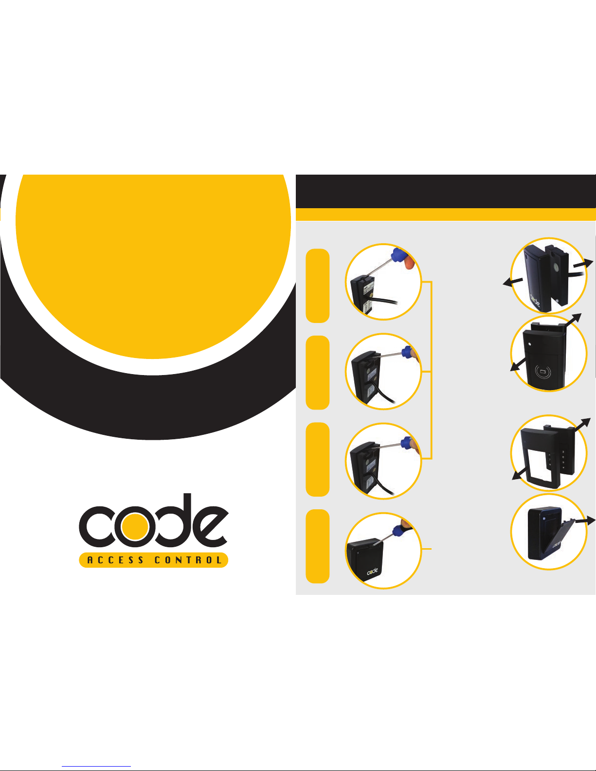
1. INSTALLATION PROCEDURE
CODE-2609CODE-2611
CODE-2621
CODE-2631
To remove the plastic
reader front cover, turn
the reader upside
down and gently
apply a small flat
blade screwdriver to
the lip of the reader
and pull the
screwdriver upwards
until the cover it
partially away from
the reader.
To remove the plastic
reader front cover plate
insert, turn the front of the
reader towards you and
carefully insert a small flat
blade screwdriver to the
top hole of the reader
and pull the screwdriver
upwards until the cover is
comes partially away
from the reader.
Gently pull the plastic cover
away from the main body of
the reader.
Gently pull the plastic
cover away from the main
body of the reader.
STEP 1 STEP 2
Page 2
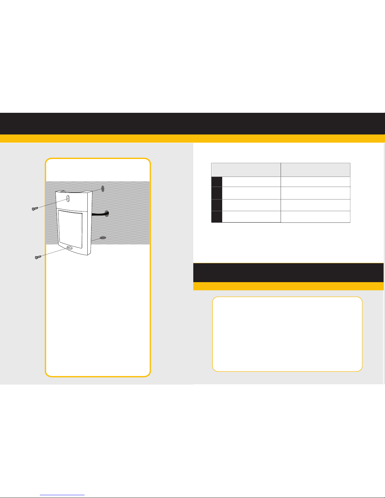
2. ENVIRONMENTAL PARAMETERS
Fixing to a wall
Fixing to a wall for CODE Readers – 2609, 2611 & 2621.
• Drill a small hole in the wall big enough for the reader cable.
• Push the reader cable through the wall and join to the cable
from the CODE Controller.
• Pull the reader cable through the entry hole and then fix and
screw the main body of the reader on to the wall.
• Once the reader is fixed to the wall, refit the reader front cover
on to the reader.
Fixing to a wall for CODE Readers – 2631
• Drill a small hole in the wall big enough for the reader cable.
• Push the reader cable through the wall and join to the cable
from the CODE Controller.
• Pull the reader cable through the entry hole and then fix and
screw the main body of the reader on to the wall.
• Once the reader is fixed to the wall, refit the reader front cover
plate on to the reader.
1
2
3
4
NO
Parameters
Working Voltage
Working Current
Working Temperature
Storage Temperature
10-15V DC
<100mA
-10ºC-+55ºC
10%-90%
Items
Technical
3. READER PARAMETERS
STEP 3
Reader Radio Frequency: 13-56 MHz
Card Identification Mode: MF card
Sensing Distance: MF Card 2 - 10cm
Reader Data Output: Wiegand 26 Bit
Reading Speed: < 0.1s
Diagram shows CODE-2611 for
illustration purposes
Page 3

4. WIRING NOMINATION
+12v
Ground
Data 0
Data 1
LED
Buzzer*
Reader Wire
RED
Black
Green
White
Blue
Yellow
RD+
RD-
Data 0
Data 1
BUZ
BUZ *
*Note
To activate the sounder during the operation of the LED changing to
Green, connect the Yellow Buzzer wire to “BUZ” on the controller.
Colour Controller Connection
Page 4

5.1
For the reader cable connection to the CODE Controller, CAT 5 cable or 8 core
twisted pair cable can be used.
5.2
The reader is normally installed at the right side of the door (outside) at a height
of 1.4m from the floor and 3-5 cm from the door frame, with the exit button
(inside) also 1.4m from the floor
5.3
The reader should not be installed against a metal surface. If this can not be
avoided, either the metal surface should be removed, with only the fixing area
remaining, or an isolation material thicker than 10cm should be placed
between the reader and the metal surface.
5.4
The Controller to reader length should not exceed 60 metres using CAT 5 cable
5.5
Please observe reader power polarity when connecting to the access controller
5. NOTES FOR INSTALLATION
6. INSTRUCTIONS FOR KEYPAD
6.1
The CODE Keypad supports 6-digit number password
6.2
The Reader converts the 6-digit Password number to a 26-bit Wiegand output.
6.3
The user should input the second digit within 2 seconds after inputting the first.
Otherwise the first digit will be deleted and the user has to input the password again.
Page 5

7. FAQ
OTHER PRODUCTS IN THE RANGE
Code
Description
1 or 2 door controller with Ethernet connection
1 or 2 door controller with Serial connection
2 or 4 door controller with Ethernet connection
2 or 4 door controller with Serial connection
5 Amp Power supply in Metal Box Enclosure
Card Distributor
Mifare Card
CODE-ME12
CODE-MS12
CODE-ME24
CODE-MS24
CODE-6800
CODE-FC02
CODE-MF01
What should I do?:
7.1
Real Time Monitoring
If the data displayed on the on the Real Time monitoring is incorrect, please check
the following.
• Check whether the Data transmission connections of DATA 0 and DATA 1 are
correct.
• Check that the distance between the controller and the reader is no longer than
60 metres (Wiegand 26 bit). If so, reduce the distance between the controller and
the reader.
• Check the RD OK (Reader signal OK) LED ok goes green when an ID device is
presented to the reader.
• Check the power on the reader power wires is within 10.5v DC and 12.5v DC.
7.2
If the lock does not operate.
• Check whether the connections of the readers, exit buttons and electric locks are
wired correctly.
• Check if the output of the relay switches and the relay operation LED switches on.
• Check if the power is being switched to the lock.
• If there is no switching of the relay, then check the reader and the wiring.
• Check the access software programming.
7.3
If the Reader does not operate after a power down.
• Please perform a controller download from the CODE Access Software
7.4
When the door can not be opened by reading the card after the power supply
recovered.
• Try performing a full download to continue.
 Loading...