

Page 1
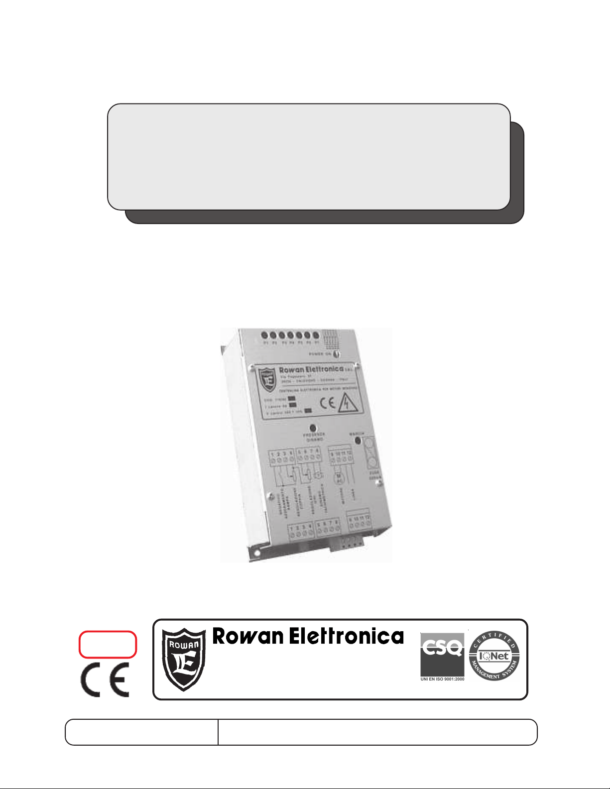
INSTRUCTION MANUAL
CODE 119/92
FOR ASYNCHRONOUS ROWAN SINGLE-PHASE MOTORS with
T ACHOMETER
CONFORMITY
EMC
REV. 6 - Date 21/10/09
ROWAN ELETTRONICA S.R.L. - Via Ugo Foscolo, 20 - 36030 CALDOGNO (VICENZA) ITALY
Motori, azionamenti, accessori e servizi per l'automazione
Via Ugo foscolo, 20 - CALDOGNO - VICENZA - ITALIA
Tel.: 0039 0444 - 905566 - Fax: 0039 0444 - 905593
E-mail: info@rowan.it - WEB-SITE: www.rowan.it
Page 2

INDEX
page
C119/92 Series - Technical characteristics - Standard Conformity 3
Overall dimensions - Working principles 4
Circuit silkscreen, trimmers, micro-switches, leds - terminal board 5
Description of trimmers, microswitches, displays 6
Standard set-up, Characteristics of single-phase motors and power absorbed by brake and fan,
Instructions for the connection of Rowan single - phase motors, Motor service board connection
7
Brake connection, instructions for connection and start-up , E.M.C. standard 8
Connection diagrams, Examples of control terminal board connection 9
Instructions for maintenance of Rowan motors 11-12
Instructions for the replacement of previous drives 13-14
Block diagram 15
Warning !
- ROWAN ELETTRONICA s.r.l. declines any responsibility for any inaccuracies contained in this manual, due to
printing and/or transcription errors. ROWAN ELETTRONICA s.r.l. reserves the right to make any variations that it
considers necessary for better functioning of the product, without prior notification.
- Regarding the data and characteristics mentioned in the manual, a maximum tolerance of 10% has been allowed,
if not otherwise indicated.
- The product guaranty is considered ex-works and is valid 6 months from the date of leaving ROWAN ELETTRONICA
s.r.l.
- The electrical equipment could create dangerous situations for the safety of both personnel and objects; the user
is responsible for the installation of the equipment and for the conformity of the installation with the regulations in force.
- The diagrams contained in this manual are mere examples and should be perfected by the customer according
to their specific needs.
- The equipment must be installed only by qualified personnel, after having read and understood this manual. In
case of doubt, the supplier should be contacted.
ROWAN ELETTRONICA S.R.L. - Via Ugo Foscolo, 20 - 36030 CALDOGNO (VICENZA) ITALY
Page 3

CODE 119/92
DRIVE FOR ASYNCHRONOUS ROWAN SINGLE-PHASE MOTORS
with TACHOMETER
POWER RANGES
This drive is produced in two sizes on the same base:
- C119/92 for the command of Rowan single.phase motors up to 1HP. Provided with 10A protection
fuse.
- C119/92/2 for the command of Rowan single-phase motors up to 2HP. Provided with 20A
protection fuse.
TECHNICAL CHARACTERISTICS
-
product
- Standard supply voltage: 230Vac ±10% 50/60Hz.
- Environmental temperature limit: -5°C +40°C.
- Stocking temperature from -25°C to +70°C.
- Working humidity limit from 5 to 95% (without condensation).
- Preset for ROWAN single-phase motors 2 - 4 - 6 pole, with 10Vdc at 1400rpm (20V at 2800rpm)
tachometer.
- Input/output signals galvanically insulated from high voltage and connectable to PLC, programmable
logics, interface drives, etc.
- Input for tachometer with precision rectifier for functioning in both rotational sense.
- Motor revolution control adjustable through potentiometer (connected at 2 or 3 wires) or 0 /+10Vdc
signal.
- Motor torque limitation internally adjustable through trimmer, or externally through potentiometer
or 0 / +10Vdc signal.
- Input for pure contact (or NPN open collector transistor) for static run/stop command(12Vdc 2mA).
- Internal regulations through trimmer for:
> acceleration/deceleration ramp
> max speed
> minimum speed
> max torque
> minimum torque
> stability (anti-oscillation trimmer)
- Signalling by led illumination of the following functions:
> power on
>tachometer generator presence
> motor run
- Driving circuit protection with 0.5 A fuse (power protection to be performed externally).
- Cage-clamp terminal strip (in type 119/92 2 Hp power terminal strips are screw-clamp type).
- Standard open version with metal support and poly-carbonate cover, protection level IP 20
STANDARD CONFORMITY
Drive Code 119/92 is in conformity with the general IEC EN 60204-1 standard corresponding to the
essential safety requirement of the "Machinery Directive 89/392/CEE", modified by the CEE
Directive 91/368 - 93/44 - 93/68. In particular, regarding the Electro-magnetic Compatibility (EMC)
in industrial environment, drive Code 119/92 is in conformity to the product CEI EN 61800-3
standard, for "VARIABLE SPEED ELECTRICAL DRIVES" if connected to the network through a
filtering device as indicated by diagrams on page 9 and installed as written on page 8.
Ask Rowan El. for choosing the correct anti E.M.I. Filter (ELECTROMAGNETIC INTERFERENCE).
ROWAN ELETTRONICA S.R.L. - Via Ugo Foscolo, 20 - 36030 CALDOGNO (VICENZA) ITALY
Page 4
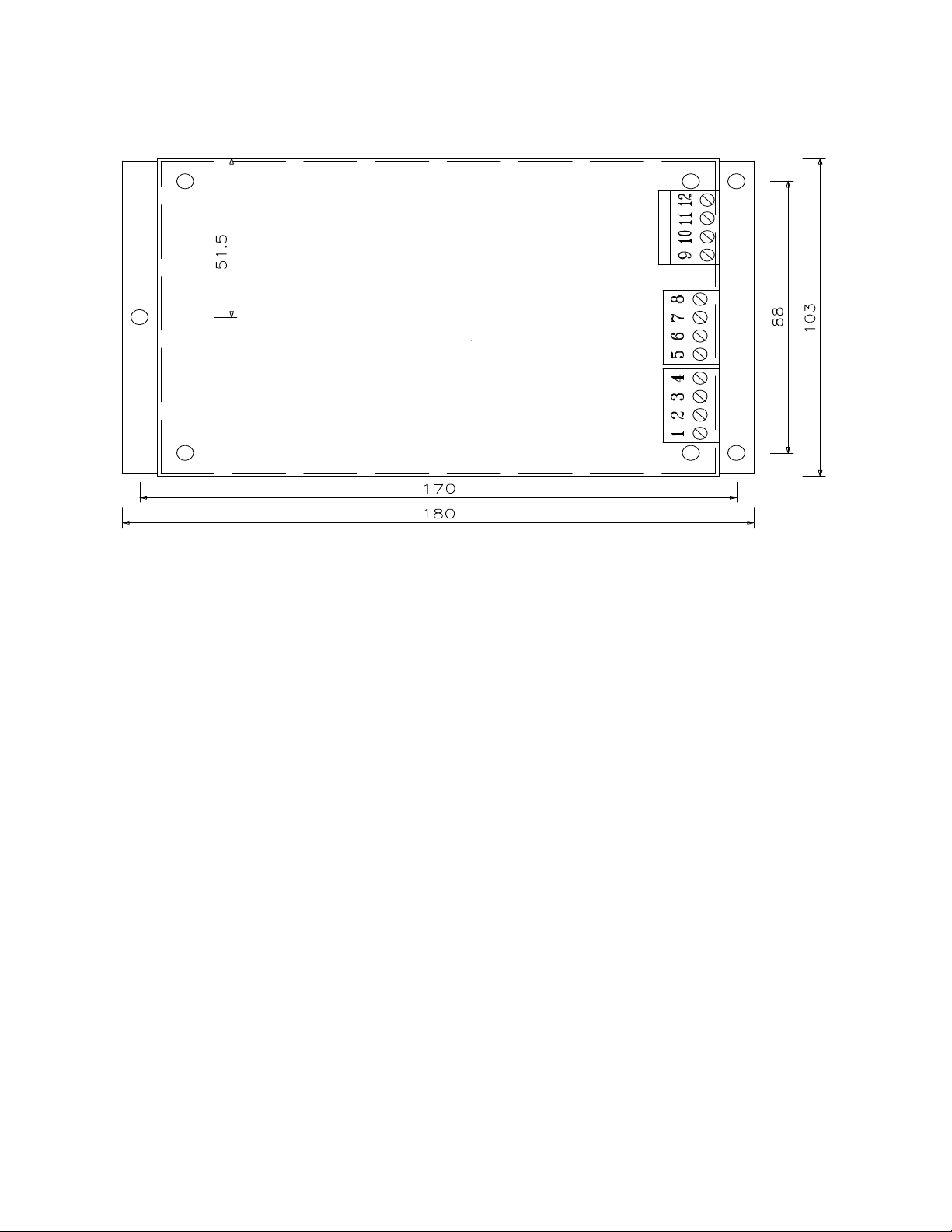
OVERALL DIMENSIONS in mm
Height:
Code 119/92 = 65 mm Code 119/92 - 2HP = 95 mm
WORKING PRINCIPLES
Drive code119/92 is a single-phase voltage regulator with tachometer feedback using controlled
diodes (SCR) driven by a system at phase partialization.
The voltage supplying the motor results from an analog process mantaining constant rotations by
means of the differential control between the real speed reference taken from the tachymeter generator
and the one set by the potentiometer or external analog voltage. The coupling with the asynchronous
single-phase high slip Rowan motor gives a variable speed system extremely silent (Absence of
typical PWM whistle) and uniform, from zero to the maximum motor rounds. The application of
controlled diodes on the power part gives reliability against extravoltages or over-currents. In addition,
it is possible to adjust the acceleration/deceleration ramp upon the application needs; the controlled
acceleration ramp works for moving braking loads or irreversible systems only.
Drive code 119/92 gives the possibility to control the speed/torque of the Rowan single-phase motor;
the torque regulation can be done by limiting the maximum voltage on the motor through internal
trimmer P1 or, externally, through potentiometer or 0/+10Vdc signal; for a more precise control of the
motor torque, it is necessary to let the code 119/92 communicate with other devices working at current
closed loop (ex. code 199/92 or code 268).
ROWAN ELETTRONICA S.R.L. - Via Ugo Foscolo, 20 - 36030 CALDOGNO (VICENZA) ITALY
Page 5
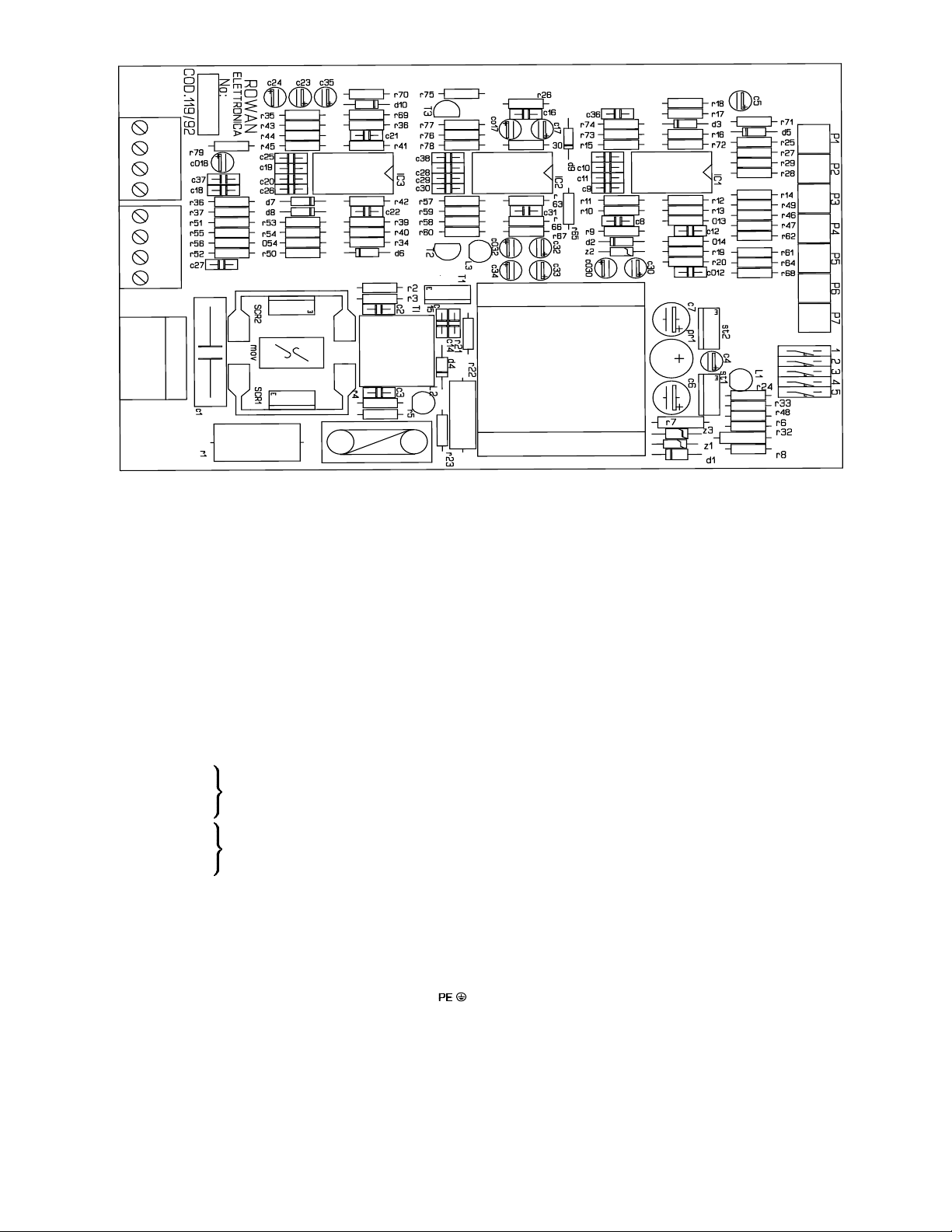
CIRCUIT SILKSCREEN - TRIMMERS, MICRO-SWITCHES, LEDS
DESCRIPTION OF CONNECTION TERMINAL BOARD
1 - 6 -7 ZERO VOLT for input/output signals.
1 - 2 A.R. contact connection (static run consent) or NPN open collector transistor; when open, assents
1 - 3 torque limitation 0 / +10VDC signal input:
1 - 4 +10VDC 3mA reference voltage output for speed and torque (max. 3kohm load) regulation external
1 - 5 speed regulation 0 / +10VDC signal input:
1 = extreme
3 = cursor torque limitation external potentiometer connection
4 = extreme (active with S1 open) R = 10kohm
4 = extreme
5 = cursor speed regulation external potentiometer connection
6 = extreme (active with S3 open) R = 10kohm
For connection of the 2 wire potentiometer (R = 10kohm) close microswitch S3 and use only terminals 5 - 6.
7 - 8 tachogenerator type 20VDC / 2800 rpm input
9 - 10 regulated output for powering starting and power windings of single phase Rowan motor (max 230VAC 8A
acceleration ramp motor rotation up to maximum set speed and causes RUN led illumination. Closed, it
removes voltage from the motor and set acc./dec. ramp to zero.
0VDC = minimum torque / +10VDC maximum torque
potentiometers.
0VDC = zero turns / +10VDC = max speed
for code 119/92 up to 1HP and max 230VAC 15A for code 119/92/2 - 2HP).
11 - 12 power supply 230 VAC ±10% 50/60 Hz. -
ROWAN ELETTRONICA S.R.L. - Via Ugo Foscolo, 20 - 36030 CALDOGNO (VICENZA) ITALY
GROUND CONNECTION.
Page 6

DESCRIPTION OF TRIMMERS
P1 max torque limitation if adjusted counter-clockwise, it limits max voltage to motor windings (active with
microswitch S2 closed).
P2 minimum torque if adjusted clockwise, it increases min voltage to motor windings (active with microswitch
S2 closed).
P3 acceleration/deceleration ramp min 20 mSec, max 8 Sec.
P4 max speed regulates motor max speed with speed regulation potentiometer at maximum and in any case with
input on terminal 5 = +10VDC. Turned clockwise, it increases speed.
P5 min speed regulates motor min speed with speed regulation potentiometer at minimum and in any case with
input on terminal 5 = 0VDC. Turned clockwise, it increases speed.
P6 stability: to be regulated clockwise to stabilise any oscillations in the control of speed if regulation of trimmer
P7 was not sufficient (proportional / integral action).
P7 stability: to be regulated in a counter-clockwise direction to stabilise any oscillations in the control of speed
(integral action).
DESCRIPTION OF MICROSWITCHES
S1 open: activates external torque limitation from potentiometer or from 0+10VDC signal connected to terminal 3
closed: activates board internal torque limitation from trimmer P1
S2 open: cuts out torque limitation
closed: activates torque limitation
S3 open: in case of 3 wire speed regulation potentiometer connection
closed: in case of 2 wire speed regulation potentiometer connection
S4 open: in case of connection to 2 pole motor
closed: in case of connection to 4 pole (or 6 pole) motor. In case of 6 pole motor recalibrate maximum speed
with P4 until the tachogenerator generates a maximum voltage of 6 VDC.
S5 open: in case of maximum precision in controlling speed (minimum shift from loadless to loaded)
closed: enchances prompter response in speed change transients to the detriment of precision (greater shift
from loadless to loaded)
DESCRIPTION OF DISPLAYS
L1 POWER ON: indicates power supply flowing through the board and driving circuit.
L2 RUN: when on indicates that motor rotation has been enabled with the opening of run consent contact (AR)
at terminals 1 - 2. It illuminates in proportion to the voltage to motor windings.
L3 TACHOMETER GENERATOR PRESENCE: when on indicates that motor is rotating and that tachometer
generator voltage is available at terminals 7 -8. Tachometer generator voltage is directly proportional to motor
speed and assumes a value of approximately 20VDC at 2800 tpm.
ROWAN ELETTRONICA S.R.L. - Via Ugo Foscolo, 20 - 36030 CALDOGNO (VICENZA) ITALY
Page 7

STANDARD SET-UP
ROTOM
CEM
PH WK
moNI
A
.DNOCHCNUAL
Fu desaercni(
tadedeeneuqrot
)trats
NAF
REWOP
W
EKARB
REWOP
W
36 51.0 11.0 6.1 )61(21 01 02
17 52.0 81.0 9.1 )52(02 61 02
08 5.0 73.0 1.3 )13(52 81 52
09 1 57.0 6 )05(04 05 03
119/92 drives come out of Rowan labs ready tested and set-up for:
- 4-pole motors with speed regulation by 3-wire potentiometer (min. 0 rpm - max. 1300 rpm);
- torque limitation not active;
- acc/dec ramp: 2 Sec.;
- microswitch S4 closed (all other microswitches open).
SINGLE-PHASE MOTORS CHARACTERISTICS AND POWER ABSORBED BY BRAKE AND COOLING FAN
The capacitor within parentheses increases starting torque by
approx. 20% but cannot be used for continual service; its use is
recommended only for intermittent movements.
The maximum current of Rowan single-phase motors is to be
calculated to an approximate value by multiplying the rated value
by 1.5. The same current can be used during the starting phase
or in cycles that require the use for a period equivalent to a
maximum of 20% of the entire work cycle.
INSTRUCTIONS FOR THE CONNECTION OF SINGLE PHASE ROWAN MOTORS
LAUNCHING WINDING
POWER WINDING
TERMINALS OR CONNECTOR
FOR BRAKE CONNECTION
SERVICE TERMINAL BOARD
POWER TERMINAL BOARD
MOTOR SERVICE BOARD CONNECTION
1-2 TACHOMETER GENERATOR: from these terminals it is possible to have the
voltage of the tachometer generator that is spliced to the motor shaft. It supplies
a direct voltage of 20VDC at 2800RPM that is directly proportional to motor
speed; for this reason, besides being connected to the drive for speed control,
it can be used for analog revolution counters, display counters or other
servomechanisms, provided the overall loading being not lower than 5Kohm
TACHOMETER
GENERATOR
VENTILATOR
THERMIC PROBE
(max tachometer current 5mA). It is always necessary, to avoid interferences,
to connect the tachometer with screened cable.
3-4 VENTILATOR: it is necessary to supply these terminals with 220VAC for the separated ventilation of motor; make sure
that this voltage is present also when the motor is not running, in order to guarantee the max cooling efficiency. As for the
power absorbed by cooling fans, see table on the previous page.
5-6 THERMIC PROBE: it is a N.C. contact which opens when the temperature of motor windings exceeds 150°C, safety
limit corresponding to H class (180°C). It is used as emergency for the switching off of RUN remote control switch. The
max capacity of this contact is 1A - 230VAC. (Rowan motor MEC 63 0,15 HP is not equipped with Thermic Probe; for this
reason terminals 5-6 are not present in its service terminal board).
ROWAN ELETTRONICA S.R.L. - Via Ugo Foscolo, 20 - 36030 CALDOGNO (VICENZA) ITALY
Page 8

BRAKE CONNECTION
On request, ROWAN motors can be provided with
electromagnetic brake. In this case the motor must be
constructed expressly with lengthened motor shaft and
the brake is mounted on the front part, supported by a bell
which reproduces the normal flanging conditions.
There are 2 different types of brakes:
- DIRECT BRAKE: in this case it is necessary to supply the brake to block the motor shaft. This kind of brake is suitable
for precision stops. Its efficiency can be increased by using ROWAN card cod. 210, which oversupplies it at the stop
improving its precision.
- SAFETY SPRING BRAKE: in this case it is necessary to remove supply from the brake to block the motor shaft. It is used
as safety brake in case of lack of main power supply, with suspended loads as overhead travelling cranes, cranes etc.
Both brakes operate with direct voltage 24VDC, and are supplied through the single terminal or connector placed on the
front brake bearing-bell. It is always advisable to connect a diode or a R/C in parallel with the brake, above all when near
to equipments that are particularly sensitive to disturbances. As for the power absorbed by brakes see table on page 3.
In case a transformer with secondary 24VDC is used, it is necessary to insert a levelling condenser C1 dimensioned
for the power of the brake; when the condenser is not present, a transformer with secondary 27 VAC must be used.
INSTRUCTIONS FOR CONNECTION and START-UP
Before powering, connect to the ground and set up the microswitches on the board to suit the desired type of operation:
- 2 or 3 wire speed regulation potentiometer
- inclusion of internal/external torque limitation (see microswitch description)
- 2, 4 or 6-pole motor
In case of a 6-pole single-phase motor recalibrate the maximum speed with trimmer P4 until the tachometer dynamo
generates approx. 5.7 VDC with the speed regulation potentiometer or DC signal at maximum value.
- Before powering, adjust the potentiometer or DC signal for zero speed; at power up the motor must be stationary.
Illumination of led L1 (power on) indicates that power supply is flowing through the driving circuits. Turn potentiometer or
increase DC signal: motor speed should increase or decrease according to the set acceleration/deceleration ramp, while
leds L2 (run) and L3 (tachometer gen. presence) must light up accordingly; progressive illumination of led L2 indicates
the presence of voltage in the motor windings, whereas light-up of L3 indicates that the motor is rotating.
- If the motor suddenly races to maximum speed without following potentiometer regulation, and pilot lamp L3 does not
illuminate, it means that tachometer dynamo voltage is not reaching terminals 7 and 8; when this happens reinspect the
connections.
- Check attainment of maximum speed and, if necessary, fine adjust the maximum value with trimmer P4; be sure not to
exceed the maximum speed as this would cause the motor to overheat even when loadless; when this happens regulate
P4 until motor consumption equals the value measured at an intermediate speed. In any case check that motor
consumption (measured at power supply line) conforms with the rated value. If during motor operation oscillations take
place due to a particular type of load or due to mechanical transmission, these may be suppressed by regulating trimmer
P7 clockwise; if regulation of P7 were not enough, also regulate trimmer P6 counter-clockwise. To prompt and smoothen
motor response you may close microswitch S5.
Drive 119/92 is provided with a 0,5A protection fuse only for driving circuit; provide external power protection through a
10A fuse for drive 119/92 and 20A fuse for drive 119/92-2HP. Use a shielded cable for control connections (potentiometer,
tachometer generator) especially if they are long stretches or run close to power cables; connect cable braiding to ground
and not to the circuit negative, and only at one cable terminal; the board negative must also not be connected to ground;
at any rate, do your best to avoid routing near power cables or large transformers.
Use relays with contacts for low current for the switching of DC signals on the control terminal panel, and avoid the use
of electromagnetic switch auxiliary contacts for these types of operations.
Drives 119/92 series operate efficiently with panel temperatures ranging from -5°C to +40°C; temperatures outside this
range may give rise to faulty operation, speed control drifts and, if temperatures are particularly high, breakdown. Thus place
the boards far from heat sources and provide adequate ventilation to the panel if the environment is subject to high
temperatures.
ISTRUCTIONS FOR THE CORRECT INSTALLATIONS AS PER THE ELECTRO-MAGNETIC COMPATIBILITY
STANDARDS (E.M.C.)
Drive Code 119/92 must be supplied through anti E.M.I. filter as indicated in the connection diagrams on page 11; if more
C119/92 drives are installed into the same cabinet we can use a unique filter dimensioned for the total supply currents.
In addition, it is necessary to use a shielded cable to connect the commands (potentiometer, tachometer) especially when
distances are long and we are near to power cables; the cable sleeve must be connected to ground (not to the negative
of the circuit) to one end only; do not connect the negative of the drive to ground; avoid, in any case, the proximity to power
cables or big transformers. Avoid, finally, to create ground loops.
ROWAN ELETTRONICA S.R.L. - Via Ugo Foscolo, 20 - 36030 CALDOGNO (VICENZA) ITALY
Page 9

CONNECTION DIAGRAMS
Application
MOTOR POWER TERM. BOARD
Diagram No. 1
RIGHT
ROTATION
SENSE
MOTOR POWER TERM. BOARD
LEFT ROTATION
SENSE
CODE 119/92
SPEED REG.
CODE 119/92
SPEED REG.
TACHOMETER
GENERATOR
TACHOMETER
GENERATOR
MAINS LINE
MAINS LINE
This is the basic schematic
diagram for drive 119/92
connection; the two individual
diagrams show how to manually
invert the rotation sense of the
motor by operating on power
connections (tachometer
dynamo polarity does not need
to be inverted); speed regulation
is by potentiometer connected
with 3 wires which ensures linear
regulation of speed with respect
to potentiometer rotation,
whereas torque adjustment is
excluded. In this case (if the motor
is a 4-pole one) only microswitch
S4 is to be closed.
Application
MOTOR POWER TERM. BOARD
CODE 119/92
Diagram No. 2
220 VAC
TACHOMETER
SPEED REG.
GENERATOR
In this case 119/92 drives the single-phase motor in both rotation senses; rotation sense is changed by inverting the starting
winding with respect to power winding.
Set up board 119/92 as shown in schematic diagram No. 1.
EXAMPLES OF HOW TO CONNECT THE CONTROL TERMINAL BOARD
Connection of 2-wire speed regulating potentiometer:
Should you need to use the 2-wire speed regulating potentiometer (as for instance
SPEED REG.
when replacing Rowan drives of previous manufacture such as old C119) close
TACHOMETER
GENERATOR
microswitch S1 and connect a 10 KOhm potentiometer; speed regulation with 2wire potentiometer is not very linear with respect to its rotation.
Selection of different speeds with more potentiometers in parallel:
Two or more potentiometers can be connected in parallel making sure that the
overall resistance between terminals 4 and 6 is not lower than 3 KOhm.
Motor torque limitation through external potentiometer:
MAINS LINE
TACHOMETER
GENERATOR
The potentiometer value has not to load the voltage reference of +10Vdc on terminal
4 (R= 3Kohm including the value of the potentiometer); in this case close microswitch
S2 and it is possible to limit the regulation range of the potentiometer by using
trimmer P1 (max.) and P2 (min.). If maximum torque internal limitation were enough,
the external potentiometer can be omitted: in this case close microswitch S1 and
limit torque by regulating trimmer P1.
Speed/torque control from analog signal 0/+10VDC:
In code 119/92 speed and torque regulations, in addition to the conventional
manual potentiometer, can be performed by applying a 0/+10 VDC signal; depending
on requirements, this signal can be picked up by Rowan interface boards of by other
commercial equipment as PLCs, LOGIC BOARDS, COMPUTERS, etc.; the
connection can be carried out directly because the board inputs are galvanically
insulated from high voltage. Input impedance is 100 KOhm. Close microswitch S2.
ROWAN ELETTRONICA S.R.L. - Via Ugo Foscolo, 20 - 36030 CALDOGNO (VICENZA) ITALY
TORQUE
LIMITATION
TORQUE SET
0/10VDC
INPUT
SPEED
REG.
SPEED SET
0/10VDC
INPUT
TACHOMETER
GENERATOR
TACHOMETER
GENERATOR
Page 10

Static run:
When the single-phase motor is used in only one direction, and frequent run and
stop operations have to be performed, it is convenient to keep the power supply
electromagnet switch excited and to enable static motor rotation by opening contact
AR connectable to terminals 1-2.
- By opening contact AR, the motor follows the acceleration ramp up to the maximum
speed set and with a ramp time that is adjustable by trimmer P3.
- Closure of contact AR immediately removes voltage, zero-sets the ramp and
switches off RUN led L2.
If motor run/stop were necessary with acceleration and deceleration ramps without
immediately removing voltage from the motor in its stopping phase, perform the
following operations:
- disconnect terminal clamp 5 from the voltage reference to cause the motor to
decelerate to zero revs (or at a minimum speed calibrated with P5);
- connect terminal clamp 5 to the voltage reference to cause the motor to accelerate
to the maximum speed set.
Speed variations are conditioned by the acceleration/deceleration ramp set with
trimmer P3; the controlled deceleration ramp operates with motors applied to
braking loads or irreversible systems, but it is inefficient with inertial type loads.
STATIC RUN
SPEED
REG.
TACHOMETER
GENERATOR
ROWAN ELETTRONICA S.R.L. - Via Ugo Foscolo, 20 - 36030 CALDOGNO (VICENZA) ITALY
Page 11

MAINTENANCE INSTRUCTIONS FOR HIGH SLIP ROWAN MOTORS
“HIGH SLIP ROWAN” type motors are specifically designed to be controlled by tachometrically controlled
electronic circuits and their intrinsic characteristics are especially suited to support repeated start-up surges and
dynamic braking.
Since they are brushless their maintenance is reduced to a bare minimum and normally merely concerns the
bearings and changing the tachometric dynamo, which nevertheless may be necessary after a minimum of 5000
work hours.
Changing bearings or tachometric dynamo
If the motor has to be dismantled to change the bearings, proceed as follows:
1- remove the screws on the rear fan housing or scroll fan and slide it out, disconnecting the wires on the service
terminal block
2- take out the tachometric dynamo
3- slide the stays out and remove the rear housing
4- remove the front housing that comes out followed by the rotor attached to it
5- if necessary remove the front bearing, the dust guard screws and remove the snap ring (if mounted) on the shaft
6- slide the shaft out of the bearing
7- remove the snap ring (if mounted) that holds the bearing on the housing
8- slide off the bearing and replace it with an equivalent type - Z C3 version lubricated with high temperature stringy
grease
9- the rear bearing must be type 2RS C3.
If necessary, replace the tachometric dynamo while assembling the motor.
Calibration of the air gap on the spring or direct brake
If a spring brake is mounted and the air gap requires calibration, proceed as follows:
1- remove the bolts coupling the motor to the brake hub
2- slide off the hub and brake off the shaft
3- remove the screws attaching the brake to the hub,
4- disconnect the brake cable from the terminal block
5- slide the brake off the hub.
At this stage the calibration can be made by adjusting the 3 bolts until an air gap between 0.2 and 0.3mm is
obtained. If the brake mounts a dustproof filter, remove it to access the calibration bolts.
The spring brake is supplied with the maximum braking torque, which can be reduced by unscrewing the specific
crown to a maximum of 40%, always making sure not to unscrew it right out.
If the direct brake has been mounted, there is no need to dismantle it, just control the air gap (maximum 0.3 mm)
with a calliper through the side vents and if necessary correct it by slackening the grubscrew on the brake hub.
Rowan motors require continuous ventilation and therefore it is essential that all the internal and external air
passages in the motor are not blocked by foreign bodies and moreover an adequate air change must be provided.
In particularly aggressive environments Rowan motors, which are normally IP 23, can mount a dustproof filter up
to an IP 54 protection rating, and especially in this case frequent controls have to be made to ensure the filter is
clean and the fan is in perfect working order.
Greater protection ratings can be obtained, up to IP 55, providing a completely closed motor down-rated by 50%.
The motor has a heat sensor in the windings that is calibrated to trip at 150°C (Rowan motor windings are class
H with a working temperature limit of 180°C).
The sensor gives a normally closed contact that opens at 150°C and has to be used to cut of the motor power
by a suitable relay switch in the event of an overload. The sensor will take a maximum load of 1A at 230VAC.
If the overload probe trips, check:
- the fan operation
- a free air flow
- the motor absorption, if over the ID plate data, may be caused by excessive load or worn bearings.
ROWAN ELETTRONICA S.R.L. - Via Ugo Foscolo, 20 - 36030 CALDOGNO (VICENZA) ITALY
Page 12

The stator winding is for a three or single phase asynchronous motor, particularly well built in class H insulation.
If necessary it can be carried out by any coil winder so long as the winding data is respected, which is available
from our technical office.
1 > FRONT SHIELD (aluminium), which can be supplied in the following versions
- FLANGED for B5, B3/B5 motors or with auxiliary electromagnetic brake motors;
- FOOTED for B3 and B3/B5 motors.
2 > FRONT AND REAR BEARING in C3 2RS.
3 > SEEGER RING (63, 71 and 80 motors have this part only if equipped with brake).
4 > CONIC DEFLECTER (aluminium).
5 > MOTOR SHAFT (C40 Steel) normally supplied in the following versions:
- STANDARD SHAFT for B3 or B5 motors without brake; LONG SHAFT for motors equipped with brake; REDUCED SHAFT
(hardened steel) with reduced output dimensions.
6 > MASSIVE ROTOR (iron) with cavities for air cooling passage.
7 > STATOR FRAME composed by: EXTERNAL RIBBED FRAME with the housing for power terminal board (Aluminium
F91); STATOR CORE
(iron); STATORIC WINDING (copper).
8 > POWER TERMINAL BOARD for the connection of motor windings, with relative terminal board covering.
9 > FEET for B3 or B3/B5 versions
10 > THERMIC SENSOR INSIDE WINDINGS
11 > COMPENSATOR RING
12 > REAR RING for rear bearing housing.
13 > SERVICE TERMINAL BOARD for tachometer generator, ventilator and thermic sensor connection.
14 > TACHOMETER GENERATOR TYPE 24VDC/2800 rpm, IP54, with relative joints; it can be supplied in 2 versions:
- DIN55: for motors MEC 63, 71, 80, 90, 100
- DIN70: for motors from MEC 112 to MEC 200L
15 > INDEPENDENT VENTILATOR, for motor cooling, of 2 possible types: Axial and Scroll.
16 > VENTILATOR COVERING for axial fan; not present on motors with scroll fan where there is the fan support only.
17 > ELECTROMAGNETIC BRAKE which can be supplied in the following 2 types: spring/safety brake (normally closed)
and direct brake (normally open); the spring/safety brake can be equipped on request with a lever for manual
opening.
18 > FLANGED DISC of BRAKE BEARING BELL (separated from the brake bearing bell only on motors Mec 90, 100, 112
and 112L).
19 > BRAKE BEARING BELL (aluminium).
20 > REAR SPACER.
21 > TACHOMETER JOINT.
ROWAN MOTORS OPERATE CORRECTLY AT AMBIENT TEMPERATURES BETWEEN -15°C AND +40°C;
HIGHER TEMPERATURES CAN CAUSE OPERATING FAULTS AND, IF VERY HIGH, BREAKDOWNS.
THEREFORE, IT IS RECOMMENDED TO KEEP THEM AWAY FROM HEAT SOURCES AND GUARANTEE A
MINIMUM AIR CHANGE.
ROWAN ELETTRONICA S.R.L. - Via Ugo Foscolo, 20 - 36030 CALDOGNO (VICENZA) ITALY
Page 13

INSTRUCTIONS FOR THE REPLACEMENT OF PREVIOUS DRIVES WITH ACTUAL TYPE CODE 119/92
Drive code 119/92 replaces previous drives for the Rowan single phase motors type code 119 and code 120/121.
Remember that in any case code 119/92-2HP board is necessary for the single phase motor 2HP Mec 100.
Replacing drive 119 with drive 119/92:
With regard to power connections:
the wires previously connected to terminals 7 and 8 are to be shifted to terminals 11 and 12 of the code 119/92,
whereas the wires connected to terminals 5 and 6 are to be shifted to terminals 9 and 10.
With regard to control connections:
the tachometer wires that were previously connected to terminals 3 and 4 are to be connected to terminals 7 and
8 of the code 119/92, whereas potentiometer wires as follows: P- (OV) connected to terminal 2 is to be shifted to
terminal 6, and P+ connected to terminal 1 is to be shifted to terminal 5 of the code 119/92. For functioning as old
card cod. 119, microswitch S3 must be closed.
With new drive C119/92, speed regulation with 2 wire potentiometer is not linear but according to an exponential
curve which presents strong variations at slow speed and small variations at high speed. If one wishes to avoid this
behaviour and obtain a variation directly proportional to potentiometer variation, it is necessary to connect speed
potentiometer with 3 wires as indicated in connection diagram of code 119/92 and open microswitch S3.
With regard to control wires connected to the lateral terminal strip of code 119:
- the wire connected to terminal NEG is to be shifted to terminal 1 of the code 119/92
- the wire connected to terminal AR is to be shifted to terminal 2 of the code 119/92
- the wire connected to terminal INV.TACH. is to be omitted (not necessary for the C119/92)
- the resistor connected to terminal REG. COPPIA must be eliminated.
Close microswitch S1 (for the other microswitches refer to the section containing the description of the
microswitches).
If a potentiometer is connected to torque regulation terminals, reconnect it to code C119/92 with 3 wires to terminals
1 3 4 as from electrical drawing; in this case microswitch S2 must be closed.
The circled numbers in the electrical drawing designate the terminals in the code C119/92.
Reg. Coppia = Torque Regulation
Reg. Giri = Speed Regulation
Tachim.= Tachometer Generator
Linea = Mains Line
Negativo = Negative
Azz. Rampa = Ramp to zero setting
Inv. Tach. = Tachometer Inversion
ROWAN ELETTRONICA S.R.L. - Via Ugo Foscolo, 20 - 36030 CALDOGNO (VICENZA) ITALY
Page 14

Replacing drive C120/121 with drive C119/92
For the power connections proceed as follows:
the wires that were connected to the terminals 1 and 2 are to be shifted to terminals 11 and 12 of C119/92, whereas
the wires connected to terminals 3 4 5 6 7 8 related to the capacitor and power and launching windings are to be
reconnected together as shown in the schematic.
For the control connections proceed as follows:
the tachometer wires that were connected to terminals 9 and 10 are to be connected to terminals 7 and 8 of C119/92,
whereas the potentiometer wires as follows: P-(OV), connected to terminal 11, must be shifted to terminal 6,
whereas P+, connected to terminal 12, must be shifted to terminal 5 of C119/92.
For control wires connected to lateral terminal strip M2 of board C120/121 proceed as follows:
shift the wire connected to terminal NEG to terminal 1 of C119/92;
shift the wire connected to terminal AR to terminal 2 of C119/92;
exclude the wire connected to terminal INV. TACH. since it is unnecessary for C119/92;
connect wire connected to terminal DECEL to terminal 5 of C119/92.
Close microswitch S1 (for other microswitches refer to the paragraph describing the microswitches).
If a potentiometer is connected to terminal board M4 for torque limitation, you should reconnect it to terminals
1 3 4 of code 119/92 with 3 wires as illustrated in the schematic diagram; in this case close microswitch S2.
The circled numbers in the schematic refer to the terminals on C119/92.
Reg. Coppia = Torque Regulation
Reg. Giri = Speed Regulation
Tachim.= Tachometer Generator
Linea = Mains Line
Negativo = Negative
Azz. Rampa = Ramp to zero setting
Inv. Tach. = Tachometer Inversion
Decel = Deceleration
ROWAN ELETTRONICA S.R.L. - Via Ugo Foscolo, 20 - 36030 CALDOGNO (VICENZA) ITALY
Page 15

BLOCK DIAGRAM
ROWAN ELETTRONICA S.R.L. - Via Ugo Foscolo, 20 - 36030 CALDOGNO (VICENZA) ITALY
Page 16

CONFORMITY
EMC
ROWAN ELETTRONICA S.R.L. - Via Ugo Foscolo, 20 - 36030 CALDOGNO (VICENZA) ITALY
Motori, azionamenti, accessori e servizi per l'automazione
Via Ugo foscolo, 20 - CALDOGNO - VICENZA - ITALIA
Tel.: 0039 0444 - 905566 - Fax: 0039 0444 - 905593
E-mail: info@rowan.it - WEB-SITE: www.rowan.it
 Loading...