

Page 1
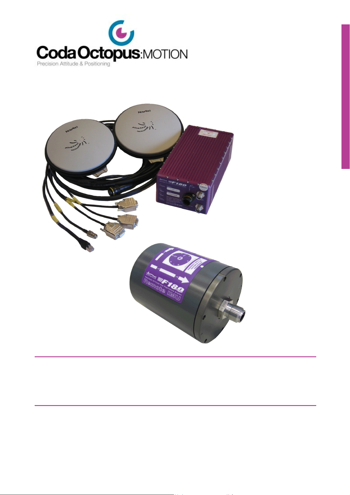
/F180R series
very accurate positioning
and motion data
™
F180R series
User & Reference Guide
Copyright © 2015 Coda Octopus Products Ltd
Version: 2.0.0
Page 2

This guide describes the installation and
configuration of the F180R™ series hardware
and software developed by CodaOctopus that
allows to produce highly accurate positioning
and motion data in the most dynamic offshore
conditions.
™
F180R series
User & Reference Guide
Page 3

F180R MOTION Sensor User and Reference Guide
Copyright © 2015 Coda Octopus Products Ltd
All rights reserved. No part of this manual, including the products and software described in it, may be
stored in a retrieval system, transmitted, or reproduced by any means, including, but not limited to
photocopy, photograph, digitizing, or otherwise - without the written permission of the publisher.
Coda®, Octopus®, F180®, F180R™, F170™ and F175™ are registered trademarks (Reg. U.S Pat & TM Off) or
trademarks of Coda Octopus Group Inc.
Other products that are referred to in this document may be either trademarks and/or registered
trademarks of the respective owners. The publisher and the author make no claim to these trademarks.
Specifications and information contained in this manual are furnished for informational use only, and
are subject to change at any time without notice, and should not be construed as a commitment by Coda
Octopus Products. Coda Octopus Products assumes no responsibility or liability for any errors or
inaccuracies that may appear in this manual, including the products and software described in it.
While every precaution has been taken in the preparation of this document, the publisher and the
author assume no responsibility for errors or omissions, or for damages resulting from the use of
information contained in this document or from the use of programs and source code that may
accompany it. In no event shall the publisher and the author be liable for any loss of profit or any other
commercial damage caused or alleged to have been caused directly or indirectly by this document.
Version: 2.0.0 (16/06/2015)
Page 4

Table of Contents
Contents
4
Chapter 1 Export Policy
Chapter 2 Introduction
2.1 General Description
2.2 Warranty
2.3 Calibration
................................................................................................................................... 12
Inertial Measurement Unit 2.1.1
GNSS System 2.1.2
Software 2.1.3
................................................................................................................................... 14
................................................................................................................................... 14
......................................................................................................................................................... 13
......................................................................................................................................................... 13
......................................................................................................................................................... 13
Chapter 3 Hardware
3.1 Communication
3.2 Technical Specification
3.3 Hardware Installation
3.4 Measure Installation Parameters
................................................................................................................................... 16
Ethernet 3.1.1
Serial Outputs 3.1.2
3.1.2.1
3.1.2.2
3.1.2.3
3.1.2.4
3.1.2.5
3.1.2.6
RTK and Differential Corrections 3.1.3
PPS 3.1.4
................................................................................................................................... 30
Model Specifications 3.2.1
Interfaces 3.2.2
Reference Frames 3.2.3
................................................................................................................................... 34
Component Identification 3.3.1
Antenna Installation 3.3.2
IMU Installation 3.3.3
................................................................................................................................... 41
IMU Orientation 3.4.1
Antenna Offset 3.4.2
Antenna Separation 3.4.3
......................................................................................................................................................... 16
......................................................................................................................................................... 17
MCOM
NMEA
TSS1
TSS HHRP
EM1000 (Tate-Bryant)
EM3000 (Tate-Bryant)
.................................................................................................................................................. 18
.................................................................................................................................................. 18
GGA
GGK
GSA
GSV
GST
HDT
PASHR
PPS
PRDID
PTCF
RMC
ROT
UTC
VTG
ZDA
......................................................................................................................................................... 29
......................................................................................................................................................... 30
......................................................................................................................................................... 31
......................................................................................................................................................... 32
......................................................................................................................................................... 33
......................................................................................................................................................... 34
......................................................................................................................................................... 36
......................................................................................................................................................... 40
......................................................................................................................................................... 42
......................................................................................................................................................... 43
......................................................................................................................................................... 44
........................................................................................................................................... 18
........................................................................................................................................... 19
........................................................................................................................................... 20
........................................................................................................................................... 21
........................................................................................................................................... 21
........................................................................................................................................... 22
........................................................................................................................................... 22
........................................................................................................................................... 22
........................................................................................................................................... 23
........................................................................................................................................... 23
........................................................................................................................................... 25
........................................................................................................................................... 26
........................................................................................................................................... 26
........................................................................................................................................... 26
........................................................................................................................................... 27
.................................................................................................................................................. 27
.................................................................................................................................................. 28
.................................................................................................................................................. 28
.................................................................................................................................................. 29
9
11
16
Copyright © 2015 Coda Octopus Products Ltd
F180R MOTION Sensor User and Reference Guide
Page 5

Contents
5
Antenna Orientation 3.4.4
Remote Lever Arms 3.4.5
3.5 Communication
................................................................................................................................... 46
Ethernet 3.5.1
Serial Outputs 3.5.2
3.5.2.1
3.5.2.2
......................................................................................................................................................... 45
......................................................................................................................................................... 45
......................................................................................................................................................... 47
......................................................................................................................................................... 48
MCOM
NMEA
GGA
GGK
GSA
GSV
GST
HDT
PASHR
PPS
PRDID
PTCF
RMC
ROT
UTC
VTG
ZDA
3.5.2.3
3.5.2.4
3.5.2.5
3.5.2.6
TSS1
TSS HHRP
EM1000 (Tate-Bryant)
EM3000 (Tate-Bryant)
RTK and Differential Corrections 3.5.3
PPS 3.5.4
......................................................................................................................................................... 60
......................................................................................................................................................... 61
.................................................................................................................................................. 49
.................................................................................................................................................. 49
........................................................................................................................................... 49
........................................................................................................................................... 50
........................................................................................................................................... 51
........................................................................................................................................... 51
........................................................................................................................................... 52
........................................................................................................................................... 53
........................................................................................................................................... 53
........................................................................................................................................... 53
........................................................................................................................................... 54
........................................................................................................................................... 54
........................................................................................................................................... 55
........................................................................................................................................... 56
........................................................................................................................................... 57
........................................................................................................................................... 57
........................................................................................................................................... 57
.................................................................................................................................................. 58
.................................................................................................................................................. 59
.................................................................................................................................................. 59
.................................................................................................................................................. 60
Chapter 4 Operation
4.1 Quick Start
4.2 Power-on the System
4.3 Calibration
................................................................................................................................... 63
................................................................................................................................... 63
................................................................................................................................... 65
Pre-Calibration Checks 4.3.1
Calibration Procedure 4.3.2
Calibration Specification 4.3.3
Invalid Calibration 4.3.4
......................................................................................................................................................... 65
......................................................................................................................................................... 66
......................................................................................................................................................... 68
......................................................................................................................................................... 69
Chapter 5 Software
5.1 Installation / Uninstallation
5.2 Main Interface
................................................................................................................................... 72
Software Installation 5.1.1
Software Uninstallation 5.1.2
......................................................................................................................................................... 72
......................................................................................................................................................... 73
................................................................................................................................... 74
Ribbon Bar Tabs 5.2.1
5.2.1.1
......................................................................................................................................................... 74
Data Source - Ethernet
.................................................................................................................................................. 75
Ethernet Source - Live Tab
........................................................................................................................................... 76
RD Files
Change IP Address
Update Firmware
Rebroadcast MCOM
Calibration
........................................................................................................................................... 83
.................................................................................................................................................. 85
.................................................................................................................................................. 87
5.2.1.2
5.2.2.1
Ethernet Source - Logging Tab
Data Source - Replay
Real Time Data 5.2.2
......................................................................................................................................................... 86
Setup Real Time Data Display
System Status 5.2.3
......................................................................................................................................................... 88
63
72
...................................................................................................................................... 76
...................................................................................................................................... 77
...................................................................................................................................... 78
...................................................................................................................................... 80
...................................................................................................................................... 80
Copyright © 2015 Coda Octopus Products Ltd
F180R MOTION Sensor User and Reference Guide
Page 6

Contents
6
Message Log 5.2.4
System Indicator 5.2.5
5.3 MOTION Settings Wizard
................................................................................................................................... 96
Introduction 5.3.1
Orientation 5.3.2
Advanced Orientation 5.3.3
Primary Antenna Mounting 5.3.4
Secondary Antenna 5.3.5
Remote Lever Arms 5.3.6
Output Frame of Reference 5.3.7
Correction Type 5.3.8
Altitude 5.3.9
GNSS Environment 5.3.10
Outputs 5.3.11
Advanced Options 5.3.12
Upload Settings 5.3.13
Save Wizard Settings 5.3.14
Finish 5.3.15
5.4 Motion Data
5.5 Diagnostics
................................................................................................................................... 112
................................................................................................................................... 113
Graphical QC 5.5.1
Heading Initialisation 5.5.2
Connection Properties 5.5.3
System Properties 5.5.4
Help About 5.5.5
5.6 iHeave
................................................................................................................................... 123
Description 5.6.1
iHeave Data Files 5.6.2
iHeave Data Logging 5.6.3
iHeave Status Area 5.6.4
iHeave Alarm Setup 5.6.5
iHeave Alarm Log 5.6.6
......................................................................................................................................................... 95
......................................................................................................................................................... 96
......................................................................................................................................................... 97
......................................................................................................................................................... 98
......................................................................................................................................................... 98
......................................................................................................................................................... 100
......................................................................................................................................................... 101
......................................................................................................................................................... 102
......................................................................................................................................................... 103
......................................................................................................................................................... 103
......................................................................................................................................................... 106
......................................................................................................................................................... 107
......................................................................................................................................................... 108
......................................................................................................................................................... 109
......................................................................................................................................................... 110
......................................................................................................................................................... 111
......................................................................................................................................................... 112
......................................................................................................................................................... 114
......................................................................................................................................................... 116
......................................................................................................................................................... 119
......................................................................................................................................................... 119
......................................................................................................................................................... 122
......................................................................................................................................................... 123
......................................................................................................................................................... 124
......................................................................................................................................................... 125
......................................................................................................................................................... 127
......................................................................................................................................................... 128
......................................................................................................................................................... 129
Chapter 6 Appendices
6.1 Technical Specification
6.2 Inertial Attitude and Position System Theory
6.3 Rotation Convention
6.4 Troubleshooting
................................................................................................................................... 131
Physical 6.1.1
Electrical 6.1.2
Performance 6.1.3
Environmental 6.1.4
Data Logging Rate & Latency 6.1.5
Antenna Cable 6.1.6
......................................................................................................................................................... 131
......................................................................................................................................................... 132
......................................................................................................................................................... 132
......................................................................................................................................................... 134
......................................................................................................................................................... 134
......................................................................................................................................................... 134
................................................................................................................................... 135
Global Positioning System (GPS) 6.2.1
Inertial Navigation System (INS) 6.2.2
GPS-INS Integration 6.2.3
......................................................................................................................................................... 135
......................................................................................................................................................... 138
......................................................................................................................................................... 138
................................................................................................................................... 139
................................................................................................................................... 140
System Troubleshooting 6.4.1
6.4.1.1
6.4.1.2
6.4.1.3
6.4.1.4
Network Troubleshooting 6.4.2
6.4.2.1
6.4.2.2
6.4.2.3
......................................................................................................................................................... 140
Shock Watch
Antenna
Differential / RTK Correction Input
System Operation
Physical Connection
PC LAN Connection
Testing The Network Connection
.................................................................................................................................................. 140
.................................................................................................................................................. 140
.................................................................................................................................................. 142
.................................................................................................................................................. 142
......................................................................................................................................................... 143
.................................................................................................................................................. 144
.................................................................................................................................................. 144
.................................................................................................................................................. 146
131
Copyright © 2015 Coda Octopus Products Ltd
F180R MOTION Sensor User and Reference Guide
Page 7

Contents
7
6.4.2.4
6.4.2.5
6.5 System Dimensions
6.6 Measure Installation Worksheet
6.7 Corrosion Prevention
................................................................................................................................... 149
................................................................................................................................... 156
................................................................................................................................... 156
Changing the IP Address
Network Q & A
F180R Reference Point 6.5.1
Antenna Reference Points 6.5.2
.................................................................................................................................................. 147
.................................................................................................................................................. 148
......................................................................................................................................................... 153
......................................................................................................................................................... 153
Index
158
Copyright © 2015 Coda Octopus Products Ltd
F180R MOTION Sensor User and Reference Guide
Page 8

Chapter
1
Export Policy
Page 9

1 Export Policy
The F180R System Precision Attitude and Positioning System is subject to Export control under
the dual-use item list. Dual-use items are goods, software, technology, documents and
diagrams which can be used for both civil and military applications. It is important when
exporting a F180R System that you always keep a full record of all export destinations, dates
and export documents.
This document aims to provide basic guidance and advice for all users and includes links to
further sources of information where required.
USA
In the US, the F180R System is export controlled under ECCN: 7A103a1 of the Commerce
Control List (CCL) (Supplement No. 1 to Part 774 of the EAR). The Department of Commerce’s
Bureau of Industry and Security (BIS) is responsible for implementing and enforcing the Export
Administration Regulations (EAR).
For further information in the USA visit: http://beta-www.bis.doc.gov/index.php/licensing/
commerce-control-list-classification/export-control-classification-number-eccn
UK and European Union
The main legal basis for controls on dual-use goods is the European Union Dual-Use Regulation
(Council Regulation (EC) No 428/2009 and associated legal amendments). This legislation is
directly applicable in all EU countries, including the UK.
Export Policy
9
The F180R System is restricted under entry 7A103a1 of the EU Dual-Use List and the UK
Consolidated list.
From the UK, the F180R System may be exported:
Within the EU providing that export documents state that the items require a licence if
exported outside the EU and keep appropriate records.
To CGEA countries: Australia, Canada, Japan, New Zealand, Norway, Switzerland and USA
providing according registration has been done and records are kept
To other destinations by applying for a Standard Individual Export Licence
To other destination by using OGELs (Open General Export Licence). They remove the
need to apply for a Standard Individual Export Licence providing a registration has been
done and are subject to conditions. More information available at: https://www.gov.uk/
dual-use-open-general-export-licences-explained
There are also a number of countries where trade embargoes are imposed. These are
constantly changing. For further information on embargoes please visit: https://www.gov.uk/
current-arms-embargoes-and-other-restrictions
For further information in the UK visit: https://www.gov.uk/uk-strategic-export-control-lists-
the-consolidated-list-of-strategic-military-and-dual-use-items
The information contained herein is provided for guidance only. CodaOctopus believes this
information to be correct as of October 2012; however, it is the sole responsibility of the
exporter to ensure that they comply with Export Regulations within the country of export.
CodaOctopus accepts no responsibility for any failure to comply with regulations.
Please contact sales@codaoctopus.com for further details and assistance with export
guidelines.
Copyright © 2015 Coda Octopus Products Ltd
F180R MOTION Sensor User and Reference Guide
Page 10

Chapter
2
Introduction
Page 11

2 Introduction
WARNING: Although selected for their ruggedness, the solid–state accelerometers
and rate sensors used in the IMU are susceptible to excessive shock and vibration.
Refer to the environmental specifications for details. Treat the IMU with care when
you handle it—store it in the transit case until you are ready to install it. Never drop
the IMU or subject it to shocks. A 'Shockwatch' label attached to the IMU casing will
show a red central vial if the unit is subjected to severe shock. If this occurs, return the
unit to CodaOctopus Limited for test and repair. The solid–state inertial measurement
components are not field repairable.
The F180R System Inertial Attitude and Positioning System from CodaOctopus is an instrument
for making precision measurements of vessel attitude (including heading), dynamics and
geographical position for use in any marine hydrographic survey application. The F180R
System is light in weight, compact in size and can be installed and uninstalled easily and
quickly. The F180R System Inertial Attitude and Positioning System requires none of the
complicated post-installation setup and configuration procedures demanded by other similar
systems, yet provides all the functionality required within hydrographic survey applications.
The F180R System is a multi-sensor system consisting of an inertial measurement unit (IMU),
built up of three solid-state gyros and three inertial-grade accelerometers, and two survey
grade GPS receivers. The F180R System is delivered with the IMU components in a separate
waterproof pod (wetpod) in order to allow the IMU to be located close to a transducer head.
Introduction
11
The F180R System integrates the information provided by the attitude and position sensors
and takes advantage of their complimentary attributes in order to yield a position and attitude
solution more stable than either system in operating in isolation. This blended navigation
solution gives the F180R System several key advantages:
Measurement of position, attitude and heading that exhibit the long-term stability of a
GNSS navigation system with the short term accuracy of the inertial navigator.
Precise position and attitude information at a high 100Hz update rate ideal for highdynamic applications.
Automatic system calibration compensating for IMU bias, drift and scale factor errors.
Robust navigation output capable of maintaining a useful degree of accuracy during
GNSS signal blockage and degradation.
Recognises and ignores anomalous transient jumps in the GNSS position solution.
This guide describes the F180R System Inertial Attitude and Positioning System in detail and is
an important part of the system. You should retain the guide so that it is available to all those
who will install, operate and maintain the system.
Although installation and operation of the F180R System are not complex tasks, you should
spend time to familiarise yourself with the contents of this manual before you start to install
or use the system. The time that you spend in identifying the task sequence now will help you
to have your system operational with minimal delay.
Copyright © 2015 Coda Octopus Products Ltd
F180R MOTION Sensor User and Reference Guide
Page 12
Introduction
NOTE: Hints and tips are sparsed through the user guide to help you speed up a
process of carrying out an action, or to provide reminders. These are formatted like
this.
WARNING: It is strongly recommended that the instructions given in warnings should
be followed and important information should be heeded. These are formatted like
this.
Unless otherwise stated, all measurements throughout this manual conform to the SI system
of units.
12
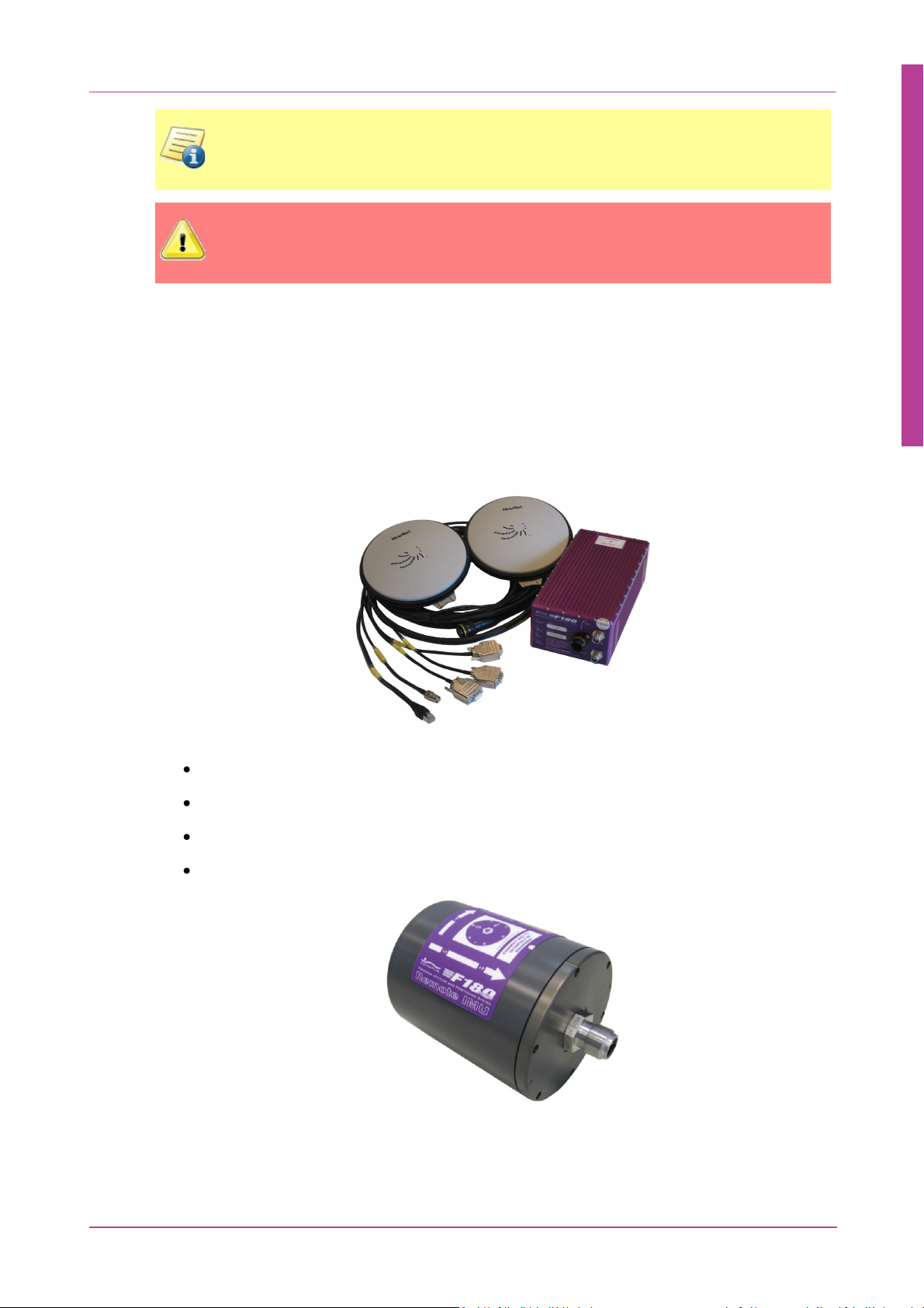
2.1
General Description
The F180R System Inertial Attitude and Positioning System comprises four separate subsystems:
Figure 1: F180R System Unit, Antennas and Interfacing Cables
the Inertial Measurement Unit with the interconnection cables
two GNSS antennas and their signal cables
software supplied on a Disc with the system
IMU components mounted in a separate water-proof housing
Figure 2: F180R System IMU component (wetpod)
Copyright © 2015 Coda Octopus Products Ltd
F180R MOTION Sensor User and Reference Guide
Page 13

2.1.1 Inertial Measurement Unit
The F180R System Box unit includes:
dual GPS receiver cards that accept and process data from each GNSS antenna
the interface electronics that process signals from the IMU and communicate the
blended position, attitude and heading measurements to the receiving PC
four LEDs to indicate the system status
The F180R System IMU unit includes:
an array of accelerometers and rate sensors to measure accelerations and rotations that
affect the unit.
The standard system operates from a DC supply in the range 9 to 18V (nominally 12V DC). This
is normally supplied through a 110 – 240V mains powered supply.
2.1.2 GNSS System
Two GNSS systems supply the information required by the F180R System to produce a heading
solution. The antennas and the dual GNSS receiver cards are all designed for use in harsh
marine environments where vibration and extremes of temperature are the norm. Low–loss
antenna cables connect the antennas to their ports on the integrated electronics unit and
ensure optimal reliability of operation.
Introduction
13
Novatel OEMV cards are the standard receivers integrated in the F180R System. Included are
also a matching pair of GNSS antennas. (Novatel GPS 701 for L1 enabled receivers and Novatel
GPS 702 for receivers enabled in L1/L2 mode.
The system comes with a standard set of 15m (Novatel CO16) antenna cables with options for
5m (Novatel C006) and 30m (Novatel C031). Refer to Antenna Cable Appendix for further
technical information on antenna cables.
2.1.3 Software
The MOTION Control software supplied with the system runs on an IBM–compatible PC under
a Microsoft® Windows™ Vista, 7 and 8 both 32 bit and 64 bit environments and provides
several important and useful functions:
configuration and real–time data display
system calibration and QC diagnostics
long period heave processing (iHeave)
interface capabilities with external receiving equipment
data acquisition and playback
Copyright © 2015 Coda Octopus Products Ltd
F180R MOTION Sensor User and Reference Guide
Page 14

Introduction
NOTE: To ship the units between installation sites or to return them to CodaOctopus
for repair, package them with care. You should retain the original transit packing cases
for this purpose. The use of improper packing for shipping any part of this equipment
will invalidate the warranty.
NOTE: In no event will CodaOctopus be liable for any indirect, incidental, special or
consequential damages whether through tort, contract or otherwise. This warranty is
expressly in lieu of all other warranties, expressed or implied, including without
limitation the implied warranties of merchantability or fitness for a particular
purpose. The foregoing states the entire liability of CodaOctopus with respect to the
products described herein.
14
2.2
Warranty
Coda Octopus Products Ltd warrants the F180R System Inertial Attitude and Positioning System
to be free of defects in materials or workmanship for one year. The warranty period begins on
the date when the equipment was shipped from CodaOctopus or from their authorised
distributor.
For information concerning the proper return location and procedure, contact CodaOctopus or
their authorised distributor. The How To Get Support sections list contact details for
CodaOctopus. The responsibility of CodaOctopus in respect of this warranty is limited solely to
product replacement or product repair at an authorised location only. Determination of
replacement or repair will be made by CodaOctopus personnel or by personnel expressly
authorised by CodaOctopus for this purpose. This warranty will not extend to damage or
failure resulting from misuse, neglect, accident, alteration, abuse, improper installation, nonapproved cables or accessories, or operation in an environment other than that intended. A
'Shockwatch' label attached to the IMU casing will show a red central vial if the unit is
subjected to severe shock. If this occurs, contact CodaOctopus technical support for test
instructions.
2.3
The solid–state inertial measurement components are not field repairable.
Calibration
We recommend to factory calibrate the F180R System hardware every 2 years to ensure
maximum accuracy. The calibration can't be performed in the field so please get in touch with
the CodaOctopus Support team to arrange a hardware calibration.
Copyright © 2015 Coda Octopus Products Ltd
F180R MOTION Sensor User and Reference Guide
Page 15

Chapter
3
Hardware
Page 16

3 Hardware
Port type
Description
Available Data protocols
Ethernet
(100 Base T)
For control, configuration,
acquisition and QC of the
F180R System system using
the supplied Windows–based
application software
MCOM binary data output string
COM1 / COM2
(RS232)
Configurable ports
outputting data at rates up to
115200 baud
Attitude data using the TSS1,
EM1000, EM3000 and TSS
HHRPdata strings
NMEA data strings for reporting
of position, fix, heading,
velocity, date, time and error
statistic using NMEA GGA, GGK,
GSA, GSV, GST, HDT, PASHR,
PPS, PRDID, PTCF, RMC, ROT,
UTC, VTG and ZDA strings
MCOM binary data output string
COM3
(RS232)
Differential correction input
at rates up to 115200 baud
RTCM
RTCA
CMR
PPS
(BNC Plug)
The system also supplies a 1
pulse per second (PPS)
output synchronised with
GPS time
Hardware
16
3.1
Communication
So far you have installed and interconnected the components of the F180R System Inertial
Attitude and Positioning System so that they are ready for use. This chapter of the manual
describes the various interface options and data output formats that you may use with the
F180R System.
The F180R System system communicates with the controlling PC and with external equipment
over various protocols using five interface ports: Ethernet, COM1, COM2, COM3 and PPS:
3.1.1 Ethernet
The Ethernet connection allows you to make maximum use of the F180R System system. The
system outputs data using a UDP (User Datagram Protocol) broadcast on port 3000 that allows
all PCs connected to the network to receive the transmitted MCOM data. It provides
significantly greater data transfer capacity than a serial RS232 connection. To receive data from
the F180R System system on a PC, the PC must have an Ethernet card fitted and be connected
Copyright © 2015 Coda Octopus Products Ltd
F180R MOTION Sensor User and Reference Guide
Page 17
Hardware
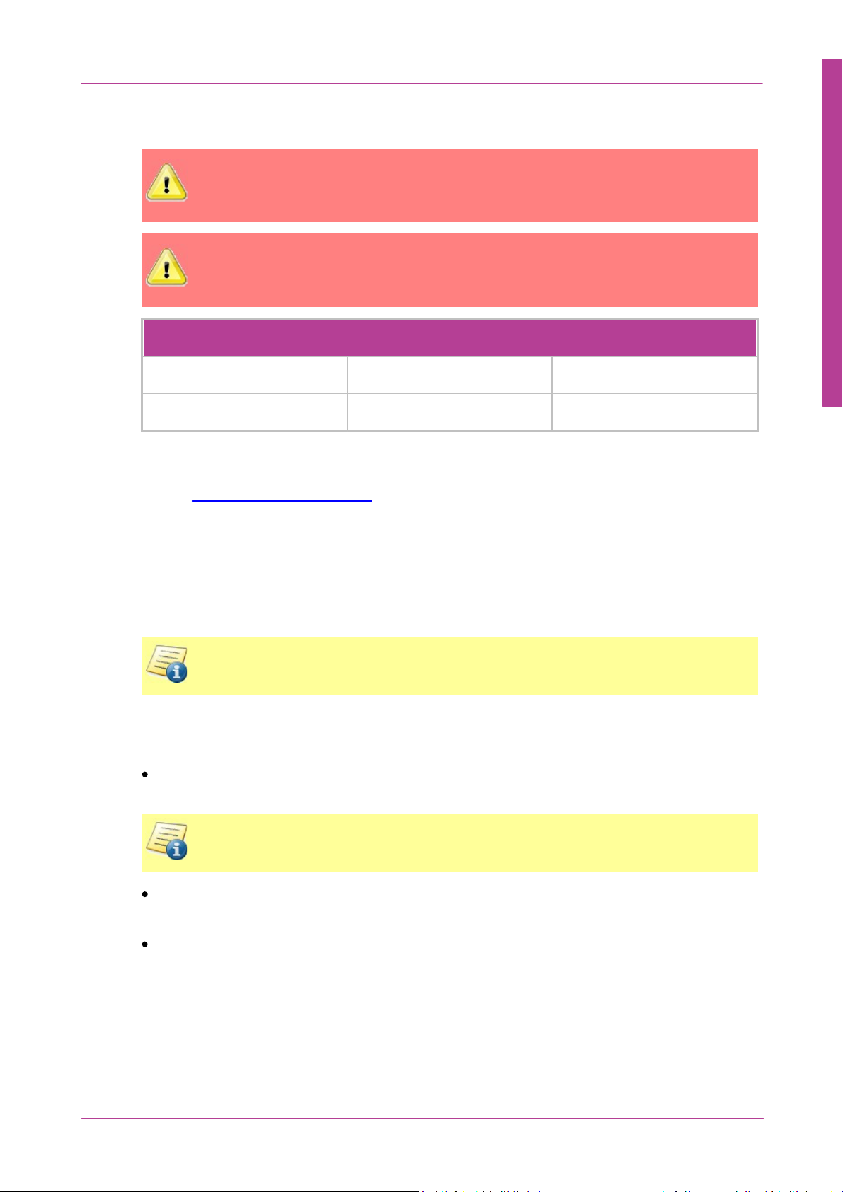
WARNING: For optimal performance you should use a direct exclusive connection
between your PC and the F180R System, thus avoiding potential data latencies and
interference that would otherwise be caused by other traffic existing on the network.
WARNING: Any firewalls between the F180R System and the control computer must
be either disabled or allow all traffic to and from the MOTION Control software to
pass.
F180R System Default Network Settings
IP Address
195.0.0.180
User configurable
Subnet Mask
255.255.255.0
User configurable
NOTE: The F180R System kit contains an in-line coupler and a CAT5 Ethernet crossover
cable which can be used for direct F180R System-to-PC connection.
NOTE: Definitions of Heading, Pitch and Roll that are output by the F180R System can
be found in Rotation Convention.
to the same 100 Base T local area network (LAN) over which the system is broadcasting. The PC
must be running the supplied MOTION Control software.
You do not need to know details of the output packet format for the UDP broadcast to work
effectively. However, if you require a detailed description of the MCOM format, please
contact support@codaoctopus.com.
17
There is an RJ–45 connector, J6, on the user interface cable that allows direct connection
between the F180R System system and a network hub/switch. You may extend the cable if
necessary by using commercially available network cables connected to the system through an
RJ–45 direct in–line coupler that has a straight–through configuration. You may also connect
the F180R System system directly to an Ethernet card in a PC. To do this the Ethernet link must
be a crossover connection.
3.1.2 Serial Outputs
The F180R System sends attitude (heave, pitch and roll) information using the TSS1 data
string format through a serial RS232 link updated at 100 Hz.
The F180R System sends attitude, heave and heading information using the binary Simrad
EM3000 format through a serial RS232 link updated at up to 100 Hz.
The F180R System outputs NMEA 0183 ASCII text sentences for position (GGA), true heading
(HDT), velocity (VTG) and Date/Time (ZDA) information through a serial RS232 link updated
at up to 50 Hz.
Copyright © 2015 Coda Octopus Products Ltd
F180R MOTION Sensor User and Reference Guide
Page 18
Once you have defined the serial output settings, after power–on and initialisation, receiving
NOTE: If you have specified a Remote Lever Arm then the position, velocity, heading
and attitude data are for the remote lever arm location.
NOTE: If you have entered a IMU Alignment/Orientation but you have not set a
Remote Lever Arm, the position, velocity, attitude data are relative the IMU and the
heading data are for the vessel.
NOTE: If you have not set either a Remote Lever Arm or a IMU Alignment/Orientation,
then the position, velocity, attitude and heading data are for the IMU.
equipment connected to the serial ports will continue to receive the TSS1 or EM3000 data
packets and/or NMEA sentences even with the Ethernet port disconnected. The heave data is
processed onboard the F180R System for a 16 second period.
3.1.2.1 MCOM
Binary data output string that include position, attitude, heading, velocity, track and speed,
acceleration, status and performance and raw data.
Hardware
18
The MCOM format is a proprietary format defined by CodaOctopus. The format description is
available to third parties who wish to implement libraries for decoding the MCOM data
stream. Contact CodaOctopus Support for further information.
3.1.2.2 NMEA
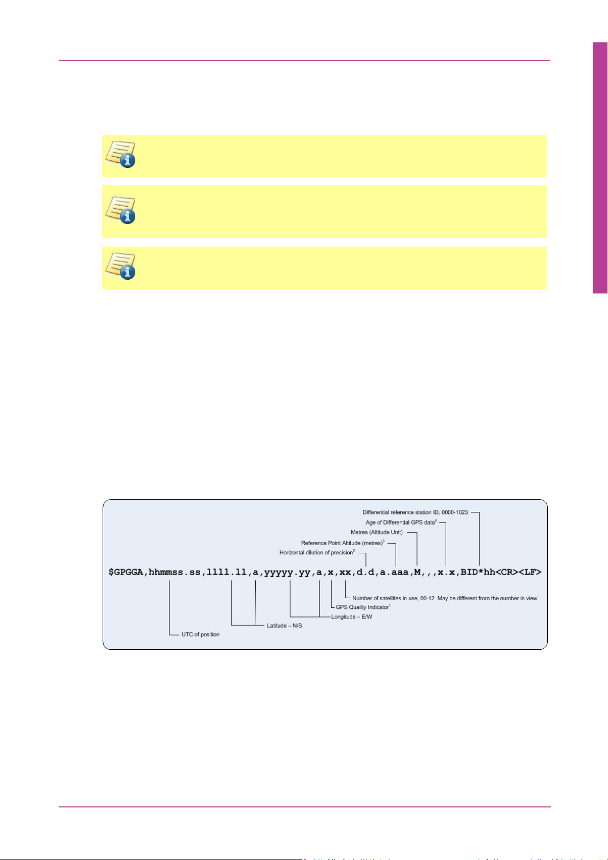
3.1.2.2.1 GGA
The NMEA - GGA string contains time, position and fix related data for a GPS receiver.
Figure 3: NMEA - GGA Format
Copyright © 2015 Coda Octopus Products Ltd
F180R MOTION Sensor User and Reference Guide
Page 19

Hardware
1. GPS Quality Indicator:
0 = Fix not available or invalid
1 = GPS SPS Mode, fix valid
2 = Differential GPS, SPS Mode, fix valid
3 = GPS PPS Mode, fix valid
4 = Real Time Kinematic. System used in RTK
mode with fixed integers
5 = Float RTK. Satellite system used in RTK
mode with floating integers
6 = Estimated (dead reckoning) mode
7 = Manual Input mode
8 = Simulator mode
The GPS Quality indicator shall not be a null
field.
2. Horizontal dilution of precision:
The system adds leading digits as required.
3. Reference Point Altitude:
Which will be the IMU sensing centre or a
remote position depending on how the system
has been configured. The Altitude output will
be to the datum that you have chosen in the
Settings Wizard.
4. Age of Differential GPS data:
Time in seconds since last SC104 Type 1 or 9
update, null field when DGPS is not used. The
system also adds leading digits as required
19
Also, note that commas separate all items, including null fields.
If no differential corrections are being received, the Age of Differential GPS data and Digital
reference station ID fields are also null.
3.1.2.2.2 GGK
The GGK string is a Trimble proprietary data string that provided time, position, position type,
and DOP. It is considered a "pseudo-NMEA" string, because it looks similar to a standard NMEA
string, but does not quite adhere to the NMEA specification.
Copyright © 2015 Coda Octopus Products Ltd
F180R MOTION Sensor User and Reference Guide
Page 20
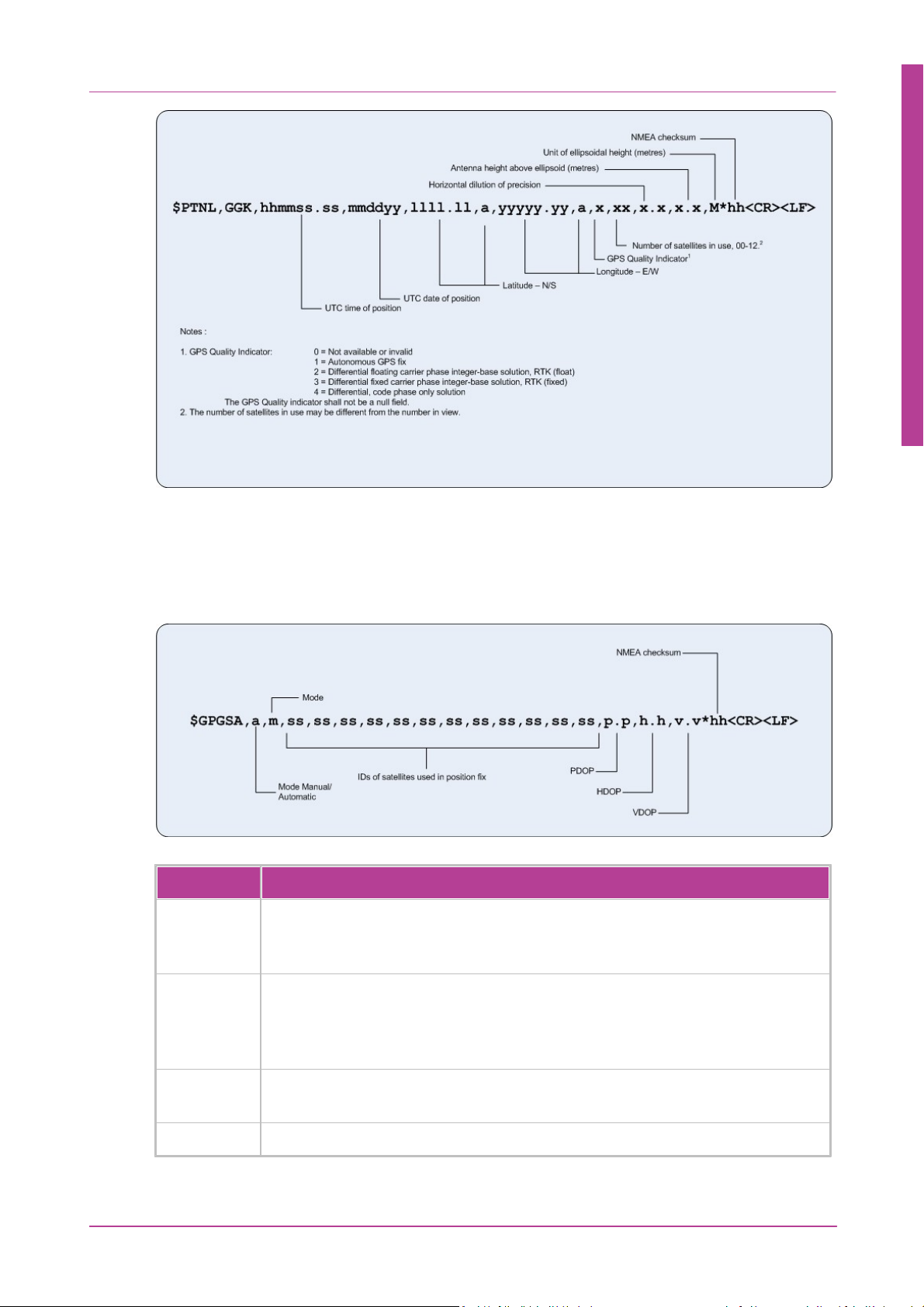
Figure 4: NMEA - GGK Format
Field
Description
a
Mode
M = Manual, forced to operate in 2D or 3D mode
A = Automatic, allowed to automatically change between 2D or 3D
m
Mode
1 = Fix not available
2 = 2D
3 = 3D
ss
IDs of the satellites used in the solution. This field is repeated 12 times. (null
for unused fields)
p.p
PDOP
Hardware
20
3.1.2.2.3 GSA
The NMEA - GSA string identifies the GPS position fix mode, the ID of the Satelite Vehicles
used for navigation, and the Dilution of Precision (DOP) values.
Figure 5: NMEA GSA String
Copyright © 2015 Coda Octopus Products Ltd
F180R MOTION Sensor User and Reference Guide
Page 21
Field
Description
h.h
HDOP
v.v
VDOP
*hh
Checksum
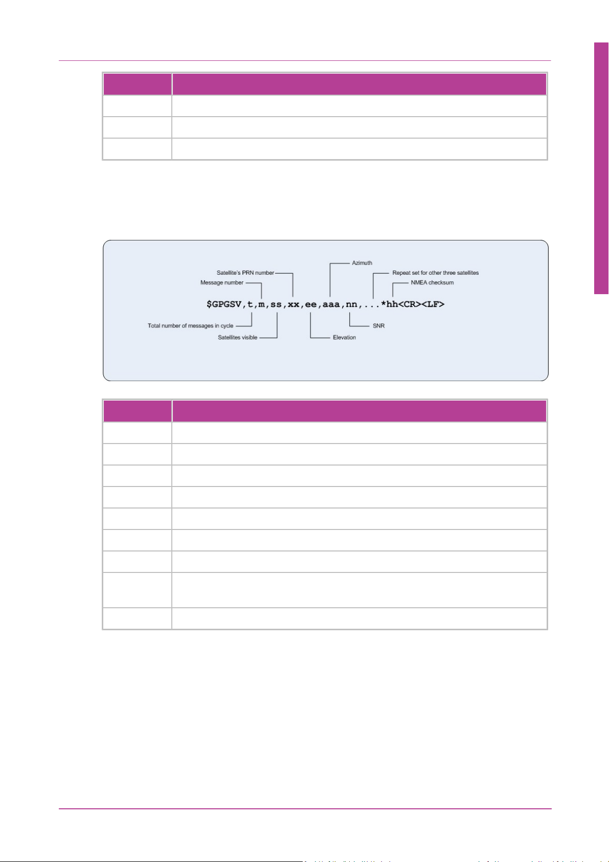
3.1.2.2.4 GSV
Field
Description
t
Total number of messages of this type in this cycle
m
Message number, 1 to 4
ss
Number of theoretically visible satellites according to the current alemanac
xx
Satellite's PRN number
ee
Elevation in degrees, 90° maximum, empty when not tracking
aaa
Azimuth, degree from true north, 000° to 359°
nn
SNR in dB, 00 to 99 dB of L1 signal, null field when not tracking
...
Repeat set of PRN, elevation, azimuth and SNR for the remaining three
satellites
*hh
Checksum
The GSV message identifies the number of satellites in view, the pseudorange noise (PRN)
numbers, elevation, azimuth, and signal-to-noise (SNR) value.
Hardware
21
3.1.2.2.5 GST
Figure 6: NMEA GSV string
This string, GNSS Psuedorange Error Statistics, is used to support Receiver Autonomous
Integrity Monitoring (RAIM). Psuedorange measurement error statistics can be translated in
the position domain in order to give statistical measures of the quality of the position
solution.
Copyright © 2015 Coda Octopus Products Ltd
F180R MOTION Sensor User and Reference Guide
Page 22
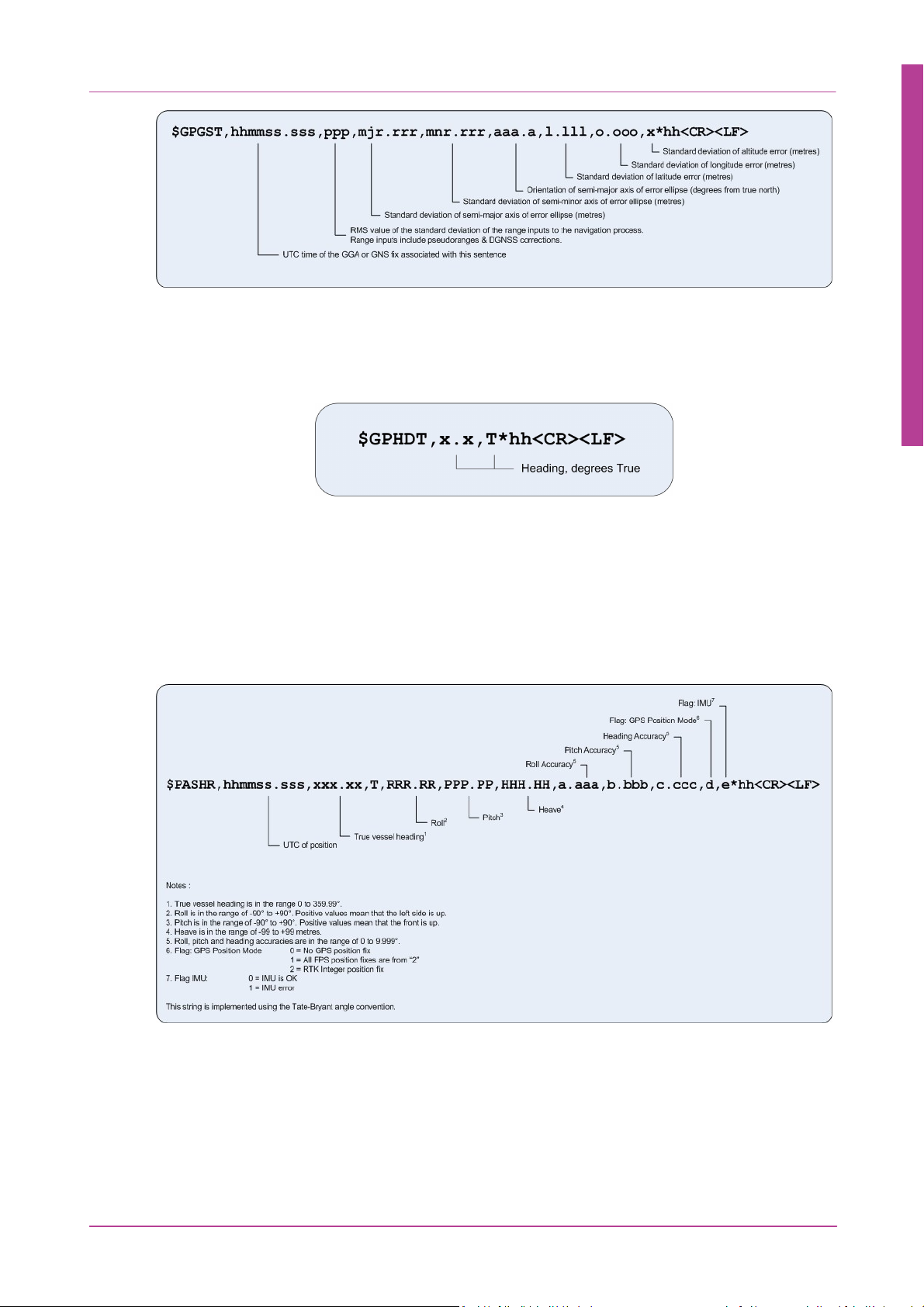
3.1.2.2.6 HDT
The NMEA - HDT string contains true heading in degrees.
Figure 7: NMEA - GST Format
Figure 8: NMEA - HDT Format
Hardware
22
Note that, in the case of the true heading field, the system adds leading digits as required.
Also, note that commas separate all items, including null fields.
3.1.2.2.7 PASHR
The PASHR sentence contains UTC time, heading, pitch, roll and heave measurements.
Accuracy data for the measurements is also included.
3.1.2.2.8 PPS
The PPS (Pulse Per Second) is a non-standard NMEA message which is useful for integrating
the F180R System with other devices. This message contains useful information such as the
PPS count, the UTC time of the current PPS, and other time-related information.
Copyright © 2015 Coda Octopus Products Ltd
Figure 9: PASHR String
F180R MOTION Sensor User and Reference Guide
Page 23
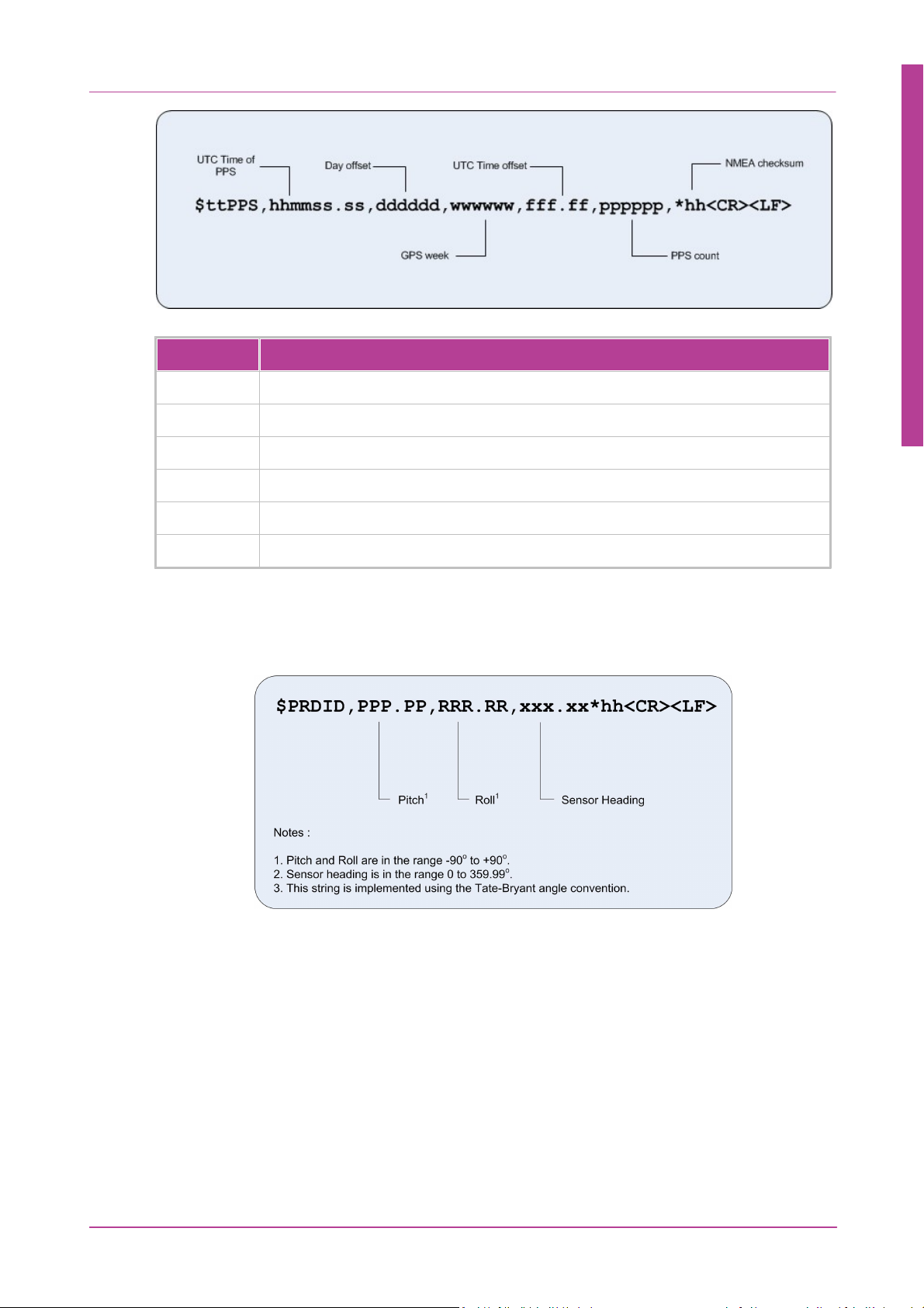
Figure 10: NMEA PPS string
Field
Description
hhmmss.ss
UTC time of PPS in hours / minutes / seconds.decimal seconds
dddddd
Day offset in days in days
wwwwww
GPS week in weeks
fff.ff
UTC time offset in seconds
pppppp
PPS count
*hh
Checksum separator and checksum
Hardware
23
3.1.2.2.9 PRDID
The PRDID sentence contains attitude data.
3.1.2.2.10 PTCF
The PTCF sentence contains the orientation (heading, pitch and roll Euler angles) of the
vessel. The angular rates for roll and pitch are also included. This sentence only contains the
orientation measurements accurate to 1 decimal place so it is not suitable for high accuracy
applications.
Figure 11: PRDID String
Copyright © 2015 Coda Octopus Products Ltd
F180R MOTION Sensor User and Reference Guide
Page 24
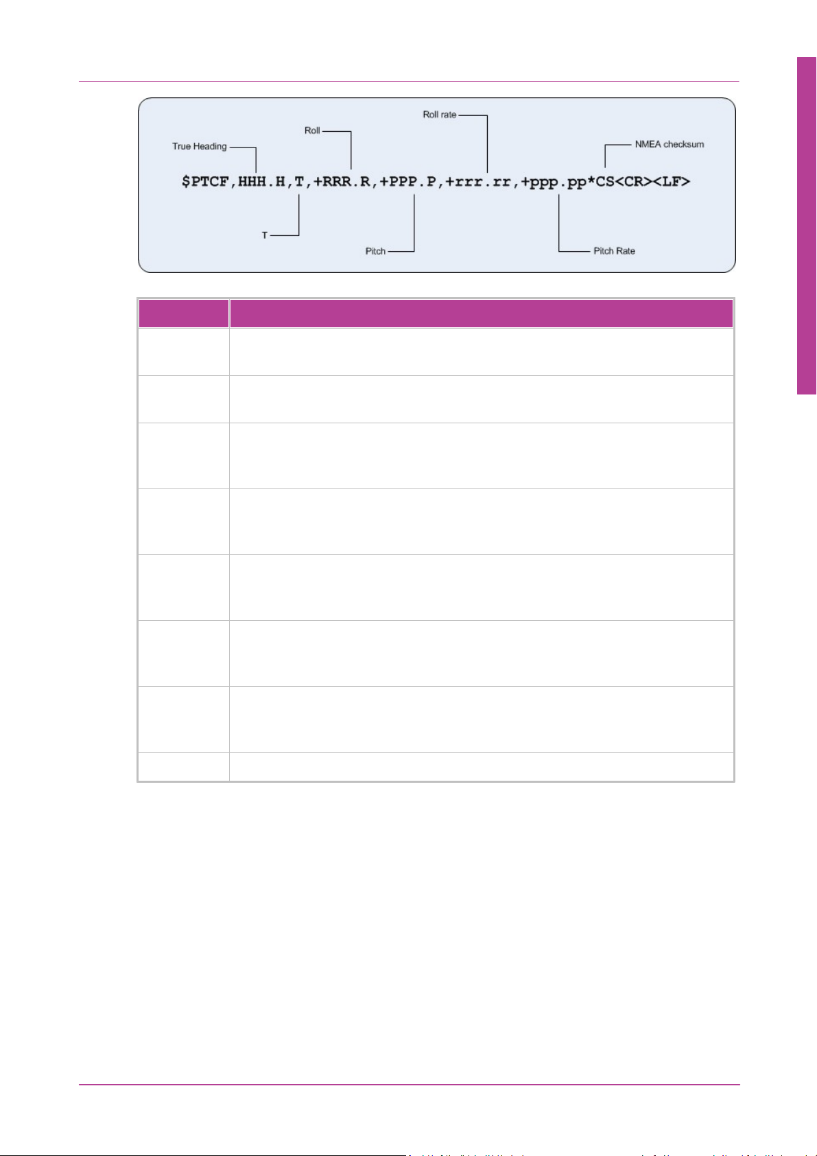
Figure 12: NMEA PTCF string
Field
Description
HHH.H
True Heading of the navigation system, from 0 to 359.99 degrees, using 1
decimal place.
T
The character ‘T’ is output by the navigation system to represent that the
heading is to true north. Grid north and magnetic north are not output.
+RRR.R
Roll of the navigation system, measured in degrees, with leading sign, leading
0’s where needed and 1 decimal place. Positive values mean that the left side
is up.
+RRR.R
Roll of the navigation system, measured in degrees, with leading sign, leading
0’s where needed and 1 decimal place. Positive values mean that the left side
is up.
+PPP.P
Pitch of the navigation system, measured in degrees, with leading sign, leading
0’s where needed and 1 decimal place. Positive values mean that the front is
up.
+rrr.rr
X-axis angular rate (roll rate) of the navigation system, measured in degrees/
second, with leading sign, leading 0’s where needed and 2 decimal places.
Positive values mean that the left side is moving up.
+ppp.pp
Lateral angular rate (pitch rate) of the navigation system, measured in degrees/
second, with leading sign, leading 0’s where needed and 2 decimal places.
Positive values mean that the front is moving up.
*CS
Checksum separator and checksum
Hardware
24
Copyright © 2015 Coda Octopus Products Ltd
F180R MOTION Sensor User and Reference Guide
Page 25

3.1.2.2.11 RMC
Field
Description
hhmmss.ss
UTC time of the position fix in hhmmss.ss format
A
Status
A = Data valid
V = Navigation receiver warning (V is output whenever the receiver indicates
that something is wrong)
llll.ll
Latitude (WGS-84)
L
Latitude direction
N = North
S = South
yyyyy.yy
Longitude (WGS-84)
Y
Longitude direction
W = West
E = East
s.s
Speed Over Ground (SOG) in knots
c.c
Course Over Ground in degree
ddmmyy
Date in ddmmyy format
m.m
Magnetic Variation in degrees
a
Direction of magnetic variation
E = Easterly variation from True course (subtracts from True course)
W = Westerly variation from True course (adds to True course)
i
Mode indicator
A = Autonomous
D = Differential
N - Data not valid
*hh
Checksum
The RMC message identifies the UTC time, status, latitude, longitude, speed over ground
(SOG), date, and magnitude variation of the position fix.
Figure 13: NMEA RMC string
Hardware
25
Copyright © 2015 Coda Octopus Products Ltd
F180R MOTION Sensor User and Reference Guide
Page 26
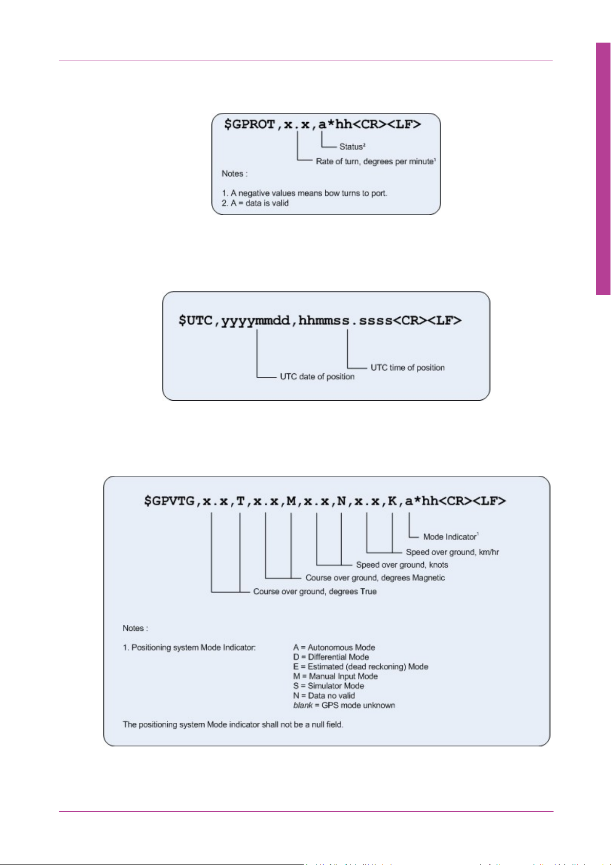
3.1.2.2.12 ROT
The ROT sentence contains Rate of Turn data.
3.1.2.2.13 UTC
The UTC sentence contains UTC date and time.
Figure 14: ROT String
Hardware
26
3.1.2.2.14 VTG
The NMEA - VTG string contains the actual course and speed relative to the ground.
Figure 15: UTC String
Copyright © 2015 Coda Octopus Products Ltd
Figure 16: NMEA - VTG Format
F180R MOTION Sensor User and Reference Guide
Page 27
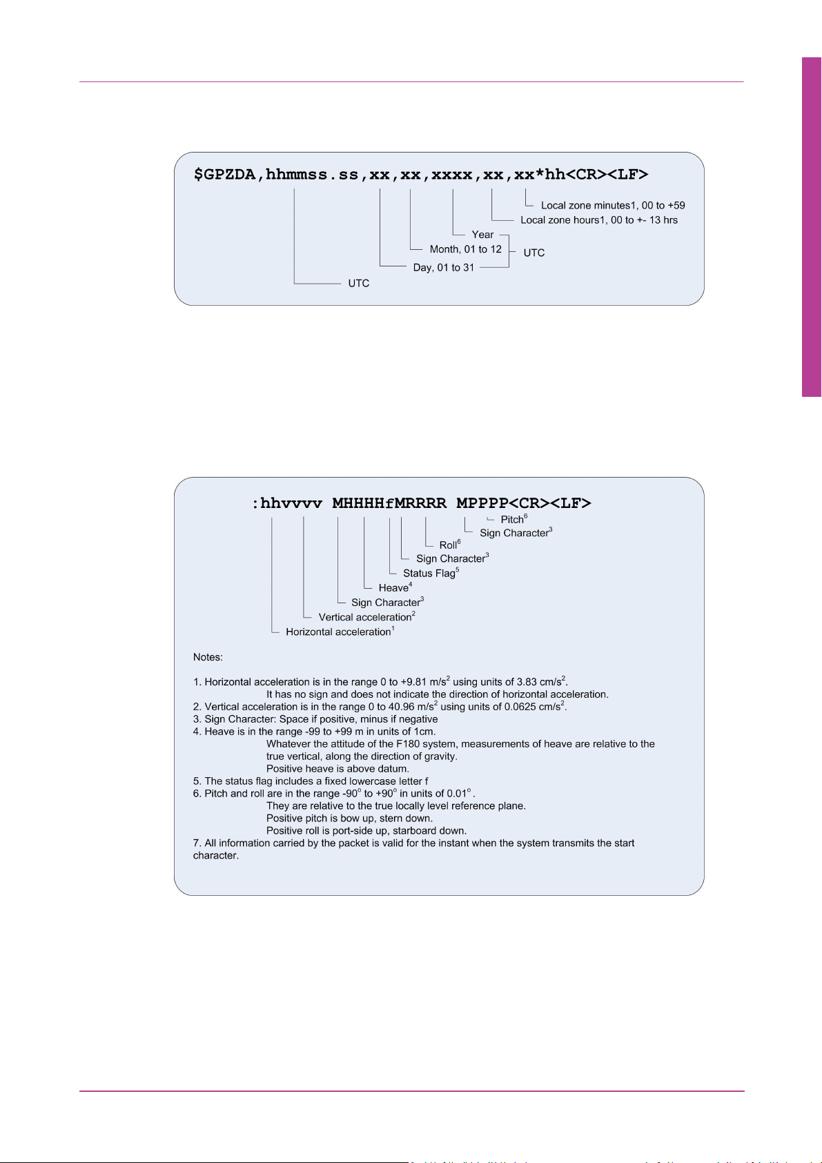
3.1.2.2.15 ZDA
The NMEA - ZDA string contains UTC time, day, month, year and local time zone information.
3.1.2.3 TSS1
The TSS1 data string format has five fields and contains 27 ASCII characters. Each string begins
with a start character and ends with the carriage return and line–feed characters. All fields
contain measurements in real–world units - the F180R System supplies acceleration
measurements using ASCII–coded hexadecimal values and heave, pitch and roll as ASCII–
coded decimal values.
Figure 17: NMEA - ZDA Format
Hardware
27
Example:
:053C22 0000f-0046 -0563
:043C86 0000f-0048 -0563
:053D1C 0000f-0050 -0563
:073D89 0000f-0052 -0562
:043CF7 0000f-0055 -0562
Copyright © 2015 Coda Octopus Products Ltd
Figure 18: TSS1 Data String
F180R MOTION Sensor User and Reference Guide
Page 28

3.1.2.4 TSS HHRP
The HHRP sentence contains attitude data.
Hardware
28
3.1.2.5 EM1000 (Tate-Bryant)
This 10–byte binary format is for use with the Simrad EM1000 multibeam sounder system.
Figure 19: HHRP String
Copyright © 2015 Coda Octopus Products Ltd
Figure20: EM1000 Format
F180R MOTION Sensor User and Reference Guide
Page 29
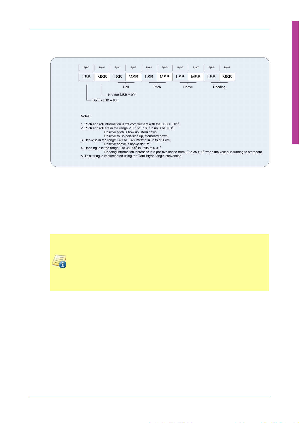
3.1.2.6 EM3000 (Tate-Bryant)
NOTE: The F180R System can only process correction strings if they are referenced to a
single base station or differential beacon. Some differential GPS receiver units can
receive and output data from multiple differential beacons simultaneously. This type
of output is not compatible with the F180R System and a single reference source
should be used in the correction input to theF180R System. This input must arrive on
the J3 user interface cable.
Receive (Rx) pin on J3 is Pin 3 for correction input
This 10–byte binary format is for use with the Simrad EM3000 multibeam sounder system.
Figure 21: EM3000 Format
Hardware
29
3.1.3 RTK and Differential Corrections
The F180R System can decode corrections supplied in RTCM, RTCA and CMR and CMR from
external GPS receivers or standalone demodulators. The system is configured by default to
receive RTK and differential correction information, using the RTCM format with default input
port settings 9600,8,N,1,OFF. You can change the correction configuration in the Configuration
Wizard
Copyright © 2015 Coda Octopus Products Ltd
F180R MOTION Sensor User and Reference Guide
Page 30
Hardware
Format
Description
RTCM
The F180R System will accept standard RTCM-SC104
messages:
Version 1/2.2: 3,9,15,16,16t,18,19,20,21,22,59
Version 3: 1001, 1002, 1003, 1004, 1005, 1006
(Please note that only later releases of OEM4 based system
are capable of utilising the RTCM Version 3 messages. Please
contact CodaOctopus for exact information on your F180R
System model.)
RTCA
The F180R System will accept RTCA Standard Type 7
messages.
CMR/CMR+
Trimble open format and available as an output from their
instruments and some other 3rd party.
NOTE: The formats listed above are sent in binary format. Thus you may not see any
recognisable data if the data output is viewed on Hyperterminal. This is worth noting
when trying to troubleshoot F180R System input issues.
30
For further information on correction formats contact CodaOctopus.
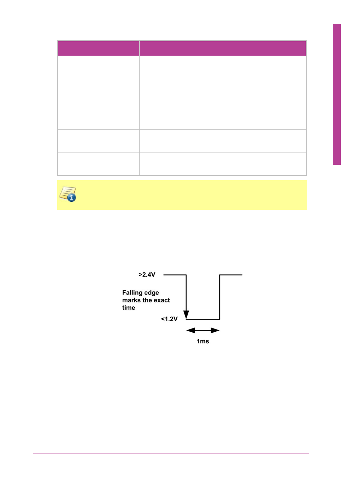
3.1.4 PPS
The PPS timing output pulse is a TTL–level high–to–low (>2.4V to <1.2V) transition coincident
(to within 1µs) with the PPS strobe of GPS time. The pulse width is 1ms.
In order to minimise the chance of encountering problems related to time synchronisation we
recommend that a PPS converter is interfaced to one of the onboard serial ports on the
navigation computer and not to external or USB serial ports.
Figure 22: PPS timing output pulse
3.2
Copyright © 2015 Coda Octopus Products Ltd
Technical Specification
CodaOctopus operates a policy of continual product improvement. The technical specification
listed below for the systems manufactured at the time of writing and is therefore subject to
change without notice. For details of current specifications, refer to the CodaOctopus website
F180R MOTION Sensor User and Reference Guide
Page 31

at www.codaoctopus.com or contact CodaOctopus for additional information.
Product
RT20 RTK
L1/L2 on
1st
Antenna
RT2 RTK
Satellite
GPS
L1/L2 on
2nd
Antenna
Description
F180R
Standard F180R with up
to 20 cm positional
accuracy when used with
a suitable external RTK
receiver and base-station
F185R
As standard F180R but
with improved positional
accuracy capability up to
1cm when used with
suitable external RTK
receiver and base-station
F185R+
As F185R but with L1/L2
enabled on both
receivers for rapid
heading initialisation.
F190R
As F180R but with
integrated satellitebroadcast differential
correction receiver
providing up to 20 cm
positional accuracy.
Additional subscription is
required.
F190R+
As F190R but with L1/L2
enabled on both
receivers for rapid
heading initialisation.
3.2.1 Model Specifications
Hardware
31
Copyright © 2015 Coda Octopus Products Ltd
F180R MOTION Sensor User and Reference Guide
Page 32

3.2.2 Interfaces
Ethernet 100 Base-T
Function
Control, set–up and QC monitoring of the
system using MOTION Control Windows
application software.
MCOM Format
Outputs include position, attitude, heading,
velocity, track and speed, acceleration, status
and performance and raw data.
Serial 1 and 2 Outputs
High data rate output packet (100 Hz) for
high–speed interfacing
Attitude data
TSS1, EM3000, EM1000, HHRP, PASHR and
PRDID attitude strings. RS232 (DB9) up to 115k
baud
NMEA data
GGA position, HDT heading, VTG velocity, ZDA
date/time, GST GNSS Error, etc. RS232 (DB9)
up to 115k baud
MCOM Format
Outputs include position, attitude, heading,
velocity, track and speed, acceleration, status
and performance and raw data
Serial 3 Input
RTK/Differential Correction Input
RS232 (DB9) up to 115k baud.
Receive (Rx) pin on J3 is Pin 3 for correction
input
Other
1 PPS
Hardware
32
Serial outputs 1 and 2 can be configured for any data output type, including the binary MCOM
format.
Copyright © 2015 Coda Octopus Products Ltd
F180R MOTION Sensor User and Reference Guide
Page 33

3.2.3 Reference Frames
Global Reference System
Horizontal Domain
WGS84 Latitude, Longitude
Vertical Domain
WGS84 Ellipsoidal Height
OSU89B Geoid Height
User Defined
Time Domain
Coordinated Universal Time (UTC)
Local Reference System - F180R System Standard Orientation
Figure 23: Local Reference System
NOTE: The IMU frame for the F180R System wetpod are defined with positive y-axis
through connector plate and positive x and z-axis according to marking on the unit
itself.
Lever Arm Convention
If you have specified a Remote Lever Arm then the position, velocity, heading, heave and
attitude data are for the remote lever arm location.
If you have not set a Remote Lever Arm, the position, velocity, heave, attitude data are
relative the IMU and the heading data are for the vessel.
Hardware
33
Copyright © 2015 Coda Octopus Products Ltd
F180R MOTION Sensor User and Reference Guide
Page 34

Hardware
NOTE: Running through the MOTION Settings Wizard before physically installing the
F180R System on the vessel could provide helpful as it would give a better
understanding of what is required during the hardware installation.
NOTE: It is a relatively easy operation to transfer theF180R System between different
vessels. This is of particular benefit for those who will use the system in a series of
short–term operations conducted using different vessels.
34
3.3
Hardware Installation
While designing the F180R System Inertial Attitude and Positioning System, CodaOctopus has
made it a high priority to ensure that the system is easy to install, configure and use. With a
need for only the bare minimum of installation parameters to be supplied manually, the
system intelligently evaluates the details of its own installation and uses them to deliver
navigation measurements of optimal accuracy.
These instructions explain how to install and connect the components of the F180R System.
Although it is easy to install and configure the system, you should take some time to read
these instructions and identify each of the components of the system before you begin so that
you can be sure you have everything you need readily available.
A typical installation should then be accomplished quickly so that you may have the system
running and delivering accurate measurements within less than a couple of hours. Unlike
other similar systems, the F180R System requires no complex installation measurements that
delay progress and make the system susceptible to simple errors of geometry.
The task sequence you need to follow is:
1. Identify the major components of the F180R System.
2. Select and prepare suitable locations in the vessel to install them.
3. Install the cabling and components on the vessel.
4. Configure the installation.
3.3.1 Component Identification
The major components of the F180R System Inertial Attitude and Positioning System as they
are shipped are shown below.
The shipping case includes:
Copyright © 2015 Coda Octopus Products Ltd
F180R MOTION Sensor User and Reference Guide
Page 35

the F180R System Box Unit
NOTE: For L1 deployment this is the Novatel GPS-701 antenna. For L1/L2 deployment
this is the Novatel GPS-702 antenna.
WARNING: Although selected for their ruggedness, the solid–state accelerometers
and rate sensors used in the IMU are susceptible to excessive shock and vibration.
Refer to the environmental specifications for details. Treat the IMU with care when
you handle it—store it in the transit case until you are ready to install it. Never drop
the IMU or subject it to shocks. A 'Shockwatch' label attached to the IMU casing will
show a red central vial if the unit is subjected to severe shock. If this occurs, return the
unit to CodaOctopus Limited for test and repair. The solid–state inertial measurement
components are not field repairable.
WARNING: A common point of failure is damage to the two antenna cables. Any
exterior or interior damage to the cables can deteriorate the GNSS signal strength to a
point where the system turns unreliable. Special care should therefore be considered
when installing and fixing the cables to the vessel structure. Cables should not be
subject to a short bend radius or stepped on as it can break the internal insulation
layer.
Wetpot IMU
two identical GNSS antennas
Hardware
35
antenna mounting components
two identical antenna cables with appropriate connectors at both ends
the power connection cable
Copyright © 2015 Coda Octopus Products Ltd
F180R MOTION Sensor User and Reference Guide
Page 36

3.3.2 Antenna Installation
NOTE: Do not mount the antennas on flexible masts, or on mast platforms that tend to
move significantly relative to the vessel.
NOTE: Multipath reflections of GPS signals are the dominant source of errors in
theF180R System. Typical reflectors include flat surfaces on the vessel and the surface
of the sea. Locating the antennas as high as possible will reduce the multipath
reflections from the sea surface and vessel superstructure.
NOTE: You should consult the documentation for any microwave emitters or radar
antennas mounted on the vessel close to your proposed F180R System antenna
mounting location. The F180R System antennas are sensitive to any electromagnetic
radiation that might interfere with electrical equipment.
NOTE: For L1 deployment this is the Novatel GPS-701 antenna. For L1/L2 deployment
this is the Novatel GPS-702 antenna. For mixed systems the antennas are marked as
primary and secondary in order to avoid confusion.
There are several important points that you must remember when you choose a location for
the GPS antennas. You must mount them:
outside in an elevated position on the vessel where they have a clear view of the sky in
all directions
rigidly with respect to each other and with respect to the IMU
with a known separation distance between them
in locations that are least likely to experience multipath satellite signals caused by
reflections off nearby structures or flat surfaces
Hardware
36
in locations where salt deposits are unlikely to accumulate and degrade the received
signal quality
in locations isolated from high levels of vibration, shock or electrical noise
more than 5 metres from radar, UHF, satellite communications or other communications
antennas
where they are not exposed to extremes of temperature beyond the acceptable limits
listed in the environmental specifications
where the antenna cables can run easily in one continuous length from each antenna to
the F180R System Box
To install the antennas you will need:
the supplied antennas
antenna cables
Copyright © 2015 Coda Octopus Products Ltd
F180R MOTION Sensor User and Reference Guide
Page 37

NOTE: The F180R System comes with a standard set of 15m (Novatel CO16) antenna
cables with options for 5m (Novatel C006) and 30m (Novatel C031). Refer to Appendix
- Antenna Cable for further technical information on antenna cables.
the optional antenna mounting bar (supplied on request)
NOTE: It is essential that you check and record the separation distance between
the two GPS antenna centres before you finally mount the antenna assembly,
otherwise it might be difficult to obtain an accurate measurement. It is essential
that you measure this antenna separation to an accuracy of better than 5mm. This
measurement will be used as the Antenna Separation input parameter in the
MOTION Control application. Once you have done this, the system will use
measurements delivered by the dual GPS receivers to 'aid' the independent
measurements of the IMU.
For simplicity and convenience, you may make this measurement as soon as you
have mounted the two GPS antennas on their mounting bar. For accurate
measurement make sure you measure at the Antenna Reference Points.
a kit of suitable tools
waterproof sealing tape or compound
cable clips
To install the antennas:
1. Choose a location for the antennas using the guidelines printed above.
Hardware
37
Figure 24: Antenna Installation
2. Fix the optional mounting bar or your antenna support in position using bolts at both
ends to ensure rigidity of antenna installation. The bolt dimension is 5/8 inch by 2
inches, UNC stainless steel.
3. Decide which end of the mounting bar will support the primary GPS antenna and which
end will support the secondary GPS antenna.
Copyright © 2015 Coda Octopus Products Ltd
F180R MOTION Sensor User and Reference Guide
Page 38

Hardware
NOTE: For simplicity, the standard recommended configurations are either:
(a) with the antenna mounting bar level and at right–angles to the ship's
heading, and the primary antenna located on the port side of the vessel with
the secondary antenna mounted on the starboard side; or
(b) with the antenna mounting bar level and parallel to the ship's heading,
with the primary antenna located on the forward end of the mounting bar and
the secondary antenna on the aft end of the bar.
However, you may mount the antennas at other orientations if you need to. You
must set the antenna orientation chosen in Secondary Antenna Configuration of
the Configuration Wizard.
NOTE: The phase centres of the GPS antennas might move by several millimetres
as the vessel turns or as satellites move across the sky. When both antennas have
the same orientation, their phase centres will move approximately together. This
will help to maintain optimal measurement accuracy under all conditions.
4. Fit the primary GPS antenna to the mounting bar at its chosen location by passing the
central support stud through the hole and fitting the securing washer and nut.
5. Run one of the supplied cables from the F180R System Box to the primary GPS antenna
location. Use clips or adhesive tape to secure the cable at regular spacings. Do not
subject the cable to sharp bends, stresses or points where extended vibration might
cause wear to the cable.
38
6. Connect the cable to the primary GPS antenna and apply waterproof sealing tape to seal
the connection against water ingress. Do not over–tighten the connector.
7. The primary antenna cable in F180R System kit is normally marked with a red sleeve.
Alternatively attach a label to identify this as the primary antenna cable.
8. Fit the secondary GPS antenna to the mounting bar, following the same procedure that
you used for the primary antenna.
9. Before you tighten the fixings on the secondary antenna, turn it so that the connector
port faces in approximately the same direction as that on the primary GPS. This gives
both antennas the same orientation with respect to the vessel.
10.Run the secondary antenna cable from the F180R System Box to the secondary GPS
antenna location.
11.Connect the second supplied cable to the secondary GPS antenna and seal it against
water ingress, following the same precautions and instructions used for the primary
antenna cable.
12.Attach a label at the bottom end to identify this as the secondary antenna cable.
13.Connect both antenna cables to the F180R System Box through their appropriate
connection ports. Upper BNC port is primary antenna connection. Lower BNC port is
secondary antenna connection.
14.Connect the user interface cable to the 22–way port on the F180R System Box.
Copyright © 2015 Coda Octopus Products Ltd
F180R MOTION Sensor User and Reference Guide
Page 39

Hardware
Port
Identification
Description
Function
J1
Deutsch AS612–35SA 22–way
Main connector to the <%PRODUCTNAME%>
Box.
J2
DB9 9–way female D–type.
Serial RS232 attitude data to receiving
equipment. (COM1)
J3
DB9 9–way female D–type.
Serial RS232 RTK/Differential correction
from an external receiver. (COM3)
J4
DB9 9–way female D–type
Serial RS232 navigation data to receiving
equipment. (COM2)
J5
BNC socket
1 PPS timing signal
J6
8–way RJ45 100 Base-T plug
Ethernet connection port to host PC
J8a
Deutsch connector
IMU Pod connection, connection on the <%
PRODUCTNAME%> Box side
J8b
Marine connector
IMU Pod connection, connection on the IMU
pod side
PWR
Open tails
Supply, supply return and ground
15.Use the information in the table below to make connections between the user
interface cable and the power supply and external equipment including the host PC and
wetpod.
39
Copyright © 2015 Coda Octopus Products Ltd
Figure 25: F180R System Connectors Diagram
F180R MOTION Sensor User and Reference Guide
Page 40

3.3.3 IMU Installation
WARNING: The F180R System IMU contains a number of sensitive and expensive solid
state accelerometer and gyro components. You will cause permanent damage to these
components if you handle the F180R System IMU carelessly. To prevent irreversible
damage, handle the F180R System IMU with great care while you unpack and install
the F180R System IMU.
NOTE: Retain the original packing cases that contain the system during shipment and
use them if you must transport the system from one location to another or if you must
return it to CodaOctopus for any reason. You will invalidate the warranty if you use
improper or inadequate packing to store or transport any part of the system.
NOTE: Definitions of Heading, Pitch and Roll that are output by theF180R System can
be found in Appendix - Rotation Convention.
The F180R System IMUcontains a number of sensitive measuring devices. You must always
take great care when you handle this unit. In particular, be very careful when you place the
F180R System IMU on or mount it to any surface. It is not possible to repair the inertial
measurement components of the F180R System IMU in the field. If you suspect the F180R
System has developed a fault, return it to CodaOctopus for repair.
Install the F180R System at a suitable location in the vessel:
Hardware
40
Installation Orientation
The default installation orientation for the F180R System IMU relative to the vessel is with the
connector end plate (y-axis) pointing to starboard, and the z-axis marked on the unit pointing
down. Please note that the unit can be mounted in any orientation where the exact mounting
orientations are provided in the Configuration Wizard.
(See Reference Frame for coordinate conventions)
The IMU should be installed as near as is reasonably practical to the sensor whose motion it
is to monitor. This will minimise the length of any lever arms and ensure that the IMU
motion matches that of the sensor as closely as possible.
The chosen location must provide rigid support so that the IMU does not move relative to
either of the GPS antennas. You do not need to install the IMU at or near the vessel's centre
of rotation. There will be no degradation in performance if you mount the IMU away from
the vessel's centre of rotation.
Special algorithms ensure the IMU will work in any installed orientation with no loss of
performance. They also ensure the system performs well in high vibration environments.
However, you should avoid high vibration environments where possible because these
have additional noise components that will corrupt your measurements. The noise
components are due entirely to the vibration motion and do not arise within the F180R
System system.
If the mounting location for the F180R System IMU is likely to exceed the limits for vibration
and shock listed in the environmental specification, then you should provide special anti–
vibration mounting arrangements. Install the IMU away from strong heat sources. Avoid
subjecting it to rapid changes in temperature, which can degrade the system performance.
Copyright © 2015 Coda Octopus Products Ltd
F180R MOTION Sensor User and Reference Guide
Page 41

Hardware
NOTE: The F180R System Box is NOT waterproof. Do not install it where it is likely to
become wet at any time. However the IMU/wetpod is.
Choose a location for the Box and IMU that allows you to connect it to other components of
the system easily using the supplied cables.
To install the F180R System System you will need:
the F180R System housing and wetpod
all supplied power and interconnection cables
a kit of suitable tools
waterproof sealing tape or compound
cable clips
To install the F180R System Box:
1. Follow the guidelines above to select a suitable mounting location for the <%
PRODUCTNAME%> Box.
41
3.4
2. Attach the F180R System Box directly to the mounting location using a rigid method of
securing the unit in position. The only mounting components supplied by CodaOctopus
with the F180R System are the two 90° full length mounting brackets.
3. Attach cables throughout the system.
To install the F180R System wetpod:
1. Follow the guidelines above to select a suitable mounting location for the F180R System
IMU.
2. Securely attach the F180R System IMU to the sensor pole.
3. Attach cables throughout the system.
Measure Installation Parameters
The installation parameters you require for system calibration are:
Antenna Baseline (antenna separation distance)
Antenna Offsets
Antenna Orientation
Additionally, there are a number of configuration parameters which are not required for
calibration of the system; however they are required to correctly configure the output of the
system.
IMU Orientation
Remote Lever Arms
Copyright © 2015 Coda Octopus Products Ltd
F180R MOTION Sensor User and Reference Guide
Page 42

All measurements are made in accordance with the conventions stated in the Reference
Heading mounting rotation (about z Axis)
alignment of the IMU x-y axis to vessel's forestarboard axis. Clockwise rotation is positive (looking
down on the wetpod).
Figure 26: IMU Orientation
Pitch mounting rotation (about y Axis)
alignment of the IMU x-z axis to the vessel's fore-down
axis. Anti clockwise rotation, where the connector
moves to the aft, is positive.
Roll mount rotation (about x Axis)
alignment of the IMU y-z axis to the vessel's starboarddown axis. Clockwise rotation looking at the connector
is positive.
WARNING: When using an other than standard like installation see the graphics in the
wizard for axis alignment changes.
NOTE: Definitions of Heading, Pitch and Roll that are output by the F180R System can
be found in Appendix - Rotation Convention.
Frame Chapter.
3.4.1 IMU Orientation
It is rarely possible to install any system on a vessel so that it is perfectly level and oriented in
exact fore–aft alignment with respect to the vessel's frame. Any misalignment between the
system and the vessel's frame might therefore affect the accuracy of measurements delivered
by the system by applying a permanent offset to them. The standard installation orientation
of the F180R System relative to the vessel is for the connector end plate to point directly aft.
The system should also sit level relative to the mounting surface. This orientation will ensure
the system is installed parallel to the vessel's heading axis.
The F180R System allows you to input measured differences between theF180R System frame
of reference and the vessel frame of reference. If it is not possible to make these
measurements then they can be evaluated after system calibration.
The rotation angles that you require are the differences between the F180R System frame of
reference and the vessel's frame of reference. For simplicity the angles are defined as the
rotations needed to re-align the F180R System with the vessel, and use the following
conventions:
Hardware
42
For ease of use MOTION Control provides visual aid in the Settings Wizard for 90° and 180°
orientations in all directions.
Copyright © 2015 Coda Octopus Products Ltd
F180R MOTION Sensor User and Reference Guide
Page 43

Measure and write down the rotation angles required to bring the F180R System into
Correction Type
GPS Offset Measurement Accuracy
Stand alone
0.5 metre or less
DGPS
2.0 metre or less
RTK
2.0 metre or less
NOTE: You should measure the antenna offset distances in the vessel frame of
reference. MOTION Control sets the Stand Alone accuracy to a maximum of 0.5
metres. As the Differential/RTK positional accuracies are of a higher magnitude,
baseline measurements for these systems can be made to 2.0 metres.
NOTE: You should never over–estimate how accurately you have measured the offset
distances. When estimating the accuracy of your measurements you should also allow
for any misalignment of the unit with the vessel's (X, Y, Z) axes, which will also affect
the overall measurement accuracy of the F180R System. For example, if an offset is
10m and you have not allowed for a 1° heading alignment then the Y offset
measurements will include 0.17m error arising from this 1° error.
alignment as detailed above. Later, you must input these values in the MOTION Settings
Wizard.
3.4.2 Antenna Offset
It is necessary to configure the F180R System with Antenna Offset parameters that describe
the position of the primary GNSS antenna relative to the F180R System IMU. To provide this
important information you must measure the antenna offset distances.
The antenna offset distances are the differences in the fore–aft, port–starboard and vertical
installation positions of the F180R System IMU and the primary GNSS antenna. You must
measure each of the antenna offset distances from the F180R System IMU to the primary
antenna and ensure that they are measured to within the maximum specified accuracies.
Hardware
43
Copyright © 2015 Coda Octopus Products Ltd
F180R MOTION Sensor User and Reference Guide
Page 44

Hardware
Fore-Aft offset—the distance between the installed
position of the F180R System IMU and the centre of the
primary GNSS antenna along the fore–aft line of the
F180R System IMU.
Figure 27: GPS Offsets
Port-Starboard offset—the distance between the
installed position of the F180R System IMU and the
centre of the primary GNSS antenna along the port–
starboard axis of the F180R System IMU.
Above-Below offset—the distance between the
installed position of theF180R System IMU and the
primary GNSS antenna along the vertical axis of the
F180R System IMU.
WARNING: It is essential that you measure this antenna separation to an accuracy of
better than 5mm.
Please refer to the System Dimensions for the IMU reference point. Measure and write down
the offset distances as detailed above. Also make an estimation of the accuracy with which
you have made these measurements. Later you must type these values into the MOTION
Control Settings Wizard.
44
3.4.3 Antenna Separation
The antenna mounting arrangement, allows for an antenna separation distance, or baseline
length, of between 1 and 4 metres. This is a single, straight–line measurement between the
centres of both antennas and is easy to measure after you attach the antennas to the
mounting bar and before you install the mounting bar on the vessel.
Optimal system performance during the heading initialisation and calibration phases can be
achieved by using the smallest antenna baseline that delivers measurements meeting your
specification. A longer baseline will give increased heading accuracy, however the time taken
to Heading Initialise and system to calibrate will also take long. Thus optimal heading
initialisation periods and calibration times are achievable with baseline lengths of 2.0m or
less.
It is essential to measure the straight–line distance - the antenna separation - between the
antenna centres as accurately as possible.
This measurement will be used as the Antenna Separation input parameter in MOTION
Control. Once you have done this, the system will use measurements delivered by the GNSS
receivers to 'aid' the independent measurements of the IMU.
If you have not already done so, measure and record the antenna separation distance to an
accuracy of better than 5mm. Later you must input this measurement in the MOTION Control
Settings Wizard.
Copyright © 2015 Coda Octopus Products Ltd
F180R MOTION Sensor User and Reference Guide
Page 45

3.4.4 Antenna Orientation
With the antenna mounting bar aligned port–starboard
with the primary antenna to port, the orientation
rotation is nominally +90°.
Figure 28: GPS Orientation
With the antennas mounted fore–aft (in line with the
vessel) and the secondary antenna aft of the primary
antenna, the orientation rotation is nominally 180°.
With the antennas mounted fore–aft (in line with the
vessel) and the secondary antenna forward of the
primary antenna, the orientation rotation is nominally
0°.
A height offset positive means that the Secondary
Antenna is above or below the Primary Antenna.
NOTE: These nominal GPS orientation rotation and elevation angles must be set
accurately to ensure optimal performance. Following the series of calibration
manoeuvres the system will refine the measurements to more accurate values, and
these are saved with the calibration.
The Antenna Orientation has two components — rotation and elevation — that tell the F180R
System what angle the GNSS antenna mounting bar is at relative to the vessel's heading axis,
and what elevation angle the GNSS antenna mounting bar makes relative to the vessel's base
plane.
Rotation is expressed as the angular difference between the vessel's heading and the antenna
mounting bar, using the primary antenna as pivotal point.
Elevation is expressed as height offset of the secondary antenna to the primary antenna, that
is, the difference in altitude between the Secondary and the Primary Antennas.
Hardware
45
Measure and write down the Antenna orientation rotation and height offset as detailed
above. Later you must type these values into the appropriate fields of the MOTION Control
Settings Wizard.
3.4.5 Remote Lever Arms
The F180R System allows you to set a 'Remote Lever Arm' distances X, Y and Z of the F180R
System so that you may specify the point at which you want the motion outputs to be
computed for. The Remote Lever Arms are configured in Settings Wizard.
With the default zero settings for the X, Y and Z remote lever arm distances, the system
outputs all data referenced to its internal measurement point which is marked on the IMU
enclosure. If you want the system outputs referenced to some other point, for example at a
sonar head, you must enter the lever arm distances between the F180R System IMU and the
desired measurement point.
Copyright © 2015 Coda Octopus Products Ltd
F180R MOTION Sensor User and Reference Guide
Page 46

Hardware
NOTE: If you have specified a Remote Lever Arm then the position, velocity, heading
and attitude data are for the remote lever arm location.
NOTE: If you have entered a Vessel Orientation but you have not set a Remote Lever
Arm, the position, velocity, attitude data are relative the IMU and the heading data are
for the vessel.
NOTE: If you have not set either a Remote Lever Arm or a Vessel Orientation, then the
position, velocity, attitude and heading data are for the IMU.
The remote lever arm must be given in the vessel reference frame.
You should try to keep the remote lever arms as short as possible, because vibrations will
introduce motion errors proportional to the lever arm distance. Whenever possible mount the
IMU near the required measurement point.
For heave measurements is set to AC coupling, which will generate a heave output that has a
long term average of zero.
46
3.5
Communication
So far you have installed and interconnected the components of the F180R System Inertial
Attitude and Positioning System so that they are ready for use. This chapter of the manual
describes the various interface options and data output formats that you may use with the
F180R System.
The F180R System system communicates with the controlling PC and with external equipment
over various protocols using five interface ports: Ethernet, COM1, COM2, COM3 and PPS:
Copyright © 2015 Coda Octopus Products Ltd
F180R MOTION Sensor User and Reference Guide
Page 47

Hardware
Port type
Description
Available Data protocols
Ethernet
(100 Base T)
For control, configuration,
acquisition and QC of the
F180R System system using
the supplied Windows–based
application software
MCOM binary data output string
COM1 / COM2
(RS232)
Configurable ports
outputting data at rates up to
115200 baud
Attitude data using the TSS1,
EM1000, EM3000 and TSS
HHRPdata strings
NMEA data strings for reporting
of position, fix, heading,
velocity, date, time and error
statistic using NMEA GGA, GGK,
GSA, GSV, GST, HDT, PASHR,
PPS, PRDID, PTCF, RMC, ROT,
UTC, VTG and ZDA strings
MCOM binary data output string
COM3
(RS232)
Differential correction input
at rates up to 115200 baud
RTCM
RTCA
CMR
PPS
(BNC Plug)
The system also supplies a 1
pulse per second (PPS)
output synchronised with
GPS time
WARNING: For optimal performance you should use a direct exclusive connection
between your PC and the F180R System, thus avoiding potential data latencies and
interference that would otherwise be caused by other traffic existing on the network.
WARNING: Any firewalls between the F180R System and the control computer must
be either disabled or allow all traffic to and from the MOTION Control software to
pass.
47
3.5.1 Ethernet
The Ethernet connection allows you to make maximum use of the F180R System system. The
system outputs data using a UDP (User Datagram Protocol) broadcast on port 3000 that allows
all PCs connected to the network to receive the transmitted MCOM data. It provides
significantly greater data transfer capacity than a serial RS232 connection. To receive data from
the F180R System system on a PC, the PC must have an Ethernet card fitted and be connected
to the same 100 Base T local area network (LAN) over which the system is broadcasting. The PC
must be running the supplied MOTION Control software.
Copyright © 2015 Coda Octopus Products Ltd
F180R MOTION Sensor User and Reference Guide
Page 48

Hardware
F180R System Default Network Settings
IP Address
195.0.0.180
User configurable
Subnet Mask
255.255.255.0
User configurable
NOTE: The F180R System kit contains an in-line coupler and a CAT5 Ethernet crossover
cable which can be used for direct F180R System-to-PC connection.
NOTE: Definitions of Heading, Pitch and Roll that are output by the F180R System can
be found in Rotation Convention.
NOTE: If you have specified a Remote Lever Arm then the position, velocity, heading
and attitude data are for the remote lever arm location.
NOTE: If you have entered a IMU Alignment/Orientation but you have not set a
Remote Lever Arm, the position, velocity, attitude data are relative the IMU and the
heading data are for the vessel.
You do not need to know details of the output packet format for the UDP broadcast to work
effectively. However, if you require a detailed description of the MCOM format, please
contact support@codaoctopus.com.
There is an RJ–45 connector, J6, on the user interface cable that allows direct connection
between the F180R System system and a network hub/switch. You may extend the cable if
necessary by using commercially available network cables connected to the system through an
RJ–45 direct in–line coupler that has a straight–through configuration. You may also connect
the F180R System system directly to an Ethernet card in a PC. To do this the Ethernet link must
be a crossover connection.
48
3.5.2 Serial Outputs
The F180R System sends attitude (heave, pitch and roll) information using the TSS1 data
string format through a serial RS232 link updated at 100 Hz.
The F180R System sends attitude, heave and heading information using the binary Simrad
EM3000 format through a serial RS232 link updated at up to 100 Hz.
The F180R System outputs NMEA 0183 ASCII text sentences for position (GGA), true heading
(HDT), velocity (VTG) and Date/Time (ZDA) information through a serial RS232 link updated
at up to 50 Hz.
Once you have defined the serial output settings, after power–on and initialisation, receiving
equipment connected to the serial ports will continue to receive the TSS1 or EM3000 data
packets and/or NMEA sentences even with the Ethernet port disconnected. The heave data is
processed onboard the F180R System for a 16 second period.
Copyright © 2015 Coda Octopus Products Ltd
F180R MOTION Sensor User and Reference Guide
Page 49

NOTE: If you have not set either a Remote Lever Arm or a IMU Alignment/Orientation,
then the position, velocity, attitude and heading data are for the IMU.
3.5.2.1 MCOM
1. GPS Quality Indicator:
0 = Fix not available or invalid
1 = GPS SPS Mode, fix valid
2 = Differential GPS, SPS Mode, fix valid
3 = GPS PPS Mode, fix valid
4 = Real Time Kinematic. System used in RTK
mode with fixed integers
5 = Float RTK. Satellite system used in RTK
mode with floating integers
6 = Estimated (dead reckoning) mode
7 = Manual Input mode
8 = Simulator mode
The GPS Quality indicator shall not be a null
field.
2. Horizontal dilution of precision:
The system adds leading digits as required.
Binary data output string that include position, attitude, heading, velocity, track and speed,
acceleration, status and performance and raw data.
The MCOM format is a proprietary format defined by CodaOctopus. The format description is
available to third parties who wish to implement libraries for decoding the MCOM data
stream. Contact CodaOctopus Support for further information.
3.5.2.2 NMEA
3.5.2.2.1 GGA
The NMEA - GGA string contains time, position and fix related data for a GPS receiver.
Hardware
49
Figure 29: NMEA - GGA Format
Copyright © 2015 Coda Octopus Products Ltd
F180R MOTION Sensor User and Reference Guide
Page 50

3. Reference Point Altitude:
Which will be the IMU sensing centre or a
remote position depending on how the system
has been configured. The Altitude output will
be to the datum that you have chosen in the
Settings Wizard.
4. Age of Differential GPS data:
Time in seconds since last SC104 Type 1 or 9
update, null field when DGPS is not used. The
system also adds leading digits as required
Also, note that commas separate all items, including null fields.
If no differential corrections are being received, the Age of Differential GPS data and Digital
reference station ID fields are also null.
3.5.2.2.2 GGK
The GGK string is a Trimble proprietary data string that provided time, position, position type,
and DOP. It is considered a "pseudo-NMEA" string, because it looks similar to a standard NMEA
string, but does not quite adhere to the NMEA specification.
Hardware
50
Copyright © 2015 Coda Octopus Products Ltd
Figure 30: NMEA - GGK Format
F180R MOTION Sensor User and Reference Guide
Page 51

3.5.2.2.3 GSA
Field
Description
a
Mode
M = Manual, forced to operate in 2D or 3D mode
A = Automatic, allowed to automatically change between 2D or 3D
m
Mode
1 = Fix not available
2 = 2D
3 = 3D
ss
IDs of the satellites used in the solution. This field is repeated 12 times. (null
for unused fields)
p.p
PDOP
h.h
HDOP
v.v
VDOP
*hh
Checksum
The NMEA - GSA string identifies the GPS position fix mode, the ID of the Satelite Vehicles
used for navigation, and the Dilution of Precision (DOP) values.
Figure 31: NMEA GSA String
Hardware
51
3.5.2.2.4 GSV
The GSV message identifies the number of satellites in view, the pseudorange noise (PRN)
numbers, elevation, azimuth, and signal-to-noise (SNR) value.
Copyright © 2015 Coda Octopus Products Ltd
F180R MOTION Sensor User and Reference Guide
Page 52

Figure 32: NMEA GSV string
Field
Description
t
Total number of messages of this type in this cycle
m
Message number, 1 to 4
ss
Number of theoretically visible satellites according to the current alemanac
xx
Satellite's PRN number
ee
Elevation in degrees, 90° maximum, empty when not tracking
aaa
Azimuth, degree from true north, 000° to 359°
nn
SNR in dB, 00 to 99 dB of L1 signal, null field when not tracking
...
Repeat set of PRN, elevation, azimuth and SNR for the remaining three
satellites
*hh
Checksum
Hardware
52
3.5.2.2.5 GST
This string, GNSS Psuedorange Error Statistics, is used to support Receiver Autonomous
Integrity Monitoring (RAIM). Psuedorange measurement error statistics can be translated in
the position domain in order to give statistical measures of the quality of the position
solution.
Figure 33: NMEA - GST Format
Copyright © 2015 Coda Octopus Products Ltd
F180R MOTION Sensor User and Reference Guide
Page 53

3.5.2.2.6 HDT
The NMEA - HDT string contains true heading in degrees.
Note that, in the case of the true heading field, the system adds leading digits as required.
Also, note that commas separate all items, including null fields.
3.5.2.2.7 PASHR
The PASHR sentence contains UTC time, heading, pitch, roll and heave measurements.
Accuracy data for the measurements is also included.
Figure 34: NMEA - HDT Format
Hardware
53
3.5.2.2.8 PPS
The PPS (Pulse Per Second) is a non-standard NMEA message which is useful for integrating
the F180R System with other devices. This message contains useful information such as the
PPS count, the UTC time of the current PPS, and other time-related information.
Copyright © 2015 Coda Octopus Products Ltd
Figure 35: PASHR String
Figure 36: NMEA PPS string
F180R MOTION Sensor User and Reference Guide
Page 54

Field
Description
hhmmss.ss
UTC time of PPS in hours / minutes / seconds.decimal seconds
dddddd
Day offset in days in days
wwwwww
GPS week in weeks
fff.ff
UTC time offset in seconds
pppppp
PPS count
*hh
Checksum separator and checksum
3.5.2.2.9 PRDID
Field
Description
HHH.H
True Heading of the navigation system, from 0 to 359.99 degrees, using 1
decimal place.
The PRDID sentence contains attitude data.
Hardware
54
3.5.2.2.10 PTCF
The PTCF sentence contains the orientation (heading, pitch and roll Euler angles) of the
vessel. The angular rates for roll and pitch are also included. This sentence only contains the
orientation measurements accurate to 1 decimal place so it is not suitable for high accuracy
applications.
Figure 37: PRDID String
Figure 38: NMEA PTCF string
Copyright © 2015 Coda Octopus Products Ltd
F180R MOTION Sensor User and Reference Guide
Page 55

Hardware
Field
Description
T
The character ‘T’ is output by the navigation system to represent that the
heading is to true north. Grid north and magnetic north are not output.
+RRR.R
Roll of the navigation system, measured in degrees, with leading sign, leading
0’s where needed and 1 decimal place. Positive values mean that the left side
is up.
+RRR.R
Roll of the navigation system, measured in degrees, with leading sign, leading
0’s where needed and 1 decimal place. Positive values mean that the left side
is up.
+PPP.P
Pitch of the navigation system, measured in degrees, with leading sign, leading
0’s where needed and 1 decimal place. Positive values mean that the front is
up.
+rrr.rr
X-axis angular rate (roll rate) of the navigation system, measured in degrees/
second, with leading sign, leading 0’s where needed and 2 decimal places.
Positive values mean that the left side is moving up.
+ppp.pp
Lateral angular rate (pitch rate) of the navigation system, measured in degrees/
second, with leading sign, leading 0’s where needed and 2 decimal places.
Positive values mean that the front is moving up.
*CS
Checksum separator and checksum
Field
Description
hhmmss.ss
UTC time of the position fix in hhmmss.ss format
A
Status
A = Data valid
V = Navigation receiver warning (V is output whenever the receiver indicates
that something is wrong)
llll.ll
Latitude (WGS-84)
55
3.5.2.2.11 RMC
The RMC message identifies the UTC time, status, latitude, longitude, speed over ground
(SOG), date, and magnitude variation of the position fix.
Figure 39: NMEA RMC string
Copyright © 2015 Coda Octopus Products Ltd
F180R MOTION Sensor User and Reference Guide
Page 56

Hardware
Field
Description
L
Latitude direction
N = North
S = South
yyyyy.yy
Longitude (WGS-84)
Y
Longitude direction
W = West
E = East
s.s
Speed Over Ground (SOG) in knots
c.c
Course Over Ground in degree
ddmmyy
Date in ddmmyy format
m.m
Magnetic Variation in degrees
a
Direction of magnetic variation
E = Easterly variation from True course (subtracts from True course)
W = Westerly variation from True course (adds to True course)
i
Mode indicator
A = Autonomous
D = Differential
N - Data not valid
*hh
Checksum
56
3.5.2.2.12 ROT
The ROT sentence contains Rate of Turn data.
Figure 40: ROT String
Copyright © 2015 Coda Octopus Products Ltd
F180R MOTION Sensor User and Reference Guide
Page 57

3.5.2.2.13 UTC
The UTC sentence contains UTC date and time.
3.5.2.2.14 VTG
The NMEA - VTG string contains the actual course and speed relative to the ground.
Figure 41: UTC String
Hardware
57
3.5.2.2.15 ZDA
The NMEA - ZDA string contains UTC time, day, month, year and local time zone information.
Copyright © 2015 Coda Octopus Products Ltd
Figure 42: NMEA - VTG Format
Figure 43: NMEA - ZDA Format
F180R MOTION Sensor User and Reference Guide
Page 58

3.5.2.3 TSS1
The TSS1 data string format has five fields and contains 27 ASCII characters. Each string begins
with a start character and ends with the carriage return and line–feed characters. All fields
contain measurements in real–world units - the F180R System supplies acceleration
measurements using ASCII–coded hexadecimal values and heave, pitch and roll as ASCII–
coded decimal values.
Hardware
58
Example:
:053C22 0000f-0046 -0563
:043C86 0000f-0048 -0563
:053D1C 0000f-0050 -0563
:073D89 0000f-0052 -0562
:043CF7 0000f-0055 -0562
Figure 44: TSS1 Data String
Copyright © 2015 Coda Octopus Products Ltd
F180R MOTION Sensor User and Reference Guide
Page 59

3.5.2.4 TSS HHRP
The HHRP sentence contains attitude data.
Hardware
59
3.5.2.5 EM1000 (Tate-Bryant)
This 10–byte binary format is for use with the Simrad EM1000 multibeam sounder system.
Figure 45: HHRP String
Copyright © 2015 Coda Octopus Products Ltd
Figure46: EM1000 Format
F180R MOTION Sensor User and Reference Guide
Page 60

3.5.2.6 EM3000 (Tate-Bryant)
NOTE: The F180R System can only process correction strings if they are referenced to a
single base station or differential beacon. Some differential GPS receiver units can
receive and output data from multiple differential beacons simultaneously. This type
of output is not compatible with the F180R System and a single reference source
should be used in the correction input to theF180R System. This input must arrive on
the J3 user interface cable.
Receive (Rx) pin on J3 is Pin 3 for correction input
This 10–byte binary format is for use with the Simrad EM3000 multibeam sounder system.
Figure 47: EM3000 Format
Hardware
60
3.5.3 RTK and Differential Corrections
The F180R System can decode corrections supplied in RTCM, RTCA and CMR and CMR from
external GPS receivers or standalone demodulators. The system is configured by default to
receive RTK and differential correction information, using the RTCM format with default input
port settings 9600,8,N,1,OFF. You can change the correction configuration in the Configuration
Wizard
Copyright © 2015 Coda Octopus Products Ltd
F180R MOTION Sensor User and Reference Guide
Page 61

Hardware
Format
Description
RTCM
The F180R System will accept standard RTCM-SC104
messages:
Version 1/2.2: 3,9,15,16,16t,18,19,20,21,22,59
Version 3: 1001, 1002, 1003, 1004, 1005, 1006
(Please note that only later releases of OEM4 based system
are capable of utilising the RTCM Version 3 messages. Please
contact CodaOctopus for exact information on your F180R
System model.)
RTCA
The F180R System will accept RTCA Standard Type 7
messages.
CMR/CMR+
Trimble open format and available as an output from their
instruments and some other 3rd party.
NOTE: The formats listed above are sent in binary format. Thus you may not see any
recognisable data if the data output is viewed on Hyperterminal. This is worth noting
when trying to troubleshoot F180R System input issues.
61
For further information on correction formats contact CodaOctopus.
3.5.4 PPS
The PPS timing output pulse is a TTL–level high–to–low (>2.4V to <1.2V) transition coincident
(to within 1µs) with the PPS strobe of GPS time. The pulse width is 1ms.
In order to minimise the chance of encountering problems related to time synchronisation we
recommend that a PPS converter is interfaced to one of the onboard serial ports on the
navigation computer and not to external or USB serial ports.
Figure 48: PPS timing output pulse
Copyright © 2015 Coda Octopus Products Ltd
F180R MOTION Sensor User and Reference Guide
Page 62

Chapter
4
Operation
Page 63

4 Operation
Operation
63
4.1
Quick Start
The task list that you must follow to configure the F180R System is:
1. Power–on the System
2. Start the MOTION Control software on the host PC
Figure 49: MOTION Control Shortcut
3. Establish a connection with the F180R System by selecting the Ethernet Data Source
4. Ensure the Ethernet System Status is "Green - Connected". If you have a "Yellow - Read
Only" or no connection follow the Network Troubleshooting
5. Run the MOTION Setting Wizard to configure the system parameters
6. Once you have completed both wizards the system is ready for calibration. Please refer
to the calibration section for further details on performing and evaluating the
calibration procedure
4.2
7. When the system accuracies have been achieved through calibration, the system is now
fully operational and ready for data logging
8. The system will output the data strings that the COM ports have been configured for
9. To log MCOM data files, including processed iHeave data, select the Log Mode Automatic or Manual. See Logging Tab
10.Define a filename for manual logging or a destination directory for automatic logging
11.Select the start logging button
12.The system is now collecting motion data
Power-on the System
With all the cabling connected, including the Ethernet link to the host PC, start the F180R
System by connecting power to it. Watch the LEDs on the system front panel to determine
when the system is ready for you to begin using it.
Copyright © 2015 Coda Octopus Products Ltd
F180R MOTION Sensor User and Reference Guide
Page 64

Figure 50: F180R System connectors
NOTE: A high data rate will cause the Data LED to show Orange instead of Green. The
LED toggles Green - Orange, but at high data rates the Orange output is more frequent.
NOTE: You might find that the receiver begins to supply measurements before the
Status LED indicates that it has locked onto the available satellites. This is normal, but
you should not use measurements delivered by the system in this condition.
LED
State
Function
Status
Off
System offline or booting up
Red Flashing
System running - GPS card is initializing
Red
GPS is online - Initializing inertial navigator
Orange
The system is running but not in real time
Green
Real time operation
Heading
Off
GPS receiver fault (valid only after start-up)
Red Flashing
GPS is active but has been unable to
determine a heading
Red
Integer uncalibrated heading lock
Orange
The receiver has floating (poor) calibrated
heading lock
Green
The receiver has integer (good) calibrated
heading lock
Position
Green - Off
Shows the internal status of the GPS card.
This LED normally flashes between green and
off.
The standard LED sequence once the F180R System is ready is :
Status - Green; Heading - Green; Position - Green; Data - Green.
Operation
64
Copyright © 2015 Coda Octopus Products Ltd
F180R MOTION Sensor User and Reference Guide
Page 65

Operation
LED
State
Function
Data
Off
There is no power to the system or the
system power supply has failed
Green
The 5V power supply for the system is active
Orange
The system is outputting data on J2
65
4.3
Calibration
Measurements made describing the system and antenna relationship and input into the
software during the configuration process provide an important starting point that the system
uses to initialise during its first operation.
Optimal system accuracy can be achieved only after you have made a series of calibration
manoeuvres. These manoeuvres allow the system to identify and evaluate the three separate
factors that go towards generating the system output. These factors are:
rapid linear and rotational movements caused by intended and imposed vessel motion
slow linear and rotational movements as the earth rotates
slow apparent linear and rotational movements caused by inevitable and unavoidable
drift in the accelerometers and rate sensors.
A special software algorithm operating in the F180R System allows it to separate out these
independent signals when you impose a series of dynamic and rapid manoeuvres on the
system after installation.
4.3.1 Pre-Calibration Checks
Ensure the F180R System has been powered–on for 30 minutes from a cold start — it is not
necessary to wait 30 minutes from a system restart — to allow the sensors inside the unit to
reach a stable operating temperature. This precaution will increase the accuracy of the
calibration you obtain.
It is recommended to carry out a GNSS satellite constellation prediction for the planned
timeframe before starting the calibration. The F180R System system will still commence it's
built-in calibration routines, but the routine might not complete until sufficient satellite
constellation is restored. This is especially critical when surveying in high latitudes as well as
in environments where signal obstructions might be a problem.
Check that you have entered the required information in the MOTION Settings Wizard:
Antenna Separation
Primary Antenna Mounting
Secondary Antenna Mounting
Correction Type
Copyright © 2015 Coda Octopus Products Ltd
F180R MOTION Sensor User and Reference Guide
Page 66

NOTE: The Remote Lever Arm data is not used during calibration and can be entered
later if required.
If the settings are correct then you should upload them and restart the F180R System from the
NOTE: The system should only be calibrated when the vessel is performing a sequence
of dynamic manoeuvres—circles, figures–of–eight, sudden stops, sudden starts, etc.
When you are performing circular manoeuvres it is helpful to occasionally change the
direction of rotation. We recommend to perform figures of eight for best possible
calibration.
NOTE: DO NOT carry out a calibration when the vessel is stationary (e.g. tied up
alongside); in this condition, the motion sensor responses are dominated by noise,
which can lead to erroneous calibration data being obtained. If you suspect that
calibration data is the result of calibration in a non–dynamic environment, carry out a
new calibration.
NOTE: Depending on the vessel size it is not always possible to perform dynamic
manoeuvres. In this situation, the minimum requirement is that the vessel is
underway and thus subject to a degree of dynamic motion.
MOTION Settings Wizard.
4.3.2 Calibration Procedure
Once the configuration has been saved to the F180R System and the F180R System restarted,
the system will commence the calibration routine automatically.
Typically, the F180R System calibration on a small boat will take from 30 to 60 minutes of
active manoeuvring. If your calibration is taking an unduly long time, or if you are
experiencing other difficulties in completing a calibration, consult the Appendix for
troubleshooting tips.
Operation
66
The current calibration status is displayed in the System Status area of the main application
and further details can be viewed on the Live tab -> Calibration -Status when an Ethernet
connection is active.
MOTION Control reports when the system calibration is complete in the System Status area in
the Calibration Status dialog. This will report Calibrated when an acceptable, within
specification calibration has been completed.
Copyright © 2015 Coda Octopus Products Ltd
F180R MOTION Sensor User and Reference Guide
Page 67

Operation
67
Figure 51: Calibration Status
When the F180R System has reached a calibrated state, a dialog will be displayed reporting
that the calibration has completed. You should then save the calibration values to the F180R
System. By doing this you will be updating the latest calibration values stored within the
system and in turn these will become the default settings used by the F180R System when it is
initially switched on or reset. The dialog also gives you the options of saving the calibration to
a text file on the local drive or dismiss and close the dialog without saving the calibration to
either unit or disk.
Figure 52: Save Calibration
You will also be able to save the calibrated settings to the F180R System from the Live tab ->
Calibration - Save.
After the settings have been stored, you can power–off and power–on the F180R System as
necessary without affecting the calibration—the calibration settings are saved to non–volatile
memory.
It is recommended that you also save the settings locally to your PC.
Copyright © 2015 Coda Octopus Products Ltd
F180R MOTION Sensor User and Reference Guide
Page 68

Once calibrated, the calibration and the settings saved to the F180R System will remain valid
NOTE: It is important when evaluating the F180R System performance that the
specified position and velocity accuracies and those achieved by the system are
compared using the same units of measurement. This table shows the system
specification in all the available application units.
Receiver type
Antenna Baseline Distance
(metres)
123
4
Stand Alone (No GPS Corrections)
Heading (°)
0.25
0.2
0.1
0.07
Attitude (°)
0.075
Position (m)
0.5
(ft)
1.64
(yd)
0.55
Velocity (m/s)
0.04
(km/h)
0.144
(mi/h)
0.089
(knot)
0.077
DGPS
Heading (°)
0.25
0.2
0.1
0.07
Attitude (°)
0.06
Position (m)
0.25
(ft)
0.82
(yd)
0.27
Velocity (m/s)
0.03
(km/h)
0.108
(mi/h)
0.067
(knot)
0.058
RT-20 RTK
for at least 6 months if the F180R System and the GNSS antennas are not disturbed; you MUST
recalibrate the system if either the F180R System or the GNSS antennas are moved.
4.3.3 Calibration Specification
The F180R System is calibrated when the heading and attitude accuracies are equal to, or
better than the following specifications:
Operation
68
Copyright © 2015 Coda Octopus Products Ltd
F180R MOTION Sensor User and Reference Guide
Page 69

Operation
Heading (°)
0.25
0.2
0.1
0.07
Attitude (°)
0.06
Position (m)
0.1
(ft)
0.33
(yd)
0.11
Velocity (m/s)
0.02
(km/h)
0.072
(mi/h)
0.045
(knot)
0.039
RT-2 RTK (Requires L1/L2 capability)
Heading (°)
0.25
0.2
0.1
0.05
Attitude (°)
0.06
Position (m)
0.02
(ft)
0.065
(yd)
0.021
Velocity (m/s)
0.015
(km/h)
0.054
(mi/h)
0.034
(knot)
0.029
Heave
The greater of 5% of heave amplitude or 5cm.
NOTE: The calibrated specification published here is not the optimum specification
that the system can achieve, it is an accuracy level at which we judge the system to be
warmed up and operating normally. If the system is in dynamic motion then the
accuracies will continue to improve to reach or better than published calibration
specification.
69
4.3.4 Invalid Calibration
Usually the cause of an invalid calibration will be one or more of the following:
inaccurate measurements of the GNSS offsets
overestimation of the accuracy of the GNSS offsets measurements
incorrect measurement of the antenna separation distance
incorrect antenna angular alignment
relative movement between the IMU and the antennas
high GPS multipath environment
Copyright © 2015 Coda Octopus Products Ltd
F180R MOTION Sensor User and Reference Guide
Page 70

Operation
If you are unable to achieve an acceptable calibration on the F180R System please contact
technical support for further advice.
70
Copyright © 2015 Coda Octopus Products Ltd
F180R MOTION Sensor User and Reference Guide
Page 71

Chapter
5
Software
Page 72

5 Software
1. Start the installation by running the
MOTIONControlInstaller.exe from the supplied
disc or download from the CodaOctopus Support
Website.
Click Next to continue and display the End User
Licence Agreement.
2. Read the End User Licence Agreement and
click the radio button to accept the agreement.
You cannot install the software unless you
accept the agreement. Click Next to continue.
This chapter describes how to use the MOTION Control to control and view data from the
F180R System.
The MOTION Control software supplied with the system runs on an IBM–compatible PC under
a Microsoft® Windows™ Vista, 7 and 8 both 32 bit and 64 bit environments and provides
several important and useful functions:
configuration and real–time data display
F180R System calibration and QC diagnostics
long period heave processing (iHeave)
interface capabilities with external receiving equipment
data acquisition and playback
With MOTION Control the MCOM2CSV application gets installed.
Software
72
5.1
Installation / Uninstallation
5.1.1 Software Installation
Copyright © 2015 Coda Octopus Products Ltd
F180R MOTION Sensor User and Reference Guide
Page 73

Software
3. If you want to install MOTION Control to
another path than the suggested default path
click Browse to chose another installation path
otherwise click Next to continue.
4. The InstallShield will notify you that it is ready
to install the application. If necessary, you can
select Back to review any of the settings you
have previously selected. If you are happy with
your selection then select Install to proceed.
5. The final stage confirms successful installation
of the software. Click Finish to close the dialog
panel. You will see the new MOTION Control
icon on your PC desktop. Double–click this icon
to launch the MOTION Control application.
73
5.1.2 Software Uninstallation
Choose for:
Windows XP: Start > Settings > Control Panel > Add or Remove Programs
Windows Vista/7: Start > Control Panel > Programs > Programs and Features
Copyright © 2015 Coda Octopus Products Ltd
and use the Windows facility to uninstall the MOTION Control software from your PC.
F180R MOTION Sensor User and Reference Guide
Page 74

Software
74
5.2
Main Interface
The main MOTION Control application interface provides access to all configuration, control
and diagnostic functions that you will require to operate the F180R System hardware.
There are four main areas in MOTION Control:
Ribbon Bar Tabs
Real Time Data Display
System Status
Message Log
System Indicator
5.2.1 Ribbon Bar Tabs
The Ribbon Tabs are the means of navigating and accessing options in MOTION Control.
The Home Tab allows you to select your Data Source. Depending on your choice the tabs will
then change. The default view consists of the tabs Home and Help.
Figure 53: MOTION Control Main Interface
Copyright © 2015 Coda Octopus Products Ltd
F180R MOTION Sensor User and Reference Guide
Page 75

Software
Figure 54: None - Data Source Home Tab
From the Home Tab you can select the Data Source, set the Real Time Data Settings and choose
the Skin settings to change the appearance of the software.
Figure 55: Help Tab
The options on the Help tab will always stay the same no matter which Data Source you
choose. From the Help tab you can open the MOTION Control Manuals in PDF or CHM (HTML
Help) format, have a look at the Release Notes, find out how to Contact Support if needed,
Update Version of MOTION Control and find current version, hardware calibration, firmware
information and configured receivers in Help About. See Help About for more detailed
information.
75
5.2.1.1 Data Source - Ethernet
When the Data Source Ethernet is chosen the Home tab will be extended with some View
options.
Start the MOTION Settings Wizard by clicking on Setup. From the new View options you can
launch the Motion Data window, select from different Diagnostic tools and launch the iHeave
display. Rebroadcast MCOM allows you to Rebroadcast the MCOM data to another network
and/or port.
In addition to the View options on the Home tab the tabs Live and Logging become available.
Figure 56: Ethernet - Data Source Home Tab
Copyright © 2015 Coda Octopus Products Ltd
F180R MOTION Sensor User and Reference Guide
Page 76

5.2.1.1.1 Ethernet Source - Live Tab
NOTE: If you restart the system there may be a degradation in performance for
approximately 15 minutes.
NOTE: In the event of any anomalous system behaviour you should save the .rd files
from the system and pass them on to CodaOctopus technical support for analysis.
There is no capability for field users to process and analyse .rd files.
When the Ethernet Data Source is selected the Live tab becomes available.
The Live tab allows you to make changes to the F180R System setup and Calibration.
Select Setup to launch the MOTION Settings Wizard.
Select Serial Output to configure the serial ports. See Outputs.
Restart will cause the F180R System to reboot and start a new calibration.
Figure 57: Live Tab
Software
76
5.2.1.1.1.1 RD Files
To aid low-level diagnostics and troubleshooting the F180R System records a diagnostic raw
data (.rd) file. An .rd file is automatically logged when the F180R System is running and is
stored on an internal flash memory in the system. A new .rd file is started each time the F180R
System is started or when the file size reaches 20MB and named with a yymmdd_hhmmss_#
convention, where # is a sequential number incremented for each file.
Generally, if the system is working well there is no need to save the .rd files. The system
operates a continuous write process. This means that when the flash memory reaches full
capacity the system will then start overwriting the oldest .rd files. This method ensures that
the system always has diagnostic files corresponding to the latest system output.
When the system reaches full capacity the message log will display the following text:
Warning: The System is close to running out of disk space. Once system free
space has been exhausted, older raw data files will be replaced with new raw
data files. You may wish to save some of these older files before they are
permanently deleted. This can be accomplished from the Raw Data File
Management dialog, accessed from the Live Tab.
The File Management interface lists all the files stored on the flash memory card and allows
you to manage the files. The file management tasks consist of file deletion and download.
To save files to the local host PC:
1. Select Live Tab -> RD Files
Copyright © 2015 Coda Octopus Products Ltd
F180R MOTION Sensor User and Reference Guide
Page 77

Software
NOTE: The current active rd file which is still being written is not listed in the file
management dialog. This will only be added to the listing when it is closed.
2. Select the check box to set Automatically Save RD file to
3. Select the browse icon and select the required data storage directory
4. Select OK to close the Raw Data Management interface
MOTION Control will then start transferring files from the F180R System to the host PC. This is
carried out as a background task. The system will transfer a file and then rest for a few
minutes. After the rest period it will start transferring the next file and so on until all the
selected files have been transferred. The Download Status will indicate if the the file has
been transferred or not.
Files can also be saved individually by highlighting the file entry in the listing and clicking the
Save button.
Files are deleted by highlighting the file entry in the listing and pressing the Delete button.
77
Figure 58: Raw Data Management Dialog
5.2.1.1.1.2 Change IP Address
This option is used to change the IP address of theF180R System.
The default F180R System IP Address is 195.0.0.180 with subnet mask 255.255.255.0. However
the IP Address currently in us by the F180R System will be displayed in the Message Log area
when you connect to the system. Initially you will have to set your PC up with a compatible IP
Address and subnet. However, once you have established a valid connection to the F180R
System you may subsequently change these parameters if necessary.
Copyright © 2015 Coda Octopus Products Ltd
F180R MOTION Sensor User and Reference Guide
Page 78

NOTE: If you change the F180R System IP Address, remember that to retain the
capability to control the F180R System, you may have to also change your PC IP
Address to be included in the same subnet (netmask). To control the F180R System,
the host PC must be on the same subnet address as the F180R System. If not, then the
F180R System will operate in listen mode only.
5.2.1.1.1.3 Update Firmware
This option will prompt you for the location of the new firmware you want to upload to the
F180R System.
Figure 59: Change IP Address Dialog
Software
78
Figure 60: Select the folder that contains the firmware
Copyright © 2015 Coda Octopus Products Ltd
F180R MOTION Sensor User and Reference Guide
Page 79

Software
Periodically, CodaOctopus will release firmware upgrades for the F180R System. The firmware
upgrades are generally available on the support download site or can be sent via e-mail. The
firmware package is generally sent as a zip file. On receipt of a new firmware package, the zip
file should be uncompressed to any directory the host PC.
The unzipped package consists of a containing folder named after the firmware version e.g.
110822i0.14b which in turn contains the firmware packages.
To update the firmware connect to the F180R System over Ethernet and on the Live tab click
the Update Firmware button, then select the directory that contains the firmware. You will
then have to confirm that you want to update the firmware.
79
Copyright © 2015 Coda Octopus Products Ltd
Figure 61: Select the folder that contains the firmware
Figure 62: Confirm the update of the firmware
F180R MOTION Sensor User and Reference Guide
Page 80

The message log will show some message about the update progress and the F180R System
WARNING: While updating the firmware do not unplug the F180R System from the
network or power supply, since this may damage the system.
NOTE: The current version of the Firmware can be checked on the Help tab -> Help
About.
NOTE: Processed iHeave data are included in the retransmitted MCOM signal in order
to facilitate the use of external logging software packages. Please refer to the section
on iHeave logging for more information.
NOTE: CodaOctopus publishes the MCOM format and it is freely available to third
parties to implement decode libraries in their applications. For further details on the
MCOM format please contact technical support.
will eventually reboot.
A firmware update my occasionally contain a hardware configuration file (hw.cfg) that will be
updated as well. In these cases the serial number in the configuration file must match your
system. These combined updated may be specifically issues to you by CodaOctopus.
5.2.1.1.1.4 Rebroadcast MCOM
This function allows reprocessed MCOM files to be retransmitted over the Ethernet link using
the UDP protocol. This is used when the receiving application has the capability to decode the
MCOM data stream. Receiving applications generally have a designated port number that is
used to input the data and the Broadcast MCOM data on UDP port option allows this value to
be set to suit the application.
Software
80
The IP Address to broadcast to is automatically detected by the application by scanning the
network connections of the host PC. If the host PC has more than one network connection
(multi-homed) you are able to select what network you are broadcasting to. Broadcasting to
IP address x.x.x.255 broadcasts to all IP addresses on the same network, so the pictured
example of 192.168.38.255 will broadcast to all IP addresses in the 192.168.38.x range.
5.2.1.1.1.5 Calibration
The Calibration options of the Live Tab presents options that assist you in monitoring the
process of the calibration and also saving the calibration once an acceptable calibrated state
has been reached.
Figure 63: Retransmit MCOM over UDP
Copyright © 2015 Coda Octopus Products Ltd
F180R MOTION Sensor User and Reference Guide
Page 81

Figure 64: Calibration options
Status
Select Status to display the status interface for the F180R System calibration.
Software
81
Figure 65: Calibration Status with Advanced State Variables
The four fields reported on the interface are:
Copyright © 2015 Coda Octopus Products Ltd
F180R MOTION Sensor User and Reference Guide
Page 82

Software
Field
Description
Calibration Status
Unknown - The system is unable to determine the calibration
state. This is usually due to an invalid connection
Uncalibrated - A user-requested calibration is not in progress
and the F180R System has not reached a calibrated state.
In Progress - The system has been instructed to start a
calibration (via new settings uploaded from the MOTION
Settings Wizard) but has yet to reach the required
specification
Calibrated - The system has reached a calibrated state
Calibration Duration
The length of time the calibration process has been running
since first initialised
Heading Accuracy
Current heading accuracy value during calibration (See
Calibration Specification for further details)
Attitude Accuracy
Current attitude accuracy value during calibration (See
Calibration Specification for further details)
82
The bar across the Attitude Accuracy and Heading Accuracy graphs are Calibration Markers and
give an indication on how close your configuration is to the accuracy expected for calibration.
In addition to the calibration status summary, the Advanced State Variables show all of the
current calibration parameters. Select the Advanced button on the Calibration Status interface
to display them.
Save
Select Save to save the calibration settings to the F180R System when the calibration has
completed successfully. This commits the current calibration values to the system non-volatile
memory.
When the system reboots it will use the values last updated as its initial starting point for the
calibration.
The confirmation dialog will appear which you should confirm if want to proceed and commit
the settings to the F180R System.
Copyright © 2015 Coda Octopus Products Ltd
F180R MOTION Sensor User and Reference Guide
Page 83

Figure 66: Save Calibration dialog
NOTE: Please see the Invalid Calibration chapter on how to spot an invalid calibration
and why they can be invalid.
Export
Select Export to write the current Calibration values to a text file on your PC.
Software
83
5.2.1.1.2 Ethernet Source - Logging Tab
The Logging Tab presents all the controls that are required to manage data logging on the
F180R System. These include logging mode, start logging, stop logging and the file storage
location.
Setup
In Setup you must specify the mode, location and properties that affect how MCOM files are
logged. You can only change the properties while logging is not active.
Figure 67: Logging Tab
Copyright © 2015 Coda Octopus Products Ltd
F180R MOTION Sensor User and Reference Guide
Page 84

Software
Figure 68: Logging Setup Dialog
Logging Mode
The Logging Mode specifies the naming convention for the logged MCOM file(s). Two modes
are available: Automatic; and Manual.
84
Automatic - in this data logging mode the system will automatically log data to a location
selected by you. You can define the location by selecting a logging location after
choosing the automatic mode. Data will then be logged to a sub-directory of the location
selected based on the date of acquisition.
The example C:\tmp\061231\102656 shows you have selected a base directory of C:
\tmp. MOTION Control then starts a folder on the date of acquisition C:\tmp\061231 and
then creates another folder for the time the acquisition was started C:\tmp\061231
\102656. In this example, the acquisition date was 31-12-2006 and data logging was
started at 10:25:56 AM.
This process continues for each time data logging is stopped and started with a new time
folder being created for each logging session in the same day and a new date folder
being created for a logging session in a new day.
Manual - in this data logging mode you will have to select a folder location and allocate
a file name for logged file.
Location
This is the location the MCOM files will be saved to as mentioned above.
Start new file every
Allows you to automatically create a new file ever x Kilo-, Mega or Gigabytes. It is recommend
to use this option to allow easier post-processing of the data and prevent reaching file system
restrictions (e.g. 2GB file size on FAT32 file systems).
Start
Start the logging MCOM data with the parameters you have set in the Setup. The option is only
available once the setup was completed. When logging is started the button will be
highlighted and Stop Logging will become available. Additionally an information message with
the logging file location will be written to the Message Log.
Copyright © 2015 Coda Octopus Products Ltd
F180R MOTION Sensor User and Reference Guide
Page 85

Stop Logging
NOTE: If the file is stopped immediately at the end of line, the iHeave filter will not
have enough collated data to compute processed heave to the end of the line.
NOTE: By using the any of the Stop after iHeave Delay options you can ensure that the
motion data acquired for your line will include enough data to allow computation of
processed iHeave throughout the full extent of the survey line length.
NOTE: The played back MCOM does not generate the serial string outputs from the
serial ports.
This menu will only be available after the logging was started.
Figure 69: Stop Logging Options
Stop Immediately - stops logging immediately.
Software
85
Stop After iHeave Delay - stops logging automatically after the iHeave delay has expired. The
logged MCOM file will contain iHeave data up to the point that the button was clicked.
Stop After iHeave Delay and Start New File - stops logging after iHeave delay and starts a new
file.
5.2.1.2 Data Source - Replay
As well as providing data outputs via serial strings and on the Ethernet network link, MOTION
Control also has the facility to log data to a file stored on the host PC. The data file, recorded in
MCOM format, captures all the information from the F180R System in real-time throughout
the survey. The resulting MCOM file can be played back and the recorded data can be viewed
in the application data displays.
In addition, the data can also be re-processed in playback using the iHeave functionality to
generate corrected heave output. The iHeave output is generated by default in real-time
mode however in playback mode you can alter the filter period characteristics and reprocess
the MCOM files.
Copyright © 2015 Coda Octopus Products Ltd
F180R MOTION Sensor User and Reference Guide
Page 86

Software
Button
Description
Rewind file
Stop playback of data file
Playback data file
Cue data (10x real-time)
Pause data
Upon selecting the Replay button on the Home tab a standard Explorer window from where
you can select the relevant MCOM file for playback will be displayed. The Home tab will also
show the Replay options, the Calibration Status and the Logging Tab will be added.
Figure 70: Replay - Home Tab
The Replay button are used as follows:
86
When in Replay mode the Status bar will show the logging status, which file is currently
played back an the file playback progress.
5.2.2 Real Time Data
The real time data area is displayed as part of the main application interface. It displays each
of the main outputs of the F180R System as a numeric value and is dynamically updated 4
times per second to reflect the current real-time system outputs.
Copyright © 2015 Coda Octopus Products Ltd
Figure 71: Replay Status Bar
F180R MOTION Sensor User and Reference Guide
Page 87

Software
87
Figure 72: Real Time Data Display
The display units of the output can be changed from the Home tab using Settings.
5.2.2.1 Setup Real Time Data Display
Figure 73: Home Tab - Settings
The application settings allow you to define the display units for the F180R System
measurements and also set the measurement mode for speed and distance measurements.
Copyright © 2015 Coda Octopus Products Ltd
Figure 74: Real Time Data Display Settings
F180R MOTION Sensor User and Reference Guide
Page 88

Software
NOTE: The selections you make here do not affect the F180R System itself. They affect
only the MOTION Control application. You may change the units at any time so that,
for example, a logged data file that you recorded with the speed units set to metres/
second may be replayed with the units set to knots.
LED Colour
Field
Description
Grey
Not Connected
Indicates that no Data Source
is selected.
In the Units section, the display units for Speed and Distance in the application are selected.
Speed - Options: km/h, m/h, m/s or kts
Distance - Options: m, ft or yrd
The Mode section determines how the F180R System measures Speed and Distance.
The Speed dropdown determines whether the F180R System includes any vertical motion in
its calculation of speed, or whether it just uses horizontal motion. There are two options:
'2D' - this excludes vertical motion in the calculation of speed
'3D' - this includes vertical motion in the calculation of speed
The Distance dropdown determines the F180R System's response when the vessel's speed is
very slow. There are two options:
'Hold' - distance measurement is not incremented if actual speed of vessel is less than
the precision available from the F180R System. This effectively removes jitter and noise
from the distance measurement.
'Free' - any motion at any speed is included in the distance measurements
88
5.2.3 System Status
The System Status area is displayed as part of the main application interface. It displays a
summary of the main system information regarding the current F180R System session.
The Data Source will change to the Source you are using (Ethernet/Replay) and it's LED
indicates the status of the current connection to the selected Source. The LED can be one of
four colours:
Figure 75: System Status Display
Copyright © 2015 Coda Octopus Products Ltd
F180R MOTION Sensor User and Reference Guide
Page 89

Software
LED Colour
Field
Description
Red
Not Connected
Indicates that there is not a
connection on the selected
source.
Yellow
Connected (read only)
Indicates that there is a
connection to the F180R
System on the Ethernet port,
but that it is a read-only
connection.
Green
Connected
Indicates that there is a valid
connection to the F180R
System and that the system is
receiving data. Also, in
Ethernet mode the F180R
System can be controlled by
the application.
NOTE: It is important to note the difference between a read-only connection and a
control connection. Only if there is a control connection you can actively change the
F180R System setup. Read-only connections occur if the application is running in
playback mode; communicating with the F180R System using a COM port; or the PC
with MOTION Control installed has the incorrect IP address set. See Change IP Address
for information on how to change the IP Address.
LED Colour
Field
Description
Grey
Not Connected
There isn't a valid connection
to the Data Source.
Green
Operating Normally
There is a valid connection to
the selected Source and the
system appears to be
operating normally.
Yellow
Heading Initialisation
The F180R System is
initialising the heading.
Further details are displayed
in the Heading Initialisation
dialog.
89
Double clicking the Data Source LED will display the Connection Properties dialog.
The Status LED area displays the real time status of several parameters. And the Status field
displays the current system status. This can be one of six states:
Copyright © 2015 Coda Octopus Products Ltd
F180R MOTION Sensor User and Reference Guide
Page 90

Software
LED Colour
Field
Description
Yellow
Nav Locking...
The F180R System is fixing its
GPS position. This state is
usually seen after a Heading
Initialisation.
Red
Insufficient Sats
There are not enough GPS
satellites in view for the F180R
System to operate. At least 4
satellites are required.
Red
No External GNSS
An external GNSS is used as a
primary position provider, but
no position is received from
the external GNSS.
Red
System Fault
The F180R System has
detected a fault condition.
Further information should
appear in the form of message
popups.
90
Double clicking the Status LED will display the Graphical QC dialog.
Copyright © 2015 Coda Octopus Products Ltd
F180R MOTION Sensor User and Reference Guide
Page 91

Software
LED Colour
Field
Description
Grey
Not Connected
Indicates that no Data Source
is selected.
Yellow
Unknown
The system is unable to
determine the calibration
state. This is usually due to an
invalid Connection.
Yellow
In Progress
The system is been instructed
to Start a Calibration (via new
settings uploaded from the
MOTION Settings Wizard) but
has yet to reach the required
specification.
Red
Uncalibrated
A user-requested calibration
is not in progress and the
F180R System has not reached
a calibrated state.
Green
Calibrated
The system has reached a
calibrated state and the
outputs can now be used.
The Calibration field displays the current calibration state of the F180R System. The system's
outputs should not be used until the F180R System calibration is complete. This field can be
one of five states:
91
To display the Calibration Status dialog go to Live Tab - Calibration Status. This dialog displays
the current calibration status, the duration of the current calibration and the current Heading
and Attitude Accuracies.
Double clicking the Calibration LED will also display the Calibration Status dialog.
Copyright © 2015 Coda Octopus Products Ltd
F180R MOTION Sensor User and Reference Guide
Page 92

The Power/Comms field can take one of the following three options:
LED Colour
Field
Description
Grey
Not Connected
The application does not have
a valid connection to an F180R
System data source.
Yellow
No Serial Data
The system is not yet ready to
output data on a serial port.
Green
Good
The system is operating
normal and outputting serial
data if it was configured to do
so.
LED Colour
Field
Description
Grey
Not Connected
The application does not have
a valid connection to an F180R
System data source.
Red
Invalid
The navigation information is
classed as invalid and will not
be used.
Red flashing
Waiting for GPS Time
System waiting for GPS time
sync.
Red
Ready to initialise
System has acquired GPS time
sync and is ready to lock the
nav position.
Yellow
Not Real Time
System is in the process of
locking nav position.
Green
Real Time
The system has a real-time
lock on the nav position.
Double clicking the Power/Comms LED will display the System Properties dialog.
The Navigation field can take one of the following 6 options:
Software
92
Double clicking the Navigation LED will display the Graphical QC dialog.
The GPS Heading field can take one of the following 7 options:
Copyright © 2015 Coda Octopus Products Ltd
F180R MOTION Sensor User and Reference Guide
Page 93

Software
LED Colour
Field
Description
Grey
Not Connected
The application does not have
a valid connection to an F180R
System data source.
Red
Unknown
The current Heading status is
unknown.
Red
Fault
There is an error associated
with the heading status.
Red flashing
Searching
The system is initialising the
heading and trying to find an
unambiguous solution.
Yellow
Locking
The system is locking on to the
heading solution.
Yellow
Poor
The system is locked but has a
poor heading solution.
Green
Good
The system has a good lock on
the heading solution.
LED Colour
Field
Description
Grey
Not Connected
The application does not have
a valid connection to an F180R
System data source.
Red
No External GNSS
An external GNSS is used as a
primary position provider, but
no position is received from
the external GNSS.
Red
Invalid
The positional information is
classed as invalid and will not
be used.
Green
Valid
The positional information is
valid and is being used.
93
Double clicking the GPS Heading LED will display the Heading Initialisation dialog.
The GPS Position field can take one of the following three options:
Double clicking the GPS Position LED will display the Graphical QC dialog.
Copyright © 2015 Coda Octopus Products Ltd
F180R MOTION Sensor User and Reference Guide
Page 94

Software
Field
Description
None (Stand Alone)
The user has indicated that there are no corrections being
supplied to the F180R System system.
DGPS
The user has indicated that DGPS corrections are being
supplied to the F180R System system.
RTK
The user has indicated that RTK (2cm or 20cm) corrections are
being supplied to the F180R System system.
LED Colour
Field
Description
Grey
Not Connected
The application does not have
a valid connection to an F180R
System data source.
Red
Last Calibration Date
The F180R System is due for
recalibration
Yellow
Last Calibration Date
The F180R System is within 90
days of when the system
needs re-calibrated
Green
Last Calibration Date
The F180R System is calibrated
and is not due for recalibration
The Correction field indicates the type of GPS correction that the user has selected to apply to
this session. The correction type is selected in the Configuration Wizard. It is very important to
select the type of correction that is applicable to the session. Failure to do so can result in the
system incorrectly reporting its Calibration Status. The Correction field can be one of three
states:
The Recalibration Date field can take one of the following 3 options:
94
Copyright © 2015 Coda Octopus Products Ltd
F180R MOTION Sensor User and Reference Guide
Page 95

5.2.4 Message Log
Field
Text Colour
Description
Error
Red
System has encountered an
error condition and you
should note the error and
take any recommended
action contained within the
error message.
Warning
Blue
System is warning about a
condition that may require
user intervention.
Info
Black
System behaving normally
and message is for
information purposes only.
User
Olive Green
You have added own
comment to log
iHeave
Maroon
The iHeave Message Log Area
is setup to copy through
messages to the main
window. This message is
generated by the iHeave
subsystem
The Message Log Area displays time-tagged system and user messages. Displayed messages
will be categorised into one of five categories.
Figure 76: Message Log Area
Software
95
The symbols after the time stamp mean:
(U) = UTC time obtained from system
(L) = local time of PC
Copyright © 2015 Coda Octopus Products Ltd
F180R MOTION Sensor User and Reference Guide
Page 96

You can add your own comments to the text window if they wish by clicking on the Add
NOTE: You can only run the MOTION Settings Wizard when you are connected to a
F180R System.
Comment icon .
You can clear all lines from this window by clicking the Clear Log icon . A confirmation
dialog will appear.
You can save the contents of the text window to a text file by clicking the Save Log icon
.
5.2.5 System Indicator
Once you are connected via ethernet to the MOTION Sensor it will display the system model
in the right hand corner of the Main Interface. For example /F175 Series, /F180 Series etc.
Software
96
5.3
MOTION Settings Wizard
Each F180R System deployment has its own characteristics due to the physical setup of the
system and antenna. Coupled with this there are a choice of options on what outputs to use.
The MOTION Settings Wizard allows you to sequentially browse through and configure the
parameters to suit your deployment. As well as being easy to setup, the F180R System is also
easy to configure taking only a few minutes to complete the configuration prior to calibrating
and using the system.
Copyright © 2015 Coda Octopus Products Ltd
F180R MOTION Sensor User and Reference Guide
Page 97

5.3.1 Introduction
Software
97
Figure 77: MOTION Settings Wizard - Introduction
There are 4 options to choose from when starting the configuration:
Download Settings From System - This will read the current configuration settings from
theF180R System and display the values in the application. It will be greyed out if there
isn't a valid control connection to the F180R System.
Use New Settings - The configuration will be started with the default setting and you
can change them to suit your needs.
Load Settings From Disk - This option lets you load a previously defined system
configuration which has been saved on your PC.
Use Previous Settings - Will load the last settings that were entered into the application.
These will not necessarily be the same as the last settings saved to the F180R System.
Copyright © 2015 Coda Octopus Products Ltd
F180R MOTION Sensor User and Reference Guide
Page 98

5.3.2 Orientation
NOTE: The angular offsets can be updated later after the results of an alignment
procedure such as a multi-beam patch test.
Software
98
Figure 78: MOTION Settings Wizard - Orientation
This dialog specifies the orientation of the F180R System IMU in the vessel frame of reference.
It is important that the F180R System IMU orientation in relation to the vessel frame is
accurately measured and input. Any unaccounted-for offset between the vessel's heading
and the F180R System's longitudinal axis results in "crosstalk" between pitch and roll; that is,
some of the movement that should correctly be interpreted as changes in pitch are
interpreted as roll, and vice versa. Even a small discrepancy between the vessel and F180R
System IMU orientations can result in serious errors due to crosstalk.
There are some standard configuration parameters suggested in MOTION Control that can be
accessed from the Connector and X Axis drop down, the system image on the right will help
you visualising the orientation.
If your F180R System IMU has any other orientation click the Advanced button and tick the
Make changes to Standard Orientation on Next Page checkbox to specify offsets from the
chosen standard orientation in the next step.
5.3.3 Advanced Orientation
This setup step will only be displayed if you have tick the Make changes to Standard
Orientation on Next Page checkbox in the Orientation step of the wizard.
Copyright © 2015 Coda Octopus Products Ltd
F180R MOTION Sensor User and Reference Guide
Page 99

Software
Rotation about Z-axis
Yaw (Heading)
Positive direction clockwise
Rotation about Y-axis
Pitch
Positive direction bow up
Rotation about X-axis
Roll
Positive direction starboard
down
NOTE: The coordinate axis on the vessel drawing indicate the alignment using dashed
red lines for IMU axis and solid black lines for Vessel axis.
NOTE: Definitions of Heading, Pitch and Roll that are output by the F180R System can
be found in Rotation Convention.
In this dialog you are able to enter any possible mounting rotation between the Vessel and
IMU frames. All measurements are with respect to the Vessel frame and the rotation
convention used is:
99
Figure 79: MOTION Settings Wizard - Advanced Orientation
Copyright © 2015 Coda Octopus Products Ltd
F180R MOTION Sensor User and Reference Guide
Page 100

5.3.4 Primary Antenna Mounting
Software
100
Figure 80: MOTION Settings Wizard - Primary Antenna Mounting
The mounting offsets define the location of the primary antenna relative to the F180R System
IMU. The reference for these measurements is the F180R System IMU measure point, which is
also shown on top of the F180R System, to the phase centre of the primary antenna in the
Vessel Frame of Reference. You must measure each of the GNSS offset distances and ensure
they are measured to within the maximum specified accuracies. The accuracy field tells the
system how accurately the measurement has been made. You should measure the GPS Offsets
as accurately as possible, and certainly to within 0.5m if not providing DGPS or RTK corrections
and to within 1m if DGPS or RTK corrections are being provided.
When you specify the mounting direction and the offset the system image will show the
position of the antenna relative to the F180R System IMU.
Copyright © 2015 Coda Octopus Products Ltd
F180R MOTION Sensor User and Reference Guide
 Loading...