

Codan Radio Communications AMP 4 150 Users manual

Power Amplifier AMP-4-150-30-00
User Manual
1. General parameters.
- Frequency range, MHz . . . . . . . . . . . . . . . . . . . . . . . . . . . . . . . . . . . . . . . . . . . . . . . . . 136 – 174;
- Output power, W;
o nominal . . . . . . . . . . . . . . . . . . . . . . . . . . . . . . . . . . . . . . . . . . . . . . . . . . . . . . . . . . . > 30;
o minimum set by local or remote control . . . . . . . . . . . . . . . . . . . . . . . . . . . . . . . . . . < 20;
o in stand-by mode operation . . . . . . . . . . . . . . . . . . . . . . . . . . . . . . . . . . . . . . . . . . . < 0.2;
- Harmonic level at the output, dBc . . . . . . . . . . . . . . . . . . . . . . . . . . . . . . . . . . . . . . . . . . . . < -70;
- Reversed intermodulation attenuation, dB . . . . . . . . . . . . . . . . . . . . . . . . . . . . . . . . . . . . . . . > 40;
- Input power, W:
o nominal . . . . . . . . . . . . . . . . . . . . . . . . . . . . . . . . . . . . . . . . . . . . . . . . . . . . . . . . . . . . 6.4;
o maximum . . . . . . . . . . . . . . . . . . . . . . . . . . . . . . . . . . . . . . . . . . . . . . . . . . . . . . . . . . 8.0;
o guaranteeing the stand-by mode operation . . . . . . . . . . . . . . . . . . . . . . . . . . . . . . . . < 0.5;
- Input VSWR . . . . . . . . . . . . . . . . . . . . . . . . . . . . . . . . . . . . . . . . . . . . . . . . . . . . . . . . . . . . . < 1.8;
- Carrier attack time, ms . . . . . . . . . . . . . . . . . . . . . . . . . . . . . . . . . . . . . . . . . . . . . . . . . . . . . < 5.0;
- Remote control voltage, V:
o working range . . . . . . . . . . . . . . . . . . . . . . . . . . . . . . . . . . . . . . . . . . . . . . . . . . . . . 0 – 9.5;
o guaranteeing the nominal output power . . . . . . . . . . . . . . . . . . . . . . . . . . . . . . . . . . > 7.0;
o guaranteeing the stand-by mode operation . . . . . . . . . . . . . . . . . . . . . . . . . . . . . . . . < 1.0;
- Enhancer:
o nominal passband gain. . . . . . . . . . . . . . . . . . . . . . . . . . . . . . . . . . . . . . . . . . . . . . . 6.7 dB;
o nominal bandwidth. . . . . . . . . . . . . . . . . . . . . . . . . . . . . . . . . . . . . . . . . . . . 136-174 MHz;
o rated mean output power . . . . . . . . . . . . . . . . . . . . . . . . . . . . . . . . . . . . . . . . . . . . . 6.7 dB;
o input and output impedances . . . . . . . . . . . . . . . . . . . . . . . . . . . . . . . . . . . . . . . . .50 ohms;
The Manufacturer's rated output power of this equipment is for single carrier operation. For situations
when multiple carrier signals are present, the rating would have to be reduced by 3.5 dB, especially
where the output signal is re-radiated and can cause interference to adjacent band users. This power
reduction is to be by means of input power or gain reduction and not by an attenuator at the output of the
device.
2

- Current consumption by the remote control input, mA . . . . . . . . . . . . . . . . . . . . . . . . . . . . . < 1.5;
- Fan rotation thresholds: heatsink temperature, °C:
o activation . . . . . . . . . . . . . . . . . . . . . . . . . . . . . . . . . . . . . . . . . . . . . . . . . . . . . . . . +(60+5);
o reset . . . . . . . . . . . . . . . . . . . . . . . . . . . . . . . . . . . . . . . . . . . . . . . . . . . . . . . . . . . . . > + 40;
- Overheat protection thresholds: heatsink temperature, °C:
o activation . . . . . . . . . . . . . . . . . . . . . . . . . . . . . . . . . . . . . . . . . . . . . . . . . . . . . . . . +(85+5);
o reset . . . . . . . . . . . . . . . . . . . . . . . . . . . . . . . . . . . . . . . . . . . . . . . . . . . . . . . . . . . . +(70+7);
- Overvoltage protection thresholds, V;
o activation . . . . . . . . . . . . . . . . . . . . . . . . . . . . . . . . . . . . . . . . . . . . . . . . . . . . . . 17.8+0.2;
o reset . . . . . . . . . . . . . . . . . . . . . . . . . . . . . . . . . . . . . . . . . . . . . . . . . . . . . . . . . . 17.3+0.2;
- Load mismatch protection activation threshold, VSWR . . . . . . . . . . . . . . . . . . . . . . . . 2.1 – 4.0;
- LOW level voltage at remote monitoring output, V . . . . . . . . . . . . . . . . . . . . . . . . . . . . . . . < 2.0;
- Current, allowed for incoming in any remote monitoring output, mA . . . . . . . . . . . . . . . . . . <10;
- Power supply voltage, V:
o working range . . . . . . . . . . . . . . . . . . . . .. . . . . . . . . . . . . . . . . . . . . . . . . . . . . 10.0 – 17.0;
o allowed voltage increase . . . . . . . . . . . . . . . . . . . . . . . . . . . . . . . . . . . . . . . . . . . up to 24.0;
o guaranteeing the nominal output power . . . . . . . . . . . . . . . . . . . . . . . . . . . . . . 13.8 – 17.0;
- DC current, A:
o nominal . . . . . . . . . . . . . . . . . . . . .. . . . . . . . . . . . . . . . . . . . . . . . . . . . . . . . . . . . . . . . 5.3;
o maximum . . . . . . . . . . . . . . . . . . . . . . . . . . . . . . . . . . . . . . . . . . . . . . . . . . . . . . . . . . . 7.0;
o in stand-by mode operation . . . . . . . . . . . . . . . . . . . . . . . . . . . . . . . . . . . . . . . . . < 0.0025;
- Input and output RF connectors . . . . . . . . . . . . . . . . . . . . . . . . . . . . . . . . . . . . . . . . . . . N-type (F);
- DC connector . . . . . . . . . . . . . . . . . . . . . . . . . . . . . . . . . . . . . . . . . . . . . . . . . . . . . . . . . 32 pin (M).
2. Construction.
Unit is realized as a plug in module – see Fig. 2.
Front panel items:
- RF connectors
- Fan, which brings in air from the front and across the internal heat sink
- Status LEDs
- Access hole to the power set potentiometer
- Handle for moving the unit into/from a subrack
- Four quick release fasteners for fastening the unit in the subrack.
-
The front panel dimensions are 5.585”(W) x 5.055”(H). The full length of PA does not exceed 8.2”.
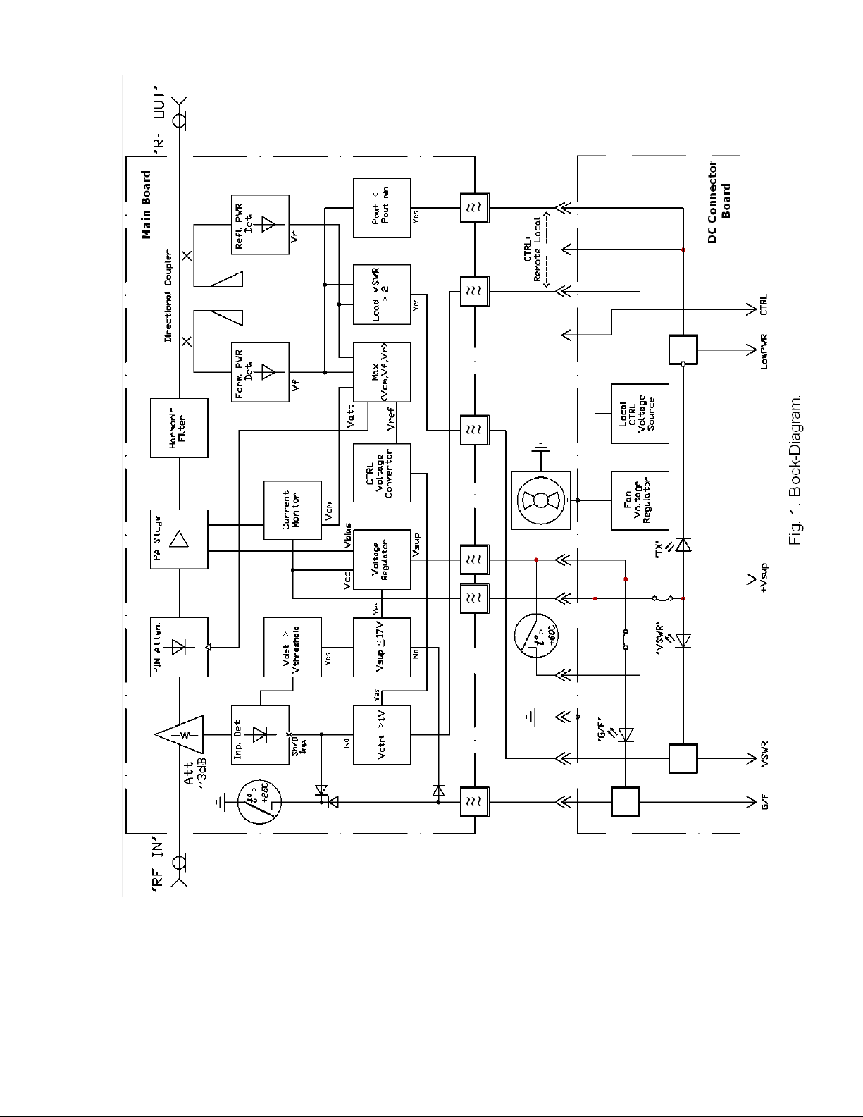
The PA module contains two PCB assemblies: the Main Board Assembly and the DC Connector
Board.
The Main Board is placed inside a shielded compartment and is fastened on the flat metal surface of
Main Plate. The heatsink is attached to the outer side of Main Plate, as well as the fan controlling
thermal switch.
The Main Board contains the RF circuits and the majority of DC circuits. The DC Connector Board
includes the LEDs, power control potentiometer, fan voltage regulator and three DC connectors. The
control, monitoring and supply lines between Main Board Assembly and the DC Connector Board are
3
 Loading...