

Page 1

NGT Transceiver
ASR
H F R A D I O C O M M U N I C A T I O N S
GETTING STARTED GUIDE
Page 2

No part of this guide may be reproduced, transcribed,
translated into any language or transmitted in any form
whatsoever without the prior written consent of Codan
Limited.
© Copyright 2004 Codan Limited.
Codan part number 15-04137-EN Issue 1, May 2004
®
and CALM® are registered trademarks of Codan
NGT
Limited. Other brand, product, and company names
mentioned in this document are trademarks or registered
trademarks of their respective holders.
The English version takes precedence over any translated
versions.
Page 3

Table of contents
Introduction
1 NGT transceiver compliance
Introduction. . . . . . . . . . . . . . . . . . . . . . . . . . . . . . . . . . . . . . . . . . . . . . . . . . 4
European Radio and Telecommunications Terminal Equipment
Directive . . . . . . . . . . . . . . . . . . . . . . . . . . . . . . . . . . . . . . . . . . . . . . . . . . . . 5
Electromagnetic compatibility and safety notices . . . . . . . . . . . . . . . . . . . . 7
FCC compliance . . . . . . . . . . . . . . . . . . . . . . . . . . . . . . . . . . . . . . . . . . . . . 10
2 Installation
NGT ASR mobile stations . . . . . . . . . . . . . . . . . . . . . . . . . . . . . . . . . . . . . . 12
NGT ASR fixed stations . . . . . . . . . . . . . . . . . . . . . . . . . . . . . . . . . . . . . . . 18
3 The handset
The channel screen . . . . . . . . . . . . . . . . . . . . . . . . . . . . . . . . . . . . . . . . . . . 28
4 Getting started
CODAN
Switching on the transceiver. . . . . . . . . . . . . . . . . . . . . . . . . . . . . . . . . . . . 32
Changing the screen contrast . . . . . . . . . . . . . . . . . . . . . . . . . . . . . . . . . . . 33
Changing the screen brightness . . . . . . . . . . . . . . . . . . . . . . . . . . . . . . . . . 34
Using the keys on the handset. . . . . . . . . . . . . . . . . . . . . . . . . . . . . . . . . . . 35
Accessing the Main Menu . . . . . . . . . . . . . . . . . . . . . . . . . . . . . . . . . . . . . 37
Switching scanning on or off . . . . . . . . . . . . . . . . . . . . . . . . . . . . . . . . . . . 38
Switching mute on or off . . . . . . . . . . . . . . . . . . . . . . . . . . . . . . . . . . . . . . 39
Entering your station self address. . . . . . . . . . . . . . . . . . . . . . . . . . . . . . . . 40
Listen Before Transmit Mode. . . . . . . . . . . . . . . . . . . . . . . . . . . . . . . . . . . 42
Replacing LQA information for all channels in an ALE/CALM
network . . . . . . . . . . . . . . . . . . . . . . . . . . . . . . . . . . . . . . . . . . . . . . . . . . . . 44
Making a manual sounding operation in an ALE/CALM
network . . . . . . . . . . . . . . . . . . . . . . . . . . . . . . . . . . . . . . . . . . . . . . . . . . . . 47
Selecting the best channel in an ALE/CALM network . . . . . . . . . . . . . . . 48
Making a Selective call from the Address List. . . . . . . . . . . . . . . . . . . . . . 49
NGT ASR Transceiver Getting Started Guide i
Page 4

Table of contents
Making a Phone call from the Address List . . . . . . . . . . . . . . . . . . . . . . . . 51
Making an emergency call using the emergency key . . . . . . . . . . . . . . . . . 53
Using a special ALE address syntax to make a call . . . . . . . . . . . . . . . . . . 55
Appendix A—Standard hot keys
Appendix B—Entering and editing text
Appendix C—Finding words and values
Appendix D—Creating an entry in a list
Appendix E—HF radio transmission
Appendix F—Definitions
Standards and icons . . . . . . . . . . . . . . . . . . . . . . . . . . . . . . . . . . . . . . . . . . . 79
Acronyms and abbreviations . . . . . . . . . . . . . . . . . . . . . . . . . . . . . . . . . . . . 80
Glossary . . . . . . . . . . . . . . . . . . . . . . . . . . . . . . . . . . . . . . . . . . . . . . . . . . . . 81
Units. . . . . . . . . . . . . . . . . . . . . . . . . . . . . . . . . . . . . . . . . . . . . . . . . . . . . . . 88
Unit multipliers . . . . . . . . . . . . . . . . . . . . . . . . . . . . . . . . . . . . . . . . . . . . . . 88
About this issue . . . . . . . . . . . . . . . . . . . . . . . . . . . . . . . . . . . . . . . . . . . . . . 89
Index
ii NGT ASR Transceiver Getting Started Guide
Page 5

List of figures
Figure 1: Typical NGT ASR mobile station. . . . . . . . . . . . . . . . . . 13
Figure 2: Typical NGT ASR fixed station . . . . . . . . . . . . . . . . . . . 18
Figure 3: The handset. . . . . . . . . . . . . . . . . . . . . . . . . . . . . . . . . . . 23
Figure 4: The channel screen in the Channel List . . . . . . . . . . . . . 28
Figure 5: The channel screen during a call . . . . . . . . . . . . . . . . . . 29
Figure 6: The scanning screen . . . . . . . . . . . . . . . . . . . . . . . . . . . . 29
Figure 7: The reflective properties of the ionosphere . . . . . . . . . . 74
CODAN
NGT ASR Transceiver Getting Started Guide iii
Page 6

List of figures
This page has been left blank intentionally.
iv NGT ASR Transceiver Getting Started Guide
Page 7

List of tables
Table 1: Earth symbols . . . . . . . . . . . . . . . . . . . . . . . . . . . . . . . . . . 9
Table 2: Cables for a typical NGT ASR mobile station . . . . . . . . 14
Table 3: Cables for a typical NGT ASR fixed station. . . . . . . . . . 19
Table 4: Features of the handset. . . . . . . . . . . . . . . . . . . . . . . . . . 24
Table 5: Standard hot keys on the handset . . . . . . . . . . . . . . . . . . 59
Table 6: Examples of channels and modes. . . . . . . . . . . . . . . . . . 75
Table 7: The phonetic alphabet. . . . . . . . . . . . . . . . . . . . . . . . . . . 78
CODAN
NGT ASR Transceiver Getting Started Guide v
Page 8

List of tables
This page has been left blank intentionally.
vi NGT ASR Transceiver Getting Started Guide
Page 9

Introduction
This guide provides instructions on how to connect up your
NGT ASR transceiver, and how to perform basic setup and
operating tasks. It assumes that you have limited knowledge of
HF communication and of using an HF radio.
This guide contains the following sections:
Section 1 NGT transceiver compliance—compliance
Section 2 Installation—explains briefly how to connect
Section 3 The handset—describes the handset and the
Section 4 Getting started—explains how to use the basic
Appendix A Standard hot keys—describes the standard hot
Appendix B Entering and editing text—describes how to
CODAN
information and safety notices
the components of your transceiver
function of each key on the handset
operating features of your transceiver
keys on the handset
enter and edit text in editable screens
Appendix C Finding words and values—describes how to
find words and values using the key
Appendix D Creating an entry in a list—describes how to
create an entry in the Address List, Channel
List, Network List, NET List and Phone Link
List
Appendix E HF radio transmission—describes the medium
of HF communication and how to use it
effectively
Appendix F Definitions—explains the terms and
abbreviations used in this guide
There is an index at the end of this guide and a CD containing
extensive reference material.
NGT ASR Transceiver Getting Started Guide 1
Page 10

Introduction
Accessing the CD
To access the CD:
1 Place the CD in the CD drive of your computer.
The CD should automatically launch the NGT ASR
Transceiver Reference Manual as a fully text-searchable
HTML help file.
2NGT ASR Transceiver Getting Started Guide
Page 11

1 NGT transceiver compliance
This section contains the following topics:
Introduction (4)
European Radio and Telecommunications Terminal
Equipment Directive (5)
Electromagnetic compatibility and safety notices (7)
FCC compliance (10)
CODAN
NGT ASR Transceiver Getting Started Guide 3
Page 12

NGT transceiver compliance
Introduction
This section describes how to ensure the NGT transceiver
complies with the European Electromagnetic Compatibility
Directive 89/336/EEC and the European Low Voltage
Directive 73/23/EEC as called up in the European Radio and
Telecommunications Terminal Equipment Directive
1999/5/EC.
This section also contains the requirements for FCC
compliance.
4NGT ASR Transceiver Getting Started Guide
Page 13

NGT transceiver compliance
European Radio and Telecommunications Terminal Equipment Directive
The NGT transceiver product range has been tested and
complies with the following standards and requirements
(articles of the R&TTE Directive):
• Article 3.1b: ETSI EN 301 489-1
• Article 3.1b: ETSI EN 301 489-15
• Article 3.2: Australian type approval according to
AZ/NZS 4770:2000 and ECR 209
• Article 3.1a: Assessed against ICNIRP and FCC
requirements
• Article 3.1a: EN 60950
Compliance with these standards is deemed sufficient to fulfil
the requirements of the Radio and Telecommunications
Terminal Equipment Directive 1999/5/EC.
Product marking and labelling
Any equipment supplied by Codan that satisfies these
requirements is identified by the , or
markings on the model label of the product.
Declaration of Conformity and Expert Letter of Opinion
The CE Declarations of Conformity and Expert Letter of
Opinion for each specific product are listed on page 89,
Associated documents. These documents can be made
available upon request to Codan or a Codan-authorised
supplier.
NGT ASR Transceiver Getting Started Guide 5
0191 0191
Page 14

NGT transceiver compliance
Protection of the radio spectrum
CAUTION
Most countries restrict the use of HF radio
communications equipment to certain frequency
bands and/or require such equipment to be
licensed. It is the user’s responsibility to check
the specific requirements with the appropriate
communications authorities. If necessary,
contact Codan for more information.
6NGT ASR Transceiver Getting Started Guide
Page 15

NGT transceiver compliance
Electromagnetic compatibility and safety notices
Radiation safety
To ensure optimal transceiver performance and to avoid
exposure to excessive electromagnetic fields, the antenna
system must be installed according to the instructions
provided.
WARNING
WARNING
Electromagnetic compatibility
To ensure compliance with the EMC Directive is maintained,
you must:
Do not touch the antenna while it is
transmitting.
You should not transmit from your transceiver if
people are within:
• 1.5 m of any part of a mobile antenna
• 2 m of any part of a fixed antenna in a data
installation with < 125 W output
• 5 m of any part of a fixed antenna in a data
installation with < 1 kW output
1 Use standard shielded cables supplied from Codan
(where applicable).
1 Ensure the covers for the equipment are fitted correctly.
If it is necessary to remove the covers at
CAUTION
any stage, they must be refitted correctly
before using the equipment.
1 Cover unused connectors on the junction box and RF
unit with the protective caps supplied to prevent
electrostatic discharge passing through your NGT
equipment.
NGT ASR Transceiver Getting Started Guide 7
Page 16

NGT transceiver compliance
Electrical safety
To ensure compliance with the European Low Voltage
Directive is maintained, you must install and use the
NGT transceiver in accordance with the instructions in the
NGT ASR Transceiver Getting Started Guide and the NGT
ASR Transceiver Reference Manual.
When using equipment that is connected directly to the AC
mains these precautions must be followed and checked before
apply AC power to the unit:
1 Use the standard AC mains cable supplied.
1 Ensure the covers for the equipment are fitted correctly.
CAUTION
WARNING
If it is necessary to remove the covers at
any stage, they must be refitted correctly
before using the equipment.
A protective earth connection must be
included in the mains wiring to the 3020
Transceiver Supply (see page 8, Earth
symbols).
The protective cover must always be fitted
when the 3020 Transceiver Supply is
connected to the AC mains.
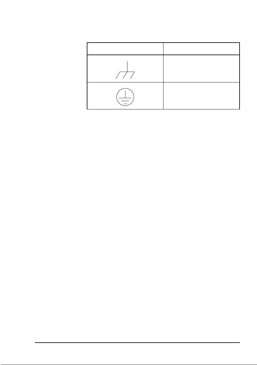
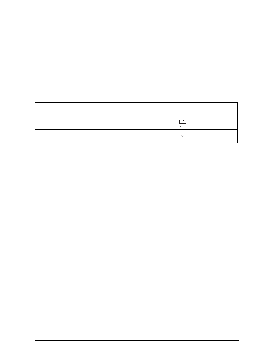
Earth symbols
Chassis earth connection points have been provided on the
NGT transceiver and 3020 Transceiver Supply. A protective
earth is provided in the AC mains wiring of the 3020
Transceiver Supply. This protective earth needs to be
connected at the AC mains supply outlet. The symbols shown
in Tabl e 1 are used to identify the earths on the equipment.
8NGT ASR Transceiver Getting Started Guide
Page 17
NGT transceiver compliance
Table 1: Earth symbols
Symbol Meaning
Chassis earth
Protective earth
NGT ASR Transceiver Getting Started Guide 9
Page 18

NGT transceiver compliance
FCC compliance
FCC Part 90 certification
The NGT ASR transceiver has been tested and certified to FCC
Part 90 (FCC identifier code DYYNGT-2).
FCC Part 15 compliance
Any modifications made to the NGT transceiver and 3020
Transceiver Supply that are not approved by the party
responsible for compliance may void your equipment’s
compliance under Part 15 of the FCC rules.
The NGT transceiver and 3020 Transceiver Supply have been
tested and found to comply with the limits for a Class B
device, pursuant to Part 15 of the FCC rules. These limits are
designed to provide reasonable protection against harmful
interference in a residential installation. This equipment
generates, uses and can radiate radio frequency energy and, if
not installed and used in accordance with the instructions, may
cause harmful interference to radio communications.
However, there is no guarantee that interference will not occur
in a particular installation. If this equipment does cause
harmful interference to radio or television reception, which
can be determined by switching the equipment off and on, the
user is encouraged to try to correct the interference by one or
more of the following measures:
• reorient or relocate the receiving antenna
• increase the separation between the equipment and
receiver
• connect the equipment into an outlet on a circuit different
from that to which the receiver is connected
• consult the dealer or an experienced radio/TV technician
for help
10 NGT ASR Transceiver Getting Started Guide
Page 19

2Installation
This section contains the following topics:
NGT ASR mobile stations (12)
NGT ASR fixed stations (18)
CODAN
NGT ASR Transceiver Getting Started Guide 11
Page 20

Installation
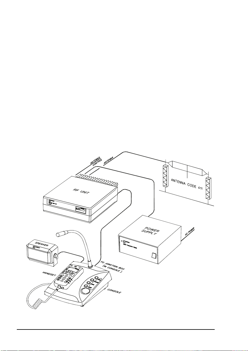
NGT ASR mobile stations
An NGT ASR mobile station typically consists of:
• a handset and cradle
• a junction box
• a speaker
• an RF unit and vehicle mounting cradle (includes DC
power cable)
• a 12 V DC power supply (battery)
• an automatic tuning antenna
Figure 1 on page 13 shows a typical NGT ASR mobile station.
12 NGT ASR Transceiver Getting Started Guide
Page 21
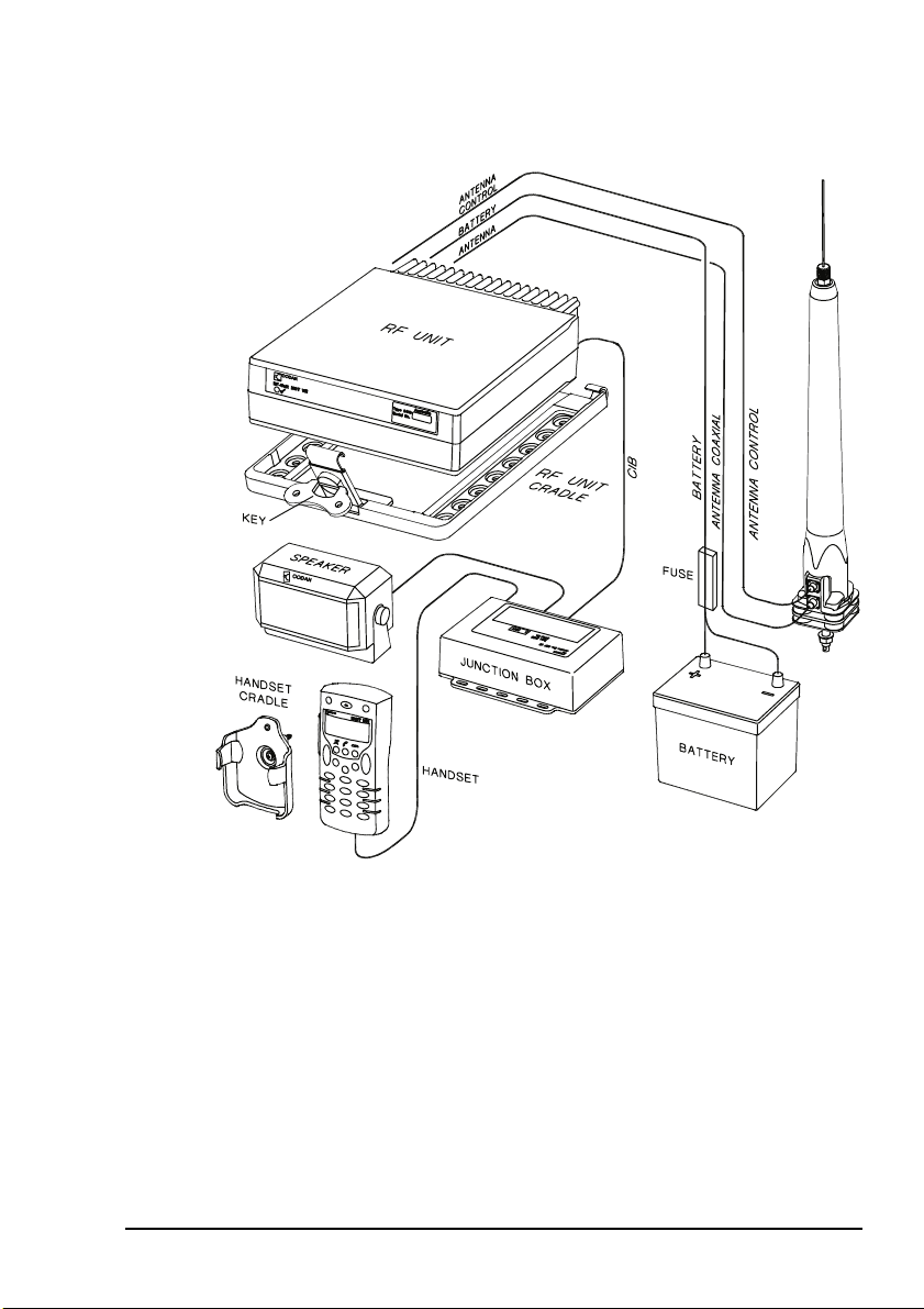
Figure 1: Typical NGT ASR mobile station
Installation
9350 ANTENNA
NGT ASR Transceiver Getting Started Guide 13
Page 22
Installation
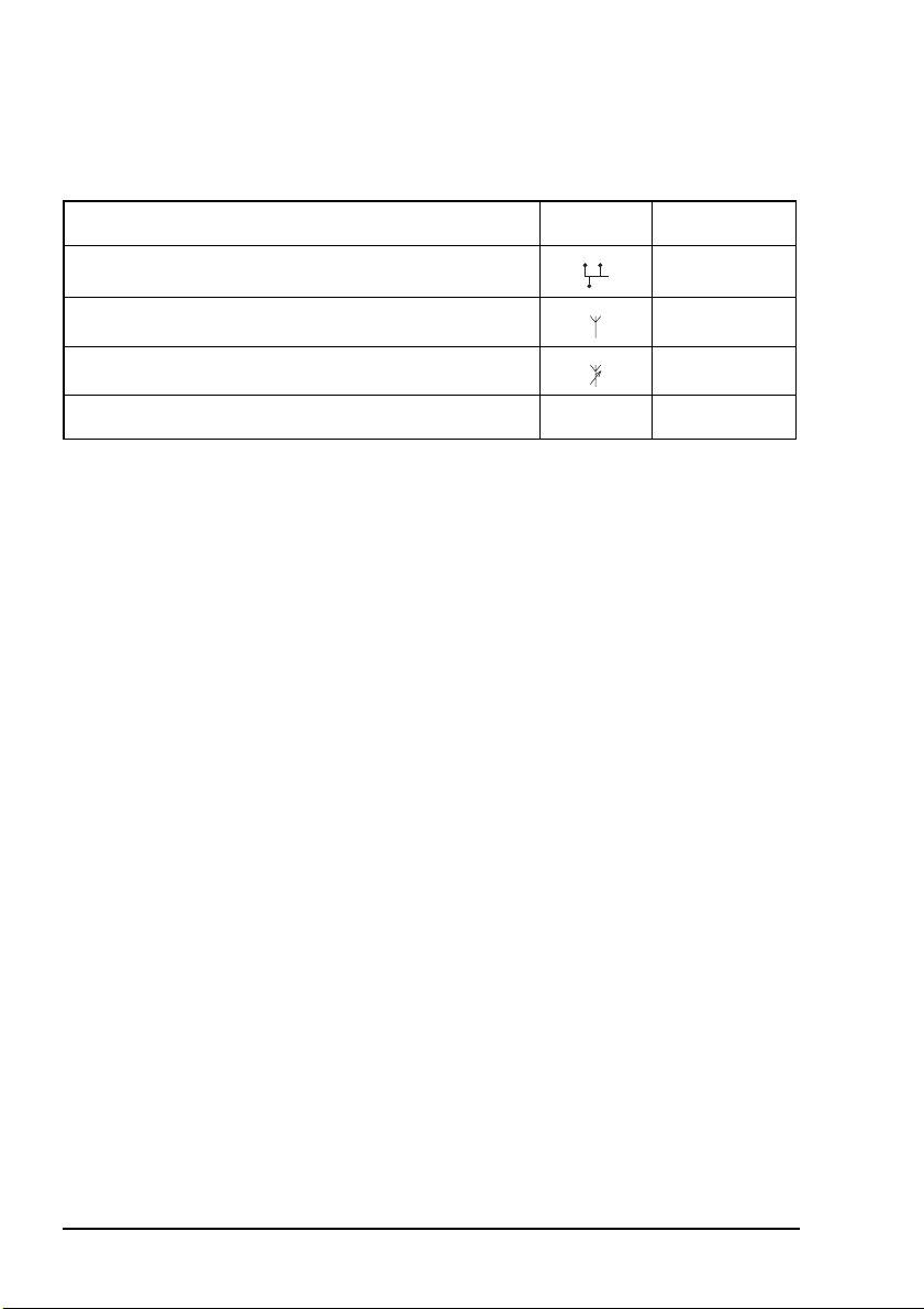
Cables
Table 2: Cables for a typical NGT ASR mobile station
Cable Symbol Part number
CIB cable between RF unit and junction box 08-05610-006
Coaxial cable between RF unit and antenna 08-05103-006
Control cable between RF unit and antenna 08-05627-006
DC power supply cable 08-03255
a. The part number corresponds to a standard 6 m cable. The cables are also available in a number
of shorter and longer lengths.
Mounting an NGT ASR mobile station
Most components of an NGT ASR mobile station are provided
with their own mounting cradles. For general guidance on
suitable locations for equipment and installing these stations
see the reference material on the enclosed CD.
Mounting the handset cradle
To mount the handset cradle:
a
1 Mount the handset according to the fitting instructions
(Codan part number 15-00129-001) provided with the
handset cradle.
14 NGT ASR Transceiver Getting Started Guide
Page 23

Installation
Mounting the speaker
To mount the speaker:
1 Secure the mounting cradle to the surface with at least
two screws.
Ensure there is sufficient space at the rear for the cable.
1 Attach the speaker to the cradle with the two screws and
rubber washers.
Mounting the junction box
To mount the junction box:
1 Use cable ties or screws to secure the junction box in a
suitable location.
Mounting the RF unit
If you are transferring a fixed station to a mobile
station and you have installed rubber feet to the
WARNING
bottom of the RF unit, you must remove the
rubber feet before installing it into the mounting
cradle.
The cradle can be mounted in any position that allows the RF
unit to be inserted into the cradle.
To mount the RF unit:
1 Secure the mounting cradle to the surface with at least
four screws, one in each corner of the cradle.
NOTE
Ensure there is sufficient space at the rear
of the cradle to clear the RF unit heatsink.
1 If the key is locked to the base of the cradle, flip the key
away from the base until it can be rotated (see
Figure 1 on page 13), then rotate the key in a
counterclockwise direction.
NGT ASR Transceiver Getting Started Guide 15
Page 24
Installation
1 Place the RF unit into the cradle and push it under the
tabs at the rear of the cradle, then hold the clamp against
the front of the RF unit.
1 Rotate the key clockwise, then push the key toward the
base of the cradle to lock the RF unit into position.
Connecting an NGT ASR mobile station
Connecting an NGT ASR mobile station
If you are installing a VP-116 Voice Privacy
Unit, you will have been supplied with an
NOTE
To connect an NGT ASR mobile station:
Encryptor Interface junction box. The VP-116
connects to the 15-way Encryptor connector
().
1 Connect the plug of the handset cable to the socket on
the junction box, then secure the locking ring tightly into
position.
1 Connect the plug at the end of the speaker cable to the
socket on the junction box.
1 Connect the socket at the end of the cable to the plug
at the end of the cable lead from the RF unit, then
secure the locking ring tightly into position.
1 Connect the socket at the opposite end of the cable to
the plug on the junction box, then secure the locking
ring tightly into position.
1 Connect the plug at the end of the cable to the socket at
the end of the cable lead from the RF unit, then secure
the locking ring tightly into position.
1 Connect the plug at the opposite end of the cable to the
socket located at the base of the antenna, then secure the
locking ring tightly into position.
16 NGT ASR Transceiver Getting Started Guide
Page 25

Installation
Connecting the control cable to an automatic tuning antenna
To connect the control cable:
1 Connect the socket at the end of the cable into the plug
at the base of the antenna, then secure the locking ring
tightly into position.
1 Fit the plug at the opposite end of the cable into the
socket at the end of the lead from the RF unit.
Connecting the power supply
To connect the transceiver to the battery power supply:
1 Connect the power supply cable (Codan part number
08-03255) to the plug at the end of the 12 V cable lead
from the RF unit.
1 Route the power supply cable according to the
instructions supplied with the Vehicle Installation Kit
(Codan part number 15-00112).
1 Insert the 32 A fuse and holder in the power supply cable
at a convenient location, as close as possible to the
battery terminals.
1 Connect the power supply cable to the battery terminals,
black to negative, red to positive.
Connecting ancillary equipment
The NGT ASR mobile transceiver system uses the junction box
for connecting to ancillary equipment.
NGT ASR Transceiver Getting Started Guide 17
Page 26
Installation
NGT ASR fixed stations
An NGT ASR fixed station typically consists of:
• a desk console, containing a handset, a goose neck
microphone, a junction box, and a speaker
•an RF unit
• an AC transceiver supply
• a suitable fixed antenna (see the reference material on the
enclosed CD)
Figure 2 shows a typical NGT ASR fixed station.
Figure 2: Typical NGT ASR fixed station
18 NGT ASR Transceiver Getting Started Guide
Page 27
Installation
The junction box is fitted inside the desk
NOTE
console. The connectors on the junction box are
at the rear of the desk console.
Cables
Table 3: Cables for a typical NGT ASR fixed station
Cable Symbol Part number
CIB cable between RF unit and console
a
08-05610-006
Coaxial cable between RF unit and antenna
a. The part number for this cable corresponds to a 6 m CIB cable. The cable is also available in a
number of shorter or longer lengths.
b. The part number for this cable corresponds to a 30 m coaxial cable. The cable is also available
in a number of shorter lengths.
b
08-05103-030
Mounting an NGT ASR fixed station
An NGT ASR fixed station is most commonly mounted using a
desk console (Codan part number 15-10471). For general
guidance on suitable locations for equipment and installing the
fixed station see the reference material on the enclosed CD.
Desk console
The pre-assembled desk console combines a handset, a goose
neck microphone, a junction box, an in-built speaker and a
headphone jack (see Figure 2 on page 18).
NGT ASR Transceiver Getting Started Guide 19
Page 28

Installation
RF unit and transceiver supply
The RF unit and the transceiver supply are self-contained and
are usually stacked loosely. If you want to mount the RF unit
and/or the transceiver supply, contact your Codan
representative to obtain a rack-mounting unit or the
appropriate mounting cradles.
Rack-mounting unit
A rack-mounting unit consists of a 19 inch rack tray. It can be
used in conjunction with a desk console to mount your fixed
station. If you do not have a desk console, a cradle is available
for mounting the handset on the front panel of the rack unit.
Mounting cradles
WARNING
If you are mounting an RF unit in a cradle, do
not fit rubber feet to the bottom of the RF unit.
If you are transferring a mobile station to a fixed
station, and you are not mounting the RF unit in
NOTE
a cradle, rubber feet can be fitted to the bottom
of the RF unit. The rubber feet are available
from Codan (Codan part number
30-11208-000).
If you want to mount components of your fixed station
separately, customised mounting cradles exist for each
component. Mounting cradles are not commonly used in an
NGT fixed station, but they are available as options (see the
reference material on the enclosed CD).
20 NGT ASR Transceiver Getting Started Guide
Page 29
Connecting an NGT ASR fixed station
Installation
NOTE
NOTE
To connect an NGT ASR fixed station:
The handset is supplied connected to the desk
console.
If you are installing a VP-116 Voice Privacy
Unit, you will have been supplied with an
Encryptor Interface junction box. The VP-116
connects to the 15-way Encryptor connector
().
1 Connect the socket at the end of the cable to the plug
at the end of the cable lead from the RF unit, then
secure the locking ring tightly into position.
1 Connect the socket at the opposite end of the cable to
the plug at the rear of the desk console, then secure
the locking ring tightly into position.
1 Connect the plug at the end of the cable to the socket at
the end of the cable lead from the RF unit, then secure
the locking ring tightly into position.
1 Connect the plug at the opposite end of the cable to the
socket located at the base of the antenna, then secure the
locking ring tightly into position.
Connecting an automatic tuner to the RF unit and antenna (optional)
You may need to install a tuner to improve the
NOTE
NOTE
NGT ASR Transceiver Getting Started Guide 21
efficiency of the antenna in your fixed station
(see the reference material on the enclosed CD).
The tuner used in most applications has
connectors at the end of the cables attached to
the tuner, as described below. However, you
may have a tuner that has sockets on the
connector panel of the tuner.
Page 30

Installation
To connect the tuner to the RF unit:
If the connectors at the end of the control cables
from the RF unit and tuner are incompatible,
NOTE
you may require an NGT adaptor cable (Codan
part number 08-05655-001) to connect the tuner
to the RF unit.
1 Connect the plug at the end of the coaxial cable from the
tuner to the socket at the end of the cable lead from the
RF unit, then secure the locking ring tightly into position.
1 Connect the plug at the end of the control cable from the
tuner to the socket at the end of the cable lead from the
RF unit, then secure the locking ring tightly into position.
1 Connect the antenna to the antenna connection on the
tuner, then secure it tightly into position.
Connecting the transceiver supply
To connect the transceiver to the transceiver supply:
1 Connect the DC output from the transceiver supply to the
plug at the end of the 12 V cable lead from the RF unit.
1 Connect the transceiver supply to the AC mains supply.
22 NGT ASR Transceiver Getting Started Guide
Page 31

3 The handset
Figure 3: The handset
1
2
CODAN
26
10
11
3
4
MUTE CALL SCAN
5
6
7
8
9
1
4
*
TUNE
7
EASI
TALK
QZ
GHI
PRS
SV
2
5
8
0
CLAR
ABC
HELP
JKL
SEC
TUV
VIEW
3
6
9
#
MODE
DEF
MNO
WXY
CALL
LOGS
25
24
23
22
21
20
19
18
17
16
15
14
13
12
NGT ASR Transceiver Getting Started Guide 23
Page 32
The handset
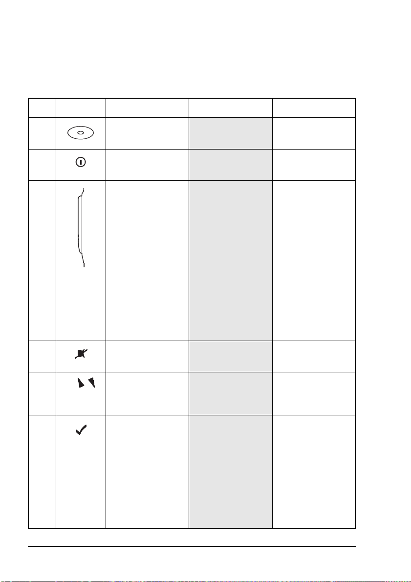
Tabl e 4 explains the features of the handset and the tasks they
enable you to perform.
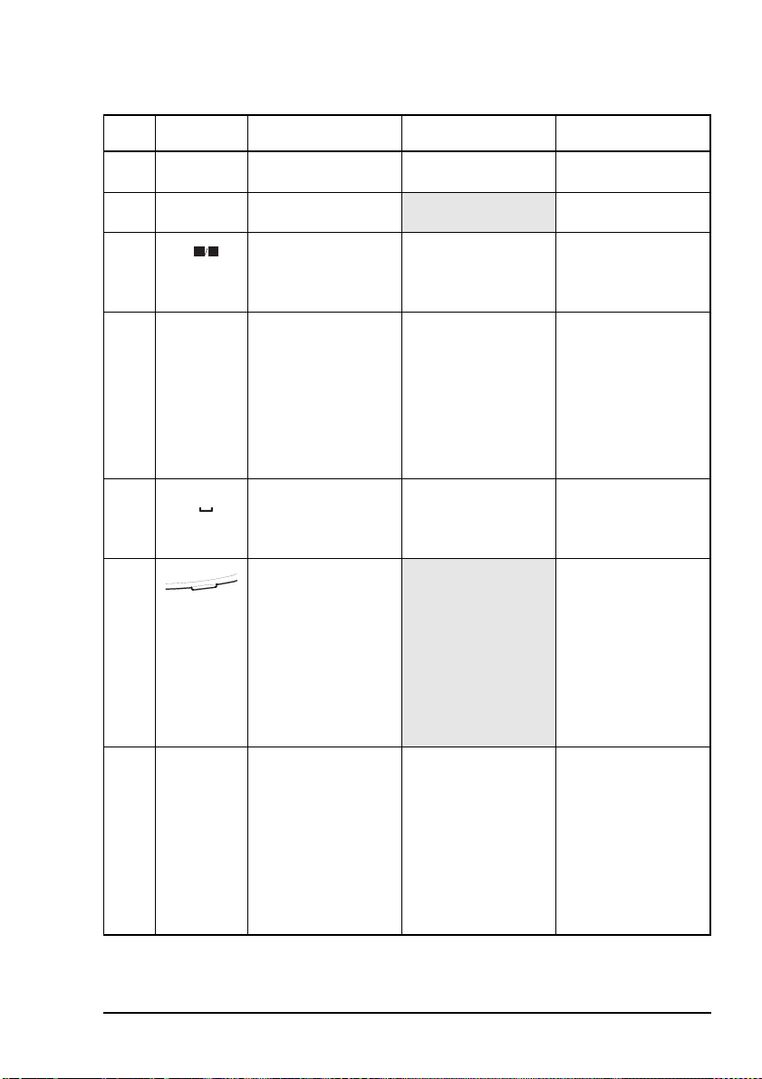
Table 4: Features of the handset
No. Feature Name Hot key function Normal function
1 Microphone
2Power
On/Off key
3 Press-to-talk button
4Mute key
5
Scroll keys scroll through items
speak to other
stations
switch power to the
transceiver on or off
communicate
during voice calls,
switch mute off,
cancel voice calls
prior to the point
where voice can be
transmitted, cancel
calls where data is
being transmitted,
and exit out of
editable screens
without saving
changes
switch mute on or
off
in a list and scroll
over text on a line
6Tick key
navigate down
through lists, select
items in lists, edit
settings, save
changes, send a
message in a call (if
enabled), and
answer ‘yes’ to
prompts
24 NGT ASR Transceiver Getting Started Guide
Page 33
The handset
E
Q
Table 4: Features of the handset (cont.)
No. Feature Name Hot key function Normal function
7 1QZ key Go to Manual Tune enter 1, Q and Z
8 4GHI key
9 7PRS key Toggles between
1
4
7
TUN
GHI
PRS
Z
enter 4, G, H and I
SV
enter 7, P, R and S
Selcall mute and
Voice mute
10 Asterisk key Toggles Easitalk on
*
EASI
or off
enter the upper-case
text (A) punctuation
marks . , ’ ? ! & # $
* ( ) - + / in editable
text screens, and
enter @ ? , in
address screens
11 Zero space key Toggles between
0
VIEW
Channel List and
enter 0 and a space
Address List
12 Programming jack
use a programming
cable and a PC on
which NSP
software has been
installed to
upload/download
information to/from
the transceiver
13 Hash key Go to Calls Out
#
CALL
LOGS
Log, Calls In Log,
Last Heard Log,
then return to the
screen from which
you began
display the Calls
Out, Calls In, and
Last Heard Logs,
and toggle between
upper-case, lower-
case and numeric
characters when
entering text
NGT ASR Transceiver Getting Started Guide 25
Page 34

The handset
P
E
Table 4: Features of the handset (cont.)
No. Feature Name Hot key function Normal function
14 8TUV key Toggles VP-116 or
SEC
8
TUV
Voice Encryptor on
enter 8, T, U and V
or off, if installed
15 9WXY key
16 5JKL key Toggles Help Mode
17 6MNO key
18 2ABC key Go to Clarifier enter 2, A, B and C
19 3DEF key Selects USB, LSB
9
5
6
2
3
WXY
HEL
JKL
MNO
CLAR
ABC
MOD
DEF
on or off
or AM (if available)
20 Cross key
enter 9, W, X and Y
enter 5, J, K and L
enter 6, M, N and O
enter 3, D, E and F
navigate up through
lists, backspace
over text, remove
messages on the
screen, cancel
changes, display the
home screen, and
answer ‘no’ to
prompts
21 Find key
display the Find
prompt, open the
List Manager, and
select the best
channel for an ALE
call
22 Volume up/down
keys
increase or decrease
the volume of the
speaker
26 NGT ASR Transceiver Getting Started Guide
Page 35
The handset
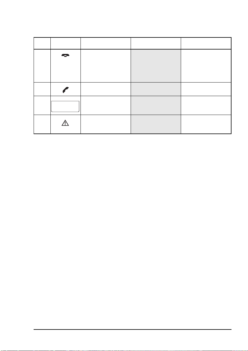
Table 4: Features of the handset (cont.)
No. Feature Name Hot key function Normal function
23 Hangup/Scan key end a call if a call is
in progress, or
toggle scanning on
or off
24 Call key
25 Handset screen
26 Emergency key
start a call
view the status of
the transceiver
begin an emergency
call
NGT ASR Transceiver Getting Started Guide 27
Page 36
The handset
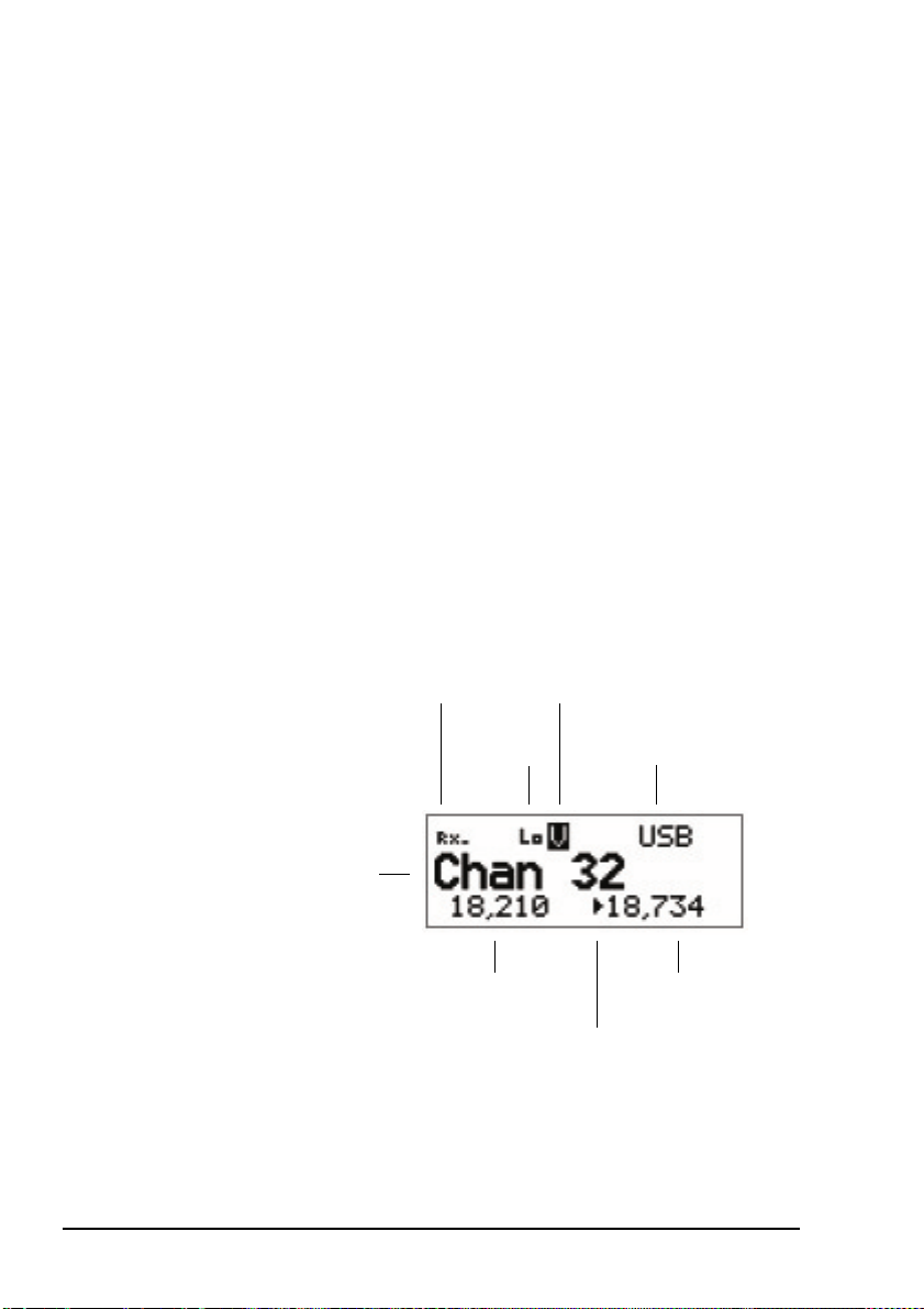
The channel screen
The channel screen is displayed when you open the Channel
List. It displays:
• the name of the currently selected channel
• a bar graph that indicates the signal strength on receive
and the output power on transmit
• the power level indicator
• the mode
• the transmit and receive frequencies, if applicable
• an arrow that indicates whether the transceiver is
receiving or transmitting
Figure 4: The channel screen in the Channel List
signal
strength/output
power indicator
channel name
Tx freq in kHz
28 NGT ASR Transceiver Getting Started Guide
power
indicator
mute type
and status
indicator
mode
Rx freq in kHz
Rx/Tx indicator
Page 37

The handset
If the transmit and receive frequencies are the same, the
frequency is only displayed in the receive frequency position
on the right side of the screen and the Rx indicator arrow is not
used. The signal strength/output power indicator shows
whether the transceiver is receiving or transmitting.
While a call is being established, the transceiver will show that
calling activity is in progress by flashing the icon in place
of the scan indicator.
During a call the scan indicator is replaced with an icon that
indicates the type of call being sent or received.
Figure 5: The channel screen during a call
call type icon
When the transceiver is scanning the channel screen is
replaced by the scanning screen.
Figure 6: The scanning screen
NGT ASR Transceiver Getting Started Guide 29
Page 38

The handset
E
Selecting a channel
To select a channel:
1 Go to the Channel List.
1 Scroll through the channels in the list. Stop scrolling
1 Press the key to return to the Main Menu.
when the channel you want is displayed.
The channel is selected.
If you want to change the mode, press the
MOD
key. If the mode does not change
3
DEF
there is only one mode for the channel.
You can also use the Find feature to find a
NOTE
channel (see page 67, Finding words and
values).
If you have an automatic antenna fitted,
press the PTT button to tune the antenna to
the currently selected channel.
30 NGT ASR Transceiver Getting Started Guide
Page 39

4 Getting started
This section contains the following topics:
Switching on the transceiver (32)
Changing the screen contrast (33)
Changing the screen brightness (34)
Using the keys on the handset (35)
Accessing the Main Menu (37)
Switching scanning on or off (38)
Switching mute on or off (39)
Entering your station self address (40)
Listen Before Transmit Mode (42)
Replacing LQA information for all channels in an
ALE/CALM network (44)
Making a manual sounding operation in an ALE/CALM
network (47)
Selecting the best channel in an ALE/CALM network (48)
CODAN
Making a Selective call from the Address List (49)
Making a Phone call from the Address List (51)
Making an emergency call using the emergency key (53)
Using a special ALE address syntax to make a call (55)
You should not transmit from your transceiver if
people are standing within:
• 1.5 m of a mobile antenna
WARNING
NGT ASR Transceiver Getting Started Guide 31
• 2 m of a fixed antenna in a data installation
with < 125 W output
• 5 m of a fixed antenna in a data installation
with < 1 kW output
Page 40

Getting started
Switching on the transceiver
To switch on the transceiver:
1 Press the key.
If you are prompted to enter a password, enter your user
or administrator password then press the key.
If you enter an incorrect password it is automatically
erased. If you enter an incorrect password three times the
transceiver automatically switches off.
Switching off the transceiver
To switch off the transceiver:
1 Hold the key down for two seconds then release.
The transceiver is switched off.
32 NGT ASR Transceiver Getting Started Guide
Page 41

Changing the screen contrast
To change the contrast of the screen:
Getting started
1 Press + to access the Screen Contrast entry in
the Control List.
The Screen Contrast slider screen is displayed.
9
WXY
1 Use the or key to increase or decrease the contrast.
1 Press the key to save the value.
1 Press the key repeatedly until you return to the Main
Menu.
NGT ASR Transceiver Getting Started Guide 33
Page 42
Getting started
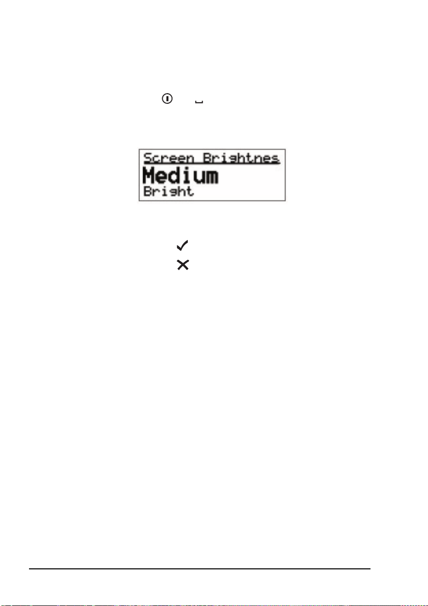
Changing the screen brightness
To change the brightness of the screen:
VIEW
1 Press + to access the Screen Brightness entry
in the Control List.
The screen brightness setting is displayed.
0
1 Scroll through the values until the one you want is
displayed on the active line.
1 Press the key to save the value.
1 Press the key repeatedly until you return to the Main
Menu.
If the Screen Auto-Dim entry in the Control List
NOTE
is enabled then the brightness drops one level
after the specified time.
34 NGT ASR Transceiver Getting Started Guide
Page 43

Using the keys on the handset
Detailed information on the function of the keys
NOTE
There are two ways to use the keys on the handset. You can:
•press a key
• hold a key
Pressing a key means to press a key until the handset makes a
short beep sound, then release the key.
Holding a key means to press and hold a key until the handset
makes a short beep followed by a higher pitched beep, then
release the key.
on the handset is provided on page 23, The
handset and page 59, Standard hot keys.
Getting started
NOTE
The two actions perform different functions. The instructions
in this guide specify whether you need to press or hold a key
to perform a task.
The scroll keys
The and keys are the scroll keys. Use these keys to scroll
up or down through any kind of list, to scroll left or right over
text, and to increase or decrease a value.
The and keys
The and keys are context sensitive: their functions
change according to the task you are performing. For example,
to select an item and navigate down through the lists in the
transceiver, press the key. To navigate up through the lists,
press the key. To edit a setting, hold the key. To discard
your changes, hold the key.
The keys will only beep if the Key Beep entry in
the Control List is set to On.
NGT ASR Transceiver Getting Started Guide 35
Page 44

Getting started
Press the key to:
• navigate down from the Main Menu to entries and then
to settings by selecting the item on the active line in the
list
• save changes
• answer ‘yes’ to prompts
Hold the key to edit settings.
Press the key to:
• navigate up from settings to entries and then to the Main
Menu
• backspace over text
• remove messages on the screen
• cancel changes
• answer ‘no’ to prompts
Hold the key to go from any location to the home screen,
and from the home screen to the Main Menu. If you have
entered text into a setting and want to discard the changes you
made, hold the key.
36 NGT ASR Transceiver Getting Started Guide
Page 45

Accessing the Main Menu
The Main Menu is easily accessed from the home screen. The
home screen may be any screen that you choose however, by
default the home screen is the channel screen. For information
on setting the home screen see the reference material on the
enclosed CD.
To access the home screen from any other screen:
1 Hold the key.
To access the Main Menu from the home screen:
1 Press the key.
Getting started
NGT ASR Transceiver Getting Started Guide 37
Page 46

Getting started
Switching scanning on or off
To switch scanning on or off:
1 Press the key.
If a call is not in progress, scanning is toggled on or off.
If a call is in progress, the call is ended.
If the transceiver was scanning before the call was sent
or received, it resumes scanning. If the transceiver was
not scanning before the call, press the key to switch
scanning on.
When scanning is switched on mute is also
NOTE
Pausing scanning
switched on.
You cannot use the PTT button while the
transceiver is scanning.
To pause scanning:
1 Do one of the following:
• to pause scanning on the current channel/mode, press
the key
• to pause scanning and scroll to another channel/mode,
press the or key
The channel/modes through which you can scroll are
those in the networks that were being scanned. They are
not listed alphabetically but in the order in which they
were being scanned.
If you do not press a key within 30 seconds the
transceiver automatically resumes scanning.
1 While scanning is paused, do one or more of the
following:
• to converse, hold down the PTT button
• to resume scanning immediately, press the key
38 NGT ASR Transceiver Getting Started Guide
Page 47

Switching mute on or off
To switch mute on or off:
1 Press the key.
A message is displayed briefly to inform you that mute
has been switched on or off.
When the channel screen is displayed the mute status is
indicated by a V or S at the top centre of the screen. If the
letter is highlighted, mute is on. If the letter is not
highlighted, mute is off.
Setting the mute type
To select the mute type:
1 Press the key to toggle the mute type between
Voice mute (V) and Selcall mute (S).
SV
7
PRS
Getting started
NGT ASR Transceiver Getting Started Guide 39
Page 48

Getting started
Entering your station self address
To enter your station self address:
1 Go to the Address entry in the Control List.
1 Select the entry.
If a self address has not yet been entered the screen
displays (none). Press the key to open the List
Manager.
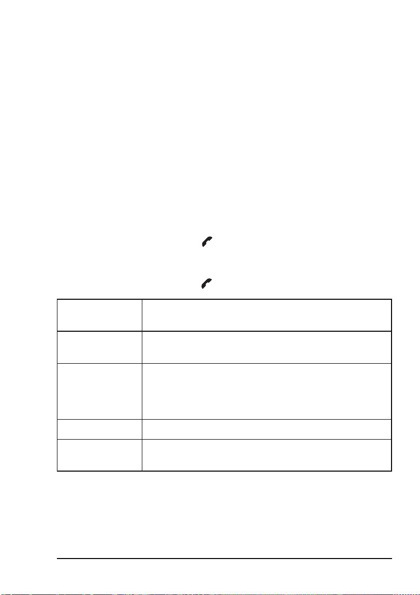
If one or more self addresses have already been entered
the screen displays the number of addresses (e.g.
1 items). Press the key to display the self addresses,
then hold the key to open the List Manager.
1 Select Add item.
1 Enter the self address of your station. For example:
NOTE
40 NGT ASR Transceiver Getting Started Guide
For help with entering text see page 61,
Entering and editing text.
Page 49
Getting started
Enter up to 15 upper-case letters or numbers, or a
combination of both. ALE addresses are sent in groups of
3 characters. You should use addresses with a length that
is a multiple of 3, but preferably just 3 characters.
1 Press the key.
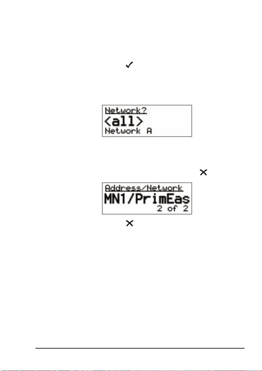
1 Select the network in which you want to use this self
address.
To use the self address in all networks, select <all>.
The self address is created and the List Manager remains
open.
1 If you want to view the self address you have created,
close the List Manager by pressing the key.
1 Press the key repeatedly until you return to the Main
Menu.
NGT ASR Transceiver Getting Started Guide 41
Page 50

Getting started
Listen Before Transmit Mode
If you change the setting in the Cfg LBT Mode
NOTE
The NGT transceiver is capable of listening to a channel
before initiating a call on the channel. If the Cfg LBT Mode in
the Control List is enabled, the transceiver will detect whether
or not there is traffic on the selected channel, i.e. the channel is
occupied. The transceiver will listen on a channel for the
length of time specified in the Cfg LBT Period entry in the
Control List. The transceiver will try busy channels twice
before reporting that they are busy.
The Cfg LBT Mode may be set to Enabled, Override allowed,
or Disabled.
When the Cfg LBT Mode is set to Enabled, and the
transceiver detects that the channel(s) tried is(are) busy, it will
prompt you to try the call again. You can:
entry in the Control List you must switch the
transceiver off then on again for the change to
take effect.
• press the key to try the call again using LBT
• press the key to select a new channel, then press the
key to make a call on this channel using LBT
If only one channel was tried and found to be
NOTE
42 NGT ASR Transceiver Getting Started Guide
busy using LBT, you can listen for traffic on the
channel then, if clear, override LBT by holding
the key.
Page 51

Getting started
When the Cfg LBT Mode is set to Override allowed, and the
transceiver detects that the channel(s) tried is(are) busy, it will
prompt you to try the call again. You can:
• press the key to try the call again using LBT
• hold the key to try the call again without LBT (send
the call regardless of any detected traffic)
• press the key to select a new channel, then press the
key to make a call on this channel using LBT
• hold the key to select a new channel and try the call
on this channel without LBT (send the call regardless of
any detected traffic)
Calls using the Emergency call type or calls made through the
key will override the LBT Mode if it is enabled at either
level.
NOTE
For information on setting up the key see
the reference material on the enclosed CD.
NGT ASR Transceiver Getting Started Guide 43
Page 52

Getting started
Replacing LQA information for all channels in an ALE/CALM network
You cannot make a Channel Test call using the
CAUTION
If your station operates in a rapidly changing environment,
e.g. interactions with mobile stations, you may want to replace
the LQA information in the relevant part of the database for
the channels in an ALE/CALM network just prior to making a
call in the network. You can do this by making a Channel Test
call in the network using the Group Selective or NET address
syntaxes.
During a Channel Test call in an ALE/CALM network the
LQA screen will be visible, indicating the most recent
response from a station, and a progress report on the highest
number of responses received on any channel and the number
of channels tried.
ALL, ANY or Wildcard address syntaxes, or to
a NET that is set up to link immediately.
For more information on the LQA screen see the reference
material on the enclosed CD.
44 NGT ASR Transceiver Getting Started Guide
Page 53

Replacing LQA information as part of a call in an ALE/CALM network
To replace LQA information as part of a call:
1 Press the key to stop scanning.
1 Start the call using your preferred method.
For example, go to the Address List then select the entry
for the station you want to call.
1 When the transceiver prompts you to select a
channel/mode, select <auto>, then hold the key.
1 View the LQA screen for the best channel/mode to use.
1 Press the key to continue the call.
1 When prompted again to select a channel/mode, you can
either:
• press the key to select the best channel/mode
combination determined during the Channel Test call
• select any other channel that had an acceptable LQA
score
Getting started
• select <auto> for the transceiver to select the best
channel/mode for the call, starting with the channel on
which the most recent successful link was established
1 Press the key to continue the call.
NGT ASR Transceiver Getting Started Guide 45
Page 54

Getting started
Making a Channel Test call in an ALE/CALM network
To make a Channel Test call in an ALE/CALM network:
1 Press the key.
1 Type the ALE address syntax of the stations for which
you want to replace the LQA information and select
Channel Test as the call type.
1 Select the ALE/CALM network in which you want to
make the call.
You do not have to select a network if you
NOTE
The LQA Screen will display the best channel for the
network, including the LQA score as a percentage, and
the BER/SINAD scores at the local and remote stations.
are sending the call to a NET address as the
network is already defined by the NET.
46 NGT ASR Transceiver Getting Started Guide
Page 55

Getting started
Making a manual sounding operation in an ALE/CALM network
If you need to perform a manual sounding operation using the
handset, you make a Channel Test call in an ALE/CALM
network using the text SOUNDING as the address. You can do
this as part of a new call, or if you use this feature often, set up
an entry in the Address List, then use this entry to perform a
sounding operation in the selected network (see page 204,
Creating an entry in the Address List). The sounding operation
will update the LQA database in transceivers that detect the
sounding.
To make a manual sounding operation:
1 Press the key.
1 Select Channel Test as the call type, then press the
EASI
key to enter the text SOUNDING as the address,
*
then press the key.
1 Select the ALE/CALM network in which you want to
make the sounding, and if scanning was switched off, the
channel/mode on which you want to make the sounding.
A sounding operation on all channels, or the specified
channel, in the network is performed.
NGT ASR Transceiver Getting Started Guide 47
Page 56

Getting started
Selecting the best channel in an ALE/CALM network
In order to select the best channel based on LQA information
stored in the transceiver, you need to provide the context of the
best channel, i.e. the address that you want to call and the
network in which you want to make the call.
To select the best channel:
1 Press the key to switch off scanning.
1 Press the key.
1 Type the address of the station(s) for which you want to
find the best channel.
1 Select any valid call type for the address entered.
1 Select the ALE/CALM network in which you want to
make the call.
1 At the channel/mode prompt, press the key.
The best channel is selected.
48 NGT ASR Transceiver Getting Started Guide
Page 57

Getting started
Making a Selective call from the Address List
This section shows you how to make a Selective call from the
Address List. It assumes that you have created an entry in the
list to do this (for help see page 71, Creating an entry in a list
and the reference material on the enclosed CD).
To make a Selective call from the Address List:
1 Go to the entry you want to call in the Address List.
Scroll to the entry or use the Find feature
NOTE
(for help see page 67, Finding words and
values).
1 Press the key.
1 If you are prompted for details about the call, use the
information in the following table to enter them, then
press the key.
If this prompt is
displayed...
Select network • select the network in which you want to make the call
My address? • select or enter the self address from which you want to send
Select chan/mode • select <auto> if you want the transceiver to select the best
NGT ASR Transceiver Getting Started Guide 49
Do this...
the call
channel/mode for the call, starting with the channel on
which the most recent successful link was established, or
• select the channel/mode you want to use to make the call, or
• press the key to select the best channel/mode
combination from the LQA database
You can test the quality of the selected channel by
NOTE
sending a Channel Test call (see page 45,
Replacing LQA information as part of a call in an
ALE/CALM network).
Page 58

Getting started
NOTE
To abort the call before a connection to the
other station is made, press the PTT button.
1 Wait until a message informs you that the call has been
successful (this means your call has been automatically
answered by the other station).
1 Hold down the PTT button then speak.
Release the PTT button when you have finished
speaking.
If you made the call using a special ALE
NOTE
address syntax, you will be able to send
data within the established link by pressing
the key and following the prompts.
1 To end the call, press the key.
If the transceiver was scanning prior to the call it
resumes scanning.
50 NGT ASR Transceiver Getting Started Guide
Page 59
Getting started
Making a Phone call from the Address List
This section shows you how to make a Phone call from the
Address List. It assumes that you have created an entry in the
list to do this (for help see page 71, Creating an entry in a list
and the reference material on the enclosed CD).
To make a Phone call from the Address List:
1 Go to the entry you want to call in the Address List.
Scroll to the entry or use the Find feature
NOTE
(for help see page 67, Finding words and
values).
1 Press the key.
1 If you are prompted for details about the call, use the
information in the following table to enter them, then
press the key.
If this prompt is
displayed...
Select link • select the phone link station through which you want to
Phone link addr? • enter the address of the phone link station through which
Select network • select the network in which you want to make the call
My address? • select or enter the self address from which you want to send
NGT ASR Transceiver Getting Started Guide 51
Do this...
make the call
you want to make the call (including any special ALE
address syntax for ALL, ANY, Group Selective, NET and
Wildcard calls)
the call
Page 60

Getting started
If this prompt is
displayed...
Select chan/mode • select <auto> if you want the transceiver to select the best
Do this...
channel/mode for the call, starting with the channel on
which the most recent successful link was established, or
• select the channel/mode you want to use to make the call, or
• press the key to select the best channel/mode
combination from the LQA database
You can test the quality of the selected channel by
NOTE
sending a Channel Test call (see page 45,
Replacing LQA information as part of a call in an
ALE/CALM network).
NOTE
To abort the call before a connection to the
other station is made, press the PTT button.
1 Wait until you hear a reply from the person you called.
1 Hold down the PTT button then speak.
Release the PTT button when you have finished
speaking.
1 To end the call, press the key.
If the transceiver was scanning prior to the call, it
resumes scanning.
52 NGT ASR Transceiver Getting Started Guide
Page 61
Making an emergency call using the emergency key
Getting started
NOTE
To make a call using the key:
For information on setting up the key see
the reference material on the enclosed CD.
1 Hold the key for at least 2 seconds.
1 If you are prompted for details about the call, use the
information in the following table to enter them, then
press the key.
If this prompt is
displayed...
Select network • select the network in which you want to make the call
My address? • select or enter the self address from which you want to send
Select chan/mode • select <auto> if you want the transceiver to select the best
Do this...
the call
channel/mode for the call, starting with the channel on
which the most recent successful link was established, or
• select the channel/mode you want to use to make the call, or
• press the key to select the best channel/mode
combination from the LQA database
You can test the quality of the selected channel by
NOTE
NGT ASR Transceiver Getting Started Guide 53
sending a Channel Test call (see page 45,
Replacing LQA information as part of a call in an
ALE/CALM network).
NOTE
To abort the call before a connection to the
other station is made, press the PTT button.
Page 62

Getting started
1 To complete the call, use the information in the following
table.
If you are
making an...
Emergency call • wait until a message informs you that the call has been
Do this...
successful
• hold down the PTT button then speak, releasing the PTT
button when you have finished speaking
• press the key to end the call and resume scanning
You should test your transceiver’s emergency
call facility on a regular basis. In doing this, the
process of making an emergency call will
NOTE
become familiar, so that in an emergency you
will have confidence that the call is effective.
Before testing the emergency call, you should
notify the recipients of the call that you are
going to perform a test emergency call.
54 NGT ASR Transceiver Getting Started Guide
Page 63

Getting started
Using a special ALE address syntax to make a call
Depending on the configuration of a NET, a
CAUTION
NOTE
To make a call using a special ALE address syntax:
NET call may take several minutes to establish
a link.
Detailed information on the special ALE
address syntaxes is provided in the reference
material on the enclosed CD.
1 Press the key.
1 If you are prompted for details about the call, use the
information in the following table to enter them, then
press the key.
If this prompt is
displayed...
CallType–Address • select the Emergency, Message, Phone, Selective or Send
Select network • select the ALE network in which you want to make the call
NGT ASR Transceiver Getting Started Guide 55
Do this...
Position call type
• do one of the following:
• to make an ALL call, enter @?@
• to make an ANY call, enter @@?
• to make a Group Selective call, enter each station address
separated by a comma
• to make a NET call, enter the address of the NET
• to make a Wildcard call, enter any wildcard string that will
match stations scanning your channels
The ? in the ALL and ANY address syntaxes may
be replaced by any upper-case letter or number.
NOTE
This limits the call to stations that have this letter
or number as the last character of their self
address.
Page 64

Getting started
If this prompt is
Do this...
displayed...
My address? • select or enter the self address from which you want to send
the call
Select chan/mode • select <auto> if you want the transceiver to select the best
channel/mode for the call, starting with the channel on
which the most recent successful link was established, or
• select the channel/mode you want to use to make the call, or
• press the key to select the best channel/mode
combination from the LQA database
NOTE
To abort the call before a connection to the
other station is made, press the PTT button.
Depending on the type of call you have made and the
NET configuration of the receiving stations, you may
receive a pop-up response from the stations you have
called.
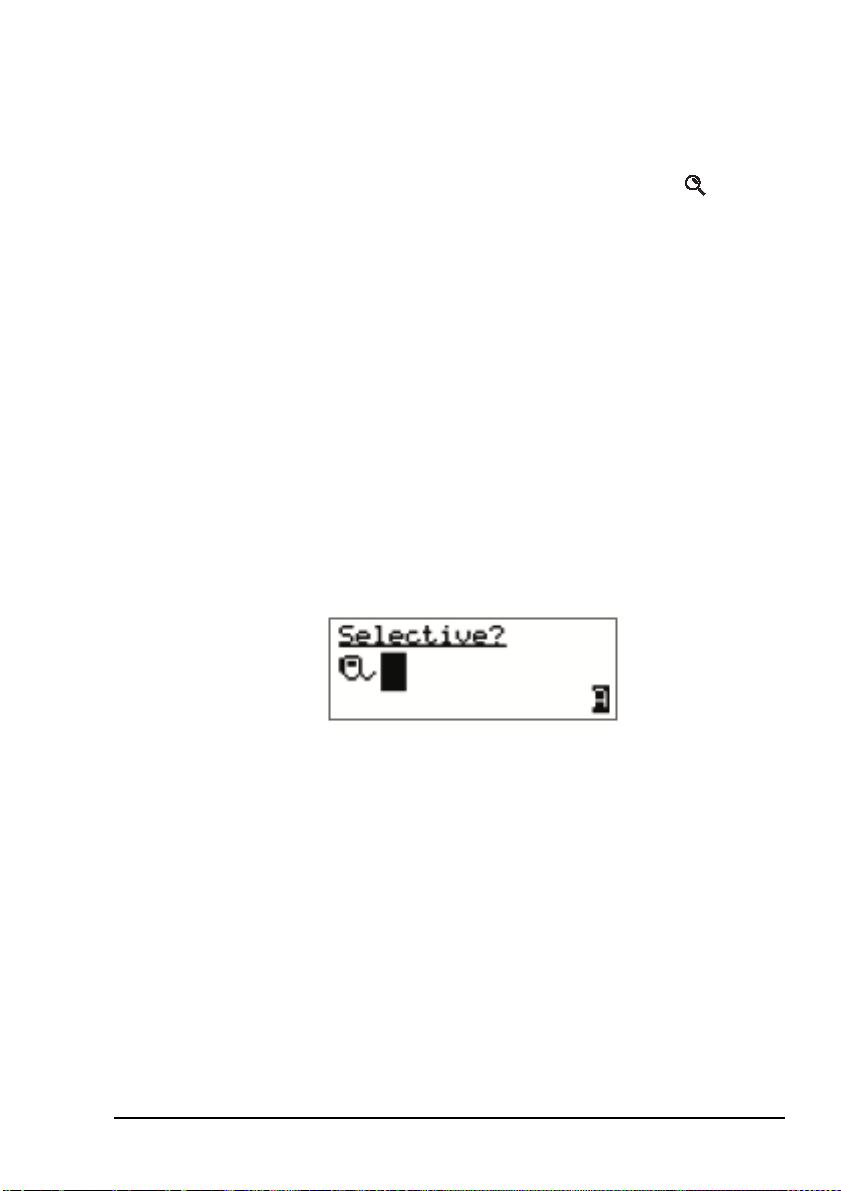
When you use a special ALE address syntax
through the Selective call type, the call icon will
change to the corresponding icon when the call
is started.
You may connect to:
NOTE
• one other station if there is a Selective icon
( ) on the channel screen
• a group of stations if there is an ANY icon
( ), Group Selective/NET icon ( ), or
Wildcard icon ( ) on the channel screen
• all stations scanning the channel if there is an
ALL icon ( ) on the channel screen
Your transceiver will inform you when the call has been
successful.
56 NGT ASR Transceiver Getting Started Guide
Page 65

Getting started
1 If required, hold down the PTT button then speak.
Release the PTT button when you have finished
speaking.
You are able to send data within the
NOTE
established link by pressing the key and
following the prompts.
1 To end the call, press the key.
The transceiver resumes scanning.
NGT ASR Transceiver Getting Started Guide 57
Page 66

Getting started
This page has been left blank intentionally.
58 NGT ASR Transceiver Getting Started Guide
Page 67

Appendix A—Standard hot keys
Q
Table 5: Standard hot keys on the handset
Key Hot key task
VIEW
0
Channel Screen: toggles between the Channel List and the Address
List.
TUNE
Manual Tune: displays the PTT to tune screen so you can manually
1
Z
tune the antenna.
CLAR
Clarifier: displays the Clarifier setting in the Control List so you can
2
ABC
change it, if necessary.
MODE
Next Mode: switches to the next possible mode for the currently
3
DEF
selected channel. To see the name of the mode, go to the Channel
List.
HELP
Help Mode: toggles Help Mode on or off.
5
JKL
SV
7
PRS
SEC
8
TUV
EASI
Easitalk: toggles Easitalk on or off.
*
CALL
Call Logs: displays the Calls Out Log, the Calls In Log, the Last
#
LOGS
Mute Type: toggles between Selcall mute and Voice mute.
Secure: toggles the VP-116 Voice Privacy Unit, if attached, or voice
encryptor on or off, if the hardware option is installed.
Heard Log, then returns to the screen from which you began.
CODAN
+ Screen Contrast: displays the Screen Contrast setting in the Control
9
WXY
List so you can change it, if necessary.
VIEW
0
+ Screen Brightness: displays the Screen Brightness setting in the
Control List so you can change it, if necessary.
NGT ASR Transceiver Getting Started Guide 59
Page 68

Standard hot keys
This page has been left blank intentionally.
60 NGT ASR Transceiver Getting Started Guide
Page 69

Appendix B—Entering and editing text
Editing a screen
To gain access to an editable screen:
1 Hold the key.
1 Do one of the following:
CODAN
A question mark is displayed at the end of the heading to
show that you can now enter and/or edit text in the
setting.
NOTE
• To use the text displayed, press the key.
If text has already been entered on the line
it is highlighted.
• To enter new text, start typing. When you have entered
the text, press the key.
• To edit the text displayed, press the key. The cursor
is placed at the end of the line so you can backspace
over characters and/or enter new text. When the text is
correct, press the key.
NGT ASR Transceiver Getting Started Guide 61
Page 70
Entering and editing text
Entering text
To enter text in an editable screen:
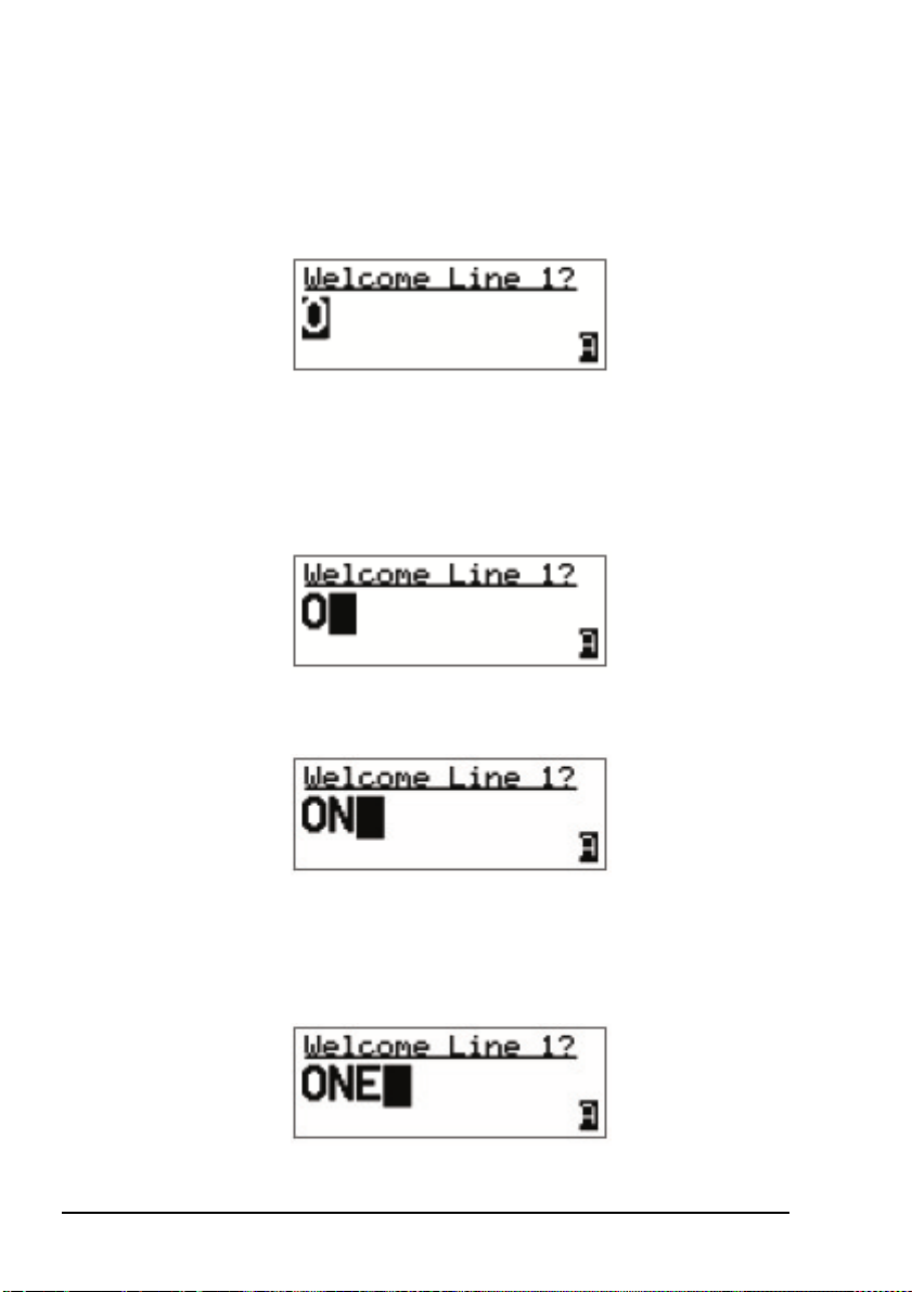
1 To enter one of the letters on a key, press the key
repeatedly until the letter is displayed.
NOTE
You can also hold the key until the letter
you want is displayed, then release the key.
1 To enter another letter on the same key, wait until the
cursor moves to the next space...
...then press the key repeatedly until the letter you want is
displayed.
1 To enter a letter on another key, press the key for the
letter.
You do not need to wait until the cursor moves to the
next space.
62 NGT ASR Transceiver Getting Started Guide
Page 71

Entering and editing text
L
S
Changing between alpha and numerical characters
To change between upper-case and lower-case letters and
numbers in an editable screen:
1 Press the key to change the character/case
indicator at the bottom right of the screen from ‘A’ to ‘a’
to ‘#’.
NOTE
CAL
#
LOG
When you are prompted to enter a call
address, the characters that you can enter
are determined by the call systems installed
in the transceiver.
Moving the cursor
To move the cursor across the text:
1 Use the and keys to move the cursor.
Inserting text
To ins ert tex t :
1 Use the and keys to move the cursor to the point
where you want to insert text (or a space), then press the
required character key.
If you want to insert a space, make sure
NOTE
that ‘A’ or ‘a’ is displayed at the bottom
right of the screen before you press the
VIEW
0
key otherwise you will enter a zero.
Deleting text
To delete text:
1 Use the and keys to move the cursor one position to
the right of the character that you want to delete, then
press the key.
NGT ASR Transceiver Getting Started Guide 63
Page 72

Entering and editing text
Entering special characters in messages and names
To enter special characters:
NOTE
The special characters that are available are:
. , ’ ? ! & # $ * ( ) - + /
1 Use the and keys to move the cursor to the point
where you want to insert a special character, then press
EASI
the key repeatedly until the symbol you want is
*
displayed.
Make sure that ‘A’ or ‘a’ is displayed at the
NOTE
To enter one of an extended range of special characters:
NOTE
bottom right of the screen before you press
EASI
the key otherwise you will enter a
*
decimal point.
The characters that are available are:
space , . ; ? : ¨ ‘ ’ / ! @ # $ % ^ &
* ( ) _ - + = | \ ~ < > { } [ ] 0 1 2 3 4
5 6 7 8 9
A B C D E F G H I J K L M N O P Q R S T
U V W X Y Z
a b c d e f g h i j k l m n o p q r s t u v w x
y z
1 Use the and keys to move the cursor to the character
or space where you want to replace a character.
NOTE
If you want to add a new character, enter a
space then move the cursor to this space.
1 Press the key to place an underscore beneath the
current character or space.
1 Use the and keys to scroll through the character
choices.
64 NGT ASR Transceiver Getting Started Guide
Page 73
Entering and editing text
S
1 When you have selected the character that you want to
use, use the or keys to scroll left or right
TUNE
1
QZ
3
respectively.
1 When you have made the changes, press the key to
exit the special character mode.
Entering text in an ALE call address
EASI
The key may be used to enter the special
NOTE
NOTE
To enter a special addressing character:
*
ALE addressing characters easily.
You can use any of the characters in the basic 38
ASCII subset (A–Z, 0–9, @ and ?) for the
address.
1 Ensure that you are in an editable address screen in
which you can enter upper-case letters (A).
MODE
DEF
1 Do one of the following:
*
*
*
EASI
EASI
EASI
#
CALL
LOG
• to enter an ‘@’ press the key once
• to enter a ‘?’ press the key twice while the cursor
is in the same space
• to enter a ‘,’ press the key three times while the
cursor is in the same space
• to enter any upper-case letter, press the corresponding
key
• to enter a number, press the key once to change
to numeric text entry, then press the corresponding key
NGT ASR Transceiver Getting Started Guide 65
Page 74

Entering and editing text
Saving text changes
To save the changes you have made:
1 Press the key.
The question mark is removed from the heading.
If you do not want to save the text, hold the key to
discard the changes.
66 NGT ASR Transceiver Getting Started Guide
Page 75

Appendix C—Finding words and values
CODAN
Finding a word
To find any word in the Main Menu or in the name of an entry:
1 From the Main Menu select the list in which you want to
search.
1 Press the key once.
The Find prompt is displayed on the top line.
1 Enter the first character of the word you want to find.
The first item that contains a word beginning with this
character is displayed.
If there aren’t any words that begin with this character
the character is deleted and an error beep is made.
To refine your search, enter more
NOTE
characters in the word you want to find.
To backspace over text, press the key.
1 Scroll through the list until the item you want is
displayed on the active line.
1 Press the key to exit Find at the entry.
NGT ASR Transceiver Getting Started Guide 67
Page 76

Finding words and values
Finding a value
To find a value that begins with a specific character:
1 From the Main Menu select the list in which the value is
stored.
NOTE
You cannot use this type of search in the
Main Menu or in the Control List.
1 Press the key twice.
The Find prompt is displayed on the top line with the
name of the first setting in the entry. For example:
The search for a value will be conducted in
NOTE
the setting displayed. To search for a value
in a different setting, press the key until
that setting is displayed.
1 Enter the first character of the value you want to find.
The first entry that contains a value beginning with this
character is displayed, and the value is displayed beneath
it.
If there aren’t any values that begin with this character
the character is deleted and an error beep is made.
To refine your search, enter more
NOTE
68 NGT ASR Transceiver Getting Started Guide
characters in the value you want to find.
To backspace over text, press the key.
Page 77

Finding words and values
1 Scroll through the entries until the one you want is
displayed.
1 Press the key to exit Find at the entry.
NGT ASR Transceiver Getting Started Guide 69
Page 78

Finding words and values
This page has been left blank intentionally.
70 NGT ASR Transceiver Getting Started Guide
Page 79

Appendix D—Creating an entry in a list
CODAN
NOTE
To create an entry in a list:
This process does not apply to entries in the
Control List.
1 Select the list in which you want to create an entry.
1 Hold the key to open the List Manager.
1 Select Create entry.
The transceiver suggests a name for the new entry based
on the name of the entry you were on.
1 Enter the name that you want to use for the new entry.
The name must be unique to the list that you are in.
NOTE
For help with entering text see page 61,
Entering and editing text.
1 Press the key.
The transceiver will prompt you to enter settings for the
entry.
For information on settings for your
NOTE
The new entry is created and the List Manager remains
open.
NGT ASR Transceiver Getting Started Guide 71
particular list see the reference material on
the enclosed CD.
Page 80

Creating an entry in a list
1 If you want to view the entry you have created, close the
List Manager by pressing the key.
1 Press the key repeatedly until you return to the Main
Menu.
72 NGT ASR Transceiver Getting Started Guide
Page 81

Appendix E—HF radio transmission
The HF band is the range of frequencies between 3 and
30 MHz. HF transceivers usually cover a frequency range of
1.6 to 30 MHz.
Codan HF transceivers transmit on single sidebands. This
reduces the power required to send HF signals and increases
the number of channels available within the HF spectrum.
HF transceivers are primarily used for long-range
communication where distances of 3000 km and more are
possible. Obstructions such as buildings and mountains have
little effect on long-range communication. HF radio can cover
such large distances because of the way the transmitted radio
signal propagates.
HF radio waves propagate in three ways simultaneously:
• ground wave
• direct wave
• sky wave
CODAN
Ground wave
The ground wave travels near the ground for short distances,
typically up to 100 km over land and 300 km over sea. The
distance covered depends upon the operating frequency,
transmission power and type of terrain.
Direct wave
The direct wave travels in a direct line-of-sight from the
transmitter to the receiver.
NGT ASR Transceiver Getting Started Guide 73
Page 82

HF radio transmission
Sky wave
The sky wave is the most important form of HF propagation.
The radio wave is transmitted toward the sky and is reflected
by the ionosphere to a distant receiver on earth.
The reflective properties of the ionosphere change throughout
the day, from season to season, and yearly.
Figure 7: The reflective properties of the ionosphere
ionosphere
emitted
HF wave
transmitter
Frequency, distance and time of day
The extent to which a radio wave is reflected depends on the
frequency that is used. If the frequency is too low the signal is
absorbed by the ionosphere. If the frequency is too high the
signal passes straight through the ionosphere. Within the HF
band, low frequencies are generally considered to be in the
range of 2 to 10 MHz. High frequencies are above 10 MHz.
A frequency chosen for daytime transmission may not
necessarily be suitable for night-time use. During the day the
layers of the ionosphere are thick. The layers absorb lower
frequencies and reflect higher frequencies. At night, the
ionosphere becomes very thin. The low frequencies that were
absorbed during the day are reflected and the high frequencies
that were reflected during the day pass straight through.
Summer HF communications usually operate on higher
frequencies than those used in winter over the same distance.
reflected
HF wave
receiver
74 NGT ASR Transceiver Getting Started Guide
Page 83

Solar activity varies over an 11 year cycle. Higher frequencies
need to be used during periods of peak activity.
It is important to remember that you may need to change the
frequency you are using to achieve the best communication.
The general rules of thumb for HF communication are:
• the higher the sun, the higher the frequency
• the further the distance, the higher the frequency
Channels and modes
A channel is a name that is given to a frequency or a pair of
frequencies, e.g. ‘Channel 1’, ‘4500’ and ‘Headquarters’. The
frequencies may be any frequencies within the HF range.
Each channel has one or more modes associated with it. Each
mode indicates a sideband that can be used with the channel,
such as USB or LSB. When you make a call you need to
specify the channel and the mode you want to use.
Tabl e 6 shows examples of channels and the information
associated with them.
HF radio transmission
Table 6: Examples of channels and modes
Channel Receive frequency
(kHz)
Transmit frequency
(kHz)
Modes
Channel 1 10 600 10600 LSB, USB
4500 4500 – AM
Headquarters 22 758 23000 USB
NGT ASR Transceiver Getting Started Guide 75
Page 84

HF radio transmission
Networks and scanning
A network is two or more stations that use the same
frequencies and call system to communicate.
The frequencies are allocated by a government authority and
enable the network to maintain HF communication throughout
the day and night.
The call system is the method the network uses to make and
receive calls. For example, in networks that use the
ALE/CALM call system, the transceiver selects the best
channel/mode for the call.
The transceiver can be set to scan the channel/modes used by
your network to detect incoming calls. It is recommended that
when you are not using the transceiver to communicate you
switch scanning on. This ensures that you can receive calls
from stations in your network.
The CALM option
The NGT ASR transceiver has the CALM option installed as
standard. CALM stands for Codan Automated Link
Management.
The CALM option enables the transceiver to test the signal
propagation qualities of your channels and build a profile of
each channel’s suitability for use at different times of the day
and night. The transceiver can then select the most suitable
channel/mode for you when you make a call. You are able to
make ALE ALL calls with this option.
CALM is compatible with FED-STD-1045 ALE.
76 NGT ASR Transceiver Getting Started Guide
Page 85

The Advanced ALE options
The Advanced ALE options are installed in addition to the
CALM option, and are standard for the NGT ASR transceiver.
They provide the capability to make ALE calls using ALL,
ANY, Group Selective, NET and Wildcard address syntaxes.
These calls are from one station to many stations at the same
time. The Advanced ALE options also provide advanced link
quality analysis and advanced messaging.
The Advanced ALE options are interoperable with
FED-STD-1045 ALE and MIL-STD-188-141B.
Etiquette for the use of HF radio
There is a standard procedure for communicating over HF
radio. Before you begin transmitting, switch off scanning,
select a channel, then press the PTT button to initiate tuning of
the antenna. Listen to the channel that you are going to use and
ensure that there is no voice or data communication taking
place. You may need to wait until the channel is clear or select
another channel.
HF radio transmission
If you have the Cfg LBT Mode set to Enabled or
NOTE
Override allowed, the transceiver searches for a
channel that is not being used; you do not need
to check any channels first.
When you first establish communication with another station
it is customary to state their call sign and then your own using
the phonetic alphabet (see Table 7 on page 78). For example:
‘Alpha Bravo One, this is Alpha Bravo Two. Do you receive
me? Over.’
In this example your call sign is AB2 and you are calling a
station with the call sign AB1. A call sign is a group of letters
and numbers issued by a government authority to identify a
station. The phonetic alphabet is used to ensure that your call
sign is understood.
NGT ASR Transceiver Getting Started Guide 77
Page 86

HF radio transmission
The word ‘over’ is used to signify the end of your
transmission. The transceiver may be set up to transmit a short
beep when you release the PTT button on the handset. When
your conversation with the other party is finished, the party
that speaks last should say ‘out’.
Swearing or foul language should not be used—heavy
penalties can apply.
Keep communication as short as possible.
Table 7: The phonetic alphabet
Letter Word Letter Word
A Alpha N November
B Bravo O Oscar
CCharliePPapa
D Delta Q Quebec
EEchoRRomeo
F Foxtrot S Sierra
G Golf T Tango
HHotelUUniform
I India V Victor
J Juliet W Whiskey
K Kilo X X-ray
LLimaYYankee
M Mike Z Zulu
78 NGT ASR Transceiver Getting Started Guide
Page 87

Appendix F—Definitions
Standards and icons
The following standards and icons are used in this guide:
This typeface Means...
Italic a cross-reference or text requiring emphasis
This icon Means...
! a step within a task
CODAN
NOTE
CAUTION
WARNING
the text provided next to this icon may be of
interest to you
proceed with caution as your actions may
lead to loss of data, privacy or signal quality
your actions may cause harm to yourself or
the equipment
NGT ASR Transceiver Getting Started Guide 79
Page 88

Definitions
Acronyms and abbreviations
This term Means...
ALE automatic link establishment
AM amplitude modulation
CALM Codan automated link management
DC direct current
HF high frequency
ID identification
LBT listen before transmit
LCD liquid crystal display
LED light emitting diode
LSB lower sideband
LQA link quality analysis
NSP NGT system programmer
PA power amplifier
PC personal computer
PTT press-to-talk
RF radio frequency
Rx receive
SB sideband
tcvr transceiver
Tx transmit
USB upper sideband
V firmware/software version
80 NGT ASR Transceiver Getting Started Guide
Page 89

Glossary
Definitions
This term Means...
active line The line below the title of a list on the
handset screen. Items in the active line are
selected by pressing the key.
address The HF transceiver equivalent of a
telephone number. Your station self address
is used by other stations to call you, and it is
sent when you make calls to identify you as
the caller. It is sometimes referred to as an
ID, a station ID, or a self ID.
ALL call An ALE address syntax used to broadcast to
any station that is tuned to the same
frequency in an ALE/CALM network or
scanning the network. The ALL call uses a
special address syntax @?@ that ALE
stations recognise. The ALL call does not
request any automatic responses from
stations that enter the link. Stations can be
configured to enter a link on detecting an
ALL call or to ignore an ALL call.
A selective ALL call addresses a subset of
stations tuned to the same frequency in an
ALE/CALM network or scanning the
network.
A multiple selective ALL call addresses
these subsets within the one call.
NGT ASR Transceiver Getting Started Guide 81
Page 90

Definitions
This term Means...
ANY call An ALE address syntax used to broadcast to
any station that is tuned to the same
frequency in an ALE/CALM network or
scanning the network. The ANY call uses a
special address syntax @@? that ALE
stations recognise. The ANY call requests
an automatic response from stations
detecting the call. These responses are
returned in any slot position (collisions may
occur). The initiating station then completes
the link establishment with an
acknowledgement sent to all stations from
which it received a response. The operator
at the initiating station can use these
responses to gather information on the
status of the stations using the network.
Stations can be configured to respond to or
to ignore ANY calls.
A selective ANY call addresses a subset of
stations tuned to the same frequency in an
ALE/CALM network or scanning the
network.
A multiple selective ANY call addresses
these subsets within the one call.
automatic tuning
antenna
An antenna designed for use with
multichannel transceivers. It uses a
microcontrolled stepper motor to give
continuous tuning over the operating
frequency range of the antenna.
channel Frequencies programmed in the transceiver
to transmit and receive signals on air.
82 NGT ASR Transceiver Getting Started Guide
Page 91

This term Means...
Definitions
Channel Test
call
A call that enables you to test the quality of
a channel. It is sometimes referred to as a
Beacon call. Channel Test calls may be
made in an ALE/CALM network to replace
information in the LQA database, and to
perform a manual sounding operation.
control cable A cable connecting two items of equipment
that allows control information to be passed
between the equipment.
Emergency call A call that enables you to trigger an
emergency alarm at a specific station then
speak to an operator there.
fixed base
station
A transceiver that is permanently installed
and cannot be moved without significant
effort. It consists of a transceiver, a
transceiver supply, an antenna, control and
accessory devices, ancillary equipment, and
appropriate connecting cables.
frequency The number of cycles per second of a radio
wave, usually expressed in kilohertz.
Get Position call A call that gets the GPS position of a
specific station.
Get Status call A call that gets diagnostic information
about the transceiver at a specific station.
NGT ASR Transceiver Getting Started Guide 83
Page 92

Definitions
This term Means...
Group Selective
call
An ALE call that is sent to stations
specifically addressed in the call that are
tuned to the same frequency in an
ALE/CALM network or scanning the
network. The Group Selective call requests
an automatic response from stations that
detect the call. These responses are returned
in reverse order from that provided in the
call. The initiating station then completes
the link establishment by sending an
acknowledgement to all stations from which
it received a response.
handset A hand-held device that is used to control
the functions of a transceiver. It consists of a
microphone, PTT button, display and
keypad.
hot key A key on the handset or desk console that is
pre-programmed with a macro that enables
you to perform a task quickly.
junction box The unit in a transceiver to which a handset,
RF unit, speaker and related devices are
connected. The junction box receives the
instructions that a user enters through the
handset and sends these instructions to the
relevant devices.
Last Heard Log A log of the last 100 on-air transmissions
detected by the current station. The
information gathered from each
transmission includes the self address of the
heard station, the time/date of the
transmission, and the channel/mode used
for the transmission.
84 NGT ASR Transceiver Getting Started Guide
Page 93

Definitions
This term Means...
link A link is established following a 3-way
handshake process. Scanning is off and a
timeout, set using the Cfg In Call Timeout
entry in the Control List, will be active.
With ALL calls and NET calls that are set to
link immediately, the linking establishment
process is 1-way.
listen before
transmit
If enabled, the automatic process that the
transceiver uses to detect whether or not
there is traffic on a channel and, when
necessary, select another channel or inform
the user that the channel is busy.
LQA beacon A Channel Test call made in an
ALE/CALM network using a Group
Selective or NET address syntax. The LQA
beacon tests all channels within the network
to determine the best channel according to
local and remote BER and SINAD
measurements. On completion of the
beacon, the information collected replaces
the information for the channel stored in the
LQA database. It is sometimes referred to as
an ALE beacon.
macro A short set of instructions to automate a task
you perform with the transceiver. When a
macro is assigned to a key, the key becomes
a hot key.
manual sounding A Channel Test call made in an
ALE/CALM network using the text
SOUNDING as the call address. The station
performs a sounding operation, which other
stations use to update the information in
their LQA database.
Message call A call that enables you to send a message to
a specific station.
NGT ASR Transceiver Getting Started Guide 85
Page 94

Definitions
This term Means...
mobile station A station that is usually mounted in a
vehicle or is portable and easily
transportable. It consists of a transceiver, a
power supply, an antenna, control and
accessory devices, ancillary equipment, and
appropriate connecting cables.
mode A type of reception or transmission you can
use with a channel e.g. USB.
NET call An ALE address syntax that is used to send
a call from one station to other stations that
have the NET programmed in the NET List.
If these stations have their self address in
the Member Address setting they become
members of this NET. The member stations
send an automatic response to the initiating
station in a pre-determined response slot, if
enabled to do so. The initiating station then
completes the link establishment with all
member stations. Any other stations with
the NET programmed will enter the link at
this time too.
network Two or more stations that use the same
frequencies and call system to
communicate.
Phone call A call that enables you to connect to a
public telephone network.
PTT button Press-to-talk button, located on the left side
of the handset. This button enables you to
communicate during voice calls, switch
mute off, cancel voice calls prior to the
point where voice can be transmitted, cancel
calls where data is being transmitted, and
exit out of editable screens without saving
changes.
86 NGT ASR Transceiver Getting Started Guide
Page 95

Definitions
This term Means...
revertive A signal sent by a station in response to a
call.
RF unit The unit in a transceiver that modulates
audio signals onto radio frequencies that
can be transmitted on air, and that
demodulates the radio frequencies it
receives into audio signals.
Selective call A call that enables you to contact a specific
station then speak to an operator.
Send Position
call
A call that sends your GPS position to a
specific station.
station A point of communication consisting of a
transceiver, a power supply, an antenna,
ancillary equipment, and appropriate
connecting cables.
transceiver An RF unit, junction box, handset, speaker,
and appropriate connecting cables.
Wildcard call An ALE address syntax used to broadcast to
any station that is tuned to the same
frequency in an ALE/CALM network or
scanning the network. The Wildcard address
syntax, which ALE stations recognise, uses
the wildcard character ? as a placeholder for
characters within a self address of a
receiving station. Stations that detect the
call and whose self address matches the
pattern in the wildcard address will send a
response to the initiating station. These
responses are returned in any slot position
(collisions may occur). The initiating station
then completes the link establishment with
an acknowledgement sent to all stations
from which it received a response.
A multiple Wildcard call addresses
matching subsets within the one call.
NGT ASR Transceiver Getting Started Guide 87
Page 96

Definitions
Units
Measurement Unit Abbreviation
Distance metre m
Frequency hertz Hz
Time second s
Voltage volt V
Unit multipliers
NOTE
Units are expressed in accordance with ISO
1000:1992 ‘SI units and recommendations for
the use of their multiples and of certain other
units’.
Unit Name Multiplier
Mmega1000000
kkilo1000
m milli 0.001
88 NGT ASR Transceiver Getting Started Guide
Page 97

About this issue
This is the first issue of the NGT ASR Transceiver Getting
Started Guide.
Associated documents
This guide is one of a series of documents associated with the
NGT transceiver. The other documents are:
•NGT ASR Transceiver Reference Manual (Codan part
number 15-04138-EN) supplied on the CD inside the
back cover of this guide
• NGT Transceiver System Technical Service Manual
(Codan part number 15-02063-EN)
• Declaration of Conformity for the NGT ASR transceiver
(Codan part number 19-40131)
• Declaration of Conformity for the 3020 Transceiver
Supply (Codan part number 19-40127)
Definitions
NGT ASR Transceiver Getting Started Guide 89
Page 98

Definitions
This page has been left blank intentionally.
90 NGT ASR Transceiver Getting Started Guide
Page 99

Index
CODAN
A
Address List
calling from 49, 51
Advanced ALE options 77
B
best channel
selecting 48
brightness
screen 34
C
cables
fixed station 19
mobile station 14
call sign 77
call systems
ALE/CALM 76
call types
Emergency 43, 53
calls
from Address List 49, 51
using emergency key 43, 53
using special ALE address syntaxes 55
CALM option 76
channel screen 28
channels
automatic selection 76
definition 75
manual selection 30
compliance
electromagnetic compatibility and safety
notices 7
earth symbols 8
electrical safety 8
electromagnetic compatibility 7
protection of the radio spectrum 6
European Radio and Telecommunications
Terminal Equipment Directive 5
FCC 10
contrast
screen 33
creating an entry in a list 71
D
direct wave 73
E
electromagnetic compatibility and safety notices
compliance
earth symbols 8
electrical safety 8
electromagnetic compatibility 7
protection of the radio spectrum 6
Emergency calls 43, 53
emergency key 43, 53
entering and editing text
changing between alpha and numerical
characters 63
deleting text 63
editing a screen 61
entering special characters in messages and
names 64
entering text 62
entering text in a call address 65
inserting text 63
moving the cursor 63
saving text changes 66
European Radio and Telecommunications
Terminal Equipment Directive
compliance 5
F
FCC compliance 10
FED-STD-1045 ALE 76
finding
a value 68
a word 67
fixed station 18
cables 19
installing 21
mounting 19
NGT ASR Transceiver Getting Started Guide Index-1
Page 100

Index
19 inch rack-mounting unit 20
desk console 19
mounting cradles 20
frequency selection
depending on distance and time of day 74
G
ground wave 73
H
handset keys 23, 35
HF radio transmission 73
hot keys
standard 59
I
installation 11
fixed 18
mobile 12
L
LBT Mode 42
list
creating an entry 71
LQA information
replacing using Channel Test call 44
M
Main Menu
accessing 37
manual sounding 47
MIL-STD-188-141B 77
mobile station 12
cables 14
installing 16
mounting 14
handset cradle 14
junction box 15
RF unit 15
speaker 15
modes 30, 75
muting the transceiver 39
setting the mute type 39
N
networks 76
NGT fixed station 18
NGT mobile station 12
O
Option
Advanced ALE 77
P
password
entering 32
phonetic alphabet 78
power on/off 32
S
safety
radiation 7
scanning channels 38, 76
pausing channel scanning 38
screen
brightness 34
contrast 33
selecting
an item in a list 36
channel 30
selecting the best channel 48
sky wave 74
sounding
manual 47
standard hot keys 59
station
fixed 18
installing 21
mounting 19
mobile 12
installing 16
mounting 14
station self address
entering 40
Index-2 NGT ASR Transceiver Getting Started Guide
 Loading...