

Page 1

TECHNICAL NOTES
Technical Notes for
Tuning, Installing,
Maintaining and Servicing
MT-3 and MT-4 Radio Systems
Codan Communications
43 Erie Street
Victoria, British Columbia
Canada V8V 1P8
International
Phone: 250-382-8268
Fax: 250-382-6139
Email: LMRsales@codancomms.com
Web: www.codancomms.com
Toll Free Canada and U.S.A.
Phone: 1-800-664-4066
Fax: 1-877-750-0004
Page 2

Table of Contents
System Overview
TN105 Dual Subrack Interconnection
TN110 Channel and Frequency Selection
TN150 Repeater / Tone Remote Controlled Base Station
TN151 Base Station Interface Connections
TN152 Linked Repeater Networks
TN160 Base Station or Link Confi guration Settings
TN175 MT-4E Firmware Upgrading
TN180 P25 Digital Ping Feature
TN181 Adjustable Courtesy Tone
TECHNICAL NOTES
MT-3/4 Radio Systems
TN182 Battery Level Reporting and Remote P25 Test Tone
Receiver Modules
TN247 VR-4E VHF MT-4E Receiver
TN267 UR-4E UHF MT-4E Receiver
TN287 UR-4E UHF 700 / 800 / 900 MHz MT-4E Receiver
Transmitter Modules
TN347 VT-4E VHF MT-4E Transmitter
TN367 UT-4E UHF MT-4E Transmitter
TN387 UT-4E UHF 700 / 800 / 900 MHz MT-4E Transmitter
Power Amplifi ers
TN441 AMP-4 VHF and UHF 30 Watt Power Amplifi ers
TN490 19” Rack Mount High Power Amplifi ers
TN491 Modular 5-Pack Series High Power Amplifi ers
TABLE OF CONTENTS
CANADA/US +1 250 382 8268 | TOLL FREE +1 800 664 4066
CODANCOMMS.COMTECHNICAL NOTE:
LMRSALES@CODANCOMMS.COM
Page 3

Table of Contents
Subracks
TN500 SR-39-1 Subrack
TN520 SR-39-3 Multiple Receiver Subrack
Control Cards
TN600 AC-3E Audio Control Card
TN640 CI-PM-3 Paging Modulator
TN650 CI-RC-4L Repeater Control Card
TN652 CI-RC-4M-G2 Multiple Link Controller
TN655 CI-BC-4E Base Control Card
TECHNICAL NOTES
MT-3/4 Radio Systems
TN661 UIC-5 Universal Interface Card
TN670 Stratus Controller
Transportable Systems
TN710 ET-3 Transportable Radio System Case
TN720 ET-4 Transportable Radio System Case
TN730 ET-5 Transportable Tactical Radio System
TN735 ET-6 Transportable Tactical Radio System
TN750 ET-1 Transportable Radio System Case
TN760 Stratus Transportable Tactical Radio System
TN761 Stratus Fixed Infrastructure Radio System
TN765 Stratus Tactical Controller
TN790 Transportable Radio System Accessories
TN791 Stratus Power Center
TN792 Stratus Rapid Antenna
TABLE OF CONTENTS
CANADA/US +1 250 382 8268 | TOLL FREE +1 800 664 4066
CODANCOMMS.COMTECHNICAL NOTE:
LMRSALES@CODANCOMMS.COM
Page 4

MT-3/4 Radio Systems
Table of Contents
Other
TN800 A-PNL-AUX96-3 Auxiliary Connector
TN811 SM-3 System Regulator
TN830 AC to DC and DC to DC Power Supplies
TN835 High Current AC to DC Power Supplies
TN836 High Current Digital Series AC to DC Power Supplies
TN840 Extender Cards and Kits
TN855 CI-DSP-223 Telex (Vega) DSP Tone-Remote Adapter
TN856 CI-IP-223 Telex (Vega) IP Network Remote Adapter
TN857 CI-IP-ADAPTER-1 Telex (Vega) IP-224 Ethernet Adapter
TECHNICAL NOTES
TN870 CI-RSWITCH Redundant Switch
TABLE OF CONTENTS
CANADA/US +1 250 382 8268 | TOLL FREE +1 800 664 4066
CODANCOMMS.COMTECHNICAL NOTE:
LMRSALES@CODANCOMMS.COM
Page 5

TECHNICAL NOTES
MT-3/4 Radio Systems
TN105 Dual Subrack Interconnection
The SR-39-1 subrack is designed to hold and interconnect the MT-3 and MT-4 series of receiver, transmitter and
control modules on one universal motherboard. This motherboard distributes audio, control and power signals
between the separate modules plugged into the subrack. The two main power signals used by the MT-3 and MT-4
modules are the +13.8 Vdc (power input) and +9.5 Vdc (regulated) power.
The +13.8 Vdc power input (+13.8 Vdc nominal, +10 to +17 Vdc range) is connected to the motherboard by a
terminal strip mounted on the back of the subrack. The +13.8 Vdc signal line is routed through the System Regulator
(SM-3) module and then distributed across the motherboard to the other modules. This allows the user to un-plug
the SM-3 module and turn off all power supplied to the other modules. This feature is not used very often as all
Codan modules are capable of being hot swapped.
The +9.5 Vdc regulated power is generated in the System Regulator module by the internal +9.5 Vdc voltage
regulator built into the SM-3. This +9.5 Vdc regulated voltage is then distributed across the motherboard to the
other modules. The voltage regulator is designed to source enough current to operate all modules in the subrack.
If a Codan radio system is designed so that a second subrack is required, the confi guration is dependent on the
modules in the second subrack:
Receivers, Transmitters or Control Cards In Second Subrack
If the second subrack requires receiver, transmitter or control cards, a system regulator is required in the second
subrack to source enough current for the +9.5 Vdc regulated voltage to these modules.
AMP-4 30 Watt Power Amplifi ers
If the second subrack contains Codan AMP-4 series 30 Watt power amplifi er modules, the AMP-4 series amplifi ers
do NOT use +9.5 Vdc power, so ONLY the +13.8 Vdc connection is required on the second subrack.
AMP-2 30 Watt Power Amplifi ers
If the second subrack contains Codan AMP-2 series 30 Watt power amplifi er modules (see Figure 1), the +9.5 Vdc
power is required, however, the regulated voltage current draw for these modules is very low, and the SM-3 in the
fi rst subrack can source enough current for the power amplifi ers in the second subrack. In this case, a second SM-3
module is not required, and the +9.5 Vdc regulated voltage is jumpered from the fi rst subrack with the SM-3 to the
second subrack with no SM-3 module, using the +9.5 Vdc input / output connector on the motherboards.
Jumper JU1 required on all second subracks with no SM-3 (AMP-2 and AMP-4 series)
If the second subrack has no SM-3 module installed, jumper JU1 is required to be installed in the second subrack
to allow +13.8 Vdc power to be connected to the 30 Watt power amplifi ers (the +13.8 Vdc is typically routed through
the SM-3). Jumper JU1 is typically a 16 AWG wire soldered across the jumper points (see Figure 2 for jumper wires
and JU1 placement). On older motherboards (Serial # 123125 and earlier) the jumper is in the same location, but
is labelled as JU40.
If a radio system is ordered from the factory with these confi gurations, the jumper wires are included in the shipment
and jumper JU1 is installed at the factory.
TECHNICAL NOTE: TN105, REV 6-0-0, © November 2018
CANADA/US
+1 250 382 8268 | TOLL FREE +1 800 664 4066
CODANCOMMS.COM
LMRSALES@CODANCOMMS.COM
Page 1 of 2
Page 6
TN105 Dual Subrack Interconnection
FIRST SUBRACK WITH
TRANSMITTERS, RECEIVERS,
SYSTEM MONITOR & CONTROL CARD
CI-RC-4L
REPEATER
CONTROL
PULL DOWN
TO REMOVE
TRANSMITTER
FREQUENCY (MHz)
AD
REF
IN
NORM
OFF
KEYTX
ANALOG
MICMODE
CNTL
BUS
USB
MIC RF OUT
MADE IN CANADA
MODEL # CODE
DANIELS
ELECTRONICS LTD.
DIGITAL
TXA
RXA
TX B
RX B
RECEIVER
FREQUENCY (MHz)
AD
SQ. DISABLE
NORM
OFF
REF
IN
USB
RF NI
CNTL
BUS
DANIELS
ELECTRONICS LTD.
MADE IN CANADA
MODEL # CODE
MICMODE
CNTL
BUS
REF
IN
USB
TRANSMITTER
FREQUENCY (MHz)
AD
MIC RF OUT
DANIELS
ELECTRONICS LTD.
MADE IN CANADA
MODEL # CODE
NORM
OFF
KEYTX
ANALOG
DIGITAL
TECHNICAL NOTES
MT-3/4 Radio Systems
RECEIVER
FREQUENCY (MHz)
AD
SQ. DISABLE
NORM
OFF
REF
IN
USB
CNTL
BUS
DANIELS
ELECTRONICS LTD.
MADE IN CANADA
MODEL # CODE
SYSTEM REGULATOR
FUNCTION
1
12
2
11
3
10
4
9
5
8
67
POWER
+
METER
-
MADE IN CANADA
ON
OFF
VOL
ON
OFF
RF NI
SPKR
INT
EXT
EXT
SPKR
NO CONTROL CARD
REQUIRED
RF OUT
RF IN
POWERAMPLIFIER
PWR
TX
O / T
VSWR
FREQUENCY (MHz)
ON
OFF
DANIELS
ELECTRONICS LTD.
MADE IN CANADA
MODEL # CODE
SECOND SUBRACK WITH
AMP-2 SERIES 30 WATT
POWER AMPLIFIER MODULES
RF OUT
RF IN
POWERAMPLIFIER
PWR
TX
O / T
VSWR
FREQUENCY (MHz)
ON
OFF
DANIELS
ELECTRONICS LTD.
MADE IN CANADA
MODEL # CODE
NO SYSTEM MONITOR
REQUIRED
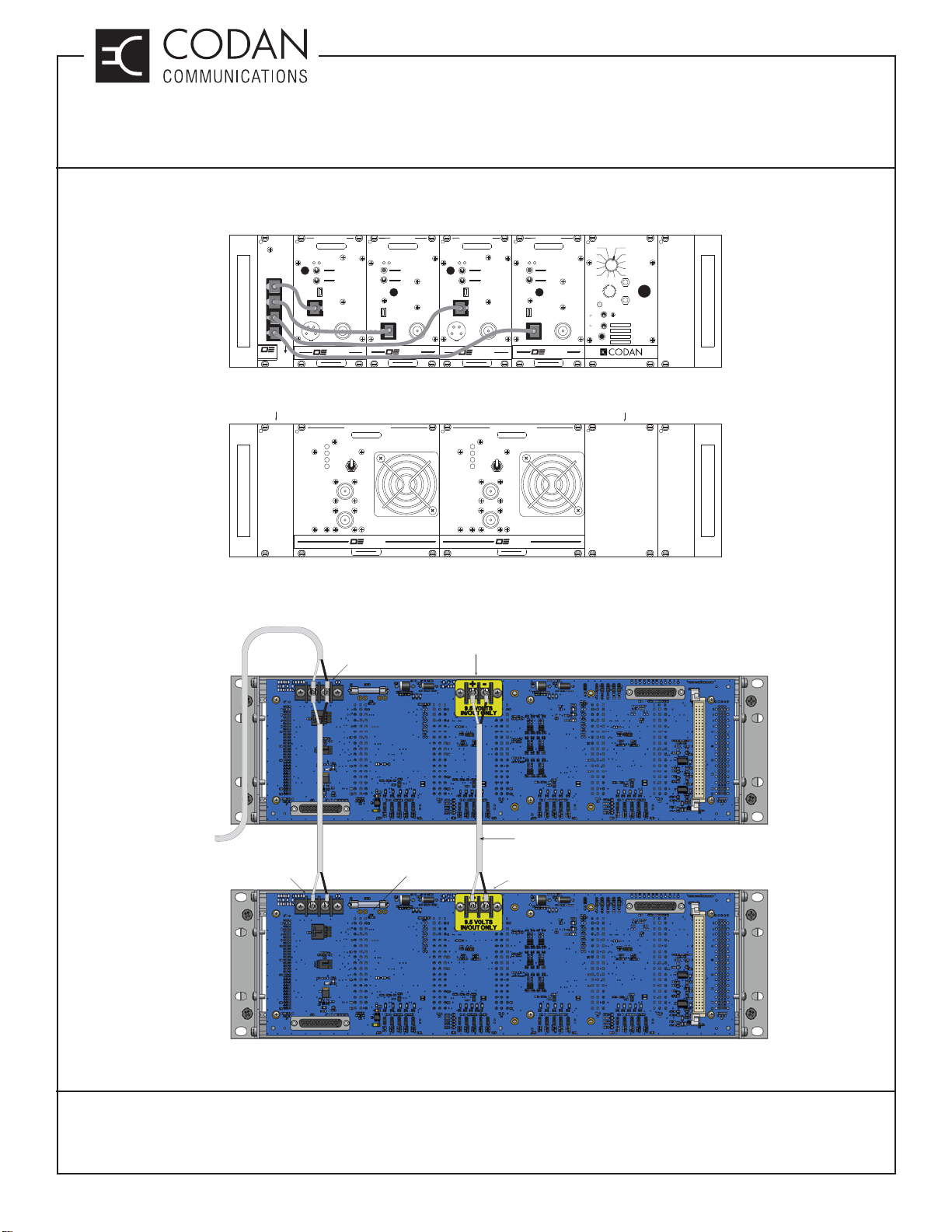
Figure 1 - Front View of Dual Subracks; Second Subrack has only AMP-2 series Power Amplifi ers
+9.5 Vdc
REGULATED
POWER OUTPUT
FIRST SUBRACK WITH
TRANSMITTERS, RECEIVERS,
SYSTEM REGULATOR & CONTROL CARD
+9.5 Vdc INTERCONNECT CABLE
REQUIRED FOR AMP-2 CONFIGURATIONS
(NOT AMP-4)
+9.5 Vdc
POWER INPUT
SECOND SUBRACK WITH
30 WATT POWER AMPLIFIER
MODULES ONLY
POWER
SUPPLY
INPUT
POWER INPUT
+10 to +17 Vdc
+13.8 Vdc NOMINAL
POWER INPUT
+10 to +17 Vdc
+13.8 Vdc NOMINAL
JU1 INSTALLED
WITH 16 AWG WIRE
(REQUIRED WHEN NO
SM-3 IS INSTALLED)
Figure 2 - Rear View of Dual Subracks; Jumper wires between fi rst and second subrack
CANADA/US +1 250 382 8268 | TOLL FREE +1 800 664 4066
Page 2 of 2
CODANCOMMS.COMTECHNICAL NOTE: TN105, REV 6-0-0, © Nov 2018
LMRSALES@CODANCOMMS.COM
Page 7
TECHNICAL NOTES
MT-3/4 Radio Systems
TN110 Channel and Frequency Selection
MT-4E Channel and Bank Selection
MT-4E radio modules are capable of 16 channel operation in 2 banks (32 channels total).
The 16 channels are controlled via four CSEL signal lines connected to each receiver and transmitter module. The
CSEL signal lines are set as either a 0 (0 Vdc) or a 1 (+9.5 Vdc). Table 1 shows the channel selected for the CSEL
input settings.
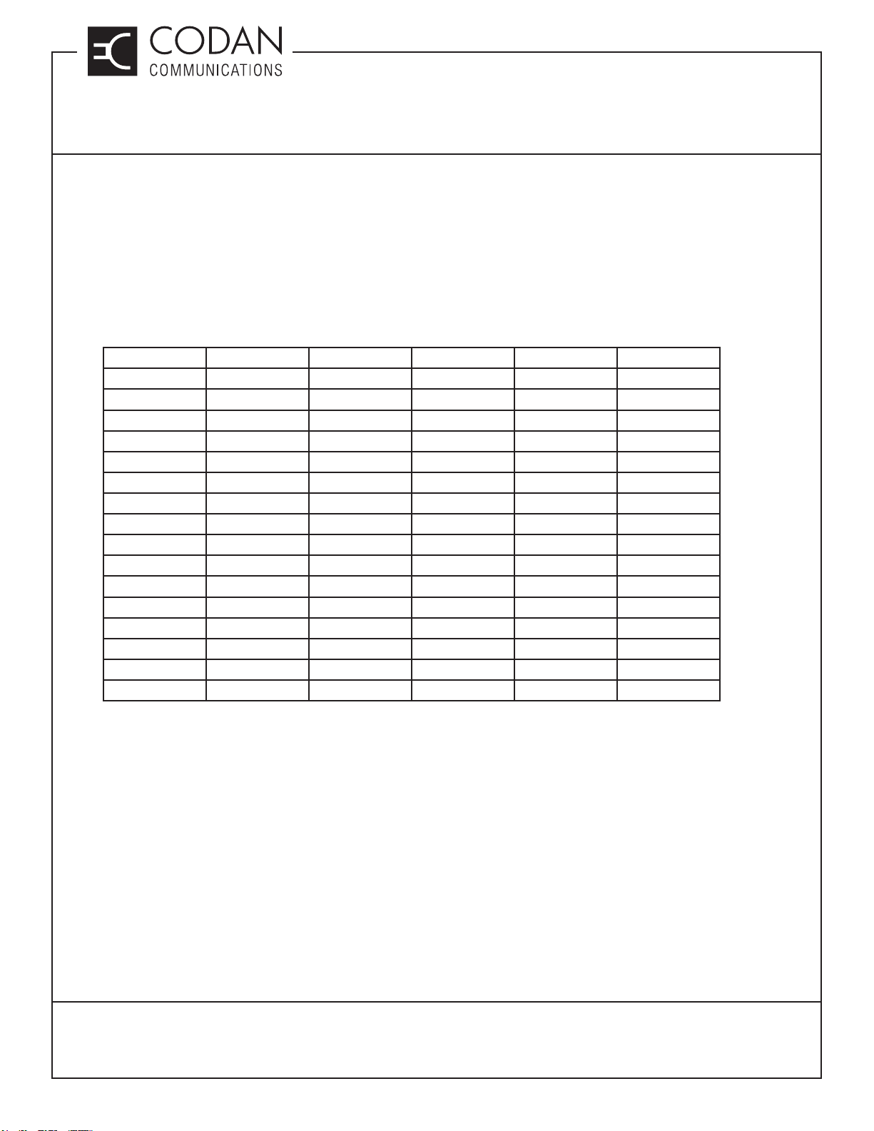
Table 1: Channel Selection Settings
Channel Decimal CSEL3 CSEL2 CSEL1 CSEL0
100000
210001
320010
430011
540100
650101
760110
870111
981000
1091001
11101010
12111011
13121100
14131101
15141110
16151111
The Receiver and Transmitter Bank A/B select lines are set as either a B (0 Vdc) or an A (+9.5 Vdc). The logic for
the Bank A/B select lines is diff erent from the CSEL signal lines. If the Bank A/B select line is pulled high (+9.5 Vdc),
or left fl oating, Bank A is selected. If the Bank A/B select line is pulled low (0 Vdc), Bank B is selected.
On older motherboards (Serial # 123125 and earlier), the Receiver Bank A/B select line uses the same line as the
MT-3 Receiver ISO COR K and the Transmitter Bank A/B select line uses the same line as the MT-3 Transmitter
Standby. No jumpers are available for the Bank select.
TN110, REV 4-0-0, © Aug 2016
CANADA/US +1 250 382 8268 | TOLL FREE +1 800 664 4066
LMRSALES@CODANCOMMS.COM
CODANCOMMS.COMTECHNICAL NOTE:
Page 1 of 4
Page 8

TECHNICAL NOTES
MT-3/4 Radio Systems
TN110 Channel and Frequency Selection
There are 3 diff erent ways to change the channel and bank of a transmitter / receiver module:
1 The user can set jumpers mounted on the motherboard for each Channel Select signal line (set of four for
each Tx / Rx module) and Bank A/B select line. These jumpers can be used to permanently set a subrack
slot at a specifi c channel and bank.
• Jumpers can be set for 0 (0 Vdc) “down” or 1 (+9.5 Vdc) “up”.
• Pull-up resistor jumpers to +9.5 Vdc must be installed.
2 CSEL signal lines and Bank A/B select lines can be controlled externally by a tone remote adapter, a
CI-RC-4M-G2 multiple link controller, or other third party devices.
3 Sixteen-position rotary select switches mounted on the CI-BC-4E base controller can control the CSEL lines
and toggle switches can control the Bank A/B select line. Optionally the CI-RC-4L repeater controller or AC-3E
control card can have a rotary switch added for control of the CSEL signal lines. The control lines can also be
controlled by selecting the channel through a UIC control card.
The Pull-up resistor jumpers to +9.5 Vdc must be removed and all channel select and bank select jumpers must be
installed in the 1 or “up” position for both external control and rotary switch control of channel selection.
MT-4 Modules Frequency Selection
The MT-4 modules operating frequency is selected in standard channel increments through the Radio Service
Software (RSS). Frequencies can be directly entered or selected through the use of a spin button that cycles
through valid frequencies.
Transmitter A Channel Select Switching Control Option
The motherboard can be jumper confi gured to allow switching control of the TXA CSEL lines between a control card
and an external connection such as a tone remote.
Jumpers JU86 to JU93 are installed by default to allow either the A-PNL-AUX96-3 auxiliary connector, or AC-3E /
CI-BC-4E / UIC-4 control cards to have control of the Transmitter A channel select lines. This will cause contention
if both a control card and auxiliary connection attempt to change the channel select lines.
Switching control of the Channel Select lines can be selected by use of two General Purpose Inputs. GPIO22 and
GPIO23 allow for the use of a connection to Ground to enable or disable local control.
GPIO22 - Ground disables local (AC-3E / CI-BC-4E / UIC-4) control & enables auxiliary control.
GPIO23 - Ground enables local (AC-3E / CI-BC-4E / UIC-4) control & disables auxiliary control.
To allow switching control of the channel select lines remotely, remove jumpers JU86 to JU93, and install jumpers
JU94 to JU101, then install jumper JU102 or JU103 to determine if an active low will enable or disable the local
control of the channel select control.
TN110, REV 4-0-0, © Aug 2016
CANADA/US +1 250 382 8268 | TOLL FREE +1 800 664 4066
Page 2 of 4
LMRSALES@CODANCOMMS.COM
CODANCOMMS.COMTECHNICAL NOTE:
Page 9
TECHNICAL NOTES
MT-3/4 Radio Systems
TN110 Channel and Frequency Selection
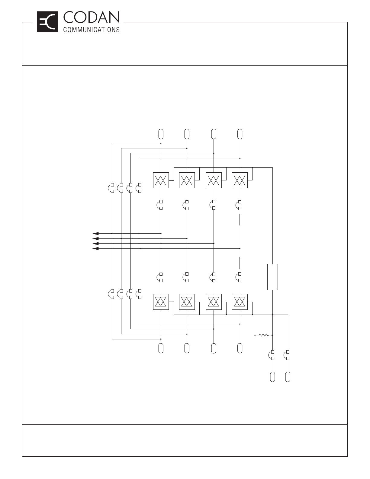
Transmitter A Channel Select Switching Control Option Diagram
(J1)
UIC-4
AC-3E
CI-BC-4E
CONNECTOR
TXA CSEL3
TXA CSEL2
TXA CSEL1
TXA CSEL0
JU87
JU86
JU89
JU88
JU91
JU90
JU93
JU92
JU98
JU94
C23
JU99
JU95
A21
JU100
JU96
B21
JU101
JU97
C21
LOGIC
REVERSE
C23
TN110, REV 4-0-0, © Aug 2016
CANADA/US +1 250 382 8268 | TOLL FREE +1 800 664 4066
A21
B21
(P1)
AUXILIARY
CONNECTOR
A-PNL-AUX96-3
C21
PWR
JU102
JU103
GPIO23
GPIO22
(GND ENABLES
(GND DISABLES
LOCAL CONTROL)
LOCAL CONTROL)
CODANCOMMS.COMTECHNICAL NOTE:
LMRSALES@CODANCOMMS.COM
Page 3 of 4
Page 10

TN110 Channel and Frequency Selection
This Page Intentionally Left Blank
TECHNICAL NOTES
MT-3/4 Radio Systems
TN110, REV 4-0-0, © Aug 2016
CANADA/US +1 250 382 8268 | TOLL FREE +1 800 664 4066
Page 4 of 4
CODANCOMMS.COMTECHNICAL NOTE:
LMRSALES@CODANCOMMS.COM
Page 11

TECHNICAL NOTES
MT-4 Radio Systems
TN150 Repeater / Tone Remote Controlled Base Station
A Codan radio system can be confi gured for a wide variety of radio system solutions. The large number of varied
solutions and the customizability of the radio system makes for a wide variety of audio, serial data and COR-PTT
routing confi gurations.
A repeater / analog controlled base station uses the LVDS serial data cable to allow full mixed mode (analog and
P25 digital) repeating, while the analog audio is sent to and from the tone remote adapter via the AC-3E or CI-BC4E control cards. This system can be confi gured as a “repeater only” by removing the control card or tone remote
adapter. It can also be confi gured as a “tone remote controlled base only” by removing the LVDS serial data cable.
If used as an analog repeater only, jumpers can be set in the control card to repeat audio and the LVDS serial data
cable can be disconnected.
Connections to the tone remote adapter are typically made from the receiver and transmitter, through the control
card to the adapter. Physical connections can be made on the A-PNL-AUX96-3 auxilairy connector, or the DB-25
connector (J10), both located on the back of the subrack.
Optionally, the receiver and transmitter can be connected directly to the tone remote adapter and bypass the control
card. The control card should be removed from the subrack or unwanted loading could occur. The A-PNL-AUX96-3
auxiliary connector supports connection directly to the receiver and transmitter, and the DB-25 (J10) can be jumper
selected to change the pins from Auxiliary Audio to Receiver / Transmitter Audio.
The tone remote adapter may also be replaced by an IP adapter, such as a Telex IP-223 or IP-224
DB25 Connector (J10)
Connector J10 is a female DB25 connector which can be used for basic base connections. When connected to a
Telex DSP-223 or IP-223 / IP-224, a standard straight-through male-to-male DB25 cable can be used with some
motherboard jumper changes. The IP-224 requires a female DB25 to male DB37 adapter. The IP-223 / IP-224
also requires that 2 pins on the DB25 (PTT COM - pin2 and MON COM - pin 16) are wired to ground for proper
operation. The DB25 can also be jumpered for Balanced Audio direct to / from the receiver / transmitter or Auxiliary
Audio (recommended) through the controller.
WARNING: JU108 must be confi gured correctly for DSP-223 or IP-223 / IP-224 or damage can occur.
JU104 A = RX A Bal O/P2 or B = AUX 1 AUD O/P2 JU107 A = RX A Bal O/P1 or B = AUX AUD O/P1
JU105 A = TX A Bal I/P2 or B = AUX 1 AUD I/P2 JU108 A = DSP-223 / +13.8 V or B = IP-223 & IP-224/ RX A COR
JU106 A = TX A Bal I/P1 or B = AUX 1 AUD I/P1 JU109 TX A SEC / CLR I/P (installed to enable TX A SEC / CLR I/P)
TN150, REV 1-0-0, © Aug 2016
CANADA/US +1 250 382 8268 | TOLL FREE +1 800 664 4066
CODANCOMMS.COMTECHNICAL NOTE:
LMRSALES@CODANCOMMS.COM
Page 1 of 2
Page 12
TECHNICAL NOTES
MT-4 Radio Systems
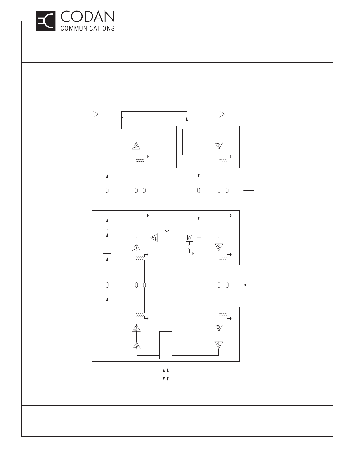
TN150 Repeater / Tone Remote Controlled Base Station
RJ45 Cable
LVDS Serial Data +
Analog and Digital
COR-PTT Routing
(Required for P25
Digital Repeater)
1 KHz Tone @
60% of Max. Modulation
(1.5 KHz Narrowband
3.0 KHz Wideband)
1 KHz Tone @
60% of Max. Modulation
(1.5 KHz Narrowband
3.0 KHz Wideband)
ANALOG LVDS
TRANSMITTER
TX PTT INPUT
OPTICAL
AC-3E or CI-BC-4E
ISOLATOR
AUXILIARY
PTT (K) INPUT
PTT PTT
LEVEL ADJUST
AUDIO INPUT
TX BALANCED
AUXILIARY
BALANCED
AUDIO INPUT
-8.0 dBm
(307 mVrms)
0 dBm
(775 mVrms)
RECEIVER
Jumper
be used
with RJ45
(Must NOT
COR->PTT
to Disable
Audio Path
(Must be used
with RJ45 Cable
Jumper Installed
ANALOG LVDS
LEVEL ADJUST
COR
RX COR OUTPUT
Cable
Installed)
Installed)
AUXILIARY
RX BALANCED
BALANCED
-8.0 dBm
AUDIO OUTPUT
0 dBm
OUTPUT
(307 mVrms)
(775 mVrms)
ALL INTERNAL CONNECTIONS
AVAILABLE ON A-PNL-AUX96-3
OPTIONALLY AVAILABLE ON DB-25
CONNECTOR (VIA JUMPER SELECT)
(TYPICALLY USED FOR TEST PURPOSES)
and DB-25 CONNECTOR
AVAILABLE ON A-PNL-AUX96-3
ALL AUXILIARY CONNECTIONS
TX
RADIO
RX
LINE
TELEX (VEGA) DSP-223
TONE REMOTE ADAPTER
CONSOLE
TO / FROM
TONE REMOTE
TN150, REV 1-0-0, © Aug 2016
CANADA/US +1 250 382 8268 | TOLL FREE +1 800 664 4066
Page 2 of 2
LINE
2 or 4 WIRE
INPUT / OUTPUT
RX
RADIO
TX
LINE
CODANCOMMS.COMTECHNICAL NOTE:
LMRSALES@CODANCOMMS.COM
Page 13
TECHNICAL NOTES
A
MT-4 Radio Systems
TN151 Base Station Interface Connections
Base Stations can be interfaced to a console, or console network through a variety of technologies that have
changed considerably over the years.
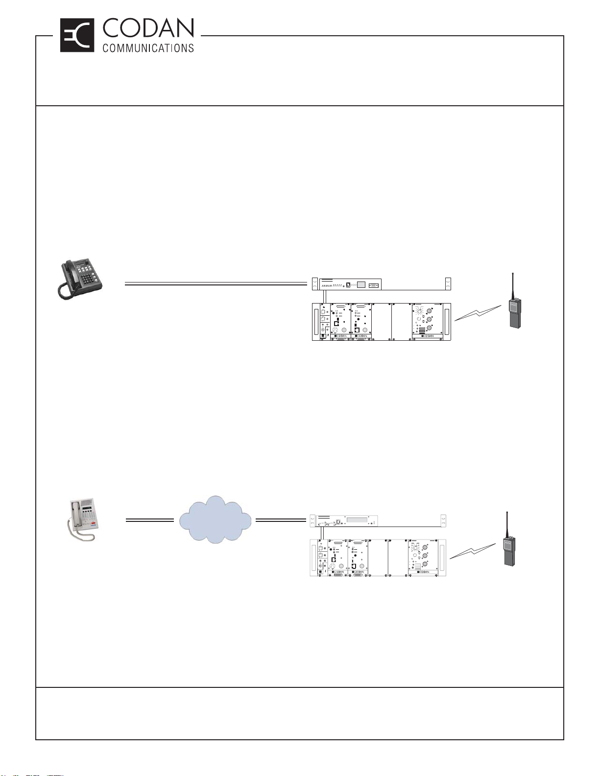
Analog Tone Remote Interface
An Analog Tone Remote Interface provides a means of remotely controlling base stations by any voice grade
transmission medium such as a microwave link, a leased telephone line, or a twisted-pair 600-ohm line. An
industry-standard sequential tone keying format is generated by the console and is sent over the transmission
medium to a tone remote adapter that is capable of decoding the PTT tone sequence and the voice-plus-tone
signals. The tone portion of the voice-plus-tone signal is removed from the transmitted voice by the adapter. A tone
remote base station interface is shown in Figure 1.
TELEX DSP-223 TONE
DSP-223
FUNCTION
HANDSET
PROGRAMMING PORT
POWER PTT MONITOR
RECEIVER
FREQUENCY (MHz)
AD
USB
CNTL
BUS
MADE IN CANADA
MODEL # CODE
SQ. DISABLE
NORM
OFF
REF
IN
RF NI
REMOTE ADAPTER
OR BASE CONTROL CARD
SPKR
FUNCTION
12
11
10
9
8
VOL METER
ON
OFF
INT
EXT
EXT
SPKR
SYSTEM REGULATOR
1
2
3
4
5
67
+
-
MADE IN CANADA
COMMON AIR
ANTENNA A
RX A
TX A
INTERFACE
P25 DIGITAL OR
ANALOG SUBSCRIBER
ANALOG 2 OR 4 WIRE AUDIO AND TONES
NALOG TONE REMOTE
CONSOLE
(LEASED TELEPHONE LINES)
Figure 1: Analog Tone Remote Interface
TELEX
X
TX
+
X
S
X
-
+
D
IO R
IO
S
TX
E R
E TX
N
D
D
S
TX
TX
O
RX
A
A
TC
IO R
IO TX
I
S
E
E
E
OU
LIN
LIN
R
R
C
D
D
D
A
TC
A
A
IN
IN
IN
L
R
C
L
R
GR
R
L
PTT IC
ANALOG AUDIO INTERFACE
TRANSMITTER
P25 BASE
CONTROL
FREQUENCY (MHz)
RX A
AD
REF
A
IN
5
13
BNK
NORM
OFF
B
KEY TX
9
ANALOG
MICMODE
DIGITAL
TX A
A
5
13
BNK
USB
B
9
TX A TX B
CNTL
Secure
BUS
Clear
Local
MIC RF OUT
Enable
Disable
Zeroize
Key
PULL DOWN
TO REMOVE
MADE IN CANADA
MODEL # CODE
CODAN RADIO SYSTEM WITH AUDIO CARD
IP Network Remote Interface
An IP Network Remote Interface provides a means of remotely controlling base stations by any available Wide
Area Network (WAN) or Local Area Network (LAN) IP connection. This creates a Radio over IP (RoIP) network to
allow any Telex IP based console to communicate with the Telex IP Network adapter. Audio and control information
is encoded and decoded in a proprietary format over the network and converted back to analog audio and control
information (PTT) at the interface between the base station and adapter. The Telex IP network solution provides
voice and control over IP, but it is not end-to-end digital, or open standard. An IP network remote base station
interface is shown in Figure 2.
TELEX IP-223 OR IP-224
IP-223
IC
TX
LINE
LNK
IP REMOTE ADAPTER
RECEIVER
FREQUENCY (MHz)
AD
SQ. DISABLE
NORM
OFF
REF
IN
USB
RF NI
CNTL
BUS
MADE IN CANADA
MODEL # CODE
OR BASE CONTROL CARD
SPKR
FUNCTION
12
11
10
9
8
VOL METER
ON
OFF
INT
EXT
EXT
SPKR
SYSTEM REGULATOR
67
+
-
COMMON AIR
ANTENNA A
1
2
3
4
5
RX A
TX A
MADE IN CANADA
INTERFACE
P25 DIGITAL OR
ANALOG SUBSCRIBER
TELEX IP BASED
CONSOLE
LAN / WAN
TELEX PROPRIETARY DIGITAL IP INTERFACE
TELEX
HANDSET
X
X
X-
GND
TX-
TX
TX+
TX+
T
R
T
RX
RADIO 1 RADIO 2
ANALOG AUDIO INTERFACE
TRANSMITTER
P25 BASE
CONTROL
FREQUENCY (MHz)
RX A
AD
REF
A
IN
5
13
BNK
NORM
OFF
B
KEY TX
9
ANALOG
MICMODE
DIGITAL
TX A
A
5
13
BNK
USB
B
9
TX A TX B
CNTL
Secure
BUS
Clear
Local
MIC RF OUT
Enable
Disable
Zeroize
Key
PULL DOWN
TO REMOVE
MADE IN CANADA
MODEL # CODE
CODAN RADIO SYSTEM WITH AUDIO CARD
Figure 2: IP Network Remote Interface
In an analog tone remote and IP network remote, all P25 Digital communications are vocoded and de-vocoded at
the base station. This means that the interface does not support end-to-end encryption, P25 Digital ID’s or packet
data, to or from the console and base station.
TN151, REV 2-0-0, © Nov 2018
CANADA/US +1 250 382 8268 | TOLL FREE +1 800 664 4066
LMRSALES@CODANCOMMS.COM
CODANCOMMS.COMTECHNICAL NOTE:
Page 1 of 2
Page 14
TECHNICAL NOTES
MT-4 Radio Systems
TN151 Base Station Interface Connections
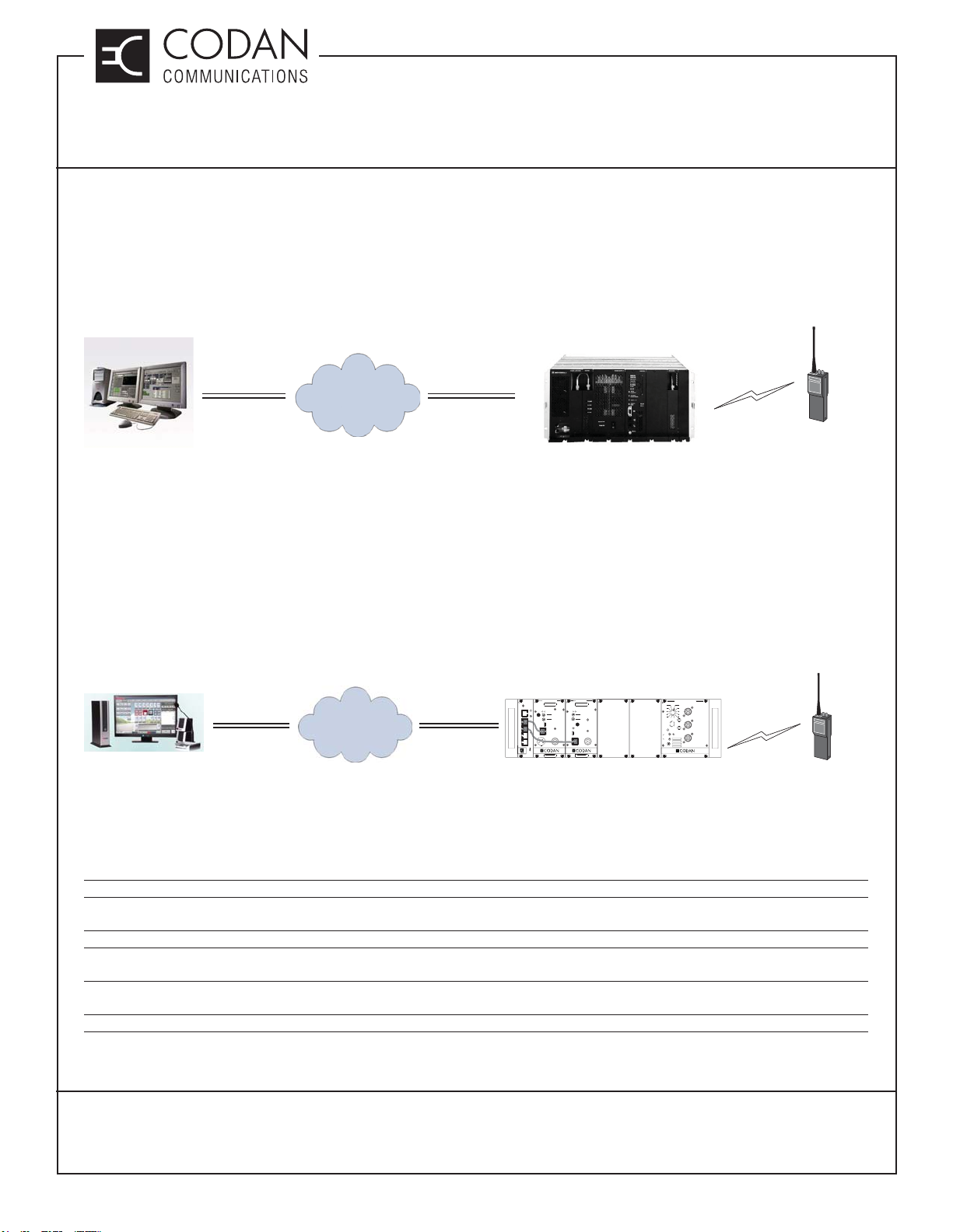
Proprietary IP Network Interface
A Proprietary IP Network Interface provides a means of remotely controlling one manufacturer’s base stations
by any available WAN or LAN IP connection. This creates a single vendor end-to-end digital RoIP network that
restricts interoperability, system fl exibility and competition. A proprietary IP network remote base station interface
is shown in Figure 3.
COMMON AIR
INTERFACE
LAN / WAN
P25 DIGITAL OR
MOTOROLA CENTRACOM
MOTOROLA PROPRIETARY DIGITAL IP INTERFACE
GOLD ELITE CONSOLE
Figure 3: Proprietary IP Network Interface
MOTOROLA QUANTAR
ANALOG SUBSCRIBER
P25 Open Standard Digital Fixed Station Interface (DFSI)
A P25 Open Standard Digital Fixed Station Interface (DFSI) provides a means of remotely controlling base stations
by any available WAN or LAN IP connection. This creates a multi-vendor platform end-to-end digital RoIP network
that supports full interoperability, system fl exibility and competitive pricing between vendors. A DFSI interface fully
supports end-to-end encryption, P25 Digital ID’s and packet data, to or from the console and base station. A DFSI
network remote base station interface is shown in Figure 4.
TRANSMITTER
P25 DFSI CONSOLE
LAN / WAN
P25 DIGITAL FIXED STATION INTERFACE
UIC
ETHERNET
TX A
RX A
ZEROIZE
KEY
TX B
RX B
PULL DOWN
TO REMOVE
RECEIVER
FREQUENCY (MHz)
FREQUENCY (MHz)
AD
AD
REF
IN
NORM
SQ. DISABLE
OFF
KEY TX
NORM
ANALOG
MICMODE
DIGITAL
OFF
REF
USB
MIC RF OUT
MADE IN CANADA
MODEL # CODE
IN
USB
RF NI
CNTL
BUS
MADE IN CANADA
MODEL # CODE
CNTL
BUS
CODAN RADIO SYSTEM WITH UIC
SPKR
FUNCTION
12
11
10
9
8
VOL METER
ON
OFF
INT
EXT
EXT
SPKR
SYSTEM REGULATOR
1
2
3
4
5
67
+
-
MADE IN CANADA
ANTENNA A
RX A
TX A
COMMON AIR
INTERFACE
P25 DIGITAL OR
ANALOG SUBSCRIBER
Figure 4: P25 Open Standard Digital Fixed Station Interface (DFSI)
P25 DFSI advantages over IP-223 / IP-224 Devices
• DFSI is an open standard multi-vendor protocol platform. IP-223/224 is a proprietary protocol.
• DFSI supports a direct digital interface to the Codan Base Station via IP. The IP-223/224 is an IP connection to an analog gateway (IP-223/224) that
connects to the Codan Base Station via analog audio.
• DFSI supports full encrypted P25 voice to the console. An IP-223/224 will not transport encryption over the network.
• DFSI supports Single Block Commands as defi ned in the TIA-102 standards such as Radio Inhibit, Call Alert, Radio Monitor, Radio Check, etc. IP-
223/224 does not.
• IP-223 /224 requires a radio technician to tune analog audio levels in both the Codan Base Station and IP-223/224. DFSI is a direct digital interconnect
with no line level adjustments.
• DFSI supports the ability to upgrade to P25 Packet Data support such as GPS, Key Management, and othercapabilities. IP-223/224 does not.
TN151, REV 2-0-0, © Nov 2018
CANADA/US +1 250 382 8268 | TOLL FREE +1 800 664 4066
Page 2 of 2
CODANCOMMS.COMTECHNICAL NOTE:
LMRSALES@CODANCOMMS.COM
Page 15
TECHNICAL NOTES
MT-3/4 Radio Systems
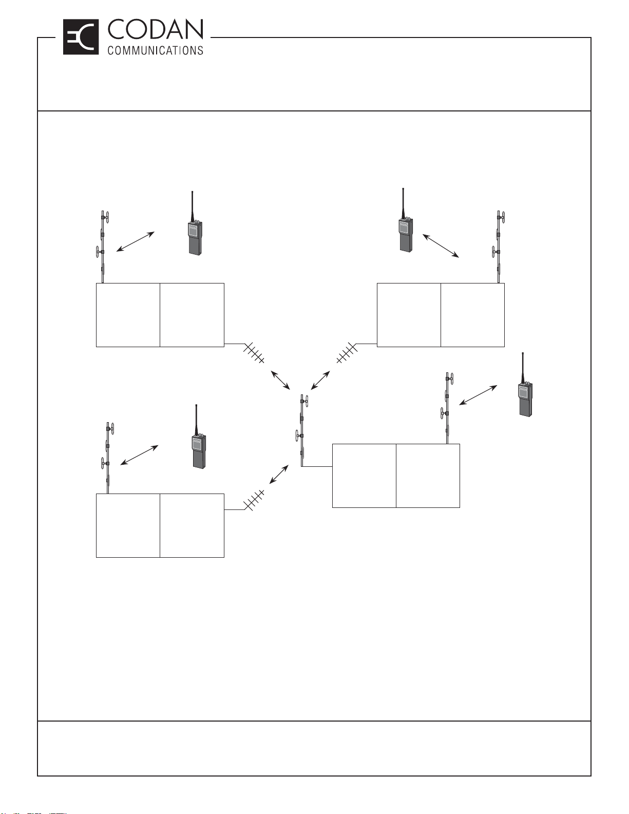
TN152 Linked Repeater Networks
A linked repeater network is a series of repeaters that are linked together through RF links to create a wide area
conventional repeater network that allows for a widely confi gurable system with an expandable area of coverage
for mobile and portable radios (subscribers).
A linked repeater network can be installed as a fi xed network infrastructure, and can also be fully transportable. A
transportable linked repeater network is self-healing (linked repeaters can be added or removed at any time) and
is easily deployable and fi eld agile.
A linked repeater network is available as an analog only or analog and P25 digital (mixed mode) repeater network
giving the users full forwards and backwards compatibility with existing legacy equipment. In P25 Digital mode,
all encrypted voice and data will pass transparently through the repeater network. The repeaters do not require or
contain any encryption in order to pass the encryption through the repeater and links.
Repeaters and links can be any frequency band (VHF, UHF, 700/800/900 MHz). One common example is to have
VHF repeaters with UHF links.
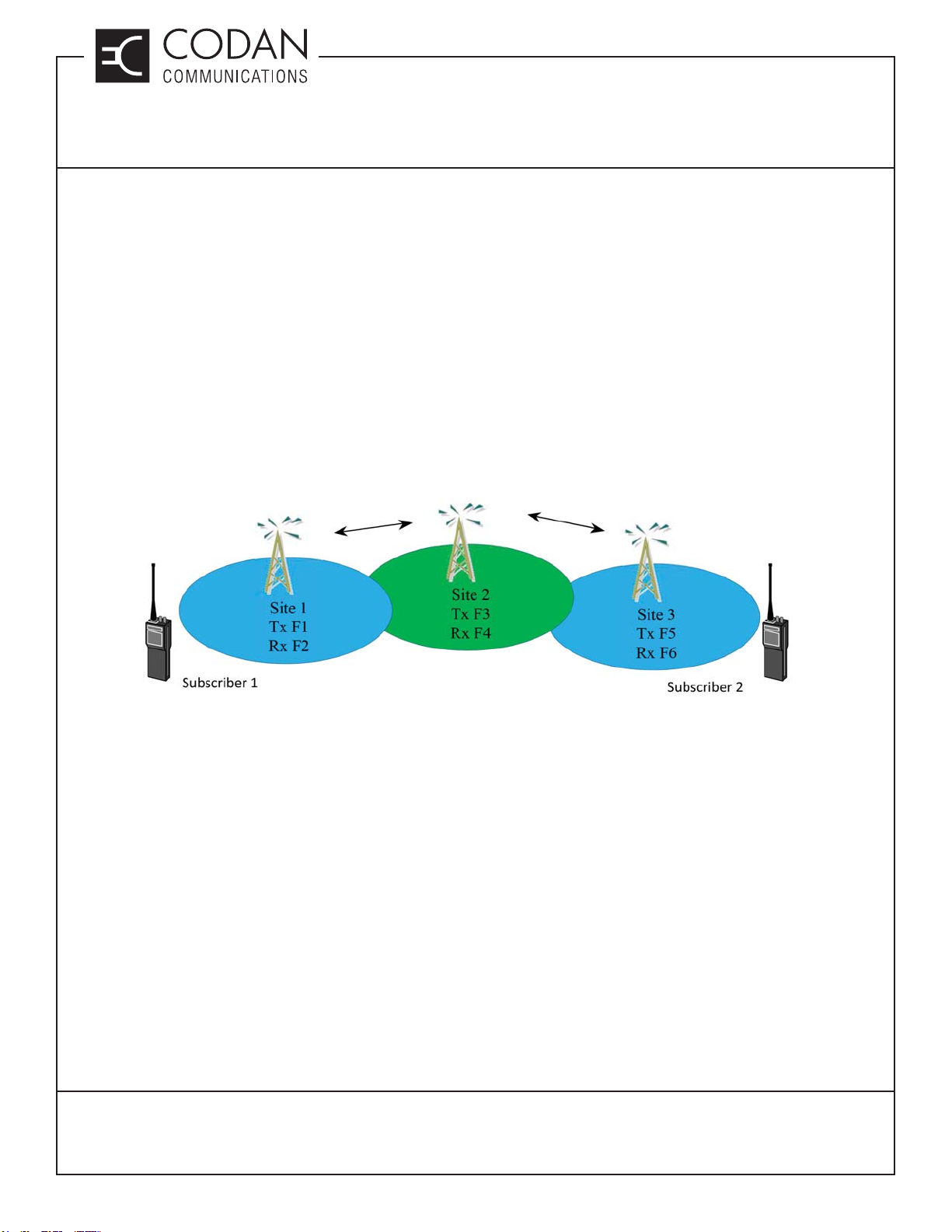
Figure 1: Linked Repeater Network Diagram
A linked repeater network can be confi gured as two or more separate repeaters connected together. Figure 1
shows a system of three linked repeaters in use. Each repeater provides radio coverage for a local geographic
region utilizing a diff erent transmit / receive frequency pair. The repeater sites are RF linked together such that
transmitted information from Subscriber 1 is received at Site1, then linked to and rebroadcast from each repeater
in the system, allowing Subscriber 2 to receive the information from Site 3. This allows each subscriber to transmit
information to any other subscriber anywhere on the network.
The term Drop-Link is sometimes used to describe the repeater (drop) and the link in a linked repeater network.
HiveNet is also a term sometimes used to describe a linked repeater network.
TN152, REV 1-0-0, © Jan 2019
CANADA/US +1 250 382 8268 | TOLL FREE +1 800 664 4066
LMRSALES@CODANCOMMS.COM
CODANCOMMS.COMTECHNICAL NOTE:
Page 1 of 4
Page 16
TECHNICAL NOTES
MT-3/4 Radio Systems
TN152 Linked Repeater Networks
Technical Description
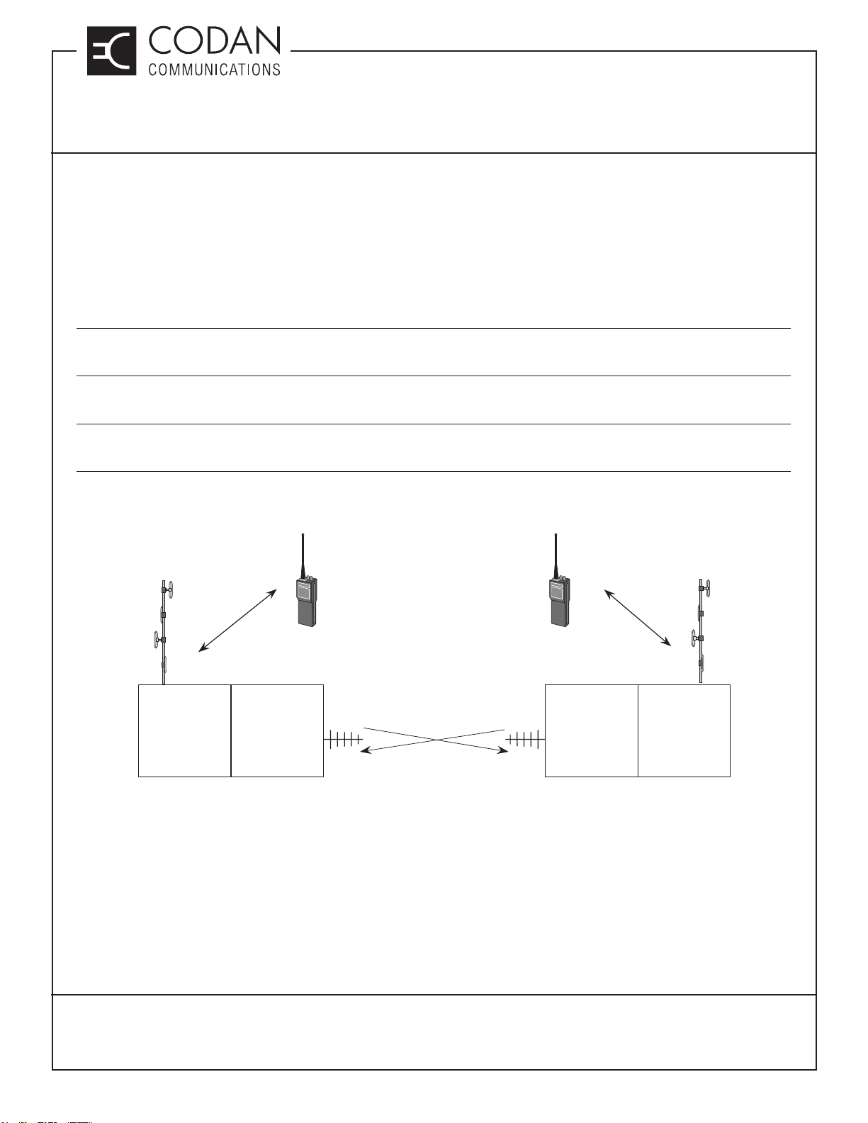
Linked repeaters are made up of two transceivers, the repeater (sometimes referred to as the “Drop”), and the
Link. The Drop repeaters are on separate frequencies, while the link frequencies are matched (and reversed).
Figure 2 shows two repeaters linked together with frequency pairs. The Link is referred to as a “Switched Link”,
meaning that the receiver and transmitter are never active at the same time.
A Switched Link is typically half-duplex, allowing use of a duplexer or antenna relay for the antenna connection.
• An antenna relay allows for a more frequency agile link, transceiver frequencies can be changed without the
need for any duplexer retuning.
• A duplexer allows the Switched Link to be changed to a Repeating Link if the system needs to be expanded for
more linked repeaters.
• Simplex (same) frequencies can also be used on a two site Switched Link repeater with an antenna relay, but
every linked repeater must Link directly to each other (no “Chains” of links).
The use of diff erent repeaters all transmitting at the same time on diff erent frequencies is called multicasting.
To / From
Subscribers
To / From
Subscribers
Site 1 Site 2
Drop
Tx-F1
Rx-F2
Figure 2: Network of Two Repeaters
Switched link
Tx-F3
Rx-F4
Switched link
Tx-F4
Rx-F3
Drop
Tx-F5
Rx-F6
TN152, REV 1-0-0, © Jan 2019
CANADA/US +1 250 382 8268 | TOLL FREE +1 800 664 4066
Page 2 of 4
CODANCOMMS.COMTECHNICAL NOTE:
LMRSALES@CODANCOMMS.COM
Page 17
TECHNICAL NOTES
MT-3/4 Radio Systems
TN152 Linked Repeater Networks
Linked repeaters can be linked together to form diff erent confi gurations depending on requirements. For larger
systems a repeating link may be required as a centralized “hub” for the network as shown in Figure 3. Repeating
Links are full duplex and require a duplexer for the antenna connection, and possibly multiple antennas with a
power splitter or a multi-directional antenna.
To / From
Subscribers
Site 1 Site 2
Drop Switched link
Tx-F1
Rx-F2
To / From
Subscribers
Site 3
Drop
Tx-F3
Rx-F4
Site 4
Repeating
link
Tx-F4
Rx-F3
Switched link
Tx-F3
Rx-F4
Drop
Tx-F7
Rx-F8
To / From
Subscribers
DropSwitched link
Tx-F5
Rx-F6
To / From
Subscribers
Tx-F9
Rx-F10
Figure 3: Network of Four Repeaters
TN152, REV 1-0-0, © Jan 2019
Tx-F3
Rx-F4
CANADA/US +1 250 382 8268 | TOLL FREE +1 800 664 4066
CODANCOMMS.COMTECHNICAL NOTE:
LMRSALES@CODANCOMMS.COM
Page 3 of 4
Page 18
TECHNICAL NOTES
MT-3/4 Radio Systems
TN152 Linked Repeater Networks
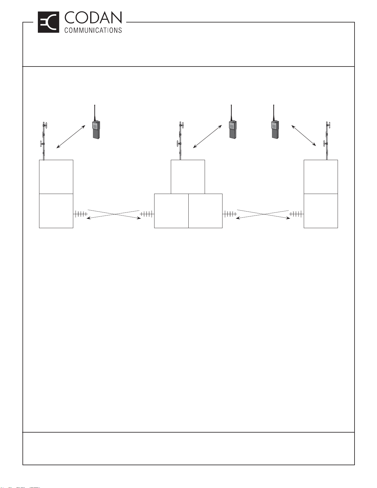
Some linked repeater confi gurations may also require multiple switched links in order to form a “chain” of repeater
links as shown in Figure 4. This requires another set of frequencies and another transceiver pair, but can allow
more customizing of the confi guration.
To / From
Subscribers
Site 1
Drop
Tx-F1
Rx-F2
Switched link
Tx-F7
Rx-F8
Figure 4: Repeater Network with Multiple Links
Drop
Tx-F3
Rx-F4
Switched link
Tx-F8
Rx-F7
To / From
Subscribers
Site 2 Site 3
Switched link
Tx-F10
Rx-F9
To / From
Subscribers
Drop
Tx-F5
Rx-F6
Switched link
Tx-F9
Rx-F10
TN152, REV 1-0-0, © Jan 2019
CANADA/US +1 250 382 8268 | TOLL FREE +1 800 664 4066
Page 4 of 4
CODANCOMMS.COMTECHNICAL NOTE:
LMRSALES@CODANCOMMS.COM
Page 19
TECHNICAL NOTES
MT-3/4 Radio Systems
TN160 Base Station or Link Confi guration Settings
When confi guring a Codan radio system for base station operation or for a linked confi guration, certain settings,
such as jumpers, may need to be installed to allow the base station or link to operate properly.
The receiver and transmitter modules are used with specifi c control cards to facilitate the external connections of a
base station, or to allow the complex connectivity of a linked system. The MT-3 modules are connected to an AC-3E
Audio Control Card and the MT-4 modules are connected to a CI-BC-4E Base Controller for base station operation,
or a CI-RC-4L Repeater Controller or CI-RC-4M-G2 Multiple Link Controller for a linked system. The A-PNLAUX96-3 auxiliary connector is recommended for facilitating all external connections in a base confi guration.
Antenna Relay Activation
The System Regulator module may have up to two optional antenna relays installed that can be used for a base
station or simplex / half-duplex link confi guration. The antenna relays are labeled as Relay A and Relay B (if only
one relay is installed, it is Relay A). The motherboard on the subrack contains a set of jumpers that are used to
activate the optional antenna relays in the System Regulator module. The relays are typically set with the PTT IN
and PTT OUT signal lines activating the relays.
Jumpers function as follows:
JU36 Tx A PTT OUT activates Relay A JU37 Tx A PTT IN activates Relay A
JU39 Tx A PTT OUT activates Relay B JU40 Tx A PTT IN activates Relay B
JU42 Tx B PTT OUT activates Relay A JU43 Tx B PTT IN activates Relay A
JU45 Tx B PTT OUT activates Relay B JU46 Tx B PTT IN activates Relay B
On older motherboards (Serial # 123125 and earlier) the jumpers were as follows:
JU16 Tx A PTT OUT activates Relay A JU12 Tx A PTT IN activates Relay A
JU14 Tx A PTT OUT activates Relay B JU10 Tx A PTT IN activates Relay B
JU15 Tx B PTT OUT activates Relay A JU11 Tx B PTT IN activates Relay A
JU13 Tx B PTT OUT activates Relay B JU9 Tx B PTT IN activates Relay B
Simplex Operation
The motherboard on the subrack contains a set of jumpers that are enabled when the radio system is operated in
simplex mode (simplex base station or simplex links). The jumper connects the Transmitter PTT OUT signal line to
the RX MUTE. This jumper will cause the receiver to mute when the transmitter is keyed.
JU38 Tx A PTT OUT mutes Rx A JU41 Tx A PTT OUT mutes Rx B
JU44 Tx B PTT OUT mutes Rx A JU47 Tx B PTT OUT mutes Rx B
The new System Regulators also have the same simplex mode jumpers for backwards compatibility with older
motherboards that did not have these jumpers. The jumpers were located on the old System Monitor as follows:
JU12 Tx A PTT OUT mutes Rx A JU13 Tx B PTT OUT mutes Rx B
TN160, REV 5-0-0, © Nov 2018
CANADA/US +1 250 382 8268 | TOLL FREE +1 800 664 4066
LMRSALES@CODANCOMMS.COM
CODANCOMMS.COMTECHNICAL NOTE:
Page 1 of 2
Page 20

TECHNICAL NOTES
MT-3/4 Radio Systems
TN160 Base Station or Link Confi guration Settings
Control Card Simplex Operation
When a control card with LVDS Serial Data interconnect is used for the radio confi guration, the simplex muting
jumpers in the control card should be used in place of the jumpers on the motherboard. The jumpers on the control
cards activate faster than the jumpers on the motherboard
The CI-RC-4M-G2 Multiple Link Controller can be set for simplex link operation in the software under the System
Settings tab, but requires the MUTE line to be connected from the subrack to the controller.
The CI-RC-4L Repeater Control Card can be set for simplex link operation via the jumpers in the control card.
Simplex Operation Improvement
On some simplex base or link systems, the Rx MUTE line may be released too quickly after the Tx PTT is deactivated.
The RF signal has not had enough time to decay before the receiver is un-muted and this can produce an audible
noise burst or blip at the end of each transmission.
MT-3 Systems require that two resistors within the receivers be replaced with 47K ohm resistors (1150-4B1002FP).
R95 and R96 require replacement in FM receivers. AM receivers require that R35 and R83 are replaced.
MT-4E Systems have a software selectable Simplex Unmute Delay jumper setting that can be enabled in the RSS
software Service section.
MT-4D Systems require that JU33 is installed in the Y position in the receivers.
MT-4R Systems require a 4.7 uF capacitor (1055-5B475K16) to be added to the PTT OUT signal line. This
modifi cation was part of ECO 758. Any transmitters that were sold before, and have not been returned to the factory
since March 2003, will require this modifi cation for simplex operation.
MT-4R or MT-4D Base Station with Telex (Vega) DSP-223 Control
If an MT-4R or MT-4D base station is operated by a console other than a Telex product, through a Telex DSP-223
tone remote adapter, there is a possibility the transmitter may not change channels properly (only changing channels
every second time the PTT is activated at the console).
If the MT-4R or MT-4D system is being controlled by a CI-BC-4E Base Controller, JU125 is required to be installed
in the controller.
If the MT-4R or MT-4D system is being controlled by an AC-3E Audio Control Card (not recommended), a 22 uF
capacitor (1054-6G226M20) is required to be added by soldering the positive lead to J23 and the negative lead to
ground.
TN160, REV 5-0-0, © Nov 2018
CANADA/US +1 250 382 8268 | TOLL FREE +1 800 664 4066
Page 2 of 2
CODANCOMMS.COMTECHNICAL NOTE:
LMRSALES@CODANCOMMS.COM
Page 21
TECHNICAL NOTES
MT-4 Radio Systems
TN175 MT-4E Firmware Upgrading
Codan Communications allows customers to upgrade the fi rmware of their MT-4E Receivers and Transmitters
via the Firmware Flashing Software and Firmware Upgrade fi les. The Firmware Flashing Software and Firmware
upgrade fi les are all available at the Codan website www.codancomms.com under Support - Software & Firmware.
It is not necessary to upgrade the fi rmware if the equipment is installed and is operating satisfactory. A fi rmware
upgrade is typically only needed to fi x minor software bugs or to upgrade the functionality of the equipment.
Firmware versions earlier than 1.6.0 must be returned to the factory for upgrading. Firmware version 1.6.0 and
1.7.0 may need to be returned to the factory for minor hardware upgrades. Contact the Codan service department
for more information.
Instructions
Please read all of these instructions before beginning the Firmware Flashing process.
Download the Firmware Flashing Software and appropriate Firmware upgrading fi les to a PC running a Windows
XP (or higher) operating system before beginning the upgrading procedure.
Choosing the Appropriate Firmware Upgrading Files
MT-4E Receivers and Transmitters can be purchased as an analog radio, or they can be purchased with the P25
Digital radio fi rmware package. If the radio is Analog only, download the Analog fi rmware upgrade, if it is P25 Digital
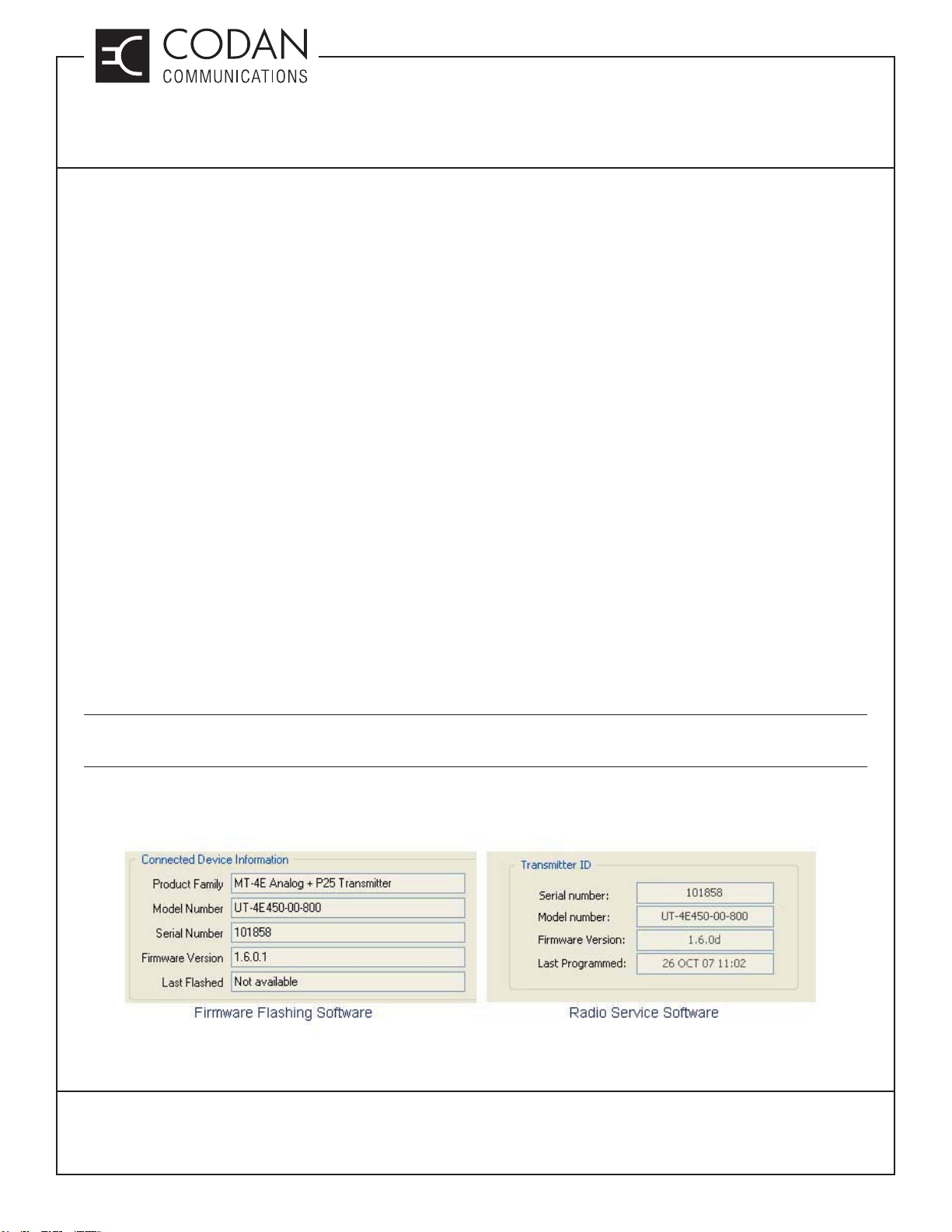
(and Analog) capable, download the Digital fi rmware upgrade. To determine if the MT-4E Receiver or Transmitter
is Analog only or P25 Digital, read the fi rmware version of the module using the Firmware Flashing Software or the
Radio Service Software as shown in Figure 1. If the last digit of the fi rmware version is an “a” or “0”, the fi rmware is
Analog only, if the last digit is a “d” or “1”, the fi rmware is P25 Digital and Analog.
NOTE: The Firmware Flashing Software will not allow you to program an MT-4E Receiver or Transmitter with the
wrong fi rmware upgrade
Figure 1: Version Number Examples
TN175, REV 4-0-0, © Aug 2016
CANADA/US +1 250 382 8268 | TOLL FREE +1 800 664 4066
CODANCOMMS.COMTECHNICAL NOTE:
LMRSALES@CODANCOMMS.COM
Page 1 of 4
Page 22
TECHNICAL NOTES
MT-4 Radio Systems
TN175 MT-4E Firmware Upgrading
Download the latest fi rmware version (Analog or Digital) from the website for both the receiver and transmitter. If
the current fi rmware version of the MT-4E Receiver or Transmitter is 1.6.0 or 1.7.0, an additional Bootloader and
Version 2.0.0 fi rmware (Analog or Digital) will also need to be downloaded.
Using the Firmware Flashing Software
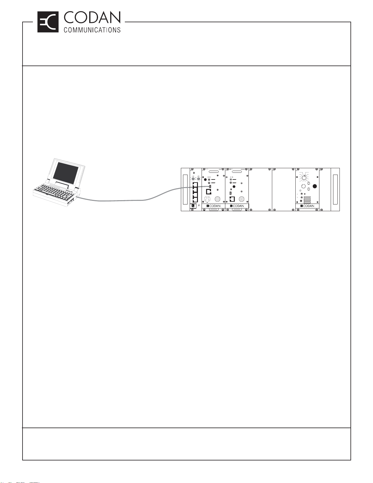
Start the Firmware Flashing Software application and turn on the MT-4E Receiver or Transmitter. Using a USB type
A to 5 pin mini-type B cable (the same USB cable used to program the modules), connect the USB port of the PC
to the USB port on the front panel of the MT-4E Receiver or Transmitter module as shown in Figure 2.
NORM
OFF
KEY TX
ANALOG
DIGITAL
RECEIVER
FREQUENCY (MHz)
AD
SQ. DISABLE
NORM
OFF
REF
IN
USB
RF NI
CNTL
BUS
MADE IN CANADA
MODEL # CODE
SYSTEM REGULATOR
12
11
10
9
8
VOL
ON
OFF
SPKR
INT
EXT
EXT
SPKR
FUNCTION
67
+
METER
-
MADE IN CANADA
1
2
3
4
5
POWER
ON
OFF
USB CABLE
REPEATER
CONTROL
SWITCH A SWITCH B
15
13
11
9
TRANSMITTER
FREQUENCY (MHz)
AD
REF
15
3
3
IN
5
11
7
7
9
MICMODE
TX A
USB
RX A
CNTL
BUS
TX B
MIC RF OUT
RX B
PULL DOWN
TO REMOVE
MADE IN CANADA
MODEL # CODE
Figure 2: PC to Radio USB Connection
An information window will appear stating that the existing fi rmware in the radio is out of date and needs to be
upgraded. Click OK to close this window.
If the current fi rmware version of the MT-4E Receiver or Transmitter is 1.6.0 or 1.7.0 a Bootloader dialog box will
appear. See the section on upgrading Firmware version 1.6.0 and 1.7.0. If the current fi rmware version is 2.1.0 or
higher, the Firmware Flashing Software can upgrade the fi rmware immediately to the next fi rmware version without
the Bootloader.
TN175, REV 4-0-0, © Aug 2016
CANADA/US +1 250 382 8268 | TOLL FREE +1 800 664 4066
Page 2 of 4
CODANCOMMS.COMTECHNICAL NOTE:
LMRSALES@CODANCOMMS.COM
Page 23
TECHNICAL NOTES
MT-4 Radio Systems
TN175 MT-4E Firmware Upgrading
Flashing the Firmware
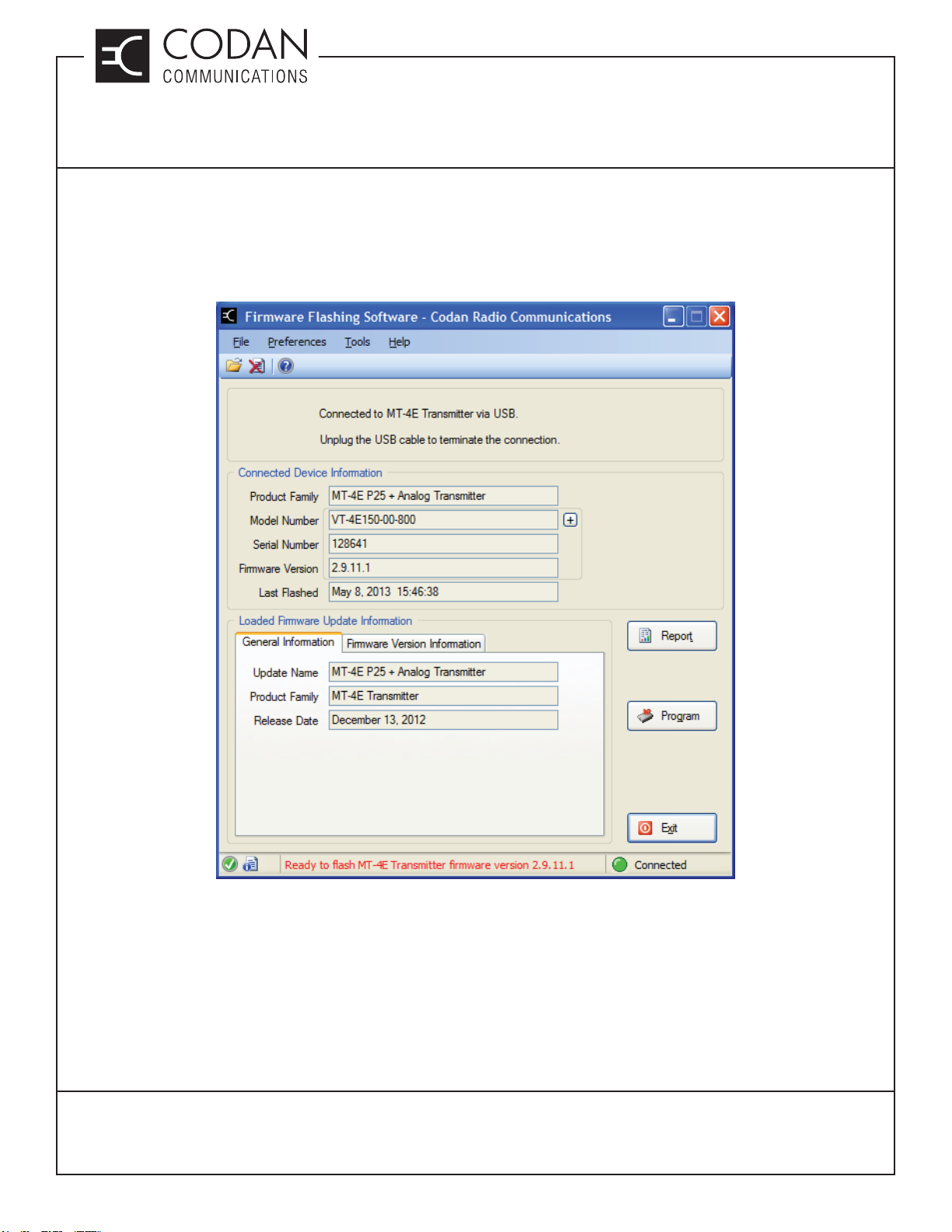
To apply the fi rmware upgrade (or Bootloader), click on File - Open and navigate to the directory where the fi rmware
upgrades are stored on your PC. Load the appropriate update fi le (Transmitter / Receiver; Analog only / Digital and
Analog; Bootloader / Firmware Version) as shown in Figure 3.
Figure 3: Firmware Flashing Software Example.
Click on the Program button to start the fi rmware update process. A dialog box will appear asking confi rmation to
proceed with the fi rmware update. A dialog box will also appear cautioning against interrupting the fl ashing process
in any way while the fi rmware is being updated. This is very important as any interruptions could cause the fi rmware
in the radio to be corrupted. Click on OK to proceed with the fi rmware update.
At the conclusion of the update the radio may need to be manually reset by cycling power to the module.
TN175, REV 4-0-0, © Aug 2016
CANADA/US +1 250 382 8268 | TOLL FREE +1 800 664 4066
LMRSALES@CODANCOMMS.COM
CODANCOMMS.COMTECHNICAL NOTE:
Page 3 of 4
Page 24
TECHNICAL NOTES
MT-4 Radio Systems
TN175 MT-4E Firmware Upgrading
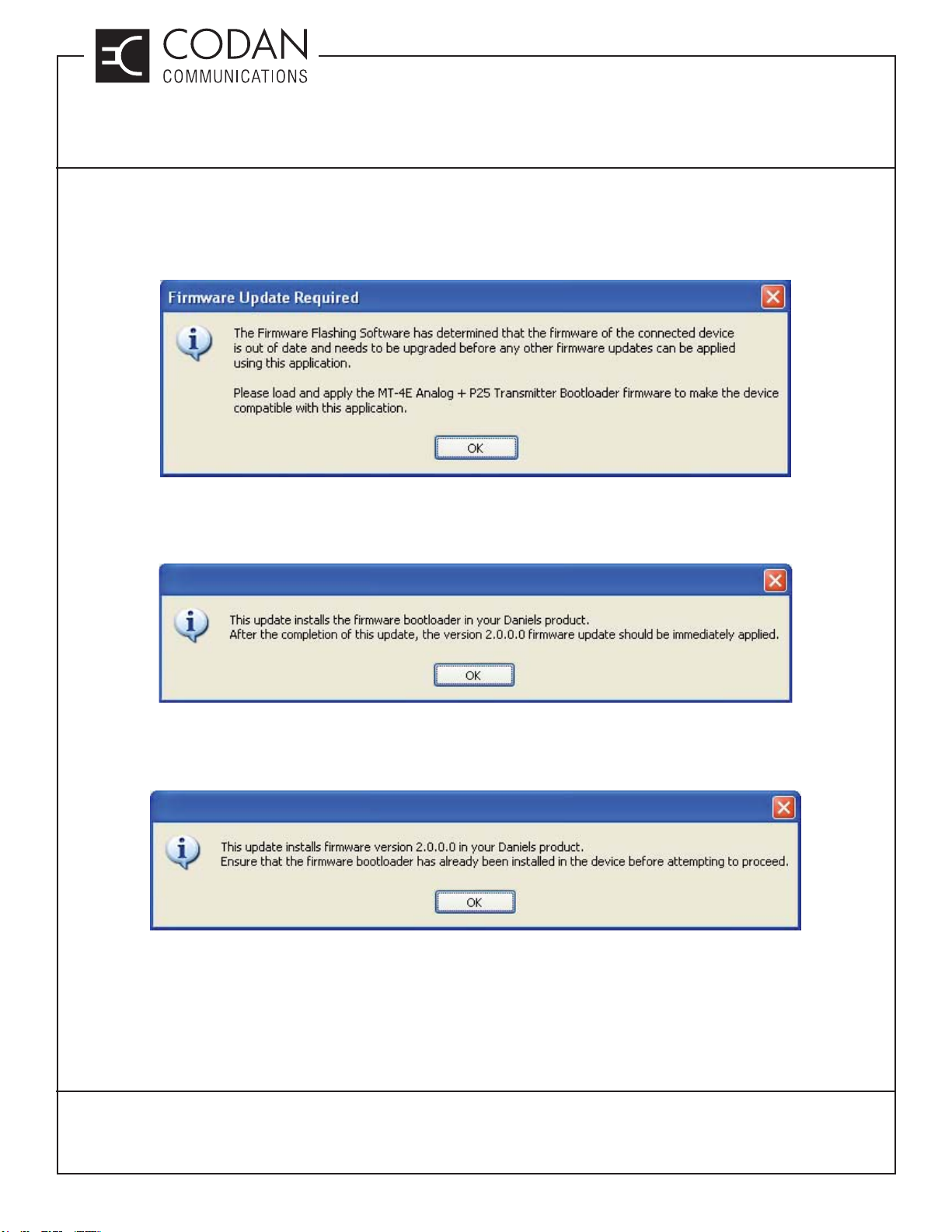
Upgrading Firmware version 1.6.0 and 1.7.0
If the current fi rmware version of the MT-4E Receiver or Transmitter is 1.6.0 or 1.7.0, a dialog box will appear as
shown in Figure 4, warning that the fi rmware is out of date and will require the Bootloader.
Figure 4: Version 1.6.0 and 1.7.0 Warning Dialog Box
Once the Bootloader is applied, the module’s fi rmware will appear as version 0.0.0. Firmware Version 2.0.0 is
required to be installed next and a dialog box will appear as shown in Figure 5.
Figure 5: Bootloader Warning Dialog Box
When installing Version 2.0.0, another dialog box will appear as shown in Figure 6, warning that the Bootloader
must have been applied before proceeding.
Figure 6: Version 2.0.0 Warning Dialog Box
Bringing the MT-4E Receiver or Transmitter module up to Firmware Version 2.0.0 is a two-step process, which is
required in order to apply any further fi rmware upgrades. Once this two-step process is completed, it will not be
required again. Firmware Version 2.0.0 is a “blank” fi rmware version and must be upgraded to the latest fi rmware
in order for the module to operate.
TN175, REV 4-0-0, © Aug 2016
CANADA/US +1 250 382 8268 | TOLL FREE +1 800 664 4066
Page 4 of 4
LMRSALES@CODANCOMMS.COM
CODANCOMMS.COMTECHNICAL NOTE:
Page 25
TECHNICAL NOTES
MT-4 Radio Systems
TN180 P25 Digital Ping Feature
A conventional radio system requires the users to set the subscriber radio on the frequency pair of the nearest
repeater by manually turning the channel selector knob. This requires more training and attention on the part of
the radio user.
Subscriber radios can be programmed to scan the repeater transmit frequencies to lock onto the repeater when it
is transmitting. Standard scanning results in the subscriber selecting and using the fi rst channel in the scan list it
fi nds an active (transmitted) signal. Since the repeater talk-out range is generally greater than the subscriber talkin range, standard scanning does not always result in the optimal channel (typically the closest repeater) for the
subscriber to operate on.
In Vote Scan operation, each channel is qualifi ed by measuring the received signal strength of each repeater at
the subscriber radio. The subscriber then votes from the repeater sites, selecting either the best signal or the fi rst
signal that exceeds a pre-programmed received level threshold.
In order to keep the subscriber locked onto the best (typically closest) repeater site when the subscriber is keyed,
the repeaters need to have traffi c on the transmitter regularly. Since the radio users may not have consistent radio
traffi c, a Codan repeater can be programmed to ping after an inactive time interval allowing the vote-scanning
subscriber radios to lock onto the best repeater. The ping uses the P25 standard “silent” message, so that users
will not hear the radio traffi c, but it will activate the vote-scan capability in the subscriber.
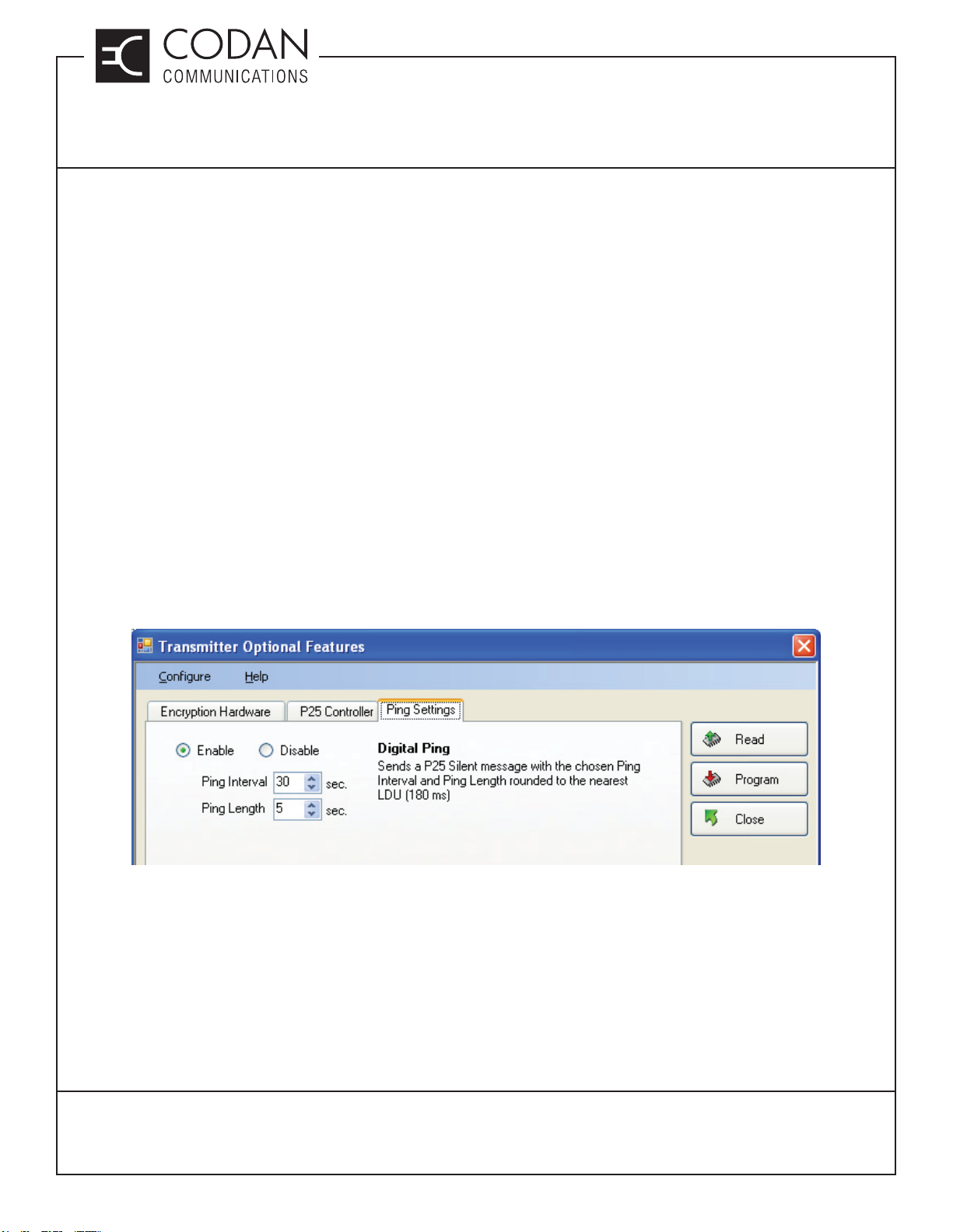
The optional digital ping software timer is confi gured to key the transmitter after a specifi ed time (interval) with no
activity, with a message of programmable duration (length) as shown in Figure 1.
Figure 1: Optional P25 Digital Ping Feature
Ping Interval range: 10 sec to 120 secs.
Ping Length: 1 sec to 15 secs (rounded to nearest LDU length – 180 mS)
The maximum Ping Length is less than 50% Ping Interval. e.g. Ping length < 5s if Ping interval set to 10s.
Setting the Ping Interval to a small value and the Ping Length to a large value will cause excessive network traffi c.
TN180, REV 1-0-0, © Aug 2016
CANADA/US +1 250 382 8268 | TOLL FREE +1 800 664 4066
CODANCOMMS.COMTECHNICAL NOTE:
LMRSALES@CODANCOMMS.COM
Page 1 of 2
Page 26

TN180 P25 Digital Ping Feature
This Page Intentionally Left Blank
TECHNICAL NOTES
MT-4 Radio Systems
TN180, REV 1-0-0, © Aug 2016
CANADA/US +1 250 382 8268 | TOLL FREE +1 800 664 4066
Page 2 of 2
CODANCOMMS.COMTECHNICAL NOTE:
LMRSALES@CODANCOMMS.COM
Page 27

TECHNICAL NOTES
MT-4 Radio Systems
TN181 Adjustable Courtesy Tone
An Adjustable Courtesy Tone option allows customization of the courtesy tone transmitted at the end of an analog
or P25 Digital transmission. The Adjustable Courtesy Tone is available in addition to the Fixed Courtesy Tone
implementation. The Radio Service Software (RSS) allows selection of either the fi xed or Adjustable Courtesy
Tone. If the Adjustable Courtesy Tone feature is disabed, the hang timer / courtesy tone will revert to it’s previous
(older fi rmware) method of programming and operation. This selection is made under Service->Courtesy Tone.
The Adjustable Courtesy Tone feature requires transmitter fi rmware version 2.10.9 (or higher) and RSS version
1.7.6 (or higher).
Figure 1: Adjustable Courtesy Tone
With the Adjustable Courtesy Tone, users may set diff erent courtesy tone settings for the following scenarios:
• transmission is shorter than a user programmable length
• transmission is longer than a user programmable length
• 13.8 Volt line (Supply Voltage) is below (or above) user programmable threshold #1.
• 13.8 Volt line (Supply Voltage) is below (or above) user programmable threshold #2.
• Courtesy Tone when input pin B14 or Z14 on the Transmitter module is asserted.
This is the MT-3 PTT NTO pin. Accessible as J1-3 (TX A PTT) for TXA and J1-11 (TX B PTT) for TXB on the
back panel Auxiliary connector (P1). Also, JU21 must be installed in the A position for TXA and JU20 must be
installed in the A position for TXB.
• Loss of Network condition
TN181, REV 1-0-0, © Mar 2017
CANADA/US +1 250 382 8268 | TOLL FREE +1 800 664 4066
LMRSALES@CODANCOMMS.COM
CODANCOMMS.COMTECHNICAL NOTE:
Page 1 of 2
Page 28

TECHNICAL NOTES
MT-4 Radio Systems
TN181 Adjustable Courtesy Tone
Setting the Adjustable Courtesy Tone
The priority level of each scenario can be independantly selected, or any scenarios can be individually disabled.
The priority arrangement must be the same for both analog and P25 digital mode.
The courtesy tone operation consists of 2 tones. Both tones can be programmed the same or diff erently or as
silent.
To have a silent tone in analog mode, simply set the volume of the tone to “0” or set the tone to 0 Hz. To have a
silent tone in P25 digital mode, set the tone frequency to 0 Hz.
The courtesy tone generated in analog mode is done after the pre-emphasis stage of the signal processing
chain of the transmitter. Therefore it will always come out as fl at audio response. Separate volumes controls are
provided for the fi rst and second tones in cases where the listening receiver is using de-emphasis.
In P25 mode, the following hang time behaviors are off ered:
• Silent Voice Frame Only
• Silent Voice Frame + Tone
• Simple Terminator Data Unit only (typically used for P25 encrypted calls)
• Simple Terminator Data Unit + Tone (typically used for P25 encrypted calls)
Sample tone setup for the Adjustable Courtesy Tone:
- Set the “Adjustable Courtesy Tone” option to ‘Enable’.
- Set the “Battery Reading Level 1 Trigger” to the low voltage trigger point. Such as 10 Vdc
- Set the “Battery Reading Level 2 Trigger” to the High voltage trigger point. Such as 17 Vdc
- In the Analog table set the two tones and level for the Battery Level 1 and 2.
- Set the Priority to 1 and all other priorities to 0 if the other settings are not used.
The transmitter will now send a two tone at the end of a transmission if the voltage goes below or above the
indicated voltage trigger point.
TN181, REV 1-0-0, © Mar 2017
CANADA/US +1 250 382 8268 | TOLL FREE +1 800 664 4066
Page 2 of 2
CODANCOMMS.COMTECHNICAL NOTE:
LMRSALES@CODANCOMMS.COM
Page 29
TECHNICAL NOTES
MT-4 Radio Systems
TN182 Battery Level Reporting and Remote P25 Test Tone
Battery Level Reporting is a method of activating a repeater remotely to have it transmit a signal that reports the
battery voltage level over RF. The Remote P25 Test Tone is a remotely activated Standard 1011 Hz P25 test tone
transmitted out of a repeater that allows a mobile coverage test to be done with a receiver performing a P25 Bit
Error Rate test.
Both the Battery Level Reporting and Remote P25 Test Tone are only available in a repeater confi guration with
a receiver connected to a transmitter through the front panel RJ45 Control bus. It can be a direct connection, or
through a CI-RC-4L repeater controller or a CI-RC-4M-G2 Multiple Link Controller. The Battery Level Reporting
and Remote P25 Test Tone are activated by a DTMF signal sent over RF to the repeater receiver.
The Battery Level Reporting and Remote P25 Test Tone features requires transmitter fi rmware version 2.10.9 (or
higher), receiver fi rmware version 2.9.8 (or higher) and RSS version 1.7.6 (or higher).
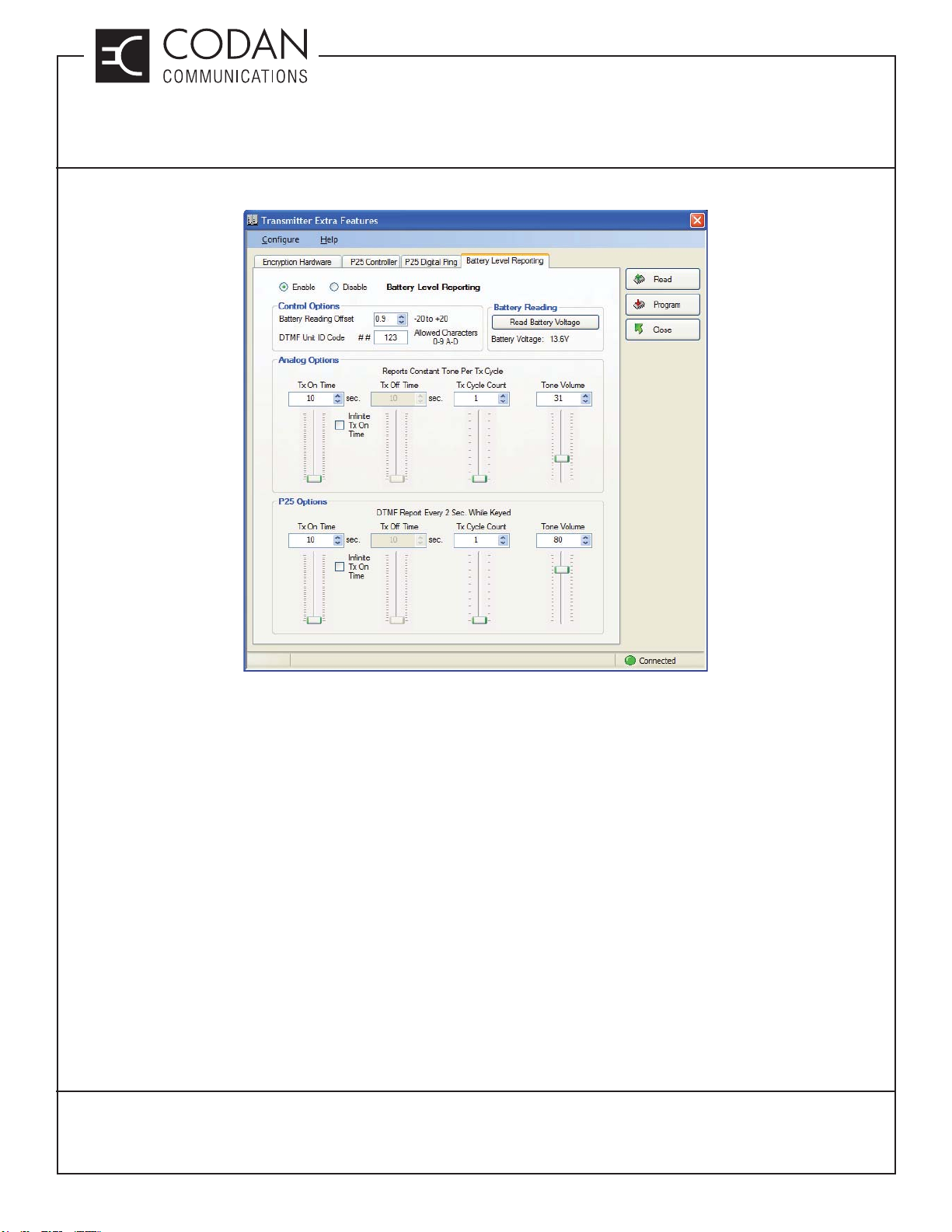
Battery Level Reporting
When the receiver receives a DTMF code of ##123 (or any three-digit programmed ID code), it will initiate the
transmitter with the corresponding three digit value (ID code of 123) to key up and transmit the battery level.
• The battery level is measured internally by the transmitter every two seconds.
• The battery reporting transmission can be stopped by another PTT from a subscriber radio.
• A DC off set adjustment (of the 13.8V line reading) is required for each transmitter. The procedure of this adjustment
is described in Battery Level Reporting DC Off set Adjustment Procedures.
Analog Mode
In analog mode, an audio tone that corresponds to the battery level of the repeater system is transmitted. For
example, a 1380 Hz tone transmitted over the air corresponds to a battery level of 13.80 Vdc.
• The duration of the reporting transmission is user programmable but has to be at least ten seconds.
• The deviation of the analog tone can be adjusted in the software as the tone volume.
P25 Digital Mode
In P25 digital mode a DTMF tone sequence that corresponds to the battery level of the repeater system is
transmitted. The battery level reporting is a DTMF tone sequence in the following format (in P25):
• Example - B125A123
• B marks the beginning of the battery level.
• The three 0 to 9 digits make up the battery level reporting.
• B125 means battery level of 12.5 Vdc
• A marks the beginning of the ID code of the transmitter reporting the battery level.
• The three 0 to 9 plus A, B, C, D digits is the ID code of the transmitter that reported the battery level.
• The number of times the battery report string transmits is user programmable but has to be at least two times.
• The duration of the silent P25 frame gap between each DTMF sequence is user programmable.
• The P25 Digital DTMF tone sequence volume can be adjusted in the tone volume.
TN182, REV 1-0-0, © Mar 2017
CANADA/US +1 250 382 8268 | TOLL FREE +1 800 664 4066
LMRSALES@CODANCOMMS.COM
CODANCOMMS.COMTECHNICAL NOTE:
Page 1 of 8
Page 30
TECHNICAL NOTES
MT-4 Radio Systems
TN182 Battery Level Reporting and Remote P25 Test Tone
Figure 1: Transmitter Battery Level Reporting
TN182, REV 1-0-0, © Mar 2017
CANADA/US +1 250 382 8268 | TOLL FREE +1 800 664 4066
CODANCOMMS.COMTECHNICAL NOTE:
LMRSALES@CODANCOMMS.COM
Page 2 of 8
Page 31

TECHNICAL NOTES
MT-4 Radio Systems
TN182 Battery Level Reporting and Remote P25 Test Tone
Remote Keying of 1011 Hz P25 Test Tone
This feature is only applicable to P25 digital mode. When the receiver receives a DTMF code of **123 (or any
three-digit programmed ID code), it will initiate the transmitter with the corresponding three digit value (ID code of
123) to key up and transmit the1011 Hz P25 Test Tone.
• ** marks the beginning of a DTMF command code for requesting remote keying of 1011 Hz test tone in P25 mode.
• The three 0 to 9 plus A, B, C, D digits is the ID code of the transmitter being requesting to do the remote keying
of 1011 test tone.
• The duration of the 1011 Hz P25 test tone transmission is user programmable (can be set to infi nite).
• The 1011 Hz P25 test tone transmission can be stopped by another PTT from a subscriber radio.
• The pattern being generate is the Standard Tone Test Pattern as per TIA-102.CAAA Section 1.3.3.7 a).
• This feature must be enabled via RSS for both the receiver and transmitter.
Figure 2: Transmitter Remote 1011 Test Tone
Figure 3: Receiver Remote 1011 Test Tone
TN182, REV 1-0-0, © Mar 2017
CANADA/US +1 250 382 8268 | TOLL FREE +1 800 664 4066
CODANCOMMS.COMTECHNICAL NOTE:
LMRSALES@CODANCOMMS.COM
Page 3 of 8
Page 32

TECHNICAL NOTES
MT-4 Radio Systems
TN182 Battery Level Reporting and Remote P25 Test Tone
Subscriber DTMF Requirements
In P25 digital mode, the subscriber is required to have the capability to generate DTMF in P25 Digital mode (not
all P25 equipment supports this capability).
In analog mode the DTMF implementation can vary between diff erent models of subscriber. As a consequence,
the analog DTMF decoder of each repeater receiver is required to be tuned to work with a particular subscriber
model. The procedure for this adjustment is described in the Receiver Analog DTMF Decoder Alignment Procedures.
More than one subscriber manufacturer / model may work, but to guarantee the best operation the most common
subscriber should be used to tune this feature. This is an issue with subscribers that Codan tries best to accommodate.
The subscriber and repeater also need to match the use of pre/de-emphasis or fl at audio.
Battery Level Reporting DC Off set Adjustment Procedures
Tools Required:
DC volt meter
RSS version 1.7.6 or later
Steps:
1. Power up the transmitter.
2. Make sure the transmitter is not transmitting (keyed).
3. Connect to RSS via a USB cable.
4. Navigate to Service -> Extra Feature -> Battery Level Reporting (Tab)
5. Enable (and program) Battery Level Reporting if it is not already enabled.
6. Have the DC volt meter monitor the 13.8V line of the transmitter. Monitor this voltage where you would like the
battery reading to be taken from, for example, via the System Regulator (Monitor).
7. Click Read 13.8V line Button.
8. Adjust the Battery Reading Off set Adjustment fi eld until the Battery Reading in the RSS matches the battery level
on the DC voltmeter.
9. Repeat Steps 7 and 8 until the reading matches that of the DC voltmeter. (Allow 3 seconds between each click
of the Read Battery Voltage button. The transmitter internally only takes a reading every 2 seconds.)
10. Click Program to save the value.
11. Exit out of RSS.
Note: The calibration procedure is done with the transmitter under very little load. When the transmitter is transmitting,
the reading will be lower in comparison with the reading at the system regulator.
TN182, REV 1-0-0, © Mar 2017
CANADA/US +1 250 382 8268 | TOLL FREE +1 800 664 4066
Page 4 of 8
CODANCOMMS.COMTECHNICAL NOTE:
LMRSALES@CODANCOMMS.COM
Page 33

TECHNICAL NOTES
MT-4 Radio Systems
TN182 Battery Level Reporting and Remote P25 Test Tone
Receiver Analog DTMF Decoder Alignment Procedures:
Tools Required:
Oscilloscope
Optional: Analog communication test set (eg. Marconi 2955)
RSS version 1.7.6 or later
Extender card
The subscriber model to be used with the receiver
Steps:
1. Connect the receiver to the sub-rack with the extender card or cable in between.
2. Have the Oscilloscope monitor Pin Z24 out of the back 48 pin connector of the receiver via the extender card.
J4-10 (RX A MODE) for RXA and J4-14 (RX B MODE) for RXB.
3. Do NOT connect a transmitter to the receiver via the front panel CNTL BUS.
4. Use RSS to program the repeater receiver to match the bandwidth and de-emphasis settings of the subscriber
(this is typically done for radio operation).
5. Navigate to Service -> Jumper Settings -> Output Pins.
6. Note the current selection for Pin Z24. You will need to program it back after tuning.
7. Select and Program “Analog DTMF Decode (High)” for Pin Z24 as shown in Figure 4.
Figure 4: DTMF Setup Output Pin Selection
8. Exit back to Service Window.
9. Select Extra Features.
10. Select Battery Level Reporting Tab
TN182, REV 1-0-0, © Mar 2017
CANADA/US +1 250 382 8268 | TOLL FREE +1 800 664 4066
CODANCOMMS.COMTECHNICAL NOTE:
LMRSALES@CODANCOMMS.COM
Page 5 of 8
Page 34

TECHNICAL NOTES
MT-4 Radio Systems
TN182 Battery Level Reporting and Remote P25 Test Tone
12. Turn on the Battery Level Reporting and click program if it is not already on.
The following values are a good starting point
5 : Detection Threshold for First Harmonics
100: Input Audio Sample Gain (Narrow Band)
100: Input Audio Sample Gain (Wide Band)
Figure 5: Receiver Battery Level Reporting
13. Use the subscriber to transmit each DTMF tone. As an Option you can have an analog communication test
monitor the subscriber at the same time with the demod output connected to one of the oscilloscope channels.
14. Figure 6 shows what the output at Pin Z24 looks like when it is tuned correctly for a particular subscriber.
A single pulse will correspond to each burst of diff erent DTMF tone.
Figure 6: Oscilloscope showing DTMF output on Pin Z24 (Good Tune)
TN182, REV 1-0-0, © Mar 2017
CANADA/US +1 250 382 8268 | TOLL FREE +1 800 664 4066
Page 6 of 8
CODANCOMMS.COMTECHNICAL NOTE:
LMRSALES@CODANCOMMS.COM
Page 35

TECHNICAL NOTES
MT-4 Radio Systems
TN182 Battery Level Reporting and Remote P25 Test Tone
15. Figure 7 shows what the output at Pin Z24 may look like when it is not tuned correctly for a particular
subscriber.
More than a single pulse will correspond to some of the bursts of diff erent DTMF tones.
You will sometimes see no pulse corresponding to some of the burst of diff erent DTMF tones.
Figure 7: Oscilloscope showing DTMF output on Pin Z24 (Bad Tune)
16. Make the adjustment to the Detection Threshold for First Harmonics and/or the Input Audio Sample Gain so that
the result looks like Figure 6. Be sure to go through all possible DTMF tones.
17. Click Program to save the adjustment value.
18. Navigate to Service -> Jumper Settings -> Output Pins
19. Program back the previous setting for Pin Z24.
20. Exit RSS.
TN182, REV 1-0-0, © Mar 2017
CANADA/US +1 250 382 8268 | TOLL FREE +1 800 664 4066
CODANCOMMS.COMTECHNICAL NOTE:
LMRSALES@CODANCOMMS.COM
Page 7 of 8
Page 36

TECHNICAL NOTES
MT-4 Radio Systems
TN182 Battery Level Reporting and Remote P25 Test Tone
This Page Intentionally Left Blank
TN182, REV 1-0-0, © Mar 2017
CANADA/US +1 250 382 8268 | TOLL FREE +1 800 664 4066
Page 8 of 8
CODANCOMMS.COMTECHNICAL NOTE:
LMRSALES@CODANCOMMS.COM
Page 37

TN247 VR-4E VHF MT-4E Receiver
TECHNICAL NOTES
MT-4 Radio Systems
RECEIVER
FREQUENCY (MHz)
AD
SQ. DISABLE
NORM
OFF
REF
IN
USB
CNTL
BUS
RF NI
The VR-4E VHF receiver is an FM radio module capable of analog operation in 12.5 KHz
(narrowband) or 25 KHz (wideband) channels. A fi rmware upgrade may be purchased to
allow P25 digital operation. The VR-4E VHF receiver operates over the frequency band
from 136 to 174 MHz. A modular design allows each of the receiver’s internal modules to be
individually assembled and tested. This facilitates construction, tuning and maintenance as
well as troubleshooting procedures. The receiver can be programmed with up to 2 banks of
16 channels each.
MADE IN CANADA
MODEL # CODE
Specifi cations
Frequency Band 136 - 174 MHz
Channel Spacing 12.5, 15, 25 and 30 KHz
Frequency Switching Range ± 2 MHz
Reference Sensitivity ≤ -118 dBm (.280 μV)
(12 dB SINAD and 5% BER)
Adjacent Channel Rejection (Class A) ≥ 45 dB; NB Analog / ≥ 75 dB; WB Analog / ≥ 60 dB; Digital
Adjacent Channel Rejection (Class B) ≥ 40 dB; NB Analog / ≥ 70 dB; WB Analog / ≥ 60 dB; Digital
Conducted Spurious Output Power (Analog) ≤ -95 dBm (Class A) / ≤ -57 dBm (Class B)
Intermodulation Rejection ≥ 75 dB Analog / ≥ 80 dB Digital (Class A)
≥ 70 dB Analog / ≥ 70 dB Digital (Class B)
Hum & Noise Ratio ≥ 34 dB Narrowband / ≥ 40 dB Wideband
L.O. Frequency Stability ± 1.0 ppm (-30°C to +60°C)
Audio Distortion (Analog and Digital) ≤ 2.0 % (25°C); ≤ 3.0 % (-30°C to +60°C)
Audio Output Level (600 Balanced) ≤ +3.0 dBm
Operating Temperature -30°C to +60°C
Supply Current (Class A) ≤ 250 mA / ≤ 280 mA with encryption module
Supply Current (Class B) ≤ 115 mA / ≤ 145 mA with encryption module
Models Available
VR-4E150-A0-000 12.5 / 25 KHz Bandwidth, 136 - 174 MHz, Class A
VR-4E150-00-000 12.5 / 25 KHz Bandwidth, 136 - 174 MHz, Class B
Receiver Operating Frequency
The receiver is initially aligned at the factory for the frequency shown on the label on the front panel. For a small
frequency change, no re-alignment of the receiver may be required. If the frequency change is greater than ±2 MHz
from the frequency at which the last complete receiver alignment was performed, the RF Preselector will need to
be realigned. To align and / or adjust the receiver, the outer cover needs to be removed; the receiver needs to be
plugged into the subrack via a cable and / or extender card; and power must be applied to the system.
TN247, REV 4-1-0, © Mar 2013
CANADA/US +1 250 382 8268 | TOLL FREE +1 800 664 4066
LMRSALES@CODANCOMMS.COM
CODANCOMMS.COMTECHNICAL NOTE:
Page 1 of 2
Page 38

TN247 VR-4E VHF MT-4E Receiver
TECHNICAL NOTES
MT-4 Radio Systems
The VR-4E VHF receiver is primarily software-controlled, allowing tuning, programming and maintenance to be
done via software service with few hardware adjustments required.
RF Preselector Alignment:
Alignment for the RF Preselector consists of tuning the fi ve-section helical fi lter only. There are two methods of
tuning the RF Preselector. The preferred method of tuning the RF Preselector is to use a Spectrum Analyzer with
a Tracking Generator. Ensure that the +9.5 Vdc supply is connected to the RF Preselector (red wire). Connect the
Tracking Generator output at a level of -20 dBm to the Receiver’s RF input. Connect the Spectrum Analyzer input to
the RF Preselector’s IF output (SMB cable normally connected to the Receiver Mainboard). Adjust the helical fi lter
trimmer capacitors for a fl at response at a level typically -40 dBm to -65 dBm, centred at the desired RF frequency.
The alternate method of tuning the RF Preselector is to monitor receiver SINAD. Inject the desired RF signal to the
RF input connector at a level of -118 dBm and adjust the helical fi lter trimmer capacitors for best receiver SINAD (≤
-118 dBm).
RSS Service Mode:
The RSS has the ability to put a receiver into Service Mode, where the Reference Oscillator may be aligned, Audio
Levels may be set, Jumper Settings may be selected, a BER test can be performed, and an RSSI meter can be
monitored. To put the receiver into Service Mode, it must be connected to a PC running the Radio Service Software
(RSS) using a type A to 5-pin mini-type B USB cable. From the RSS Receiver Confi guration window, click on the
Service button. Note that you must not remove power to the radio or swap radios during servicing. When any
required Service functions have been completed, the radio can be taken out of Service Mode by clicking on the Quit
button in the Service window.
Note: For complete alignment procedures, refer to the instruction manual. These notes are for reference only.
TN247, REV 4-1-0, © Mar 2013
CANADA/US +1 250 382 8268 | TOLL FREE +1 800 664 4066
Page 2 of 2
LMRSALES@CODANCOMMS.COM
CODANCOMMS.COMTECHNICAL NOTE:
Page 39

TN267 UR-4E UHF MT-4E Receiver
TECHNICAL NOTES
MT-4 Radio Systems
RECEIVER
FREQUENCY (MHz)
AD
SQ. DISABLE
NORM
OFF
REF
IN
USB
CNTL
BUS
RF NI
The UR-4E UHF receiver is an FM radio module capable of analog operation in 12.5 KHz
(narrowband) or 25 KHz (wideband) channels. A fi rmware upgrade may be purchased to allow
P25 digital operation. The UR-4E UHF receiver operates in one of fi ve frequency bands: 380
to 406 MHz, 406 to 430 MHz, 430 to 450 MHz, 450 to 470 MHz or 470 to 520 MHz. A modular
design allows each of the receiver’s internal modules to be individually assembled and tested.
This facilitates construction, tuning and maintenance as well as troubleshooting procedures.
The receiver can be programmed with up to 2 banks of 16 channels each.
MADE IN CANADA
MODEL # CODE
Specifi cations
Frequency Bands 380 - 406 / 406 - 430 / 430 - 450 / 450 - 470 / 470 - 520 MHz
Channel Spacing 12.5 and 25 KHz
Frequency Switching Range ± 2 MHz
Reference Sensitivity ≤ -116 dBm (.350 μV) 380 & 440 & 500
(12 dB SINAD and 5% BER) ≤ -118 dBm (.280 μV) 420 & 460
Adjacent Channel Rejection (Class A) ≥ 45 dB; NB Analog / ≥ 75 dB; WB Analog / ≥ 60 dB; Digital
Adjacent Channel Rejection (Class B) ≥ 40 dB; NB Analog / ≥ 70 dB; WB Analog / ≥ 60 dB; Digital
Conducted Spurious Output Power (Analog) ≤ -95 dBm (Class A & 380 & 440) / ≤ -80 dBm (500)
≤ -57 dBm (Class B)
Intermodulation Rejection ≥ 75 dB Analog / ≥ 80 dB Digital (Class A & 380 & 440)
≥ 70 dB Analog / ≥ 70 dB Digital (Class B)
Hum & Noise Ratio ≥ 34 dB Narrowband / ≥ 40 dB Wideband
L.O. Frequency Stability ± 0.5 ppm (-30°C to +60°C)
Audio Distortion (Analog and Digital) ≤ 2.0 % (25°C); ≤ 3.0 % (-30°C to +60°C)
Audio Output Level (600 Balanced) ≤ +3.0 dBm
Operating Temperature -30°C to +60°C
Supply Current (Class A) ≤ 250 mA / ≤ 280 mA with encryption module
Supply Current (Class B) ≤ 115 mA / ≤ 145 mA with encryption module
Supply Current (380 & 440) ≤ 270 mA / ≤ 300 mA with encryption module
Models Available
UR-4E380-00-000 12.5 / 25 KHz Bandwidth, 380 - 406 MHz, Class B
UR-4E420-A0-000 12.5 / 25 KHz Bandwidth, 406 - 430 MHz, Class A
UR-4E420-00-000 12.5 / 25 KHz Bandwidth, 406 - 430 MHz, Class B
UR-4E440-00-000 12.5 / 25 KHz Bandwidth, 430 - 450 MHz, Class B
UR-4E460-A0-000 12.5 / 25 KHz Bandwidth, 450 - 470 MHz, Class A
UR-4E460-00-000 12.5 / 25 KHz Bandwidth, 450 - 470 MHz, Class B
UR-4E500-00-000 12.5 / 25 KHz Bandwidth, 470 - 520 MHz, Class B * Not available in Canada
Receiver Operating Frequency
The receiver is initially aligned at the factory for the frequency shown on the label on the front panel. For a small
frequency change, no re-alignment of the receiver may be required. If the frequency change is greater than ±2 MHz
from the frequency at which the last complete receiver alignment was performed, the RF Preselector will need to
be realigned. To align and / or adjust the receiver, the outer cover needs to be removed; the receiver needs to be
plugged into the subrack via a cable and / or extender card; and power must be applied to the system.
TN267, REV 7-1-0, © Mar 2013
CANADA/US +1 250 382 8268 | TOLL FREE +1 800 664 4066
LMRSALES@CODANCOMMS.COM
CODANCOMMS.COMTECHNICAL NOTE:
Page 1 of 2
Page 40

TN267 UR-4E UHF MT-4E Receiver
TECHNICAL NOTES
MT-4 Radio Systems
The UR-4E UHF receiver is primarily software-controlled, allowing tuning, programming and maintenance to be
done via software service with few hardware adjustments required.
RF Preselector Alignment:
Alignment for the RF Preselector consists of tuning the fi ve-section helical fi lter only. There are two methods of
tuning the RF Preselector. The preferred method of tuning the RF Preselector is to use a Spectrum Analyzer with
a Tracking Generator. Ensure that the +9.5 Vdc supply is connected to the RF Preselector (red wire). Connect the
Tracking Generator output at a level of -20 dBm to the Receiver’s RF input. Connect the Spectrum Analyzer input
to the RF Preselector’s IF output (SMB cable normally connected to the Receiver Mainboard). Adjust the helical
fi lter trimmer capacitors for a fl at response at a level typically -40 dBm to -65 dBm (-20 dBm to -40 dBm for Class
B), centred at the desired RF frequency. The alternate method of tuning the RF Preselector is to monitor receiver
SINAD. Inject the desired RF signal to the RF input connector at a level of -118 dBm and adjust the helical fi lter
trimmer capacitors for best receiver SINAD (≤ -118 dBm).
RSS Service Mode:
The RSS has the ability to put a receiver into Service Mode, where the Reference Oscillator may be aligned, Audio
Levels may be set, Jumper Settings may be selected, a BER test can be performed, and an RSSI meter can be
monitored. To put the receiver into Service Mode, it must be connected to a PC running the Radio Service Software
(RSS) using a type A to 5-pin mini-type B USB cable. From the RSS Receiver Confi guration window, click on the
Service button. Note that you must not remove power to the radio or swap radios during servicing. When any
required Service functions have been completed, the radio can be taken out of Service Mode by clicking on the Quit
button in the Service window.
Note: For complete alignment procedures, refer to the instruction manual. These notes are for reference only.
TN267, REV 7-1-0, © Mar 2013
CANADA/US +1 250 382 8268 | TOLL FREE +1 800 664 4066
Page 2 of 2
LMRSALES@CODANCOMMS.COM
CODANCOMMS.COMTECHNICAL NOTE:
Page 41

TECHNICAL NOTES
MT-4 Radio Systems
TN287 UR-4E UHF 700 / 800 / 900 MHz MT-4E Receiver
RECEIVER
FREQUENCY (MHz)
AD
SQ. DISABLE
NORM
OFF
REF
IN
USB
CNTL
BUS
RF NI
The UR-4E UHF 700 / 800 / 900 MHz receiver is an FM radio module capable of analog
operation in 12.5 KHz (narrowband) or 25 KHz (wideband) channels. A fi rmware upgrade may
be purchased to allow P25 digital operation. The UR-4E UHF 700 / 800 / 900 MHz receiver
operates in one of fi ve frequency bands: 768 to 776 MHz, 798 to 824 MHz, 851 to 869 MHz,
896 to 902 MHz or 930 to 960 MHz. A modular design allows each of the receiver’s internal
modules to be individually assembled and tested. This facilitates construction, tuning and
maintenance as well as troubleshooting procedures. The receiver can be programmed with
MADE IN CANADA
MODEL # CODE
up to 2 banks of 16 channels each.
Specifi cations
Frequency Bands 768 - 776 / 798 - 824 / 851 - 869 / 896 - 902 / 930 - 960 MHz
Channel Spacing 12.5 and 25 KHz
Frequency Switching Range Full Band
Reference Sensitivity ≤ -116 dBm (.350 μV)
(12 dB SINAD and 5% BER)
Adjacent Channel Rejection ≥ 45 dB; NB Analog / ≥ 70 dB; WB Analog / ≥ 60 dB; Digital
Conducted Spurious Output Power (Analog) ≤ -80 dBm
Intermodulation Rejection ≥ 70 dB
Hum & Noise Ratio ≥ 31 dB Narrowband / ≥ 37 dB Wideband
L.O. Frequency Stability ± 0.1 ppm (-30°C to +60°C)
Audio Distortion (Analog and Digital) ≤ 3.0 % (25°C); ≤ 5.0 % (-30°C to +60°C)
Audio Output Level (600 Balanced) ≤ +3.0 dBm
Operating Temperature -30°C to +60°C
Supply Current ≤ 200 mA / ≤ 230 mA with encryption module
Models Available
UR-4E768-00-000 12.5 / 25 KHz Bandwidth, 768 - 776 MHz, Class B
UR-4E800-00-000 12.5 / 25 KHz Bandwidth, 798 - 824 MHz, Class B
UR-4E850-00-000 12.5 / 25 KHz Bandwidth, 851 - 869 MHz, Class B
UR-4E900-00-000 12.5 / 25 KHz Bandwidth, 896 - 902 MHz, Class B
UR-4E950-00-000 12.5 / 25 KHz Bandwidth, 930 - 960 MHz, Class B
Receiver Operating Frequency
The receiver is initially aligned at the factory for the center of the frequency range and is programmed for the
frequency shown on the label on the front panel. No re-alignment of the receiver is required to change frequencies.
TN287, REV 5-1-0, © Mar 2013
CANADA/US +1 250 382 8268 | TOLL FREE +1 800 664 4066
LMRSALES@CODANCOMMS.COM
CODANCOMMS.COMTECHNICAL NOTE:
Page 1 of 2
Page 42

TECHNICAL NOTES
MT-4 Radio Systems
TN287 UR-4E UHF 700 / 800 / 900 MHz MT-4E Receiver
The UR-4E UHF 700 / 800 / 900 MHz receiver is primarily software-controlled, allowing tuning, programming and
maintenance to be done via software service with few hardware adjustments required.
RSS Service Mode:
The RSS has the ability to put a receiver into Service Mode, where the Reference Oscillator may be aligned, Audio
Levels may be set, Jumper Settings may be selected, a BER test can be performed, and an RSSI meter can be
monitored. To put the receiver into Service Mode, it must be connected to a PC running the Radio Service Software
(RSS) using a type A to 5-pin mini-type B USB cable. From the RSS Receiver Confi guration window, click on the
Service button. Note that you must not remove power to the radio or swap radios during servicing. When any
required Service functions have been completed, the radio can be taken out of Service Mode by clicking on the Quit
button in the Service window.
Note: For complete alignment procedures, refer to the instruction manual. These notes are for reference only.
TN287, REV 5-1-0, © Mar 2013
CANADA/US +1 250 382 8268 | TOLL FREE +1 800 664 4066
Page 2 of 2
LMRSALES@CODANCOMMS.COM
CODANCOMMS.COMTECHNICAL NOTE:
Page 43

TN347 VT-4E VHF MT-4E Transmitter
TECHNICAL NOTES
MT-4 Radio Systems
REF
MICMODE
CNTL
BUS
IN
USB
TRANSMITTER
AD
FREQUENCY (MHz)
NORM
OFF
KEY TX
ANALOG
DIGITAL
MIC RF OUT
The VT-4E VHF transmitter is an FM radio module capable of analog operation in 12.5 KHz
(narrowband) or 25 KHz (wideband) channels. A fi rmware upgrade may be purchased to
allow P25 digital operation. The VT-4E VHF transmitter operates over the frequency band
from 136 to 174 MHz. A modular design allows each of the transmitter’s internal modules to
be individually assembled and tested. This facilitates construction, tuning and maintenance as
well as troubleshooting procedures. The transmitter can be programmed with up to 2 banks
of 16 channels each.
MADE IN CANADA
MODEL # CODE
Specifi cations
Frequency Band 136 - 174 MHz
Channel Spacing 12.5, 15, 25 and 30 KHz
Frequency Switching Range Full Band; ± 0.5 MHz for VSWR alarm
RF Output Power 0.5 to 8.0 Watts adjustable
Duty Cycle 100% (-30°C to +60°C)
Undesired Emissions (Conducted Spurious) ≤ -70 dBc @ 8.0 Watts
Undesired Emissions ≤ -60 dBc; Narrowband Analog / ≤ -70 dBc; Wideband Analog
(Adjacent Channel Power Ratio) ≤ -70 dBc; Digital
Intermodulation Attenuation ≥ 45 dB
FM Hum & Noise Ratio ≥ 42 dB; Narrowband / ≥ 48 dB; Wideband
Carrier Frequency Stability ± 1.0 ppm (-30°C to +60°C)
Emission Designators Analog: 11K0F3E (Narrowband); 16K0F3E (Wideband)
Paging: 9K20F1D
P25 Digital: 8K10F1E (Digital Voice); 8K10F1D (Digital Data)
Audio Distortion (60% of maximum deviation) ≤ 3.0% (-30°C to +60°C)
VSWR Protection ≤ 20:1 VSWR (All Phase Angles)
Operating Temperature -30°C to +60°C
Standby Current ≤ 50 mA / ≤ 80 mA with encryption module
Transmit Current (8.0 W) ≤ 2.80 A
Models Available
VT-4E150-00-800 12.5 / 25 KHz Bandwidth, 0.5 - 8.0 W, 136 - 174 MHz
Transmitter Operating Frequency
The transmitter is initially aligned at the factory for the frequency shown on the label on the front panel. For a small
frequency change, no re-alignment of the transmitter may be required. If the frequency change is greater than
±0.5 MHz from the frequency at which the last complete transmitter alignment was performed, the VSWR alarm
/ overload (if used) will need to be realigned. To align and / or adjust the transmitter, the outer cover needs to be
removed; the transmitter needs to be plugged into the subrack via a cable and / or extender card; and power must
be applied to the system. A 50 dummy load should be connected to the RF output when transmitting.
TN347, REV 5-0-0, © May 2014
CANADA/US +1 250 382 8268 | TOLL FREE +1 800 664 4066
LMRSALES@CODANCOMMS.COM
CODANCOMMS.COMTECHNICAL NOTE:
Page 1 of 2
Page 44

TN347 VT-4E VHF MT-4E Transmitter
TECHNICAL NOTES
MT-4 Radio Systems
The VT-4E VHF transmitter is primarily software controlled, allowing tuning, programming and maintenance to be
done via software service with few hardware adjustments required.
VSWR Alarm / Overload Adjustment:
The VSWR alarm / overload only requires adjustment if the VSWR Alarm is being used. When the VSWR alarm /
overload circuit is properly set, the Amplifi er is protected from excessive antenna VSWR by reducing the amplifi er’s
gain when an overload condition occurs. If the VSWR alarm is not set, the amplifi er is still protected by a current
limiter circuit. The circuit limits Amplifi er current draw to 2.0 Amps and protects the Amplifi er from damage.
To set the VSWR alarm / overload circuit properly, the RF power level must be set to the desired RF power output
fi rst. After the RF power level is properly set, rotate the VSWR alarm adjust potentiometer (RV3) fully counter
clockwise. Terminate the transmitter with a 3:1 mismatch load and connect a voltmeter to Pin 5 of connector J1 in
the transmitter. Slowly adjust the VSWR alarm adjust potentiometer (RV3) clockwise until Pin 5 reads +2.5 Vdc, or
a noticeable drop (10% of total current or more) in current on the +13.8 Vdc line occurs.
RSS Service Mode:
The RSS has the ability to put a transmitter into Service Mode, where the Reference Oscillator may be aligned,
Audio Levels, Subtone Deviation Levels and RF Power Levels may be set, Jumper Settings may be selected, and
Test Patterns can be generated. To put the transmitter into Service Mode, it must be connected to a PC running
the Radio Service Software (RSS) using a type A to 5 pin mini-type B USB cable. From the RSS Transmitter
Confi guration window, click on the Service button. When any required Service functions have been completed, the
radio can be taken out of Service Mode by clicking on the Quit button in the Service window.
NOTE: Do not remove power to the radio or swap radios during servicing.
Note: For complete alignment procedures, refer to the instruction manual. These notes are for reference only.
TN347, REV 5-0-0, © May 2014
CANADA/US +1 250 382 8268 | TOLL FREE +1 800 664 4066
Page 2 of 2
LMRSALES@CODANCOMMS.COM
CODANCOMMS.COMTECHNICAL NOTE:
Page 45

TN367 UT-4E UHF MT-4E Transmitter
TECHNICAL NOTES
MT-4 Radio Systems
REF
MICMODE
CNTL
BUS
IN
USB
TRANSMITTER
AD
FREQUENCY (MHz)
NORM
OFF
KEY TX
ANALOG
DIGITAL
MIC RF OUT
The UT-4E UHF transmitter is an FM radio module capable of analog operation in 12.5 KHz
(narrowband) or 25 KHz (wideband) channels. A fi rmware upgrade may be purchased to
allow P25 digital operation. The UT-4E UHF transmitter operates in one of three frequency
bands: 380 to 406 MHz, 406 to 470 MHz or 470 to 520 MHz. A modular design allows each
of the transmitter’s internal modules to be individually assembled and tested. This facilitates
construction, tuning and maintenance as well as troubleshooting procedures. The transmitter
can be programmed with up to 2 banks of 16 channels each.
MADE IN CANADA
MODEL # CODE
Specifi cations
Frequency Bands 380 - 406 / 406 - 470 MHz / 470 - 520 MHz
Channel Spacing 12.5 and 25 KHz
Frequency Switching Range Full Band; ± 0.5 MHz for VSWR alarm
RF Output Power 0.5 to 8.0 Watts adjustable or 0.5 to 6.0 Watts adjustable
Duty Cycle 100% (-30°C to +60°C)
Undesired Emissions (Conducted Spurious) ≤ -70 dBc (-31 dBm @ 6 / 8 W) 380 & 450; (-32 dBm @ 6W) 500
Undesired Emissions ≤ -60 dBc; Narrowband Analog / ≤ -70 dBc; Wideband Analog
(Adjacent Channel Power Ratio) ≤ -67 dBc; Digital
Intermodulation Attenuation ≥ 40 dB (380) / ≥ 45 dB (450 & 500)
FM Hum & Noise Ratio ≥ 40 dB NB ; ≥ 46 dB WB (380) / ≥ 38 dB NB ; ≥ 44 dB WB (450)
≥ 34 dB; NB ; ≥ 40 dB; WB (500)
Carrier Frequency Stability ± 0.5 ppm (-30°C to +60°C)
Emission Designators Analog: 11K0F3E (Narrowband); 16K0F3E (Wideband)
Paging: 9K20F1D
P25 Digital: 8K10F1E (Digital Voice); 8K10F1D (Digital Data)
Audio Distortion (60% of maximum deviation) ≤ 3.0% (-30°C to +60°C)
VSWR Protection ≤ 20:1 VSWR (All Phase Angles)
Operating Temperature -30°C to +60°C
Standby Current ≤ 50 mA / ≤ 80 mA with encryption module
Transmit Current (8.0 W) ≤ 2.80 A
Models Available
UT-4E380-00-800 12.5 / 25 KHz Bandwidth, 0.5 - 6.0 W, 380 - 406 MHz
UT-4E450-00-800 12.5 / 25 KHz Bandwidth, 0.5 - 8.0 W, 406 - 470 MHz
UT-4E500-00-800 12.5 / 25 KHz Bandwidth, 0.5 - 6.0 W, 470 - 520 MHz *Not available in Canada
Transmitter Operating Frequency
The transmitter is initially aligned at the factory for the frequency shown on the label on the front panel. For a small
frequency change, no re-alignment of the transmitter may be required. If the frequency change is greater than
±0.5 MHz from the frequency at which the last complete transmitter alignment was performed, the VSWR alarm
/ overload (if used) will need to be realigned. To align and / or adjust the transmitter, the outer cover needs to be
removed; the transmitter needs to be plugged into the subrack via a cable and / or extender card; and power must
be applied to the system. A 50 dummy load should be connected to the RF output when transmitting.
TN367, REV 5-0-0, © May 2014
CANADA/US +1 250 382 8268 | TOLL FREE +1 800 664 4066
LMRSALES@CODANCOMMS.COM
CODANCOMMS.COMTECHNICAL NOTE:
Page 1 of 2
Page 46

TN367 UT-4E UHF MT-4E Transmitter
TECHNICAL NOTES
MT-4 Radio Systems
The UT-4E UHF transmitter is primarily software controlled, allowing tuning, programming and maintenance to be
done via software service with few hardware adjustments required.
VSWR Alarm / Overload Adjustment:
The VSWR alarm / overload only requires adjustment if the VSWR Alarm is being used. When the VSWR alarm /
overload circuit is properly set, the Amplifi er is protected from excessive antenna VSWR by reducing the amplifi er’s
gain when an overload condition occurs. If the VSWR alarm is not set, the amplifi er is still protected by a current
limiter circuit. The circuit limits Amplifi er current draw to 2.0 Amps and protects the Amplifi er from damage.
To set the VSWR alarm / overload circuit properly, the RF power level must be set to the desired RF power output
fi rst. After the RF power level is properly set, rotate the VSWR alarm adjust potentiometer (RV3) fully counter
clockwise. Terminate the transmitter with a 3:1 mismatch load and connect a voltmeter to Pin 5 of connector J1 in
the transmitter. Slowly adjust the VSWR alarm adjust potentiometer (RV3) clockwise until Pin 5 reads +2.5 Vdc, or
a noticeable drop (10% of total current or more) in current on the +13.8 Vdc line occurs.
RSS Service Mode:
The RSS has the ability to put a transmitter into Service Mode, where the Reference Oscillator may be aligned,
Audio Levels, Subtone Deviation Levels and RF Power Levels may be set, Jumper Settings may be selected, and
Test Patterns can be generated. To put the transmitter into Service Mode, it must be connected to a PC running
the Radio Service Software (RSS) using a type A to 5 pin mini-type B USB cable. From the RSS Transmitter
Confi guration window, click on the Service button. When any required Service functions have been completed, the
radio can be taken out of Service Mode by clicking on the Quit button in the Service window.
NOTE: Do not remove power to the radio or swap radios during servicing.
Note: For complete alignment procedures, refer to the instruction manual. These notes are for reference only.
TN367, REV 5-0-0, © May 2014
CANADA/US +1 250 382 8268 | TOLL FREE +1 800 664 4066
Page 2 of 2
LMRSALES@CODANCOMMS.COM
CODANCOMMS.COMTECHNICAL NOTE:
Page 47

TECHNICAL NOTES
MT-4 Radio Systems
TN387 UT-4E UHF 700 / 800 / 900 MHz MT-4E Transmitter
REF
MICMODE
CNTL
BUS
IN
USB
TRANSMITTER
AD
FREQUENCY (MHz)
NORM
OFF
KEY TX
ANALOG
DIGITAL
MIC RF OUT
The UT-4E UHF 700 / 800 / 900 MHz transmitter is an FM radio module capable of analog
operation in 12.5 KHz (narrowband), 25 KHz (wideband) or 20 KHz (NPSPAC) channels. A
fi rmware upgrade may be purchased to allow P25 digital operation. The UT-4E UHF 700
/ 800 / 900 MHz transmitter operates in one of two frequency bands: 768 to 869 MHz or
896 to 960 MHz. A modular design allows each of the transmitter’s internal modules to be
individually assembled and tested. This facilitates construction, tuning and maintenance as
well as troubleshooting procedures. The transmitter can be programmed with up to 2 banks
MADE IN CANADA
MODEL # CODE
of 16 channels each.
Specifi cations
Frequency Bands 768 - 869 MHz / 896 - 960 MHz
Channel Spacing 12.5 and 25 KHz (20 KHz NPSPAC; 850 only)
Frequency Switching Range Full Band; ± 0.5 MHz for VSWR alarm
RF Output Power 0.5 to 3.0 Watts adjustable
Duty Cycle 100% (-30°C to +60°C)
Undesired Emissions (Conducted Spurious) ≤ -80 dBc (-45 dBm @ 3.0 Watts) 850
≤ -65 dBc (-30 dBm @ 3.0 Watts) 900
Undesired Emissions ≤ -50 dBc; Narrowband Analog / ≤ -60 dBc; Wideband Analog
(Adjacent Channel Power Ratio) ≤ -67 dBc; Digital
Intermodulation Attenuation ≥ 40 dB
FM Hum & Noise Ratio ≥ 34 dB; NB ; ≥ 40 dB; WB ; ≥ 35 dB; NPSPAC (850)
≥ 31 dB; NB ; ≥ 37 dB; WB ; ≥ 35 dB; NPSPAC (900)
Carrier Frequency Stability ± 0.1 ppm (-30°C to +60°C)
Emission Designators Analog: 11K0F3E (Narrowband); 16K0F3E (Wideband)
Analog: 14K0F3E (20 KHz NPSPAC 850 only)
Paging: 9K20F1D (Narrowband); 16K0F1D (Wideband)
P25 Digital: 8K10F1E (Digital Voice); 8K10F1D (Digital Data)
Audio Distortion (60% of maximum deviation) ≤ 3.0% (-30°C to +60°C)
VSWR Protection ≤ 20:1 VSWR (All Phase Angles)
Operating Temperature -30°C to +60°C
Standby Current ≤ 115 mA / ≤ 145 mA with encryption module
Transmit Current (3.0 W) ≤ 1.80 A
Models Available
UT-4E850-00-300 12.5 / 25 KHz Bandwidth, 0.5 - 3.0 W, 768 - 869 MHz
UT-4E900-00-300 12.5 / 25 KHz Bandwidth, 0.5 - 3.0 W, 896 - 960 MHz
Transmitter Operating Frequency
The transmitter is initially aligned at the factory for the frequency shown on the label on the front panel. For a small
frequency change, no re-alignment of the transmitter may be required. If the frequency change is greater than
±0.5 MHz from the frequency at which the last complete transmitter alignment was performed, the VSWR alarm
/ overload (if used) will need to be realigned. To align and / or adjust the transmitter the outer cover needs to be
removed, the transmitter needs to be plugged into the subrack via a cable and / or extender card and power must
be applied to the system. A 50 dummy load should be connected to the RF output when transmitting.
TN387, REV 6-0-0, © May 2014
CANADA/US +1 250 382 8268 | TOLL FREE +1 800 664 4066
LMRSALES@CODANCOMMS.COM
CODANCOMMS.COMTECHNICAL NOTE:
Page 1 of 2
Page 48

TECHNICAL NOTES
MT-4 Radio Systems
TN387 UT-4E UHF 700 / 800 / 900 MHz MT-4E Transmitter
The UT-4E UHF 700 / 800 / 900 MHz transmitter is primarily software controlled, allowing tuning, programming and
maintenance to be done via software service with few hardware adjustments required.
VSWR Alarm / Overload Adjustment:
The VSWR alarm / overload only requires adjustment if the VSWR Alarm is being used. When the VSWR alarm /
overload circuit is properly set, the Amplifi er is protected from excessive antenna VSWR by reducing the amplifi er’s
gain when an overload condition occurs. If the VSWR alarm is not set, the amplifi er is still protected by a current
limiter circuit. The circuit limits Amplifi er current draw to 2.0 Amps and protects the Amplifi er from damage.
To set the VSWR alarm / overload circuit properly, the RF power level must be set to the desired RF power output
fi rst. After the RF power level is properly set, rotate the VSWR alarm adjust potentiometer (RV3) fully counter
clockwise. Terminate the transmitter with a 3:1 mismatch load and connect a voltmeter to Pin 5 of connector J1 in
the transmitter. Slowly adjust the VSWR alarm adjust potentiometer (RV3) clockwise until Pin 5 reads +2.5 Vdc, or
a noticeable drop (10% of total current or more) in current on the +13.8 Vdc line occurs.
RSS Service Mode:
The RSS has the ability to put a transmitter into Service Mode, where the Reference Oscillator may be aligned,
Audio Levels, Subtone Deviation Levels and RF Power Levels may be set, Jumper Settings may be selected, and
Test Patterns can be generated. To put the transmitter into Service Mode, it must be connected to a PC running
the Radio Service Software (RSS) using a type A to 5 pin mini-type B USB cable. From the RSS Transmitter
Confi guration window, click on the Service button. When any required Service functions have been completed, the
radio can be taken out of Service Mode by clicking on the Quit button in the Service window.
NOTE: Do not remove power to the radio or swap radios during servicing.
Note: For complete alignment procedures, refer to the instruction manual. These notes are for reference only.
TN387, REV 6-0-0, © May 2014
CANADA/US +1 250 382 8268 | TOLL FREE +1 800 664 4066
Page 2 of 2
LMRSALES@CODANCOMMS.COM
CODANCOMMS.COMTECHNICAL NOTE:
Page 49

TECHNICAL NOTES
MT-3/4 Radio Systems
TN441 AMP-4 VHF and UHF 30 Watt Power Amplifi ers
VSWR
POWER AMPLIFIER
FREQUENCY (MHz)
PWR CTRL
TX
G/F
RF OUTPUT
RF INPUT
The AMP-4 30 Watt power amplifi er operates in one of three frequency bands: 136
to 174 MHz, 380 to 430 MHz or 450 to 520 MHz. The power amplifi er is rated for
continuous duty at an adjustable RF output power of 20 to 30 Watts. The output
power is adjusted either using the front panel potentiometer (local mode) or by a
voltage via the rear panel connector (remote mode). The local and remote mode
output power control is determined by a hardware jumper on the inside of the power
amplifi er. The AMP-4 was designed to mate with any of the MT-3 / MT-4 transmitter
MADE IN CANADA
MODEL # CODE
exciter modules.. The input to the power amplifi er cannot exceed 8.0 Watts.
Specifi cations
Frequency Band 136 - 174 MHz / 380 - 430 MHz / 450 - 520 MHz
RF Output Power 20 to 30 Watts adjustable
RF Input Power Range (from exciter) 6.4 to 8.0 Watts (VHF) / 6.0 to 8.0 Watts (UHF)
Duty Cycle 100% (-30°C to +60°C)
Undesired Emissions: Conducted Spurious ≤ -70 dBc
(Includes Harmonics)
Undesired Emissions: Radiated Spurious ≤ -13 dBm (≤ 57.8 dBc)
Intermodulation Attenuation ≥ 40 dB
Thermal Thermal interlock disables @ +80°C (± 5°C) / +176°F
Resets at +70°C (± 7°C) / +158°F
Fan Fan activates @ +60°C (± 5°C) / +140°F
Resets @ +40°C / +104°F
VSWR Protection ≤ 20:1 VSWR (All Phase Angles)
Operating Temperature -30°C to +60°C
Output Impedance 50
Standby Current Drain ≤ 5 mA
Transmit Current Drain ≤ 7.00 A
Models Available
AMP-4-150-30-00 FM, 20 - 30 Watts continuous duty, 136 - 174 MHz
AMP-4-410-30-00 FM, 20 - 30 Watts continuous duty, 380 - 430 MHz
AMP-4-470-30-00 FM, 20 - 30 Watts continuous duty, 450 - 520 MHz
Guide Rails in Subrack for Power Amplifi er:
The AMP-4 is installed in the subrack (taking up a transmitter and receiver slot) and is mated with a transmitter
exciter. Additional guide rails are required to be mounted in the subrack to support the AMP-4 properly. The
amplifi er can be mounted in slot “A” or slot “B” in the subrack. A guide strip at the top of the subrack will help to
place the guide rails in the proper position by following the numbers on the guide strip. Only the top portion of the
subrack is labeled. Guide rails must be added or removed in the same position on the bottom as on the top.
Remove any guide rails that were used to hold the AMP-2 amplifi er. These guide rails will be located at number
20/21 for slot “A” and number 48/49 for slot “B”. Install guide rails at number 11/12 and 34/35 for slot “A” and number
39/40 and 62/63 for slot “B”.
TN441, REV 2-0-0, © Jul 2013
CANADA/US +1 250 382 8268 | TOLL FREE +1 800 664 4066
LMRSALES@CODANCOMMS.COM
CODANCOMMS.COMTECHNICAL NOTE:
Page 1 of 2
Page 50

TECHNICAL NOTES
MT-3/4 Radio Systems
TN441 AMP-4 VHF and UHF 30 Watt Power Amplifi ers
Power Amplifi er Alignment:
Before aligning the 30 Watt Power Amplifi er, the Transmitter Exciter should be tuned properly following the alignment
procedures in the Technical Notes or Instruction Manual for the transmitter. Disable the output power alarm,
VSWR alarm, and VSWR overload by turning the adjustment pots fully counter clockwise (if applicable, depending
on use and model). Set the RF output power at 6.4 Watts. Do not exceed 8.0 Watts at any time into the power
amplifi er.
Connect the transmitter exciter RF output to the power amplifi er input using the 37 cm cable supplied with the power
amplifi er. Connect the Wattmeter to the power amplifi er output and key the exciter by fl ipping the switch on the front
panel to KEY TX.
If jumper J1 on the amplifi er is set for Local Mode (default), adjust the front panel
PWR CTRL (Power Control) pot to obtain the desired RF output power on the
wattmeter.
If jumper J1 is set for Remote Mode, set the voltage on Pin Z22, on the rear
connector of the power amplifi er, to obtain the desired RF output power on the
wattmeter. Pin Z22 can be accessed on an auxiliary panel on the back of the
subrack. The Remote Power Control Voltage range is 0 to 9.5 Vdc.
132
Remote
Power Control
or
132
Local
Power Amplifi er LEDs and Alarms:
The AMP-4 has a heavy duty and a thermally switched cooling fan. The power amplifi er has three LEDs on the front
panel and three open connector alarm outputs at the rear connector.
The green TX LED illuminates when the power amplifi er is transmitting greater than 20 Watts. When the output
power is less than 20 Watts, the “Low TX Output” open collector alarm on Pin B26 will activate.
The red G/F (General Fault) LED is a combination of two alarms: the heatsink temperature and the supply voltage.
The G/F LED will illuminate in standby mode when the heatsink temperature exceeds 80°C (176°F) and will reset
when the temperature falls below 70°C (158°F).
The G/F LED will illuminate in active mode (transmit) when the supply voltage exceeds +17.8 Vdc and will reset
when the supply voltage is reduced to +17.3 Vdc.
When the G/F LED illuminates, the “General Fault” open collector alarm on Pin B24 will activate, and the power
amplifi er turns off the voltage regulator to the RF and main control circuits to enter a low power mode
The red VSWR LED illuminates when the power amplifi er has a VSWR of 2.1:1 to 4.0:1. When the VSWR LED
illuminates, the “VSWR” open collector alarm on Pin Z26 will activate.
Note: For complete alignment procedures, refer to the instruction manual. These notes are for reference only.
TN441, REV 2-0-0, © Jul 2013
CANADA/US +1 250 382 8268 | TOLL FREE +1 800 664 4066
Page 2 of 2
LMRSALES@CODANCOMMS.COM
CODANCOMMS.COMTECHNICAL NOTE:
Page 51

MT-3/4 Radio Systems
TN490 19” Rack Mount High Power Amplifi ers
TECHNICAL NOTES
DC ON
LOW OUTPUT
HIGH VSWR
HIGH TEMP
FRONT VIEW
RF OUT
REAR VIEW
ALARMGND
SH/D CTRL
FAN+ GND
+13.8 VDC
RF IN
GND
The 19” rack mount high power amplifi ers are available in VHF, UHF and 700 / 800 MHz frequency bands. The
power amplifi ers are rated for continuous duty at an RF output power of 60 - 110, 80 or 100 Watts and is designed
to fi t in 7” (4 RU) of rack space.
Specifi cations
Frequency Bands 136 - 144 MHz / 144 - 152 MHz (VHF)
152 - 162 MHz / 162 - 174 MHz (VHF)
406 - 450 MHz / 450 - 512 MHz (UHF)
768 - 869 MHz (700 / 800 MHz)
RF Output Power (factory set) 60 - 110 Watts (VHF)
100 Watts (UHF)
80 Watts (700 / 800 MHz)
RF Input Power Range (from exciter) 5.0 to 10.0 Watts (VHF and UHF)
2.0 to 5.0 Watts (700 / 800 MHz)
Spurious & Harmonics ≤ -63 dBc @ 60 Watts RF output (VHF)
≤ -65 dBc @ 110 Watts RF output (VHF)
≤ -70 dBc @ 100 Watts RF output (UHF)
≤ -70 dBc @ 80 Watts RF output (700 / 800 MHz)
Duty Cycle 100% (-30°C to +60°C)
Load VSWR Tolerance VSWR Protected above 2.5:1
Output Impedance 50
Tx Current Drain @ 60 W (VHF) 17 A (typical) / 22 A (maximum)
Tx Current Drain @ 110 W (VHF) 22 A (typical) / 25 A (maximum)
Tx Current Drain @ 100 W (UHF) 21 A (typical) / 25 A (maximum)
Tx Current Drain @ 80 W (700 / 800 MHz) 20 A (typical) / 24 A (maximum)
Weight 10 lbs
Depth 19.0 inches
Vertical Rack Space 7.0 inches (4 RU)
Horizontal Mounting 3.4 inches
TN490, REV 2-0-0, © Aug 2016
CANADA/US +1 250 382 8268 | TOLL FREE +1 800 664 4066
CODANCOMMS.COMTECHNICAL NOTE:
LMRSALES@CODANCOMMS.COM
Page 1 of 4
Page 52

MT-3/4 Radio Systems
TN490 19” Rack Mount High Power Amplifi ers
VHF Rear Panel Mount
The VHF power amplifi er is available in both a 19”
rack mount package and a rear panel mount that
attaches to the back of the Codan subrack. The
rear panel mount cannot be used with an A-PNLAUX96-3 Auxiliary Connector or the rear panel
mount AC to DC or DC to DC Power Supplies.
The rear panel mount amplifi er does not come
with the LED indicators but does maintain the
ALARM, CTRL and SH/D pins.
TECHNICAL NOTES
Models Available
AMP-140-110-D1P Rear Panel Mount, 60 - 110 Watts continuous duty, 136 - 144 MHz
AMP-140-110-D1R Rack Mount, 60 - 110 Watts continuous duty, 136 - 144 MHz
AMP-148-110-D1P Rear Panel Mount, 60 - 110 Watts continuous duty, 144 - 152 MHz
AMP-148-110-D1R Rack Mount, 60 - 110 Watts continuous duty, 144 - 152 MHz
AMP-157-110-D1P Rear Panel Mount, 60 - 110 Watts continuous duty, 152 - 162 MHz
AMP-157-110-D1R Rack Mount, 60 - 110 Watts continuous duty, 152 - 162 MHz
AMP-168-110-D1P Rear Panel Mount, 60 - 110 Watts continuous duty, 162 - 174 MHz
AMP-168-110-D1R Rack Mount, 60 - 110 Watts continuous duty, 162 - 174 MHz
AMP-428-100-D1R Rack Mount, 100 Watts continuous duty, 406 - 450 MHz
AMP-481-100-D1R Rack Mount, 100 Watts continuous duty, 450 - 512 MHz
AMP-817-080-D1R Rack Mount, 80 Watts continuous duty, 768 - 869 MHz
TN490, REV 2-0-0, © Aug 2016
CANADA/US +1 250 382 8268 | TOLL FREE +1 800 664 4066
Page 2 of 4
CODANCOMMS.COMTECHNICAL NOTE:
LMRSALES@CODANCOMMS.COM
Page 53

TECHNICAL NOTES
MT-3/4 Radio Systems
TN490 19” Rack Mount High Power Amplifi ers
Power Amplifi er Operation
The 19” rack mount high power amplifer has a heavy duty heatsink and an RF switched cooling fan. The power
amplifi er has four standard LEDs (not available on the VHF rear panel mount), and a summary alarm pin.
The LEDs operate as follows:
Label Color Description
DC ON Green Activates when DC power is connected.
LOW OUTPUT Red Activates when the output power drops to 80-85% of output power.
HIGH VSWR Red Activates when VSWR exceeds 2.5:1.
HIGH TEMP Red Activates when the amplifi er exceeds safe operating temperature.
The three pins on the rear of the amplifi er operate as follows:
Pin Description
ALARM A summary alarm that activates (< 1 Vdc) when any of three alarm conditions activate
(Low Output, High VSWR or High Temp).
CTRL When this pin is pulled to ground, the output power is reduced by 1 to 1.5 dB.
SH/D When this pin is pulled to ground through a 0 to 50 K Ohm resistor,
the output power is reduced by up to 4 dB.
TN490, REV 2-0-0, © Aug 2016
CANADA/US +1 250 382 8268 | TOLL FREE +1 800 664 4066
CODANCOMMS.COMTECHNICAL NOTE:
LMRSALES@CODANCOMMS.COM
Page 3 of 4
Page 54

MT-3/4 Radio Systems
TN490 19” Rack Mount High Power Amplifi ers
This Page Intentionally Left Blank
TECHNICAL NOTES
TN490, REV 2-0-0, © Aug 2016
CANADA/US +1 250 382 8268 | TOLL FREE +1 800 664 4066
Page 4 of 4
CODANCOMMS.COMTECHNICAL NOTE:
LMRSALES@CODANCOMMS.COM
Page 55

TECHNICAL NOTES
MT-3/4 Radio Systems
TN491 Modular 5-Pack Series High Power Amplifi ers
FRONT VIEW REAR VIEW
DC ON LOW OUTPUT HIGH VSWR HIGH TEMP
RF POWER AMPLIFIER
RF IN
ALARM
+13.8 VDC
GND
RF OUT
The modular 5-pack series high power amplifi ers are available in VHF, UHF and 700 / 800 MHz frequency bands.
The power amplifi ers are rated for continuous duty at an RF output power of 80 or 100 Watts. Designed to be fully
modular and space effi cient, the 5-pack series allows for 5 amplifi ers in 4 RU of rack space using a 19” subrack.
Specifi cations
Frequency Bands 136 - 144 MHz / 144 - 152 MHz (VHF)
152 - 162 MHz / 162 - 174 MHz (VHF)
406 - 450 MHz / 450 - 512 MHz (UHF)
764 - 870 MHz (700 / 800 MHz)
RF Output Power (factory set) 100 Watts (VHF and UHF)
80 Watts (700 / 800 MHz)
RF Input Power Range (from exciter) 5.0 to 10.0 Watts (VHF and UHF)
2.0 to 5.0 Watts (700 / 800 MHz)
Spurious & Harmonics ≤ -65 dBc @ 100 Watts RF output (VHF)
≤ -70 dBc @ 100 Watts RF output (UHF)
≤ -70 dBc @ 80 Watts RF output (700 / 800 MHz)
Duty Cycle 100% (-30°C to +60°C)
Load VSWR Tolerance VSWR Protected above 2.5:1
Output Impedance 50
Tx Current Drain @ 100 W (VHF) 18 A (typical) / 23 A (maximum)
Tx Current Drain @ 100 W (UHF) 21 A (typical) / 25 A (maximum)
Tx Current Drain @ 80 W (700 / 800 MHz) 20 A (typical) / 24 A (maximum)
Weight 10 lbs
Depth 19.0 inches
Vertical Rack Space 7.0 inches (4 RU)
Horizontal Mounting 3.4 inches
TN491, REV 2-0-0, © Aug 2016
CANADA/US +1 250 382 8268 | TOLL FREE +1 800 664 4066
CODANCOMMS.COMTECHNICAL NOTE:
LMRSALES@CODANCOMMS.COM
Page 1 of 2
Page 56

TECHNICAL NOTES
MT-3/4 Radio Systems
TN491 Modular 5-Pack Series High Power Amplifi ers
Models Available
A-RACK19-AMP-02 19” Subrack for 5-Pack Series Amplifi ers, holds up to 5 amps
AMP-140-100-D1M 5 Pack Series, 100 Watts continuous duty, 136 - 144 MHz
AMP-148-100-D1M 5 Pack Series, 100 Watts continuous duty, 144 - 152 MHz
AMP-157-100-D1M 5 Pack Series, 100 Watts continuous duty, 152 - 162 MHz
AMP-168-100-D1M 5 Pack Series, 100 Watts continuous duty, 162 - 174 MHz
AMP-428-100-D1M 5 Pack Series, 100 Watts continuous duty, 406 - 450 MHz
AMP-481-100-D1M 5 Pack Series, 100 Watts continuous duty, 450 - 512 MHz
AMP-817-080-D1M 5 Pack Series, 100 Watts continuous duty, 768 - 869 MHz
Power Amplifi er Operation
The Modular 5-pack Series high power amplifer has a heavy duty heatsink and an RF switched cooling fan. The
power amplifi er has four standard LEDs, and a summary alarm pin.
The LEDs operate as follows:
Label Color Description
DC ON Green Activates when DC power is connected.
LOW OUTPUT Red Activates when the output power drops to 80-85% of output power.
HIGH VSWR Red Activates when VSWR exceeds 2.5:1.
HIGH TEMP Red Activates when the amplifi er exceeds safe operating temperature.
The ALARM pin on the rear of the amplifi er operates as follows:
Pin Description
ALARM A summary alarm that activates (< 1 Vdc)when any of three alarm conditions activate
(Low Output, High VSWR or High Temp).
TN491, REV 2-0-0, © Aug 2016
CANADA/US +1 250 382 8268 | TOLL FREE +1 800 664 4066
Page 2 of 2
CODANCOMMS.COMTECHNICAL NOTE:
LMRSALES@CODANCOMMS.COM
Page 57

TECHNICAL NOTES
MT-3/4 Radio Systems
TN500 SR-39-1 Subrack
The SR-39-1 subrack is designed to hold and interconnect the MT-3 and MT-4 series of receiver, transmitter
and control modules on one universal motherboard. This Type 84 motherboard makes extensive use of cage
jacks to interconnect the A and B systems supporting a number of fi eld confi gurations. Additional auxiliary control
connectors provide easy access to virtually all control and audio lines, simplifying many standard base / repeater
confi gurations. Modules may be inserted in the subrack in many various confi gurations as shown in Figure 1. The
Control 1 connector is used for the base or repeater control card or paging modulator. The Optional Control 2 card
is for custom systems requiring specialized paging / data / audio interconnections and is not normally used. If the
radio system is ordered with antenna relays, the system regulator with the relays is housed in a larger module that
encompasses the area for the Control 2 module. The subrack has room for two transmitter and receiver pairs. The
left side connectors are reserved for transmitter and receiver A (C in second subrack) respectively, while the right
side connectors are reserved for transmitter and receiver B (D in second subrack). Although any transmitter and
receiver can be placed in either of the respective slots, convention usually follows that the lower frequency radios
will go in slots A and the higher in slots B to D.
CONTROL
1
TRANSMITTER
A
RECEIVER
A
TRANSMITTER
B
RECEIVER
B
SYSTEM
REGULATOR
OPTIONAL
CONTROL
2
Figure 1: Standard Subrack
A quadruple system is shown in Figure 2 with A and B pairs in the fi rst rack, and C and D pairs in the second rack.
This system requires a multiple link controller and two system regulators.
MULTIPLE LINK CONTROLLER
BLANK
PANE L
BLANK
PANE L
TRANSMITTER
A
TRANSMITTER
C
RECEIVER
A
RECEIVER
C
TRANSMITTER
B
TRANSMITTER
D
RECEIVER
B
RECEIVER
D
SYSTEM
REGULATOR
SYSTEM
REGULATOR
BLANK
PANE L
BLANK
PANE L
Figure 2: Dual Subracks for Multiple Link Confi guration
TN500, REV 5-0-0, © Aug 2016
CANADA/US +1 250 382 8268 | TOLL FREE +1 800 664 4066
CODANCOMMS.COMTECHNICAL NOTE:
LMRSALES@CODANCOMMS.COM
Page 1 of 4
Page 58

TECHNICAL NOTES
MT-3/4 Radio Systems
TN500 SR-39-1 Subrack
If a VHF or UHF power amplifi er is installed, only one transmitter and receiver pair can be installed since the power
amplifi er takes up two slots, as shown in Figure 3.
CONTROL
1
TRANSMITTER
A
RECEIVER
A
POWER AMPLIFIER
A
SYSTEM
REGULATOR
OPTIONAL
CONTROL
2
Figure 3: Subrack with Power Amplifi er
If two transceivers are used with power amplifi ers, the power amplifi ers are normally installed in a second subrack
as shown in Figure 4. This keeps all of the audio and control signal routing to a single subrack, simplifying the
system. A second system regulator and the mulitiple link controller are not required for this confi guration.
CONTROL
1
BLANK
PAN EL
TRANSMITTER
A
POWER AMPLIFIER
A
RECEIVER
A
TRANSMITTER
B
POWER AMPLIFIER
B
RECEIVER
B
SYSTEM
REGULATOR
BLANK
PAN EL
OPTIONAL
CONTROL
2
BLANK
PAN EL
Figure 4: Dual Subracks with Two Power Amplifi ers
The 96 pin auxiliary control connector, located on the back of the motherboard (facing rear of the subrack), has 96
pins and provides access to virtually all signal and power lines on the motherboard. Many repeater confi gurations
can be implemented by interconnecting some of these lines through a mating 96 pin connector. Additionally,
external equipment can also be connected to the repeater through the auxiliary control connector, allowing for more
extensive radio control (i.e., DC remotes, tone remotes etc.). Note: The + and - DC lines from the auxiliary control
connector are not fused. Use caution with these lines so that interconnect cables are not overloaded.
DB25 Connector to CI-RC-4M-G2
Connector J12 is a female DB25 connector which can be used for connecting audio, channel select and control
signal lines to a CI-RC-4M-G2 (second generation) multiple link controller. When connecting to a CI-RC-4M-G2, a
standard straight-through male-to-male DB25 cable can be used.
TN500, REV 5-0-0, © Aug 2016
CANADA/US +1 250 382 8268 | TOLL FREE +1 800 664 4066
Page 2 of 4
LMRSALES@CODANCOMMS.COM
CODANCOMMS.COMTECHNICAL NOTE:
Page 59

TECHNICAL NOTES
MT-3/4 Radio Systems
TN500 SR-39-1 Subrack
Power Input
The main power input (+10 to +17 Vdc; +13.8 Vdc nominal) connector is located at the back of the subrack, on
the motherboard. There is an identical +9.5 Vdc power output connector on the motherboard that is used to
power other Codan equipment at +9.5 Vdc (the CI-RC-4M-G2 controller, for example).
NOTE: Do not connect the main power input to the +9.5 Vdc power output connector, as a transient suppressor
(over voltage protection) will short to ground to protect the equipment.
Reverse voltage protection and over voltage protection (transient suppressor) is provided at the main power input
as well as the +9.5 Vdc line. The main power input is protected with a standard fast-blow 15 amp fuse. These
components may require replacing if the power supply is not connected properly, or even after a power surge or
a lightning strike. The two transient suppressors have diff erent voltage ratings for the main power input and +9.5
Vdc lines. Figure 5 shows the subrack / motherboard rear view.
Antenna Relay Activation
The motherboard on the subrack contains a set of jumpers that are used to activate the optional antenna relays in
the System Regulator module from the Transmitter PTT IN and PTT OUT signal lines.
JU36 TXA PTT OUT activates Relay A JU37 TXA PTT IN activates Relay A
JU39 TXA PTT OUT activates Relay B JU40 TXA PTT IN activates Relay B
JU42 TXB PTT OUT activates Relay A JU43 TXB PTT IN activates Relay A
JU45 TXB PTT OUT activates Relay B JU46 TXB PTT IN activates Relay B
Simplex Operation
The motherboard on the subrack contains a set of jumpers that are enabled when the radio system is operated in
simplex mode (simplex base station or simplex links). The jumper connects the Transmitter PTT OUT signal line
to the RX MUTE. This jumper will cause the receiver to mute when the transmitter is keyed.
JU38 TXA PTT OUT mutes RXA JU41 TXA PTT OUT mutes RXB
JU44 TXB PTT OUT mutes RXA JU47 TXB PTT OUT mutes RXB
DB25 Connector to DSP-223 and IP-223 / IP-224
Connector J10 is a female DB25 connector which can be used for basic base connections. When connected to a
Telex DSP-223 or IP-223 / IP-224, a standard straight-through male-to-male DB25 cable can be used with some
motherboard jumper changes. The IP-224 requires a female DB25 to male DB37 adapter. The IP-223 / IP-224
also requires that 2 pins on the DB25 (PTT COM - pin2 and MON COM - pin 16) are wired to ground for proper
operation. The DB25 can also be jumpered for Balanced Audio direct to / from the receiver / transmitter or Auxiliary
Audio (recommended) through the controller.
WARNING: JU108 must be confi gured correctly for DSP-223 or IP-223 / IP-224 or damage can occur.
JU104 A = RX A Bal O/P2 or B = AUX 1 AUD O/P2 JU107 A = RX A Bal O/P1 or B = AUX AUD O/P1
JU105 A = TX A Bal I/P2 or B = AUX 1 AUD I/P2 JU108 A = DSP-223 / +13.8 V or B = IP-223 & IP-224 / RX A COR
JU106 A = TX A Bal I/P1 or B = AUX 1 AUD I/P1 JU109 TX A SEC / CLR I/P (installed to enable TX A SEC / CLR I/P)
TN500, REV 5-0-0, © Aug 2016
CANADA/US +1 250 382 8268 | TOLL FREE +1 800 664 4066
CODANCOMMS.COMTECHNICAL NOTE:
LMRSALES@CODANCOMMS.COM
Page 3 of 4
Page 60

TECHNICAL NOTES
MT-3/4 Radio Systems
TN500 SR-39-1 Subrack
Channel and Bank Select
MT-4E radio modules are capable of 16 channel operation in 2 banks (32 channels total). The 16 channels are
controlled via four CSEL signal lines connected to each receiver and transmitter module. The CSEL signal lines
are set as either a 0 (0 Vdc) or a 1 (+9.5 Vdc).
JU48 TX A Channel select lines +9.5 V pullup enable JU49 RX A Channel select lines +9.5 V pullup enable
JU50 TX A CSEL 0 JU51 TX A CSEL 1
JU52 TX A CSEL 2 JU53 TX A CSEL 3
JU54 TX A Bank select A = Bank A, B = Bank B JU55 RX A CSEL 0
JU56 RX A CSEL 1 JU57 RX A CSEL 2
JU58 RX A CSEL 3 JU59 RX A Bank select A = Bank A, B = Bank B
JU60 TX B Channel select lines +9.5 V pullup enable JU61 RX B Channel select lines +9.5 V pullup enable
JU62 TX B CSEL 0 JU63 TX B CSEL 1
JU64 TX B CSEL 2 JU65 TX B CSEL 3
JU66 TX B Bank select A = Bank A, B = Bank B JU67 RX B CSEL 0
JU68 RX B CSEL 1 JU69 RX B CSEL 2
JU70 RX B CSEL 3 JU71 RX B Bank select A = Bank A, B = Bank B
POWER INPUT
+10 to +17 Vdc
+13.8 Vdc NOMINAL
CONNECTOR
FOR CI-RC-4M-G2
(5604-5GAGC150)
DB25
Figure 5: Rear View of Subrack
+13.8 Vdc LINE
TRANSIENT SUPPRESSOR
(2007-1N637800) &
REVERSE VOLTAGE DIODE
(2001-MR751000)
15 AMP FAST
BLOW FUSE
BANK AND CHANNEL
SELECT & PULL-UP
+9.5 Vdc REGULATED
(NOT TYPICALLY USED)
B SIDE
JUMPERS
TRANSIENT SUPPRESSOR
REVERSE VOLTAGE DIODE
POWER INPUT /
OUTPUT
ANTENNA RELAY
& RX MUTE
ACTIVATION
JUMPERS
+9.5 Vdc LINE
(2007-1N637500) &
(2001-MR751000)
A SIDE
BANK AND CHANNEL
SELECT AND PULL-UP
JUMPERS
DB25
JUMPERS
DB25
CONNECTOR
FOR CI-DSP-223
AND CI-IP-223
TN500, REV 5-0-0, © Aug 2016
CANADA/US +1 250 382 8268 | TOLL FREE +1 800 664 4066
Page 4 of 4
CODANCOMMS.COMTECHNICAL NOTE:
LMRSALES@CODANCOMMS.COM
Page 61

TECHNICAL NOTES
MT-3/4 Radio Systems
TN520 SR-39-3 Multiple Receiver Subrack
The SR-39-3 subrack is designed to hold and interconnect the MT-3 and MT-4 series of receivers on one universal
motherboard. The SR-39-3 subrack holds up to fi ve receiver modules and one system regulator (the system
regulator will require jumpers JU15 to JU24 installed for multiple receiver subrack compatibility) as shown in Figure 1.
The multiple receiver subrack is ideal for voting receivers or with the mutliple transmitter subrack for multi-channel
trunking systems.
RECEIVER
A
RECEIVER
B
RECEIVER
C
RECEIVER
D
RECEIVER
E
SYSTEM
REGULATOR
Figure 1: Multiple Receiver Subrack
The multiple receiver subrack does not interconnect the diff erent receivers but brings control lines and audio out to
connection points on the rear of the subrack. The external control connectors allow access to the following signals
on each receiver:
Pin No. Name Function
1 RX CSEL 3 Receiver channel select line No. 3
2 RX CSEL 2 Receiver channel select line No. 2
3 RX CSEL 1 Receiver channel select line No. 1
4 RX CSEL 0 Receiver channel select line No. 0
5 RX COR RLY COM1 Receiver Carrier Operated Relay Common 1
6 RX RLY NC1/NO1 Receiver Relay Normally Open / Normally Closed
7 RX COR Receiver Carrier Operated Relay output
8 RX DISC/FL/DE Receiver Disc or Flat or De-emphasis audio output (MT-3)
Receiver Disc or SM-3 Speaker audio output (MT-4E)
9 RX SQL OVER Receiver squelch override input
10 RX SYN LOCK DET (Spare) Receiver Spare I/O
11 RX PRIORITY COR Receiver Priority COR output (MT-3)
Receiver A/D Mode (MT-4E)
12 RX RSSI Receiver Signal Strength Indicator
13 RX BAL O/P 2 Receiver balanced audio output, side 2
14 RX BAL O/P 1 Receiver balanced audio output, side 1
15 RX MUTE Receiver mute input
16 GND Circuit common
TN520, REV 3-1-0, © Mar 2013
CANADA/US +1 250 382 8268 | TOLL FREE +1 800 664 4066
CODANCOMMS.COMTECHNICAL NOTE:
LMRSALES@CODANCOMMS.COM
Page 1 of 2
Page 62

TN520 SR-39-3 Multiple Receiver Subrack
This Page Intentionally Left Blank
TECHNICAL NOTES
MT-3/4 Radio Systems
TN520, REV 3-1-0, © Mar 2013
CANADA/US +1 250 382 8268 | TOLL FREE +1 800 664 4066
Page 2 of 2
CODANCOMMS.COMTECHNICAL NOTE:
LMRSALES@CODANCOMMS.COM
Page 63

TECHNICAL NOTES
MT-3/4 Radio Systems
TN600 AC-3E Audio Control Card
The AC-3E audio control card is a plug-in module which provides audio routing, PTT routing, and muting control for
MT-3 and MT-4 radio systems. The audio control card includes the following features:
• jumper selectable audio routing, PTT, and muting.
• two independently adjustable hang timers adjustable from 50 milliseconds to 10 seconds.
• sockets for optional CTCSS decoders and encoders.
• low power analog and CMOS control circuitry.
• maximum standby current of 30 mA.
• true balanced 600 inputs and outputs for external equipment connection.
• optically isolated inputs and outputs for control by external equipment.
• suitable for Type 2 E&M signalling.
USB
CNTL
BUS
RECEIVER
FREQUENCY (MHz)
AD
MADE IN CANADA
MODEL # CODE
SQ. DISABLE
NORM
OFF
REF
IN
RF NI
TRANSMITTER
REFERENCE
INPUT
FREQUENCY (MHz)
FREQUENCY (MHz)
TX
NORM
OFF
KEY TX
MIC
MADE IN CANADA
MODEL # CODE
RF OUT
RECEIVER
FREQUENCY (MHz)
REFERENCE
INPUT
MADE IN CANADA
MODEL # CODE
SQ. DI SAB LE
NORMO
FF
RF NI
SYSTEM REGULATOR
FUNCTION
12
11
10
9
8
VOL
ON
OFF
SPKR
INT
EXT
EXT
SPKR
MADE IN CANADA
67
+
METER
-
1
2
3
4
5
POWER
ON
OFF
RX A
RX B
AUDIO
CONTROL
TX A
TX B
13
TX A
TX B
13
PULL DOWN
TO REMOVE
TRANSMITTER
FREQUENCY (MHz)
AD
REF
IN
57
MICMODE
57
CNTL
5
BUS
9
5
9
USB
MIC RF OUT
MADE IN CANADA
MODEL # CODE
NORM
OFF
KEY TX
ANALOG
DIGITAL
The AC-3E audio control card is fully confi gurable and can be used for all repeater and base station applications.
The audio control card module circuitry consists of three main functional blocks:
AUDIO
RX A
RX B
CONTROL
TX A
TX B
13
TX A
TX B
13
PULL DOWN
TO REMOVE
9
9
(1) The repeater control circuit, which allows all COR / PTT routing combinations for all repeaters.
57
(2) Optional CTCSS modules that can be installed at the factory or in the fi eld.
57
(3) Audio routing circuitry for active level control and distribution of receiver to transmitter audio
5
signals. The AC-3E is designed for applications where interface to external equipment is required.
5
All audio and control inputs/outputs are isolated by transformers and opto-isolators on the AC-3E.
External Audio Input: 600 , -25 dBm to 0 dBm adjustable
External Audio Output: 600 , -20 dBm to +3 dBm adjustable
Internal Audio Input: 4.7 K, -25 dBm to +3 dBm adjustable
The AC-3E audio control card includes four potentiometers on the front panel for adjusting internal audio levels.
Optional frequency select rotary switches can also be mounted on the front panel of the audio control cards, giving
easy access to 16 pre-programmed receiver and transmitter operating frequencies. Two switches are mounted on
the front of the audio control cards that can be confi gured to control CTCSS on / off or repeat disable. Confi guration
of all switches on the audio control card is set up at the factory at the time of order.
TN600, REV 6-0-0, © May 2014
CANADA/US +1 250 382 8268 | TOLL FREE +1 800 664 4066
CODANCOMMS.COMTECHNICAL NOTE:
LMRSALES@CODANCOMMS.COM
Page 1 of 2
Page 64

TECHNICAL NOTES
MT-3/4 Radio Systems
TN600 AC-3E Audio Control Card
Although the Audio Control Card can be confi gured to work in various confi gurations with add-in options and
functionality, the three main functions of the AC-3E Audio Control Card are shown in Figures 1, 2 and 3:
PTTA
CORA -> PTTA
CORA
RXA
COR
RXB
COR
INHIBIT
CORB
INHIBIT
JUMPER
CORA -> PTTB
JUMPER
CORB -> PTTA
JUMPER
CORB -> PTTB
JUMPER
HANG
TIMER
A
HANG
TIMER
B
AUXILIARY CONNECTIONS
Figure 1: Repeater Control Figure 2: CTCSS Control
INHIBIT
REPEATER
INTER
CONNECTIONS
PTTB
INHIBIT
ISOLATORS
OPTO
TXA
PTT
TXB
PTT
AUX1
COR
AUX2
COR
AUX1
PTT
AUX2
PTT
RXA
DISCRIMINATOR
O/P
RXA
BALANCED
O/P
RXB
DISCRIMINATOR
O/P
RXB
BALANCED
O/P
Jumper
Selection
Jumper
Selection
CTCSS
DECODER
CTCSS
DECODER
Jumper
Selection
Jumper
Selection
OPTIONAL
CTCSS
ENCODER
TO AUDIO ROUTING
OPTIONAL
CTCSS
ENCODER
TO AUDIO ROUTING
TXA
SUBTONE
I/P
RXA
MUTE
TXB
SUBTONE
I/P
RXB
MUTE
RXA BALANCED O/P
FROM CTCSS CONTROL
RXB BALANCED O/P
FROM CTCSS CONTROL
RECEIVER A
DISTRIBUTION
AMPLIFIER
RECEIVER B
DISTRIBUTION
AMPLIFIER
AUDIO
GATES
AUDIO
LEVEL
CONTROLS
R5
R9
R13
R48
R52
R56
AUDIO
GATE
AUDIO
GATE
CONTROL
LINE
DRIVER
AMPLIFIERS
CONTROL
LINE
DRIVER
AMPLIFIERS
AUDIO
LEVEL
R120
TXA AUDIO
TXB AUDIO
AUXILIARY AUDIO
AUDIO
LEVEL
R123
AUXILIARY AUDIO
C19
AUX1 BALANCED
I/P
C20
TXA BALANCED
I/P
TXB BALANCED
I/P
B11
AUX1 BALANCED
O/P
A11
B14
AUX2 BALANCED
I/P
A14
C1
AUX2 BALANCED
O/P
C3
Figure 3: Audio Routing
TN600, REV 6-0-0, © May 2014
CANADA/US +1 250 382 8268 | TOLL FREE +1 800 664 4066
Page 2 of 2
CODANCOMMS.COMTECHNICAL NOTE:
LMRSALES@CODANCOMMS.COM
Page 65

TECHNICAL NOTES
MT-3/4 Radio Systems
TN640 CI-PM-3 Paging Modulator
The Paging Modulator is a plug-in module which provides digital and/or analog paging capability, such as base
station paging, remote paging or simulcast paging, for MT-3 and MT-4 radio systems. The CI-PM-3 is confi gured
via the front panel switches and internal jumper settings.
The CI-PM-3 paging modulator supports both analog and digital paging formats, and can transmit POCSAG and
other 2-level modulation schemes at transfer rates of 512, 1200 and 2400 baud. It can also be confi gured for use
as a data repeater, whereby 2-level paging data is recovered, re-shaped and then re-transmitted to an additional
repeater/paging transmitter.
The CI-PM-3 supports 4-level modulation formats at data transfer rates up to 6400 bps. Each of the four modulation
deviation levels can be independently set, making the CI-PM-3 suitable for use in such pager signaling schemes as
Motorola’s FLEX™ paging protocol.
USB
CNTL
BUS
RECEIVER
FREQUENCY (MHz)
AD
MADE IN CANADA
MODEL # CODE
SQ. DISABLE
NORM
OFF
REF
IN
RF NI
SYSTEM REGULATOR
FUNCTION
12
11
10
9
8
VOL
ON
OFF
SPKR
INT
EXT
EXT
SPKR
MADE IN CANADA
67
+
METER
-
1
2
3
4
5
POWER
ON
OFF
MODULATOR
DATA
MODE
A D
DATA
EXT
FREQ
REF
INT
NORM
MODE
SETUP
2 LEVEL
SET
MOD
4 LEVEL
SET
DEV
PAGI NG
REF IN
REF OUT
DATA / CTRL
PORT
PULL DOWN
TO REMOVE
REF
MICMODE
CNTL
BUS
AD
IN
USB
TRANSMITTER
FREQUENCY (MHz)
MODEL # CODE
NORM
OFF
KEY TX
ANALOG
DIGITAL
MIC RF OUT
MADE IN CANADA
The CI-PM-3 uses an on-board frequency reference source consisting of a 10 MHz OCXO, with a frequency
stability of ± 0.35 ppm from -30°C to +60°C. For high stability applications (such as Simulcast), the CI-PM-3 paging
modulator may be confi gured to use an external high stability reference source (i.e., rubidium, GPS or WWV) with a
standard stability greater than or equal to 0.002 ppm, to discipline the on-board phase-locked loop OCXO oscillator.
PAGING
MODULATOR
The CI-PM-3 Paging Modulator includes the following standard features:
DATA
REF IN
MODE
FREQ
REF
MODE
SET
MOD
SET
DEV
A D
DATA
NORM
SETUP
2 LEVEL
4 LEVEL
REF OUT
EXT
DATA / CTRL
PORT
INT
PULL DOWN
TO REMOVE
• low power analog and CMOS control circuitry (current draw of less than 250 mA).
• extended operating temperature range.
• jumper selectable repeater/paging transmitter confi guration.
• on-board 10 MHz OCXO.
• front panel selection of PLL OCXO using external high stability frequency reference.
• jumper and line selectable analog/digital paging confi guration.
• connection for optional CTCSS encoder/decoder.
• balanced 600 / single-ended microphone input.
• selectable digital delay for simulcast operation.
FLEX™ is a trademark of Motorola, Inc.
TN640, REV 2-1-0, © Mar 2013
CANADA/US +1 250 382 8268 | TOLL FREE +1 800 664 4066
CODANCOMMS.COMTECHNICAL NOTE:
LMRSALES@CODANCOMMS.COM
Page 1 of 2
Page 66

TECHNICAL NOTES
MT-3/4 Radio Systems
TN640 CI-PM-3 Paging Modulator
Installation:
Figure 1 shows a generic connection between the Codan subrack with A-PNL-AUX96-3 auxiliary connector to the
Zetron Model 66 for analog and/or digital 2 level paging.
P1 (A-PNL-AUX96-3 CONTROL CONNECTOR)
CODAN RADIO EQUIPMENT
(GPIO 15) BAL AUDIO I/P1
(GPIO 13) BAL AUDIO I/P2
(GPIO 9) PTT I/P
(GPIO 2) CTCSS HU/BUSY CTCSS CONTROL
(GPIO 16) 2-LVL DATA DIG DATA
(GPIO 10) A/D MODE SEL DIG MODE
13.8V
PURC TONES FROM
MODEL 2200, ETC.
Figure 1: CI-PM-3 Connection Diagram
ZETRON MODEL 66
TRANSMITTER CONTROLLER
(J3-15)
CD15
(J3-13)
CD11
(J3-9)
CD6
(J3-2)
CD20
(J3-16)
CD17
(J3-10)
CD7
(J4-2)
GND GND
GND
AZ32
B2
B32
(J4-5)
(J4-1)
1
TO TX LO
2
TO TX HI
4
ANA PTT N/O
7
15
10
11
DIG PTT N/O
3
1
+12 VDC
2
GND
6
GND
4
LINK LO
5
LINK HI
Jumpers Required on Model 66:
Pins 5, 8 and 12 to GND
JP2 = B
TRANSMITTER
LINK
TN640, REV 2-1-0, © Mar 2013
CANADA/US +1 250 382 8268 | TOLL FREE +1 800 664 4066
Page 2 of 2
CODANCOMMS.COMTECHNICAL NOTE:
LMRSALES@CODANCOMMS.COM
Page 67

TECHNICAL NOTES
MT-4 Radio Systems
TN650 CI-RC-4L Repeater Control Card
The CI-RC-4L repeater control card is a plug-in module which provides LVDS Serial Data routing, COR-PTT routing,
and receiver priority settings for an MT-4 repeater radio system. The repeater control card includes the following
features:
• jumper selectable LVDS Serial Data and COR-PTT routing (repeater confi guration).
• receiver priority setting jumpers for certain confi gurations (where required).
• jumpers for disabling LVDS Serial Data and COR-PTT routing on simplex links.
• optional CTCSS interface board for 1 of 10 CTCSS tone decode selection (used for custom systems only).
The MT-4 receiver and transmitter modules all plug into the CI-RC-4L repeater controller via cables that plug in to
the RJ45 jacks on the front panel of all the modules. The CI-RC-4L comes with four diff erent cable lengths to plug
into the four repeater receiver and repeater transmitter modules. If the system only uses two of the cables, the other
cables can be kept for future system expansion or as spare cables.
REPEATER
CONTROL
SWITCH A SWITCH B
15
3
15
13
11
11
7
9
PULL DOWN
TO REMOVE
USB
CNTL
BUS
RECEIVER
FREQUENCY (MHz)
AD
MADE IN CANADA
MODEL # CODE
SQ. DISABLE
NORM
OFF
REF
IN
RF NI
REF
IN
MICMODE
CNTL
BUS
TRANSMITTER
FREQUENCY (MHz)
AD
USB
MIC RF OUT
MADE IN CANADA
MODEL # CODE
NORM
OFF
KEY TX
ANALOG
DIGITAL
TRANSMITTER
FREQUENCY (MHz)
AD
REF
3
IN
5
7
9
MICMODE
TX A
RX A
CNTL
BUS
TX B
RX B
USB
MIC RF OUT
MADE IN CANADA
MODEL # CODE
NORM
OFF
KEY TX
ANALOG
DIGITAL
USB
CNTL
BUS
RECEIVER
FREQUENCY (MHz)
AD
MADE IN CANADA
MODEL # CODE
SQ. DISABLE
NORM
OFF
REF
IN
RF NI
SYSTEM REGULATOR
FUNCTION
12
11
10
9
8
VOL
ON
OFF
SPKR
INT
EXT
EXT
SPKR
MADE IN CANADA
67
+
METER
-
1
2
3
4
5
POWER
ON
OFF
Optional frequency select rotary switches can also be mounted on the front panel of the repeater control card, giving
easy access to 16 pre-programmed receiver and transmitter operating frequencies. The CI-RC-4L has no external
audio or serial data and is used only for controlling repeater confi gurations. The repeater control card module
circuitry consists of three main jumper functions:
REPEATER
CONTROL
SWITCH A SWITCH B
15
3
15
13
11
11
7
9
PULL DOWN
TO REMOVE
TX A
RX A
TX B
RX B
(1) Repeater Confi guration jumpers used to determine which receiver keys and routes data to which
transmitter.
3
5
7
9
(2) Receiver priority settings used to set receiver priority for certain repeater confi gurations.
(3) Additional jumpers for the CTCSS interface board and other miscellaneous functions.
TN650, REV 6-0-0, © Nov 2018
CANADA/US +1 250 382 8268 | TOLL FREE +1 800 664 4066
CODANCOMMS.COMTECHNICAL NOTE:
LMRSALES@CODANCOMMS.COM
Page 1 of 2
Page 68

TECHNICAL NOTES
MT-4 Radio Systems
TN650 CI-RC-4L Repeater Control Card
Repeater Confi guration Jumpers
Repeater Confi guration Keying JU1 JU2 JU3
Repeater in A side of subrack RXA -> TXA Out Out Out
Repeater in B side of subrack RXB -> TXB In Out Out
Two independant repeaters RXA -> TXA Out In Out
in each side of subrack RXB -> TXB
* Drop-Link on A side RXA -> TXA In In Out
(Repeater A side with Link B side) RXA -> TXB
Set RXA priority for Simplex Links RXB -> TXA
* Drop-Link on B side RXA -> TXB Out Out In
(Repeater B side with Link A side) RXB -> TXA
Set RXB priority for Simplex Links RXB -> TXB
Crossband System (No Simplex) RXA -> TXB In Out In
RXB -> TXA
Crossband System with Simplex RXA -> TXB In In In
frequencies on A or B side RXB -> TXA
(First receiver has priority always)
* Drop-Repeating Link RXA -> TXA Out In In
(Repeater in A or B side with RXA -> TXB
repeating link in A or B side) RXB -> TXA
RXB -> TXB
Receiver Priority Jumper Settings
These jumpers are only used for the Drop-Link confi gurations noted with an * above. For Drop-Links with Simplex
links, set the receiver priority to the local repeater receiver.
Receiver Priority JU9 JU10 JU11
First receiver active has priority Out Out Out
RXA priority In Out Out
RXB priority Out In Out
TN650, REV 6-0-0, © Nov 2018
CANADA/US +1 250 382 8268 | TOLL FREE +1 800 664 4066
© 2018 Codan Limited All rights reserved.
CODANCOMMS.COMTECHNICAL NOTE:
LMRSALES@CODANCOMMS.COM
TN650 Rev 6-0-0 Nov 18Page 2 of 2
Page 69

TECHNICAL NOTES
MT-4 Radio Systems
TN652 CI-RC-4M-G2 Multiple Link Controller
The CI-RC-4M-G2 Multiple Link Controller provides control capability for up to four receiver / transmitter pairs in an
MT-4E repeater radio system. The CI-RC-4M-G2 controller provides the following features:
• interconnection (LVDS Serial Data routing, COR-PTT routing, Audio routing) of up to four receiver and four
transmitter modules in any confi guration (repeater, repeater with links, crossband systems, etc.).
• four-way analog audio bridge allowing analog to digital and digital to analog conversions with up to four pairs of
radios (with adjustable audio levels).
• multiple CTCSS tones and NAC codes may be selected to operate each connection between receivers and
transmitters (up to seven CTCSS/NAC for each link).
• DTMF control of receiver to transmitter links.
• setting of receiver priorities.
• transmitter channel switching based on received CTCSS or NAC.
• auxiliary E&M connection.
• acknowledge tones for each transmitter on DTMF disable / enable.
• custom jumperable Repeat Disable line for controlling analog bridging (links) and E&M connections.
• current draw of 8 mA to 72 mA dependant on system confi guration (17 mA to 27 mA without audio bridging).
• 2 independent general purpose outputs that can be controlled by NAC, CTCSS or DTMF
(open collector 750 mA / 30 Vdc max).
The MT-4E receiver and transmitter modules all plug into the CI-RC-4M-G2 repeater controller via cables that plug
into the RJ45 jacks on the front panel of all the modules. The CI-RC-4M-G2 comes with eight diff erent cable lengths
to plug into the eight receiver and transmitter modules. If the system only uses some of the cables, the other cables
can be kept for future system expansion or as spare cables. The CI-RC-4M-G2 is 19” rack mountable in 1 RU of
rack space.
RX & TX INTERCONNECT PORTS
TXA RXA TXB RXB TXC RXC TXD RXD
TRANSMITTER
FREQUENCY (MHz)
AD
REF
IN
NORM
OFF
KEY TX
USB
REF
IN
USB
MIC RF OUT
MADE IN CANADA
MODEL # CODE
TRANSMITTER
FREQUENCY (MHz)
AD
MIC RF OUT
MADE IN CANADA
MODEL # CODE
ANALOG
DIGITAL
NORM
OFF
KEY TX
ANALOG
DIGITAL
MICMODE
CNTL
BUS
MICMODE
CNTL
BUS
RECEIVER
FREQUENCY (MHz)
AD
USB
CNTL
BUS
MADE IN CANADA
MODEL # CODE
RECEIVER
FREQUENCY (MHz)
AD
USB
CNTL
BUS
MADE IN CANADA
MODEL # CODE
SQ. DISABLE
NORM
OFF
REF
IN
RF NI
SQ. DISABLE
NORM
OFF
REF
IN
RF NI
USB
REF
MICMODE
CNTL
BUS
REF
MICMODE
CNTL
BUS
AD
IN
USB
AD
IN
USB
TRANSMITTER
FREQUENCY (MHz)
TRANSMITTER
FREQUENCY (MHz)
NORM
OFF
KEY TX
ANALOG
DIGITAL
MIC RF OUT
MADE IN CANADA
MODEL # CODE
NORM
OFF
KEY TX
ANALOG
DIGITAL
MIC RF OUT
MADE IN CANADA
MODEL # CODE
MULTIPLE LINK CONTROLLER - G2
RECEIVER
FREQUENCY (MHz)
AD
SQ. DISABLE
NORM
OFF
REF
IN
USB
CNTL
BUS
MADE IN CANADA
MODEL # CODE
RECEIVER
FREQUENCY (MHz)
AD
SQ. DISABLE
NORM
OFF
REF
IN
USB
CNTL
BUS
MADE IN CANADA
MODEL # CODE
SYSTEM REGULATOR
FUNCTION
1
12
2
11
3
10
4
9
5
8
67
POWER
+
VOL
ON
OFF
RF NI
SPKR
INT
EXT
EXT
SPKR
MADE IN CANADA
SYSTEM REGULATOR
FUNCTION
12
11
10
9
8
VOL
ON
OFF
RF NI
SPKR
INT
EXT
EXT
SPKR
MADE IN CANADA
ON
METER
OFF
-
1
2
3
4
5
67
POWER
+
ON
METER
OFF
-
TN652, REV 3-0-0, © Nov 2018
CANADA/US +1 250 382 8268 | TOLL FREE +1 800 664 4066
CODANCOMMS.COMTECHNICAL NOTE:
LMRSALES@CODANCOMMS.COM
Page 1 of 10
Page 70

TECHNICAL NOTES
MT-4 Radio Systems
TN652 CI-RC-4M-G2 Multiple Link Controller
Installation:
In addition to the RJ45 interconnect cables on the front panel, the +9.5 Vdc power and ground must be connected
on the back panel. Figure 1 shows a diagram of the back panel of the CI-RC-4M-G2.
CI-RC-4M-G2
AUX-E&M CONNECTIONS
12345678
SUBRACK-1 A & B SUBRACK-2 C & D
9.5VDC INPUT
-
+
ABCD
12345678
12345678
12345678
12345678
12345678
12345678
12345678
12345678
RX
TX
Figure 1:CI-RC-4M-G2 Back Panel
A female DB25 connector on the back of the subrack (J12) can be used for connectioning to the CI-RC-4M-G2
using a standard straight-through male-to-male DB25 cable. The A-PNL-AUX96-3 auxiliary connector can also be
used to connect to the CI-RC-4M-G2, as shown in Figure 2. The information in brackets is the function that uses
that particular connection. For example, if you are using CTCSS tones, the Rx Disc O/P must be connected. The
diagram only shows connections for Receiver and Transmitter A.
CODAN RADIO EQUIPMENT
+9.5 Vdc
GND GND
RXA Disc O/P
RXA BAL O/P1
RXA BAL O/P 2
TXA CSEL D0
TXA CSEL D1
TXA CSEL D2
TXA CSEL D3
BANK A/B
GND
TXA BAL I/P 1
TXA BAL I/P 2
TXA PTT TXA PTT (E&M)
RXA Mute
J9 +
J9 -
B10 (J1-8)
B24 (J1-5)
A24 (J1-6)
C21 (J2-1)
B21 (J2-2)
A21 (J2-3)
C23 (J2-4)
B9 (J6-1)
A32 (J4-1)
C18 (J1-1)
B18 (J1-2)
BB6 (J1-3)
CI-RC-4M-G2 MULTIPLE
LINK CONTROLLER
+9.5 Vdc
RXA Disc O/P (CTCSS)
RXA Bal Audio 1 (DTMF and E&M)
TXA CSEL0 (Channel Selection)
TXA CSEL1 (Channel Selection)
TXA CSEL2 (Channel Selection)
TXA CSEL3 (Channel Selection)
TXA BANK A/B (BankSelection)
TXA Bal Audio 1 (E&M)
ACK PTT (Ack Tone)
RXA Mute (Simplex Operating Mode)
A, B, C and D
Back Panel Pin-Out
AUX - E&M CONNECTIONS
12345678
Aux PTT K
Aux PTT A
Aux Bal Out 2
Aux COR C
Aux Bal In 2
Aux Bal In 1
Aux Bal Out 1
Aux COR E
TX Bank A/B
COR Input
Rpt_Dis (A only)
Ground
RX Disc Out
RX Bal Audio 1
12345678
12345678
TX Csel 3
TX Csel 2
TX Csel 1
Aux PTT Out
TX Csel 0
TX Bal Audio 1
TX PTT
Ack PTT
RX Mute
GP O/P
RX
TX
E&M CONNECTIONS
Figure 2: CI-RC-4M-G2 Connection Diagram
TN652, REV 3-0-0, © Nov 2018
CANADA/US +1 250 382 8268 | TOLL FREE +1 800 664 4066
Page 2 of 10
Aux Bal Out 1
Aux Bal Out 2
Aux Bal In 1
Aux Bal In 2
Aux COR E
Aux COR C
Aux PTT A
Aux PTT K
CODANCOMMS.COMTECHNICAL NOTE:
LMRSALES@CODANCOMMS.COM
Page 71

TECHNICAL NOTES
MT-4 Radio Systems
TN652 CI-RC-4M-G2 Multiple Link Controller
Multiple Link Controller Programming:
The CI-RC-4M-G2 multiple link controller is software programmable using the MLCS (Multiple Link Controller
Software). The MLCS allows fl exible programming options for the radio system. A type A to 5 pin mini-type B USB
cable is used to connect the USB port of the computer to the USB port on the front panel of the controller. The
System Settings and Receiver / Transmitter Links windows are shown in Figure 3.
Figure 3: Sysytem Settings and Receiver / Transmitter Links
The Receiver / Transmitter Links window allows for a wide variety of complex repeater confi gurations using a link
confi guration grid. The grid uses color coding to indicate diff erent connection settings.
TN652, REV 3-0-0, © Nov 2018
CANADA/US +1 250 382 8268 | TOLL FREE +1 800 664 4066
LMRSALES@CODANCOMMS.COM
CODANCOMMS.COMTECHNICAL NOTE:
Page 3 of 10
Page 72

TECHNICAL NOTES
MT-4 Radio Systems
TN652 CI-RC-4M-G2 Multiple Link Controller
Each link on the grid can be programmed separately for a diff erent confi guration. Three diff erent link confi gurations
are shown in Figure 4: COR Controlled Link, DTMF Controlled Link and a Conditional Link (with both CTCSS and
NAC conditions, as well as Channel Selection capability).
Figure 4: Link Confi gurations
Figure 5 shows the CTCSS selection window (CTCSS tones need to selected globally for the CI-RC-4M-G2),
Channel Selection window and General Purpose Output window.
Figure 5: CTCSS Tones, Channel Select and General Purpose Outputs
TN652, REV 3-0-0, © Nov 2018
CANADA/US +1 250 382 8268 | TOLL FREE +1 800 664 4066
Page 4 of 10
CODANCOMMS.COMTECHNICAL NOTE:
LMRSALES@CODANCOMMS.COM
Page 73

TECHNICAL NOTES
MT-4 Radio Systems
TN652 CI-RC-4M-G2 Multiple Link Controller
Analog Audio Bridging Circuit:
The CI-RC-4M-G2 controller is equipped with a 4 way analog audio bridge. This audio bridge allows the user to
interconnect RF modules using an analog audio interface similar to the AC-3E and BC-4E products. It allows the
user to interconnect up to four RF modules modules as well as an auxiliary audio input and output.
On the multi-link controller there is an audio adjustment pot for each audio path available. The block diagram on the
next page (see Figure 6) shows the audio routing and audio pot adjustments.
To enable a specifi c audio path, the appropriate audio jumper must be removed. For the specifi c audio jumper
required for enabling the appropriate audio path, refer to the jumper table below:
JU53 RXA to TXA Audio Disable JU63 RXC to TXA Audio Disable
JU59 RXA to TXB Audio Disable JU70 RXC to TXB Audio Disable
JU54 RXA to TXC Audio Disable JU64 RXC to TXC Audio Disable
JU58 RXA to TXD Audio Disable JU68 RXC to TXD Audio Disable
JU52 RXB to TXA Audio Disable JU65 RXD to TXA Audio Disable
JU57 RXB to TXB Audio Disable JU71 RXD to TXB Audio Disable
JU51 RXB to TXC Audio Disable JU66 RXD to TXC Audio Disable
JU56 RXB to TXD Audio Disable JU69 RXD to TXD Audio Disable
JU55 RXA to Aux Audio O/P Disable
JU50 RXB to Aux Audio O/P Disable
JU62 RXC to Aux Audio O/P Disable
JU67 RXD to Aux Audio O/P Disable
To enable COR-PTT routing of the signal, the following jumpers must be installed:
JU23A COR A to PTT A Enable JU25A COR A to PTT C Enable
JU23B COR B to PTT A Enable JU25B COR B to PTT C Enable
JU23C COR C to PTT A Enable JU25C COR C to PTT C Enable
JU23D COR D to PTT A Enable JU25D COR D to PTT C Enable
JU24A COR A to PTT B Enable JU26A COR A to PTT D Enable
JU24B COR B to PTT B Enable JU26B COR B to PTT D Enable
JU24C COR C to PTT B Enable JU26C COR C to PTT D Enable
JU24D COR D to PTT B Enable JU26D COR D to PTT D Enable
TN652, REV 3-0-0, © Nov 2018
CANADA/US +1 250 382 8268 | TOLL FREE +1 800 664 4066
CODANCOMMS.COMTECHNICAL NOTE:
LMRSALES@CODANCOMMS.COM
Page 5 of 10
Page 74

TN652 CI-RC-4M-G2 Multiple Link Controller
A
TECHNICAL NOTES
MT-4 Radio Systems
LEVEL
AUDIO
GATE
AUDIO
CONTROL
AUX AUDIO I/P
RV13
LEVEL
AUDIO
CONTROLS
TXA AUDIO I/P
TXA AUDIO
RV8
TXB AUDIO I/P
TXB AUDIO
RV12
TXC AUDIO I/P
TXC AUDIO
RV7
TXD AUDIO I/P
TXD AUDIO
RV11
AUX AUDIO O/P
AUXILIARY AUDIO
LINE
DRIVER
AMPLIFIERS
SUMMING
AMPLIFIERS
RV6
FROM RXD
FROM RXC
FROM RXB
TO TXA
RV19
TO TXA
TO TXB
RV23
RECEIVER D
TO TXB
RV18
TO TXC
RXD
AUDIO
RV22
RV17
O/P
TO TXC
TO TXD
RV16
RV21
TO TXD
TO AUX
RV20
RV15
TO AUX
RV14
AUDIO
GATES
DISTRIBUTION
AMPLIFIER
RECEIVER A
RXA AUDIO O/P
Figure 6: Audio Routing and Audio Pot adjustments
TN652, REV 3-0-0, © Nov 2018
CANADA/US +1 250 382 8268 | TOLL FREE +1 800 664 4066
Page 6 of 10
TO TXA
RV5
TO TXB
RV10
RECEIVER B
RECEIVER C
RXC
AUDIO
O/P
TO AUX
TO TXD
TO TXC
RV3
RV9
RV4
UDIO
O/P
RXB
CODANCOMMS.COMTECHNICAL NOTE:
LMRSALES@CODANCOMMS.COM
Page 75

TN652 CI-RC-4M-G2 Multiple Link Controller
and other UHF stations.
TX A
RX A
ANTENNA A
21543
-
+
SYSTEM REGULATOR
67
FUNCTION
8
9
ON
VOL METER
11
10
12
MULTIPLE LINK CONTROLLER - G2
NORM
SQ. DISABLE
OFF
REF
IN
RECEIVER
FREQUENCY (MHz)
AD
USB
ANALOG
DIGITAL
NORM
OFF
KEY TX
FREQUENCY (MHz)
TRANSMITTER
AD
USB
IN
REF
USB
RX & TX INTERCONNECT PORTS
VHF TXA = TBD MHz / Selectable CTCSS
VHF RXA = TBDMHz / CTCSS TBD Hz
VHF TXB = TBD MHz / CTCSS TBD Hz
VHF RXB = TBD MHz / CTCSS TBD Hz
TXA RXA TXB RXB TXC RXC TXD RXD
RECEIVER
TRANSMITTER
CNTL
BUS
MICMODE
NORM
SQ. DISABLE
OFF
REF
IN
FREQUENCY (MHz)
AD
USB
ANALOG
DIGITAL
NORM
OFF
KEY TX
FREQUENCY (MHz)
AD
USB
IN
REF
CNTL
BUS
MICMODE
MADE IN CANADA
EXT
SPKR
OFF
INT
EXT
SPKR
RF NI
MADE IN CANADA
MODEL # CODE
CNTL
BUS
MADE IN CANADA
MIC RF OUT
MODEL # CODE
RF NI
CNTL
BUS
MIC RF OUT
MADE IN CANADA
MADE IN CANADA
MODEL # CODE
POWER AMPLIFIER
MODEL # CODE
RF INPUT
RF OUTPUT
MADE IN CANADA
FREQUENCY (MHz)
PWR CTRL
MODEL # CODE
UHF TXC = TBD MHz / CTCSS TBD Hz
TX
G/F
VSWR
UHF RXC = TBD MHz / CSQ
to the UHF Base Station Receiver
The UHF Transmitter (TXB) Transmits
the received VHF and UHF signals back
ANALOG LINK
TECHNICAL NOTES
MT-4 Radio Systems
TX A
RX A
ANTENNA A
21543
SYSTEM REGULATOR
FUNCTION
11
10
12
RF OUTPUT
REMOTE ADAPTER
TELEX DSP-223 TONE
DSP-223
FUNCTION
HANDSET
TELEX
FREQUENCY (MHz)
POWER AMPLIFIER
PWR CTRL
PROGRAMMING PORT
RECEIVER
FREQUENCY (MHz)
AD
POWER PTT MONITOR
PTT IC
CTCSS
RADIO RX
RADIO TX
FREQUENCY (MHz)
TRANSMITTER
ANALOG AUDIO INTERFACE
AD
IN
REF
LINE RX
LINE TX
RADIO RX
RADIO TX +
LINE TX +
LINE RX
TCSS
C
RADIO TX -
LINE TX -
ROUND
G
8
9
TX
SQ. DISABLE
NORM
OFF
KEY TX
MADE IN CANADA
-
+
67
EXT
SPKR
ON
OFF
INT
EXT
VOL METER
SPKR
RF INPUT
DANIELS
ELECTRONICS LTD.
MADE IN CANADA
MODEL # CODE
G/F
VSWR
RF NI
NORM
OFF
REF
IN
MADE IN CANADA
MODEL # CODE
CNTL
BUS
USB
ANALOG
DIGITAL
MADE IN CANADA
MIC RF OUT
MODEL # CODE
USB
CNTL
BUS
MICMODE
UHF TX = TBD MHz / Selectable CTCSS
UHF RX = TBD MHz / CTCSS TBD Hz
TXA Mutes RXA + Add Simplex Unmute Delay (250ms) to TX
and changes the channel of the
The UHF Receiver (RXB) Receives
one of multiple different CTCSS tones
repeaters all on the same receive
channel with the same CTCSS tone.
This VHF transmitter goes out to different
VHF Transmitter (TXA) to a corresponding
The UHF Receiver (RXB) also keys up the
frequency, but with different CTCSS tones.
UHF Transmitter (TXB) to repeat the signal.
TXA mutes RXA with Simplex Unmute Delay.
The Multiple Link Controller is
Figure 7: Example Multiple Link Controller System with analog links
ANALOG LINK
The DSP-223 keys up the UHF Base
programmed to change
VHF Transmitter (TXA) channels
based on CTCSS.
different CTCSS tones to the
UHF Receiver at the High Site.
The UHF Transmitter will transmit
Station Transmitter in Analog Mode.
(LEASED TELEPHONE LINES)
ANALOG 2 OR 4 WIRE AUDIO AND TONES
CONSOLE
ANALOG TONE REMOTE
TN652, REV 3-0-0, © Nov 2018
CANADA/US +1 250 382 8268 | TOLL FREE +1 800 664 4066
CODANCOMMS.COMTECHNICAL NOTE:
LMRSALES@CODANCOMMS.COM
Page 7 of 10
Page 76

TN652 CI-RC-4M-G2 Multiple Link Controller
has High Priority.
ON
RX A RX B
ANTENNA A ANTENNA B
21543
-
+
SYSTEM REGULATOR
67
FUNCTION
8
9
VOL METER
11
10
12
MULTIPLE LINK CONTROLLER - G2
NORM
SQ. DISABLE
OFF
REF
IN
RECEIVER
FREQUENCY (MHz)
AD
ANALOG
DIGITAL
NORM
OFF
KEY TX
FREQUENCY (MHz)
TRANSMITTER
AD
USB
IN
REF
USB
MICMODE
NORM
SQ. DISABLE
OFF
REF
IN
RECEIVER
FREQUENCY (MHz)
AD
ANALOG
DIGITAL
NORM
OFF
KEY TX
FREQUENCY (MHz)
TRANSMITTER
AD
USB
IN
RX & TX INTERCONNECT PORTS
REF
MICMODE
TXA RXA TXB RXB TXC RXC TXD RXD
VHF TXA Ch. 1 = 168.650 MHz / CTCSS 110.9 Hz = Flight Following
VHF TXA Ch. 2 = 168.625 MHz / CTCSS 110.9 Hz = Air Guard
VHF TXA Ch. 3 = 168.750 MHz / CTCSS TBD = Air Detect
TX A TX B
MADE IN CANADA
EXT
SPKR
ON
OFF
INT
EXT
SPKR
RF NI
CNTL
BUS
USB
MIC RF OUT
CNTL
BUS
RF NI
CNTL
BUS
USB
MIC RF OUT
CNTL
BUS
MADE IN CANADA
MADE IN CANADA
MADE IN CANADA
MADE IN CANADA
MODEL # CODE
POWER AMPLIFIER
MODEL # CODE
MODEL # CODE
POWER AMPLIFIER
MODEL # CODE
RF INPUT
RF OUTPUT
FREQUENCY (MHz)
PWR CTRL
TX
G/F
VSWR
RF INPUT
RF OUTPUT
FREQUENCY (MHz)
PWR CTRL
TX
G/F
VSWR
OFF
POWER
21543
-
+
METER
67
FUNCTION
SYSTEM REGULATOR
9
11
10
12
SQ. DISABLE
RECEIVER
FREQUENCY (MHz)
AD
MADE IN CANADA
MODEL # CODE
SQ. DISABLE
RECEIVER
FREQUENCY (MHz)
AD
MADE IN CANADA
MODEL # CODE
MADE IN CANADA
EXT
SPKR
8
ON
OFF
INT
EXT
VOL
SPKR
RF NI
NORM
OFF
REF
IN
MADE IN CANADA
MODEL # CODE
CNTL
BUS
USB
RF NI
NORM
OFF
REF
IN
MADE IN CANADA
MODEL # CODE
CNTL
BUS
USB
UHF Base Station Receiver.
The Air Guard Receiver (RXC)
the received VHF signals back to the
The UHF Transmitter (TXB) Transmits
ANALOG LINK
TECHNICAL NOTES
MT-4 Radio Systems
TX A
RX A
ANTENNA A
21543
SYSTEM REGULATOR
FUNCTION
9
11
10
12
IP REMOTE ADAPTER
TELEX IP-223 OR IP-224
TX
LNK
IP-223
LINE
SQ. DISABLE
RECEIVER
FREQUENCY (MHz)
AD
TELEX
IC
HANDSET
RX
X
T
TXTX+
GND
X
R
TX
XT
TX+
NORM
OFF
FREQUENCY (MHz)
TRANSMITTER
AD
IN
REF
BNK
ANALOG AUDIO INTERFACE
A
5
RX A
P25 BASE
CONTROL
RADIO 1 RADIO 2
13
MADE IN CANADA
-
+
67
EXT
SPKR
8
ON
OFF
INT
EXT
VOL METER
SPKR
RF NI
NORM
OFF
REF
IN
MADE IN CANADA
MODEL # CODE
USB
CNTL
BUS
ANALOG
DIGITAL
KEY TX
MADE IN CANADA
MIC RF OUT
MODEL # CODE
USB
CNTL
BUS
MICMODE
BNK
B
A
B
Local
Enable
Disable
TO REMOVE
PULL DOWN
5
TX A
Clear
Secure
9
9
Key
TX A TX B
Zeroize
13
Air Guard (RXC),
or Air Detect (RXD)
on Flight Following (RXA),
Three VHF Receivers receive
and Transmit the Received signal
LVDS serial data for the NAC detect and
also through the audio routing circuitry in
The UHF Receiver (RXB) needs to connected via
audio input of the VHF Transmitter (TXA).
signal and outputs audio that is routed to the
order to allow the P25 Digital to Analog conversion.
The UHF Receiver (RXB) de-vocodes the P25 Digital
INTERFACE
COMMON AIR
one of three separate NACs
Flight Following or Air Detect.
and changes the channel of the
The UHF Receiver (RXB) Receives
on the UHF Transmitter (TXB).
VHF Transmitter (TXA) to Air Guard,
P25 DIGITAL LINK
at the High Site.
Transmitter in Digital Mode.
The UHF Transmitter can transmit
three different NACs to the UHF Receiver
The IP-223 keys up the UHF Base Station
LAN / WAN
The Multiple Link Controller can be
programmed to change channels
based on CTCSS (for an analog link)
or NAC (for a digital link).
TELEX PROPRIETARY DIGITAL IP INTERFACE
CONSOLE
TELEX IP BASED
Figure 8: Example Multiple Link Controller System with P25 Digital uplink
TN652, REV 3-0-0, © Nov 2018
CANADA/US +1 250 382 8268 | TOLL FREE +1 800 664 4066
Page 8 of 10
CODANCOMMS.COMTECHNICAL NOTE:
LMRSALES@CODANCOMMS.COM
Page 77

TN652 CI-RC-4M-G2 Multiple Link Controller
ON
TX A TX B
RX A RX B
ANTENNA A ANTENNA B
21543
SYSTEM REGULATOR
FUNCTION
9
11
10
12
MULTIPLE LINK CONTROLLER - G2
SQ. DISABLE
RECEIVER
FREQUENCY (MHz)
AD
NORM
OFF
FREQUENCY (MHz)
TRANSMITTER
AD
IN
REF
USB
SQ. DISABLE
RECEIVER
FREQUENCY (MHz)
AD
NORM
OFF
FREQUENCY (MHz)
TRANSMITTER
AD
IN
RX & TX INTERCONNECT PORTS
REF
TXA RXA TXB RXB TXC RXC TXD RXD
VHF TXA = 163.150 MHz / Selectable CTCSS
VHF RXA = 163.150 MHz / CSQ
VHF TXB = 169.775 MHz / CTCSS 103.5 Hz
VHF RXB = 169.775 MHz / CTCSS 103.5 Hz
MADE IN CANADA
-
+
67
EXT
SPKR
8
ON
OFF
INT
EXT
VOL METER
SPKR
RF NI
NORM
OFF
REF
IN
MADE IN CANADA
MODEL # CODE
CNTL
BUS
USB
ANALOG
DIGITAL
KEY TX
MADE IN CANADA
MIC RF OUT
MODEL # CODE
USB
CNTL
BUS
MICMODE
RF NI
NORM
OFF
REF
IN
MADE IN CANADA
MODEL # CODE
CNTL
BUS
USB
ANALOG
DIGITAL
KEY TX
MADE IN CANADA
MIC RF OUT
MODEL # CODE
USB
CNTL
BUS
MICMODE
RF OUTPUT
FREQUENCY (MHz)
POWER AMPLIFIER
RF OUTPUT
FREQUENCY (MHz)
POWER AMPLIFIER
OFF
POWER
21543
FUNCTION
SYSTEM REGULATOR
11
12
RF INPUT
RF OUTPUT
MADE IN CANADA
MODEL # CODE
FREQUENCY (MHz)
PWR CTRL
TX
PWR CTRL
TX
POWER AMPLIFIER
G/F
VSWR
RF INPUT
RECEIVER
FREQUENCY (MHz)
AD
MADE IN CANADA
MODEL # CODE
FREQUENCY (MHz)
TRANSMITTER
G/F
VSWR
AD
REF
DANIELS
-
ELECTRONICS LTD.
+
METER
67
MADE IN CANADA
EXT
SPKR
8
9
ON
OFF
INT
EXT
VOL
10
SPKR
RF INPUT
DANIELS
ELECTRONICS LTD.
MADE IN CANADA
PWR CTRL
SQ. DISABLE
NORM
OFF
IN
MODEL # CODE
TX
G/F
VSWR
RF NI
NORM
OFF
REF
IN
MADE IN CANADA
MODEL # CODE
CNTL
BUS
USB
ANALOG
DIGITAL
KEY TX
MADE IN CANADA
MIC RF OUT
MODEL # CODE
UHF TXC = 408.475 MHz / CTCSS 103.5 Hz
USB
CNTL
BUS
MICMODE
UHF RXC = 417.475 MHz / CSQ
and other UHF stations.
to the UHF Base Station Receiver
The UHF Transmitter (TXC) Transmits
the received VHF and UHF signals back
ANALOG LINK
TECHNICAL NOTES
MT-4 Radio Systems
TX A
RX A
ANTENNA A
21543
SYSTEM REGULATOR
FUNCTION
9
11
10
12
RF OUTPUT
REMOTE ADAPTER
TELEX DSP-223 TONE
DSP-223
FUNCTION
HANDSET
TELEX
FREQUENCY (MHz)
POWER AMPLIFIER
PWR CTRL
PROGRAMMING PORT
SQ. DISABLE
RECEIVER
FREQUENCY (MHz)
AD
POWER PTT MONITOR
PTT IC
NORM
ANALOG AUDIO INTERFACE
FREQUENCY (MHz)
TRANSMITTER
OFF
AD
IN
REF
CTCSS
RADIO RX
RADIO TX
LINE RX
LINE TX
RADIO RX
RADIO TX +
LINE TX +
LINE RX
TCSS
C
RADIO TX -
LINE TX -
ROUND
G
MADE IN CANADA
-
+
67
EXT
SPKR
8
ON
OFF
INT
EXT
VOL METER
SPKR
RF INPUT
DANIELS
ELECTRONICS LTD.
MADE IN CANADA
MODEL # CODE
TX
G/F
VSWR
RF NI
NORM
OFF
REF
IN
MADE IN CANADA
MODEL # CODE
USB
CNTL
BUS
ANALOG
DIGITAL
KEY TX
MADE IN CANADA
MIC RF OUT
MODEL # CODE
USB
CNTL
BUS
MICMODE
UHF TX = 417.475 MHz / Selectable CTCSS
UHF RX = 408.475 MHz / CTCSS 103.5 Hz
TXA Mutes RXA + Add Simplex Unmute Delay (250ms) to TX
The UHF Receiver (RXC) Receives
one of seven separate CTCSS tones
tone 8 (103.5 Hz) to act as a local repeater.
it will also key up VHF Transmitter (TXB) on CTCSS
(TXC) and when it receives CTCSS tone 7 (151.4 Hz)
The VHF Receiver (RXA) keys up the UHF Transmitter
TXB mutes RXB with Simplex Unmute Delay.
TXA mutes RXA and RXB both with Simplex Unmute Delay.
The VHF Receiver (RXB) keys up the UHF Transmitter (TXC).
and changes the channel of the
channel with the same CTCSS tone.
CTCSS tone 8 (103.5 Hz) will key up
VHF Transmitter (TXA) to a corresponding
The UHF Receiver (RXC) also keys up the
UHF Transmitter (TXC) to repeat the signal.
VHF Transmitter (TXB) on the same CTCSS tone.
Kinport
Garns
Big Butte
Taylor
F1 = 1950 Hz
F2 = 1850 Hz
F3 = 1750 Hz
F4 = 1650 Hz
ANALOG LINK
Sedgewick
Kelly
Malad
Direct
F5 = 1550 Hz
F6 = 1450 Hz
F7 = 1350 Hz
F8 = 1250 Hz
Transmitter in Analog Mode.
eight different CTCSS tones to
The UHF Transmitter will transmit
the UHF Receiver at the High Site.
The DSP-223 keys up the UHF Base Station
(LEASED TELEPHONE LINES)
ANALOG 2 OR 4 WIRE AUDIO AND TONES
based on CTCSS.
The Multiple Link Controller is
programmed to change channels
CONSOLE
ANALOG TONE REMOTE
Figure 9: Example Multiple Link Controller System with co-located repeater
TN652, REV 3-0-0, © Nov 2018
CANADA/US +1 250 382 8268 | TOLL FREE +1 800 664 4066
CODANCOMMS.COMTECHNICAL NOTE:
LMRSALES@CODANCOMMS.COM
Page 9 of 10
Page 78

TECHNICAL NOTES
MT-4 Radio Systems
TN652 CI-RC-4M-G2 Multiple Link Controller
Multiple Link Controller Conditional Linking and Channel Change Programming:
The Multiple Link Controller can be confi gured to operate as a Conditional Link. If the Conditional Link is selected
the path from Rx to Tx will only be active if the received signal contains one of the programmed CTCSS tones or
NACs. Up to 7 CTCSS tones or NACs may be programmed into a Conditional Link.
The Multiple Link Controller can also be programmed to allow for Channel Selection of the transmitter, based on
the received CTCSS tone or NAC. To activate the Channel Selection for a link, the link needs to be programmed
as follows:
• Open the Rx / Tx Link confi guration window for the link required.
• Select the Conditional Link check box.
• Select the Enable Channel Selection check box.
• CTCSS tones / NACs are not required to be programmed into the Rx / Tx Link confi guration window. Programming
CTCSS tones / NACs in the Rx/ TX Link confi guration window limits Channel Selection to ONLY these 1 to 7 codes.
Leaving these selections as “none” will pass ALL CTCSS tones / NACs to the Channel Selection tab.
• A grey dot with the C (for Channel Selection enabled) will show on the grid (the dot will be blue if CTCSS tones /
NACs were programmed into the Conditional Link).
• The CTCSS tones / NACs used to change the channels should be programmed in the Channel Selection tab.
Note that the Multiple Link Controller will ONLY allow up to 15 Channels changed based on CTCSS tones, as it
can only allow up to 15 CTCSS tones programmed globally for the entire controller. An unlimited number of NACs
can be used for Channel Selection as the NACs are not required to be programmed globally
Figure 10: Example Programming for Channel Selection with CTCSS tones / NACs
TN652, REV 3-0-0, © Nov 2018
CANADA/US +1 250 382 8268 | TOLL FREE +1 800 664 4066
Page 10 of 10
CODANCOMMS.COMTECHNICAL NOTE:
LMRSALES@CODANCOMMS.COM
Page 79

TECHNICAL NOTES
MT-3/4 Radio Systems
TN655 CI-BC-4E Base Control Card
The CI-BC-4E base control card is a plug-in module which provides audio routing, COR and PTT routing and front
panel control for an MT-4 base station radio system. The base control card includes the following features:
• jumper selectable audio routing, PTT, and muting.
• low power analog and CMOS control circuitry.
• true balanced 600 inputs and outputs for external equipment connection.
• optically isolated inputs and outputs for control by external equipment.
• front panel control of channel and bank select for receiver and transmitter.
• front panel selection of clear / secure (encrypted) operation and clear keys operation.
• front panel selection of local or remote control of base station functions.
• suitable for Type 2 E&M signalling.
The MT-4 receiver and transmitter modules all connect to the CI-BC-4E base control card via the back panel
motherboard. There is no front panel RJ45 connection between the MT-4 receivers, transmitters and base control
card.
USB
CNTL
BUS
RECEIVER
FREQUENCY (MHz)
AD
MADE IN CANADA
MODEL # CODE
SQ. DISABLE
NORM
OFF
REF
IN
RF NI
FUNCTION
12
11
10
9
8
VOL METER
ON
OFF
SPKR
INT
EXT
EXT
SPKR
SYSTEM REGULATOR
ANTENNA A
1
2
3
4
5
RX A
67
+
-
TX A
MADE IN CANADA
13
13
TX A TX B
Zeroize
Key
P25 BASE
CONTROL
RX A
5
9
TX A
5
9
Secure
Clear
Local
Enable
Disable
PULL DOWN
TO REMOVE
TRANSMITTER
FREQUENCY (MHz)
AD
REF
A
IN
BNK
B
MICMODE
A
BNK
B
CNTL
BUS
USB
MIC RF OUT
MADE IN CANADA
MODEL # CODE
NORM
OFF
KEY TX
ANALOG
DIGITAL
The CI-BC-4E base control card module circuitry consists of three main functional blocks:
P25 BASE
CONTROL
13
9
13
9
TX A TX B
Zeroize
Key
Secure
Clear
RX A
5
TX A
5
A
B
A
B
Local
Enable
Disable
PULL DOWN
TO REMOVE
(1) The repeater control circuit allows all the common COR / PTT routing combinations for dual
BNK
base-repeater systems.
(2) Front panel interface allows for user control of transmitter and receiver functions, including
BNK
encryption operation.
(3) Audio routing circuitry is for the active level control and distribution of receiver and transmitter
audio signals. The CI-BC-4E is designed for applications where interface to external equipment is
required. All audio and control inputs/outputs are isolated by transformers and opto-isolators on
the CI-BC-4E.
CI-BC-4E External Audio Input: 600 , -25 dBm to 0 dBm adjustable
CI-BC-4E External Audio Output: 600 , -20 dBm to +3 dBm adjustable
CI-BC-4E Internal Audio Input: 4.7 K, -25 dBm to +3 dBm adjustable
TN655, REV 3-1-0, © Mar 2013
CANADA/US +1 250 382 8268 | TOLL FREE +1 800 664 4066
CODANCOMMS.COMTECHNICAL NOTE:
LMRSALES@CODANCOMMS.COM
Page 1 of 2
Page 80

TECHNICAL NOTES
MT-3/4 Radio Systems
TN655 CI-BC-4E Base Control Card
The three main functions of the CI-BC-4E Base Control Card are shown in Figures 1, 2 and 3:
PTT
CORA -> PTTA
REPEATER
JUMPER
CORA -> PTTB
JUMPER
CORB -> PTTA
JUMPER
CORB -> PTTB
JUMPER
CORA
RXA
COR
RXB
COR
INHIBIT
CORB
INHIBIT
INTERCONNECTIONS
AUXILIARY CONNECTIONS
Figure 1: Repeater Control Figure 2: Front Panel Interface
INHIBIT
OPTO
ISOLATORS
TXA
PTT
TXB
PTT
AUX1
COR
AUX2
COR
AUX1
PTT
AUX2
PTT
FRONT PANEL RX
CHANNEL SELECT
ROTARY SWITCHES
FRONT PANEL TX
CHANNEL SELECT
ROTARY SWITCH
FRONT PANEL
LOCAL ENABLE /
DISABLE SELECT
RXA CSEL0
RXA CSEL1
RXA CSEL2
RXA CSEL3
TXA CSEL0
TXA CSEL1
TXA CSEL2
TXA CSEL3
FRONT PANEL TXA
BANK SELECT SWITCH
FRONT PANEL RXA
BANK SELECT SWITCH
FRONT PANEL TXA
SECURE/CLEAR SWITCH
FRONT PANEL TXB
SECURE/CLEAR SWITCH
FRONT PANEL
ZEROIZE
ENCRYPTION
KEYS BUTTON
ZEROIZE
CONTROLLER
TXA BANK A/B
RXA BANK A/B
TXA SECURE/CLEAR
TXB SECURE/CLEAR
CLEAR KEYS
RXA BALANCED
O/P
RXB BALANCED
O/P
RECEIVER A
DISTRIBUTION
AMPLIFIER
RECEIVER B
DISTRIBUTION
AMPLIFIER
AUDIO
GATES
AUDIO
LEVEL
CONTROLS
R9
R5
R13
R48
R52
R56
AUDIO
GATE
LINE
DRIVER
AMPLIFIERS
AUDIO
GATE
LINE
DRIVER
AMPLIFIERS
AUDIO
LEVEL
CONTROL
R120
TXA AUDIO
TXB AUDIO
AUXILIARY AUDIO
AUDIO
LEVEL
CONTROL
R123
AUXILIARY AUDIO
C19
AUX1 BALANCED
I/P
C20
TXA BALANCED
I/P
TXB BALANCED
I/P
B11
AUX1 BALANCED
O/P
A11
B14
AUX2 BALANCED
I/P
A14
C2
AUX2 BALANCED
O/P
C4
Figure 3: Audio Routing
TN655, REV 3-1-0, © Mar 2013
CANADA/US +1 250 382 8268 | TOLL FREE +1 800 664 4066
Page 2 of 2
CODANCOMMS.COMTECHNICAL NOTE:
LMRSALES@CODANCOMMS.COM
Page 81

TECHNICAL NOTES
MT-4 Radio Systems
TN661 UIC-5 Universal Interface Card
The UIC-5-00 Universal Interface Card (UIC) is a plug-in module which provides an IP-based Ethernet network
connection between MT-4 radio systems and other Land Mobile Radio (LMR) subsystems.
CODAN RADIO SYSTEM WITH UIC
TRANSMITTER
RECEIVER
FREQUENCY (MHz)
FREQUENCY (MHz)
AD
AD
REF
IN
NORM
SQ. DISABLE
OFF
KEY TX
NORM
ANALOG
DIGITAL
OFF
MIC RF OUT
MADE IN CANADA
MODEL # CODE
REF
IN
USB
RF NI
CNTL
BUS
MADE IN CANADA
MODEL # CODE
USB
IP NETWORK
UIC
ETHERNET
MICMODE
TX A
RX A
ZEROIZE
CNTL
KEY
BUS
TX B
RX B
PULL DOWN
TO REMOVE
CONSOLE
The UIC is programmable to support the TIA P25 Digital Fixed Station Interface (DFSI) standard via its network
connection. The UIC can control and monitor radio modules installed in both the A-side (left) and B-side (right) of
the subrack. An additional fi rmware purchase is required for B-side operation. The UIC-5-00 Card is a generational
upgrade from the UIC-4-00, adding DFSI Packet Data as well as a number of signifi cant performance improvements
for running P25 over non-dedicated networks that may be shared with commercial or non-related users
SPKR
FUNCTION
12
11
10
9
8
VOL METER
ON
OFF
INT
EXT
EXT
SPKR
SYSTEM REGULATOR
1
2
3
4
5
67
+
-
MADE IN CANADA
ANTENNA A
RX A
TX A
SUBSCRIBER
TIA P25 DFSI Operation
The UIC supports the DFSI as published in the P25 standard document TIA-102.BAHA-A. The UIC provides a fully
end-to-end digital link between consoles and subscriber units and supports analog-mode calls as well as P25 calls.
The UIC transports digital P25 audio data packets (IMBE™or AMBE+2™) between the console and the transmitter
and receiver radio modules without any conversion to or from baseband audio. The UIC uses Codan LVDS serial
data to transport digital information between the UIC and the receiver and transmitter modules. This preserves a
fully end-to-end digital link, including audio encryption. Analog voice is carried via the DFSI as digitized u-law pulsecode modulation (PCM) audio data.
The UIC-5 supports two diff erent types of interfaces via its network connection:
• TIA Fixed Station Interface, Version 1 (Voice only)
• TIA Fixed Station Interface, Version 2 (Voice and/or Packet Data)
Console Controlled / Software Programmable Features
Some of the UIC functions (eg. call start/end, channel selection, etc.) are dynamically controlled by the console. The
console that is used in a system with the UIC may not implement or provide access to all of the functions. See the
console’s documentation for more information on which UIC features are accessible from the console.
Other UIC functions (eg. IP address programming, interface mode selection, etc.) are controlled by static
programmable confi guration settings. These settings can be viewed and modifi ed using a website GUI (Graphical
User Interface) interface to the UIC.
TN661, REV 2-0-0, © Jan 2019
CANADA/US +1 250 382 8268 | TOLL FREE +1 800 664 4066
CODANCOMMS.COMTECHNICAL NOTE:
LMRSALES@CODANCOMMS.COM
Page 1 of 6
Page 82

TECHNICAL NOTES
MT-4 Radio Systems
TN661 UIC-5 Universal Interface Card
The UIC supports all of the following features:
• Channel and Bank control of receiver and transmitter modules (2 banks of 16 channels each).
• Detect the mode (analog or P25) of an inbound call on the receiver and report to the console.
• Receiver squelch selection (muted or unsquelched) controlled by the console.
• Clear the encryption keys from all encryption-equipped radio modules through the UIC’s front panel Zeroize Key
push button.
• Control and monitoring of 8 digital general purpose input and output (GPIO) signals from the console. The 4 inputs
are 10 mA max., 0 to +1 Vdc low / +2 to +13.8 Vdc high. The 4 outputs are 20 mA max., 0 Vdc low / +5 Vdc high.
• Control and monitoring of 8 analog GPIOs for use with external equipment. The 4 inputs are 0 to +3.3 Vdc, 3 k
impedance. The 4 outputs are 20 mA max., 0 to +3.3 Vdc. Analog I/O resolution is10 bits (3.22 mv / bit = 1 LSB).
• Programmable simplex mode operation.
• Local repeating under the control of the console, or automatically when the UIC is not connected to a console.
• Current draw of 200 mA maximum.
• Audio Reception and Transmission using IMBE™ (P25) or u-law PCM (analog).
• Passes all received P25 LCW and ESW data to the console (NAC, TGID, MFID, ALGID, KID, etc.).
• Full end-to-end digital encryption if supported by the console and subscribers.
• Outbound audio buff ering when transmitting P25 mode calls, with a programmable buff er length.
• supports DFSI v2 P25 Packet Data.
Console Systems
UIC
ETHERNET
The UIC will interface with the following P25 DFSI consoles:
Avtec Scout
TX A
RX A
TX B
ZEROIZE
KEY
Catalyst IP FSI Gateway
InterTalk (Pantel)
Moducom UltraCom IP
Bosch / Telex C-Soft (P25 version)
RX B
PULL DOWN
TO REMOVE
Zetron Acom
Transmitter and Receiver Firmware Requirements
The UIC-5 requires that the MT-4E transmitter be fi rmware version 2.10.1 or later. The UIC-5 will work with any
MT-4E receiver fi rmware.
TN661, REV 2-0-0, © Jan 2019
CANADA/US +1 250 382 8268 | TOLL FREE +1 800 664 4066
Page 2 of 6
CODANCOMMS.COMTECHNICAL NOTE:
LMRSALES@CODANCOMMS.COM
Page 83

TN661 UIC-5 Universal Interface Card
Programming and Networking
Ethernet Port 10/100 Base-T, auto-sensing
Default IP Address 192.168.123.66
Rescue IP Address 172.23.123.2
Default Username and Password p25admin (for both)
Maximum Network Bandwidth Requirement:
• Analog PCM Voice Call 100 Kbps
• Digital P25 Voice Call 70 Kbps
Default A-side UDP Port for Control Connection 50000
Default A-side RTP Port for Voice Conveyance Connection 50020
Default B-side UDP Port for Control Connection 50002
Default B-side RTP Port for Voice Conveyance Connection 50022
Default A-side Packet Data Port 50010
Default B-side Packet Data Port 50012
TECHNICAL NOTES
MT-4 Radio Systems
UIC Web GUI Global Settings
The UIC Web GUI is used to read and to modify various static confi guration settings in the UIC. The Web GUI can
be used to confi gure the UIC Global Settings such as the IP address.
UIC MAC Address
The UIC has a factory-assigned unique Ethernet MAC address that cannot be modifi ed. This unique address is
stored in non-volatile memory and is not aff ected by changes to any of the UIC’s confi guration settings.
TN661, REV 2-0-0, © Jan 2019
CANADA/US +1 250 382 8268 | TOLL FREE +1 800 664 4066
LMRSALES@CODANCOMMS.COM
CODANCOMMS.COMTECHNICAL NOTE:
Page 3 of 6
Page 84

TECHNICAL NOTES
MT-4 Radio Systems
TN661 UIC-5 Universal Interface Card
UIC Web GUI Confi guration Parameters
The UIC Web GUI can also be used to set the indivicual confi guration parameters for each of the radio pairs
connected to the UIC (Side ‘A’ and Side ‘B’).
TN661, REV 2-0-0, © Jan 2019
CANADA/US +1 250 382 8268 | TOLL FREE +1 800 664 4066
Page 4 of 6
CODANCOMMS.COMTECHNICAL NOTE:
LMRSALES@CODANCOMMS.COM
Page 85

TECHNICAL NOTES
MT-4 Radio Systems
TN661 UIC-5 Universal Interface Card
Recommended Network Requirements for P25 DFSI with Codan UIC
Following is a list of recommended network requirements for both the Codan UIC-4 and UIC-5 cards for P25
Digital Fixed Station Interface connection (in both P25 and analog mode).
These recommended values are for the Codan equipment. Other P25 DFSI equipment (consoles / base stations)
may have diff erent network requirements.
Specifi cation Fixed Network 3G / LTE Network Notes
Latency < 20 ms < 250 ms Based on end user acceptable audio delay
Jitter (UIC-5) < 8 ms < 100 ms *See Note below
Jitter (UIC-4) < 4 ms < 15 ms
Packet Loss (UIC-5) < 3% < 6% Better than DAQ 3.4 voice reproduction
Packet Loss (UIC-4) < 0.5% < 1%
Bandwidth 250 kbps or better (full duplex) Minimum 70kbps for P25 voice and/or 100kbps
for Analog
Note: For jitter conditions beyond the stated values (eg. satellite communications), increasing the audio buff er will
account for these situations at the cost of additional voice latency.
The UIC confi guration settings for the buff er are as follows:
UIC Confi guration Setting Default Value Range
Audio Buff er Length (UIC-4) 200 ms 40 - 500 ms
Audio Buff er Length (UIC-5) 200 ms 20 - 10000 ms
The UIC-4 is more sensitive to jitter and packet loss, the maximum specifi cations shown for a 3G / LTE network
may result in less than ideal performance.
IMBE™ is a trademark of Digital Voice Systems, Inc.
TN661, REV 2-0-0, © Jan 2019
CANADA/US +1 250 382 8268 | TOLL FREE +1 800 664 4066
CODANCOMMS.COMTECHNICAL NOTE:
LMRSALES@CODANCOMMS.COM
Page 5 of 6
Page 86

TN661 UIC-5 Universal Interface Card
This Page Intentionally Left Blank
TECHNICAL NOTES
MT-4 Radio Systems
TN661, REV 2-0-0, © Jan 2019
CANADA/US +1 250 382 8268 | TOLL FREE +1 800 664 4066
Page 6 of 6
CODANCOMMS.COMTECHNICAL NOTE:
LMRSALES@CODANCOMMS.COM
Page 87

TECHNICAL NOTES
MT-4 Radio Systems
TN670 Stratus Controller
The Stratus Controller is a general-purpose controller for routing digital P25 communications over a Wide Area
Network (WAN) or Local Area Network (LAN). The Stratus Controller will work in digital clear or digital secure mode;
it is fully capable of all operation with encrypted calls. The Stratus Controller will also route analog communications,
but only in a full broadcast mode (ie. Analog signal received at one site will automatically be transmitted at all
sites). FSI (version 2) will support more analog routing (CTCSS and DCS) and will be incorporated into the Stratus
Controller in the future.
The Stratus Controller uses the TIA-102 (P25) standard Digital Fixed Station Interface (DFSI) to link to FSI capable
devices such as the Codan Universal Interface Card (UIC). The Stratus Controller can support both Fixed Station
radios using the UIC, or emulate Fixed Station Radios allowing DFSI capable consoles to connect to the Stratus
Controller. The Stratus Controller supports multivendor solutions for both radios and consoles through the FSI
standard. The Stratus Controller is comprised of a server (located anywhere on the WAN / LAN) with embedded
fi rmware.
DFSI CONSOLE
CODAN RADIO SYSTEM WITH UIC
TRANSMITTER
RECEIVER
UIC
FREQUENCY (MHz)
ETHERNET
TX A
RX A
TX B
RX B
FREQUENCY (MHz)
AD
AD
REF
IN
NORM
SQ. DISABLE
OFF
KEY TX
NORM
ANALOG
MICMODE
DIGITAL
OFF
REF
USB
ZEROIZE
PULL DOWN
TO REMOVE
IN
CNTL
KEY
BUS
USB
RFNI
MIC RF OUT
USB
CNTL
BUS
MADE IN CANADA
MADE IN CANADA
MODEL # CODE
MODEL # CODE
DFSI CONSOLE
IP NETWORK (FSI)
IP NETWORK (FSI)
STRATUS CONTROLLER
PHYSICALLY LOCATED ANYWHERE ON NETWORK
IP NETWORK (FSI)
IP NETWORK (FSI)
OVER 3G / 4G LTE CELLULAR
SYSTEM REGULATOR
FUNCTION
ANTENNA A
1
12
2
11
3
10
4
9
5
8
RX A
67
+
VOL METER
-
TX A
ON
OFF
SPKR
INT
EXT
EXT
SPKR
MADE IN CANADA
CODAN RADIO SYSTEM WITH UIC
TRANSMITTER
RECEIVER
UIC
FREQUENCY (MHz)
ETHERNET
TX A
RX A
TX B
RX B
FREQUENCY (MHz)
AD
AD
REF
IN
NORM
SQ. DISABLE
OFF
KEY TX
NORM
ANALOG
MICMODE
DIGITAL
OFF
REF
USB
ZEROIZE
PULL DOWN
TO REMOVE
IN
CNTL
KEY
BUS
USB
RFNI
MIC RF OUT
USB
CNTL
BUS
MADE IN CANADA
MADE IN CANADA
MODEL # CODE
MODEL # CODE
IP NETWORK (FSI)
OVER DIGITAL MICOWAVE
SYSTEM REGULATOR
FUNCTION
ANTENNA A
1
12
2
11
3
10
4
9
5
8
RX A
67
+
VOL METER
-
TX A
ON
OFF
SPKR
INT
EXT
EXT
SPKR
MADE IN CANADA
CODAN RADIO SYSTEM WITH UIC
TRANSMITTER
RECEIVER
UIC
FREQUENCY (MHz)
ETHERNET
TX A
RX A
TX B
RX B
FREQUENCY (MHz)
AD
AD
REF
IN
NORM
SQ. DISABLE
OFF
KEY TX
NORM
ANALOG
MICMODE
DIGITAL
OFF
REF
USB
ZEROIZE
KEY
USB
PULL DOWN
TO REMOVE
IN
CNTL
BUS
USB
RFNI
MIC RF OUT
CNTL
BUS
MADE IN CANADA
MADE IN CANADA
MODEL # CODE
MODEL # CODE
SYSTEM REGULATOR
FUNCTION
ANTENNA A
1
12
2
11
3
10
4
9
5
8
RX A
67
+
VOL METER
-
TX A
ON
OFF
SPKR
INT
EXT
EXT
SPKR
MADE IN CANADA
SUBSCRIBER
SUBSCRIBER
Figure 1: Sample Stratus Controller Application
TN670, REV 1-0-0, © Aug 2016
CANADA/US +1 250 382 8268 | TOLL FREE +1 800 664 4066
SUBSCRIBER
CODANCOMMS.COMTECHNICAL NOTE:
LMRSALES@CODANCOMMS.COM
Page 1 of 4
Page 88

TECHNICAL NOTES
MT-4 Radio Systems
TN670 Stratus Controller
The Stratus Controller listens to all incoming data from every connected radio site and every console. Each
connection (from site to site or console to site) uses routing rules confi gured in the software to decide on the routing
path. These routing paths are determined by NAC or Talk Group ID. Each connection can use diff erent mapping.
The Stratus Controller has the capability to convert from any NAC to any Talk Group ID and vice versa. This allows
for any combination of mapping (affi liating) between all sites using any type of P25 code.
Local repeating (at the repeater site) will repeat ALL NACs since the receiver is programmed for $F7F at all
sites. Local Repeating can be done through the Stratus Controller however, latency (200 – 700 ms depending on
complexity) can occur.
Each site can allow ALL Unit IDs, or can be programmed to allow specifi c Unit IDs per site. The Stratus Controller
is not capable of routing based on Unit ID, but will block Units from sites.
The Stratus Controller has the following capabilities / features:
• Create an FSI Fixed Station connection
• Create an FSI Gateway connection
• Register P25 Talkgroups
• Register P25 Subscriber units
• Confi gure audio to be routed between specifi c FSI connections
• Using NAC based routing
• OR Talkgroup based routing
• Translate NAC codes for re-broadcast
• Log call activity and errors (playback not yet available)
• Forced remote reset
• Backup / Restore confi guration fi les
• Update Firmware
• Buff er and correct network voice issues (with limitations)
• When used with a Codan UIC card
• Control channel selection
• Local repeat / No repeat / Stratus Controller repeat selection
• Read 9.5 VDC and 13.8 VDC voltage inputs
• Read 4 Analog and 4 Digital General Purpose I/O (GPIO) status
• Report Rx / Tx Status (Active / Inactive)
TN670, REV 1-0-0, © Aug 2016
CANADA/US +1 250 382 8268 | TOLL FREE +1 800 664 4066
Page 2 of 4
CODANCOMMS.COMTECHNICAL NOTE:
LMRSALES@CODANCOMMS.COM
Page 89

TECHNICAL NOTES
MT-4 Radio Systems
TN670 Stratus Controller
Stratus Controller Software Features
The Stratus Controller software allows for remote (IP) confi guration and monitoring of the Stratus Controller using
any web browser as the Graphical User Interface (GUI). This means that no software package is required for the
Stratus Controller GUI.
The Stratus Controller GUI has a secure login screen as shown in Figure 2.
Figure 2: Stratus Controller GUI Secure Login
The Stratus Controller GUI allows the user to confi gure both DFSI parameters for each radio site as well as multiple
console DFSI connections through Fixed Site emulation, as shown in Figure 3.
Figure 3: Stratus Controller GUI Confi guration
TN670, REV 1-0-0, © Aug 2016
CANADA/US +1 250 382 8268 | TOLL FREE +1 800 664 4066
CODANCOMMS.COMTECHNICAL NOTE:
LMRSALES@CODANCOMMS.COM
Page 3 of 4
Page 90

TECHNICAL NOTES
MT-4 Radio Systems
TN670 Stratus Controller
The Stratus Controller GUI shows the layout of the Stratus Controller system as a tree. Real-Time Site Monitoring
is available through the GUI that can display frequently updated (< 5 seconds) system status as shown in Figure
4. The Stratus Controller GUI also has General purpose I/O (4 digital, 4 analog) and voltage monitoring capability
for each radio site.
Figure 4: Stratus Controller GUI Status
The Stratus Controller GUI allows for NAC (Normal Squelch) OR Talk Group ID (Selective Squelch) routing,
confi gurable at each site as shown in Figure 5. Priorities can also be set per site, for each NAC or TGID, to allow
diff erent users or groups higher or lower routing priority if a signaling confl ict occurs. See Figure 6.
Figure 5: Stratus Controller GUI NAC and TGID Routing Figure 6: Stratus Controller GUI Priorities
TN670, REV 1-0-0, © Aug 2016
CANADA/US +1 250 382 8268 | TOLL FREE +1 800 664 4066
Page 4 of 4
CODANCOMMS.COMTECHNICAL NOTE:
LMRSALES@CODANCOMMS.COM
Page 91

TECHNICAL NOTES
MT-3/4 Radio Systems
TN710 ET-3 Transportable Radio System Case
The ET-3 transportable radio system case is a rugged, waterproof aluminum case. Any standard 19” Codan subrack
can be mounted inside for repeater, crossband or base confi gurations.
The ET-3-03-00 Orange Transportable Case includes the following:
• 19” internal mounting frame for subrack and duplexers.
• smooth tamperproof and lockable latches.
• spring retracted stainless steel handles.
• pressure relief valve.
• pressure sealed RF and power inputs.
• metal cover on lid for magnetic mount antennas.
• optional internal AC to DC power supply.
The transportable radio case is 21” (53.3 cm) wide, 11” (27.9 cm) high and 15” (38.1 cm) deep, and weighs 35 lbs.
(15.88 kg) with typical radio package installed (10 lbs. or 4.54 kg empty).
Frequency band RF Power Output Internal duplexer frequency separation
AM 1.0 - 3.0 Watts No duplexer available
Lowband VHF 0.5 - 3.0 Watts No duplexer available
Highband VHF 0.5 - 8.0 or 30 Watts ≥ 2.0 MHz or ≥ 4.5 MHz separation
400 MHz UHF 0.5 - 8.0 or 30 Watts ≥ 5.0 MHz separation
700 MHz UHF 0.5 - 3.0 Watts ≥ 30 MHz separation
800 MHz UHF 0.5 - 3.0 Watts ≥ 45 MHz separation
900 MHz UHF 0.5 - 3.0 Watts ≥ 24 MHz or ≥ 39 MHz separation
TN710, REV 10-0-0, © Aug 2016
CANADA/US +1 250 382 8268 | TOLL FREE +1 800 664 4066
CODANCOMMS.COMTECHNICAL NOTE:
LMRSALES@CODANCOMMS.COM
Page 1 of 2
Page 92

MT-3/4 Radio Systems
TN710 ET-3 Transportable Radio System Case
This Page Intentionally Left Blank
TECHNICAL NOTES
TN710, REV 10-0-0, © Aug 2016
CANADA/US +1 250 382 8268 | TOLL FREE +1 800 664 4066
Page 2 of 2
CODANCOMMS.COMTECHNICAL NOTE:
LMRSALES@CODANCOMMS.COM
Page 93

TECHNICAL NOTES
MT-3/4 Radio Systems
TN720 ET-4 Transportable Radio System Case
The ET-4 transportable radio system case is a compact watertight polyethylene case. Any standard 19” Codan
subrack can be mounted inside for repeater, crossband or base confi gurations.
The ET-4 case includes the following:
• 19” internal mounting frame with 9 RU of rack space for equipment.
• soft grip handles, in-line wheels, press and pull latches and a telescoping handle.
• interface connectors for RF and power inputs (optional Ethernet RJ45 connector available).
The ET-4 tranportable radio system typically holds:
• Subrack (3 RU).
• Duplexer (2RU).
• PSA-12-15-RB-20 Power Module that includes a 6 W speaker, AC-DC (110/220 Vac to 12 Vdc) power converter
and battery trickle charger for the internal 10.5 Ah Sealed Lead Acid (AGM) battery (2 RU).
• ET-4-A-ACC-BOX Accessory Storage Box case for tools, cables, microphone, etc. (2RU).
TN720, REV 7-0-0, © Jan 2019
CANADA/US +1 250 382 8268 | TOLL FREE +1 800 664 4066
CODANCOMMS.COMTECHNICAL NOTE:
LMRSALES@CODANCOMMS.COM
Page 1 of 2
Page 94

TECHNICAL NOTES
MT-3/4 Radio Systems
TN720 ET-4 Transportable Radio System Case
The transportable radio case is 24.6” (62.5 cm) wide, 11.7” (29.7 cm) high and 19.7” (50.0 cm) deep, and weighs
approximately 50 lbs. (22.68 kg) with typical radio package installed. The maximum depth for equipment from the
rack to the bottom of the case is 8.25” (20.96 cm).
Frequency band RF Power Output Internal duplexer frequency separation
Highband VHF 0.5 - 8.0 or 30 Watts ≥ 2.0 MHz or ≥ 4.5 MHz separation
400 MHz UHF 0.5 - 8.0 or 30 Watts ≥ 5.0 MHz separation
700 MHz UHF 0.5 - 3.0 Watts ≥ 30 MHz separation
800 MHz UHF 0.5 - 3.0 Watts ≥ 45 MHz separation
900 MHz UHF 0.5 - 3.0 Watts ≥ 24 MHz or ≥ 39 MHz separation
There are several diff erent versions of the ET-4 case:
ET-4-A09-00 Black Polyethylene Transportable Case Only.
ET-4-A09-02 Black Polyethylene Transportable Case with Power Module and Accessory Storage Box.
ET-4-A09-10 Yellow Polyethylene Transportable Case Only.
ET-4-A09-12 Yellow Polyethylene Transportable Case with Power Module and Accessory Storage Box.
The ET-4 duty cycle and operating temperature is variable as follows:
Case Lid Duty Cycle Operating Temperature Range
Open 100% -40°C to +60°C
Closed 100% -40°C to +40°C
Closed 50% -40°C to +50°C
Closed 10% -40°C to +60°C
Typical battery capacity (@10% duty cycle with 30 Watts RF power output):
8 hours (10.5 AHr internal battery)
30 hours (35 AHr external battery)
90 hours (100 AHr external battery)
TN720, REV 7-0-0, © Jan 2019
CANADA/US +1 250 382 8268 | TOLL FREE +1 800 664 4066
Page 2 of 2
CODANCOMMS.COMTECHNICAL NOTE:
LMRSALES@CODANCOMMS.COM
Page 95

TECHNICAL NOTES
MT-4 Radio Systems
TN730 ET-5 Transportable Tactical Radio System
The ET-5 transportable tactical radio system is mounted in a compact watertight polyethylene case. Any Codan
MT-4E receiver and transmitter can be mounted inside for repeater confi gurations. The ET-5 supports analog and
transparent P25 digital (clear or secure) repeat capability.
The ET-5 includes the following:
• internal mounting frame for MT-4E receiver and transmitter.
• soft grip handle and press and pull latches.
• interface connectors for RF and power inputs.
• LED indicators for receive, transmit and power indication.
• internal duplexer mounting capability.
• USB type A to right angled 5 pin mini-type B programming cable (CBLC44-20904200)
• two switches to control the power input confi guration (internal / external).
The ET-5 transportable tactical radio system can be powered by:
• a standard alkaline D-Cell battery pack (holding 16 batteries).
• a 10.5 Ah rechargeable lead acid battery.
• an external 12 Vdc power source (connector is located on the outside of the case).
TN730, REV 3-0-0, © Mar 2014
CANADA/US +1 250 382 8268 | TOLL FREE +1 800 664 4066
CODANCOMMS.COMTECHNICAL NOTE:
LMRSALES@CODANCOMMS.COM
Page 1 of 2
Page 96

TECHNICAL NOTES
MT-4 Radio Systems
TN730 ET-5 Transportable Tactical Radio System
The transportable radio case is 14.2” (36.1 cm) wide, 11.4” (29.0 cm) high and 6.5” (16.5 cm) deep, and weighs 20
lbs. (9.07 kg) fully equipped with batteries installed.
Frequency band RF Power Output Internal duplexer frequency separation
Highband VHF 0.5 - 6.0 Watts ≥ 4.5 MHz separation
400 MHz UHF 0.5 - 6.0 Watts ≥ 5.0 MHz separation
700 MHz UHF 0.5 - 3.0 Watts ≥ 30 MHz separation
800 MHz UHF 0.5 - 3.0 Watts ≥ 45 MHz separation
900 MHz UHF 0.5 - 3.0 Watts ≥ 24 MHz or ≥ 39 MHz separation
* The RF power output of the Highband VHF and 400 MHz UHF transmitter is rated at a maximum of 6.0 Watts when
installed in the ET-5 case (typical power output of these transmitters is 8.0 Watts).
Typical battery capacity (@20% duty cycle with 6.0 Watts RF power output):
16 alkaline D-Cells batteries 19 hours
internal 10.5 Ah lead acid battery 20 hours
external 35 Ah lead acid battery 52 hours
The ET-5 operating temperature is rated at -20°C to +50°C when using the internal batteries. When using the
external battery, the operating temperature is rated at -30°C to +60°C.
The ET-5 is rated for 100% continuous duty operation.
The ET-5 case with the inside panel removed is shown in Figure 1. This shows how the MT-4E receiver and
transmitter are mounted inside of the ET-5 case.
RECEIVER
TRANSMITTER
Figure 1: ET-5 case with inside panel removed
TN730, REV 3-0-0, © Mar 2014
CANADA/US +1 250 382 8268 | TOLL FREE +1 800 664 4066
Page 2 of 2
CODANCOMMS.COMTECHNICAL NOTE:
LMRSALES@CODANCOMMS.COM
Page 97

TECHNICAL NOTES
MT-3/4 Radio Systems
TN735 ET-6 Transportable Tactical Radio System
The ET-6 transportable tactical radio system is mounted in a compact watertight polyethylene case. Any Codan
receiver, transmitter and 30 Watt power amplifi er can be mounted inside for repeater or base confi gurations. The
ET-6 supports analog and transparent P25 digital (clear or secure) repeat capability.
The ET-6 includes the following:
• internal mounting frame for receiver, transmitter and 30 Watt power amplifi er.
• soft grip handle and press and pull latches.
• interface connectors for RF and AC/DC power inputs (internal or external).
• internal “quick change” duplexer mounting capability.
• lightweight OTTO headset (A-HEADSET-01).
• USB type A to right angled 5 pin mini-type B programming cable (CBLC44-20904200)
• 15 Amp 110 / 220 VAC power supply with battery backup
• front panel control interface
The following options are available for the ET-6:
• A-MIC-05 hand microphone compatible with the headset connector.
• A-PK-RELAY-02 Antenna Relay for base station operation.
There are two diff erent versions of the ET-6:
ET-6-M03-01 Standard external RF and power connectors.
ET-6-M03-02 Internal stealth RF and power connectors
TN735, REV 4-0-0, © Aug 2016
CANADA/US +1 250 382 8268 | TOLL FREE +1 800 664 4066
CODANCOMMS.COMTECHNICAL NOTE:
LMRSALES@CODANCOMMS.COM
Page 1 of 4
Page 98

TECHNICAL NOTES
MT-3/4 Radio Systems
TN735 ET-6 Transportable Tactical Radio System
The ET-6 tranportable radio system comes with a front panel control interface with the following features:
• internal interface connectors for RF and AC/DC power inputs (for stealth appearance with the lid closed).
• LED indicators for receive, transmit, power and speaker power indication.
• Clear / Secure select switch and Clear Keys button for encrypted base capability.
• 16 position channel select rotary switch.
• speaker / headset select, 12 pin Hirose connector for headset, volume control knob and main power switch.
• DB25 auxiliary connector for direct connection to a Telex DSP-223 or IP-223 / IP-224 (or another external device).
The transportable radio is 18.2” (46.2 cm) wide, 6.7” (17.0 cm) high and 13.4” (34.0 cm) deep, and weighs 28 lbs.
(12.70 kg) fully equipped.
Frequency band RF Power Output Internal duplexer frequency separation
Highband VHF 0.5 - 8.0 or 30 Watts ≥ 4.5 MHz separation
400 MHz UHF 0.5 - 8.0 or 30 Watts ≥ 5.0 MHz separation
700 MHz UHF 0.5 - 3.0 Watts ≥ 30 MHz separation
800 MHz UHF 0.5 - 3.0 Watts ≥ 45 MHz separation
900 MHz UHF 0.5 - 3.0 Watts ≥ 24 MHz or ≥ 39 MHz separation
The ET-6 duty cycle and operating temperature is variable as follows:
Case Lid Duty Cycle Operating Temperature Range
Open 100% -30°C to +60°C (Optional -40°C to +60°C)
Closed 100% -30°C to +10°C (Optional -40°C to +10°C)
Closed 50% -30°C to +40°C (Optional -40°C to +40°C)
Closed 10% -30°C to +60°C (Optional -40°C to +60°C)
TN735, REV 4-0-0, © Aug 2016
CANADA/US +1 250 382 8268 | TOLL FREE +1 800 664 4066
Page 2 of 4
CODANCOMMS.COMTECHNICAL NOTE:
LMRSALES@CODANCOMMS.COM
Page 99

TECHNICAL NOTES
MT-3/4 Radio Systems
TN735 ET-6 Transportable Tactical Radio System
The ET-6 case with the lid removed is shown in Figure 1. This shows how the receiver, transmitter and power
amplifi er are mounted inside of the ET-6 case.
30 WATT POWER
TRANSMITTER
AMPLIFIER
RECEIVER
Figure 1: ET-6 case with case lid removed
The DB25 auxiliary connector pinout is as follows:
Pin Function Notes
7 Ground
8 Transmitter CSEL0 Jumper JU5A installed to operate
9 Transmitter CSEL2 Jumper JU5A installed to operate
12 Receiver Balanced O/P 2
13 Transmitter Balanced I/P 2
14 Transmitter PTT I/P
17 Transmitter Secure / Clear I/P Pull to ground for Clear mode
20 +13.8 Vdc / Receiver COR Jumper JU1A (DSP-223) / Jumper JU1B (IP-223 / IP-224)
21 Transmitter CSEL1 Jumper JU5A installed to operate
22 Transmitter CSEL3 Jumper JU5A installed to operate
24 Receiver Balanced O/P 1
25 Transmitter Balanced I/P 1
The IP-223 / IP-224 also requires that 2 pins on the DB25 (PTT COM - pin2 and MON COM - pin 16) are wired to
ground for proper operation.
TN735, REV 4-0-0, © Aug 2016
CANADA/US +1 250 382 8268 | TOLL FREE +1 800 664 4066
CODANCOMMS.COMTECHNICAL NOTE:
LMRSALES@CODANCOMMS.COM
Page 3 of 4
Page 100

TECHNICAL NOTES
MT-3/4 Radio Systems
TN735 ET-6 Transportable Tactical Radio System
This Page Intentionally Left Blank
TN735, REV 4-0-0, © Aug 2016
CANADA/US +1 250 382 8268 | TOLL FREE +1 800 664 4066
Page 4 of 4
CODANCOMMS.COMTECHNICAL NOTE:
LMRSALES@CODANCOMMS.COM
 Loading...