

Page 1
RADIO COMMUNICATIONS
Envoy™ Transceiver
Reference Manual
Page 2

No part of this manual may be reproduced, transcribed, translated into any
language or transmitted in any form whatsoever without the prior written consent
of Codan Limited.
© Copyright 2012–2013 Codan Limited.
Codan part number 15-04176-EN Issue 3, December 2013.
CODAN™, Envoy™, Easitalk™, and CALM™ are trademarks of Codan
Limited. Other brand, product, and company names mentioned in this document
are trademarks or registered trademarks of their respective holders.
The English version takes precedence over any translated versions.
Page 3

TABLE OF CONTENTS
Table of contents
Section 1 Introduction
Standards and icons . . . . . . . . . . . . . . . . . . . . . . . . . . . . . . . . . .3
The Envoy™ Transceiver . . . . . . . . . . . . . . . . . . . . . . . . . . . . . . .4
Overview of the Envoy™ Transceiver . . . . . . . . . . . . . . . . . . . . . . .4
The 2220 Handset . . . . . . . . . . . . . . . . . . . . . . . . . . . . . . . . .5
The 2221 Handset . . . . . . . . . . . . . . . . . . . . . . . . . . . . . . . . .6
The 2230 Desk Console . . . . . . . . . . . . . . . . . . . . . . . . . . . . . .7
The 2210 RFU . . . . . . . . . . . . . . . . . . . . . . . . . . . . . . . . . . .8
Section 2 Using the wizard
Overview of the wizard . . . . . . . . . . . . . . . . . . . . . . . . . . . . . . . 10
Using the wizard . . . . . . . . . . . . . . . . . . . . . . . . . . . . . . . . . . . 12
Selecting a language . . . . . . . . . . . . . . . . . . . . . . . . . . . . . . . 13
Setting the time and date . . . . . . . . . . . . . . . . . . . . . . . . . . . . . 13
Setting the location of the desk console . . . . . . . . . . . . . . . . . . . . . 14
Adding a channel . . . . . . . . . . . . . . . . . . . . . . . . . . . . . . . . . 15
Entering a self address . . . . . . . . . . . . . . . . . . . . . . . . . . . . . . 16
Adding a contact . . . . . . . . . . . . . . . . . . . . . . . . . . . . . . . . . 17
Selecting an antenna . . . . . . . . . . . . . . . . . . . . . . . . . . . . . . . 20
Selecting a peripheral device . . . . . . . . . . . . . . . . . . . . . . . . . . . 21
ENVOY™ TRANSCEIVER REFERENCE MANUAL i
Page 4

TABLE OF CONTENTS
Section 3 Operating the transceiver
Switching the transceiver on and off . . . . . . . . . . . . . . . . . . . . . . . . . 24
Switching on the transceiver . . . . . . . . . . . . . . . . . . . . . . . . . . . 24
Switching off the transceiver . . . . . . . . . . . . . . . . . . . . . . . . . . . 24
The channel screen . . . . . . . . . . . . . . . . . . . . . . . . . . . . . . . . . 25
Selecting a channel . . . . . . . . . . . . . . . . . . . . . . . . . . . . . . . . 27
Selecting information to be shown in a status area . . . . . . . . . . . . . . . . 28
Selecting a theme . . . . . . . . . . . . . . . . . . . . . . . . . . . . . . . . . 31
Scanning channels . . . . . . . . . . . . . . . . . . . . . . . . . . . . . . . . . . 33
Switching scanning on or off . . . . . . . . . . . . . . . . . . . . . . . . . . . 34
Pausing scanning . . . . . . . . . . . . . . . . . . . . . . . . . . . . . . . . .34
Muting the transceiver . . . . . . . . . . . . . . . . . . . . . . . . . . . . . . . . 35
Switching mute on or off . . . . . . . . . . . . . . . . . . . . . . . . . . . . . 35
Selecting the mute type . . . . . . . . . . . . . . . . . . . . . . . . . . . . . . 36
Using the microphone . . . . . . . . . . . . . . . . . . . . . . . . . . . . . . . . 37
Manually tuning the antenna . . . . . . . . . . . . . . . . . . . . . . . . . . . . . 38
Selecting a language . . . . . . . . . . . . . . . . . . . . . . . . . . . . . . . . . 39
Setting the time and date . . . . . . . . . . . . . . . . . . . . . . . . . . . . . . . 40
Setting the brightness of the display . . . . . . . . . . . . . . . . . . . . . . . . . 41
Setting the display timeout . . . . . . . . . . . . . . . . . . . . . . . . . . . . . . 42
Setting the location of the desk console . . . . . . . . . . . . . . . . . . . . . . . 43
Calling . . . . . . . . . . . . . . . . . . . . . . . . . . . . . . . . . . . . . . . . 45
Making a call to a contact . . . . . . . . . . . . . . . . . . . . . . . . . . . . . 45
Making a call from the Call History . . . . . . . . . . . . . . . . . . . . . . . 46
Making a call from the Emergency key . . . . . . . . . . . . . . . . . . . . . . 47
General calling . . . . . . . . . . . . . . . . . . . . . . . . . . . . . . . . . . 48
Using the clarifier . . . . . . . . . . . . . . . . . . . . . . . . . . . . . . . . . . 67
Reducing background noise with Easitalk™ . . . . . . . . . . . . . . . . . . . . 68
Viewing information about your transceiver . . . . . . . . . . . . . . . . . . . . . 69
Overview of information in the transceiver . . . . . . . . . . . . . . . . . . . . 69
Using GPS . . . . . . . . . . . . . . . . . . . . . . . . . . . . . . . . . . . . . . 73
Overview of GPS . . . . . . . . . . . . . . . . . . . . . . . . . . . . . . . . . 73
Distance and bearing . . . . . . . . . . . . . . . . . . . . . . . . . . . . . . . 74
Viewing GPS information . . . . . . . . . . . . . . . . . . . . . . . . . . . . 75
Using encryption . . . . . . . . . . . . . . . . . . . . . . . . . . . . . . . . . . .77
Switching the secure feature on or off . . . . . . . . . . . . . . . . . . . . . . 77
Selecting a secure key . . . . . . . . . . . . . . . . . . . . . . . . . . . . . . . 80
Changing the privacy code . . . . . . . . . . . . . . . . . . . . . . . . . . . . 81
Using a crosspatch . . . . . . . . . . . . . . . . . . . . . . . . . . . . . . . . . . 82
Overview of the 3031 Crosspatch . . . . . . . . . . . . . . . . . . . . . . . . 82
Changing the operating mode of the crosspatch . . . . . . . . . . . . . . . . . 83
Upgrading the transceiver via a USB stick . . . . . . . . . . . . . . . . . . . . . 84
Entering a password for an option . . . . . . . . . . . . . . . . . . . . . . . . . . 85
Performing a self-test . . . . . . . . . . . . . . . . . . . . . . . . . . . . . . . . 86
Finding an RFU . . . . . . . . . . . . . . . . . . . . . . . . . . . . . . . . . . . 87
ii ENVOY™ TRANSCEIVER REFERENCE MANUAL
Page 5

Section 4 Navigating the menu structure
Menu structure . . . . . . . . . . . . . . . . . . . . . . . . . . . . . . . . . . . . 90
Navigating the menu structure . . . . . . . . . . . . . . . . . . . . . . . . . . . . 92
Overview of basic and advanced views . . . . . . . . . . . . . . . . . . . . . . . 94
Basic view . . . . . . . . . . . . . . . . . . . . . . . . . . . . . . . . . . . . 94
Advanced view . . . . . . . . . . . . . . . . . . . . . . . . . . . . . . . . . . 94
Switching between basic and advanced views . . . . . . . . . . . . . . . . . . 95
Overview of user and admin levels . . . . . . . . . . . . . . . . . . . . . . . . . 96
User level . . . . . . . . . . . . . . . . . . . . . . . . . . . . . . . . . . . . . 96
Admin level . . . . . . . . . . . . . . . . . . . . . . . . . . . . . . . . . . . . 96
Logging in to admin level . . . . . . . . . . . . . . . . . . . . . . . . . . . . 97
Logging out of admin level . . . . . . . . . . . . . . . . . . . . . . . . . . . . 98
Finding a word or value . . . . . . . . . . . . . . . . . . . . . . . . . . . . . . . 99
Selecting an icon . . . . . . . . . . . . . . . . . . . . . . . . . . . . . . . . . . 101
Selecting a function from the menu bar . . . . . . . . . . . . . . . . . . . . . . 102
Entering text in a field . . . . . . . . . . . . . . . . . . . . . . . . . . . . . . . 103
Entering a special character (2220/2230) . . . . . . . . . . . . . . . . . . . . 105
Entering text with the 2221 Handset . . . . . . . . . . . . . . . . . . . . . . . . 106
Selecting a value from a list . . . . . . . . . . . . . . . . . . . . . . . . . . . . 107
Selecting/deselecting a check box . . . . . . . . . . . . . . . . . . . . . . . . . 108
Moving a slider . . . . . . . . . . . . . . . . . . . . . . . . . . . . . . . . . . 109
Changing the order of items in a list . . . . . . . . . . . . . . . . . . . . . . . . 110
Saving your changes . . . . . . . . . . . . . . . . . . . . . . . . . . . . . . . . 111
TABLE OF CONTENTS
Section 5 Structure of information
Structure of user information . . . . . . . . . . . . . . . . . . . . . . . . . . . 114
Structure of contact and call information . . . . . . . . . . . . . . . . . . . . . 115
Section 6 Channels
Overview of channels . . . . . . . . . . . . . . . . . . . . . . . . . . . . . . . 118
Entries for a channel . . . . . . . . . . . . . . . . . . . . . . . . . . . . . . . . 119
Channel name . . . . . . . . . . . . . . . . . . . . . . . . . . . . . . . . . . 119
Frequency . . . . . . . . . . . . . . . . . . . . . . . . . . . . . . . . . . . . 119
Modes . . . . . . . . . . . . . . . . . . . . . . . . . . . . . . . . . . . . . . 120
Preferred mode . . . . . . . . . . . . . . . . . . . . . . . . . . . . . . . . . 120
Power . . . . . . . . . . . . . . . . . . . . . . . . . . . . . . . . . . . . . . 120
Antenna . . . . . . . . . . . . . . . . . . . . . . . . . . . . . . . . . . . . . 121
Working with channels . . . . . . . . . . . . . . . . . . . . . . . . . . . . . . 123
Adding a channel . . . . . . . . . . . . . . . . . . . . . . . . . . . . . . . . 123
Editing a channel . . . . . . . . . . . . . . . . . . . . . . . . . . . . . . . . 125
Moving a channel . . . . . . . . . . . . . . . . . . . . . . . . . . . . . . . . 126
Deleting a channel . . . . . . . . . . . . . . . . . . . . . . . . . . . . . . . 126
ENVOY™ TRANSCEIVER REFERENCE MANUAL iii
Page 6

TABLE OF CONTENTS
Section 7 Scan tables
Overview of scan tables . . . . . . . . . . . . . . . . . . . . . . . . . . . . . . 128
Entries for a scan table . . . . . . . . . . . . . . . . . . . . . . . . . . . . . . . 130
Scan table name . . . . . . . . . . . . . . . . . . . . . . . . . . . . . . . . . 130
Scanning a scan table . . . . . . . . . . . . . . . . . . . . . . . . . . . . . . 130
Scan channels . . . . . . . . . . . . . . . . . . . . . . . . . . . . . . . . . . 130
Voice detect . . . . . . . . . . . . . . . . . . . . . . . . . . . . . . . . . . . 130
Channel dwell time . . . . . . . . . . . . . . . . . . . . . . . . . . . . . . . 130
HF network . . . . . . . . . . . . . . . . . . . . . . . . . . . . . . . . . . . 131
Data . . . . . . . . . . . . . . . . . . . . . . . . . . . . . . . . . . . . . . . 132
Working with scan tables . . . . . . . . . . . . . . . . . . . . . . . . . . . . . 133
Adding a scan table . . . . . . . . . . . . . . . . . . . . . . . . . . . . . . . 133
Editing a scan table . . . . . . . . . . . . . . . . . . . . . . . . . . . . . . . 137
Moving a scan table . . . . . . . . . . . . . . . . . . . . . . . . . . . . . . . 137
Deleting a scan table . . . . . . . . . . . . . . . . . . . . . . . . . . . . . . 137
Section 8 HF networks
Overview of HF networks . . . . . . . . . . . . . . . . . . . . . . . . . . . . . 140
Entries for an HF network . . . . . . . . . . . . . . . . . . . . . . . . . . . . . 142
HF network name . . . . . . . . . . . . . . . . . . . . . . . . . . . . . . . . 142
Call system . . . . . . . . . . . . . . . . . . . . . . . . . . . . . . . . . . . 142
Self address . . . . . . . . . . . . . . . . . . . . . . . . . . . . . . . . . . . 143
Scan tables . . . . . . . . . . . . . . . . . . . . . . . . . . . . . . . . . . . 143
Global . . . . . . . . . . . . . . . . . . . . . . . . . . . . . . . . . . . . . . 144
Preamble . . . . . . . . . . . . . . . . . . . . . . . . . . . . . . . . . . . . 144
Sounding interval . . . . . . . . . . . . . . . . . . . . . . . . . . . . . . . . 145
Privacy mode . . . . . . . . . . . . . . . . . . . . . . . . . . . . . . . . . . 145
Privacy password . . . . . . . . . . . . . . . . . . . . . . . . . . . . . . . . 146
Rx only . . . . . . . . . . . . . . . . . . . . . . . . . . . . . . . . . . . . . 146
Working with HF networks . . . . . . . . . . . . . . . . . . . . . . . . . . . . 147
Adding an HF network . . . . . . . . . . . . . . . . . . . . . . . . . . . . . 147
Editing an HF network . . . . . . . . . . . . . . . . . . . . . . . . . . . . . 149
Moving an HF network . . . . . . . . . . . . . . . . . . . . . . . . . . . . . 149
Deleting an HF network . . . . . . . . . . . . . . . . . . . . . . . . . . . . 149
Section 9 Phone links
Overview of phone links . . . . . . . . . . . . . . . . . . . . . . . . . . . . . . 152
Entries for a phone link . . . . . . . . . . . . . . . . . . . . . . . . . . . . . . 153
Phone link name . . . . . . . . . . . . . . . . . . . . . . . . . . . . . . . . 153
HF network . . . . . . . . . . . . . . . . . . . . . . . . . . . . . . . . . . . 153
ALE|Selcall address . . . . . . . . . . . . . . . . . . . . . . . . . . . . . . . 153
Preferred channel . . . . . . . . . . . . . . . . . . . . . . . . . . . . . . . . 153
Working with phone links . . . . . . . . . . . . . . . . . . . . . . . . . . . . . 154
Adding a phone link . . . . . . . . . . . . . . . . . . . . . . . . . . . . . . 154
iv ENVOY™ TRANSCEIVER REFERENCE MANUAL
Page 7

Editing a phone link . . . . . . . . . . . . . . . . . . . . . . . . . . . . . . 155
Moving a phone link . . . . . . . . . . . . . . . . . . . . . . . . . . . . . . 155
Deleting a phone link . . . . . . . . . . . . . . . . . . . . . . . . . . . . . . 155
Section 10 Contacts
Overview of contacts . . . . . . . . . . . . . . . . . . . . . . . . . . . . . . . 158
Chain call . . . . . . . . . . . . . . . . . . . . . . . . . . . . . . . . . . . . 159
Entries for a contact . . . . . . . . . . . . . . . . . . . . . . . . . . . . . . . . 160
Contact name . . . . . . . . . . . . . . . . . . . . . . . . . . . . . . . . . . 160
Calls for a contact . . . . . . . . . . . . . . . . . . . . . . . . . . . . . . . . 160
HF network . . . . . . . . . . . . . . . . . . . . . . . . . . . . . . . . . . . 160
Call type . . . . . . . . . . . . . . . . . . . . . . . . . . . . . . . . . . . . 160
ALE|Selcall address . . . . . . . . . . . . . . . . . . . . . . . . . . . . . . 161
Phone link . . . . . . . . . . . . . . . . . . . . . . . . . . . . . . . . . . . . 161
Phone number . . . . . . . . . . . . . . . . . . . . . . . . . . . . . . . . . . 161
Message|Status type . . . . . . . . . . . . . . . . . . . . . . . . . . . . . . 161
Preferred channel . . . . . . . . . . . . . . . . . . . . . . . . . . . . . . . . 162
Call description . . . . . . . . . . . . . . . . . . . . . . . . . . . . . . . . . 162
Base . . . . . . . . . . . . . . . . . . . . . . . . . . . . . . . . . . . . . . . 162
Working with contacts . . . . . . . . . . . . . . . . . . . . . . . . . . . . . . . 163
Adding a contact . . . . . . . . . . . . . . . . . . . . . . . . . . . . . . . . 163
Editing a contact . . . . . . . . . . . . . . . . . . . . . . . . . . . . . . . . 170
Moving a contact . . . . . . . . . . . . . . . . . . . . . . . . . . . . . . . . 171
Moving a call for a contact . . . . . . . . . . . . . . . . . . . . . . . . . . . 171
Deleting a contact . . . . . . . . . . . . . . . . . . . . . . . . . . . . . . . . 171
Adding a contact from the Call Log, Call History, or Last Heard Log . . . . . 172
TABLE OF CONTENTS
Section 11 NETs
Overview of NETs . . . . . . . . . . . . . . . . . . . . . . . . . . . . . . . . . 176
Entries for a NET . . . . . . . . . . . . . . . . . . . . . . . . . . . . . . . . . 178
NET name . . . . . . . . . . . . . . . . . . . . . . . . . . . . . . . . . . . 178
Address . . . . . . . . . . . . . . . . . . . . . . . . . . . . . . . . . . . . . 178
HF network . . . . . . . . . . . . . . . . . . . . . . . . . . . . . . . . . . . 178
NET members . . . . . . . . . . . . . . . . . . . . . . . . . . . . . . . . . 179
Out calls . . . . . . . . . . . . . . . . . . . . . . . . . . . . . . . . . . . . 179
In calls . . . . . . . . . . . . . . . . . . . . . . . . . . . . . . . . . . . . . 179
Link . . . . . . . . . . . . . . . . . . . . . . . . . . . . . . . . . . . . . . . 180
Response . . . . . . . . . . . . . . . . . . . . . . . . . . . . . . . . . . . . 181
Tune time . . . . . . . . . . . . . . . . . . . . . . . . . . . . . . . . . . . . 181
LQA exchange . . . . . . . . . . . . . . . . . . . . . . . . . . . . . . . . . 181
Slot width . . . . . . . . . . . . . . . . . . . . . . . . . . . . . . . . . . . . 182
Working with NETs . . . . . . . . . . . . . . . . . . . . . . . . . . . . . . . . 183
Adding a NET . . . . . . . . . . . . . . . . . . . . . . . . . . . . . . . . . 183
Editing a NET . . . . . . . . . . . . . . . . . . . . . . . . . . . . . . . . . 186
ENVOY™ TRANSCEIVER REFERENCE MANUAL v
Page 8

TABLE OF CONTENTS
Moving a NET . . . . . . . . . . . . . . . . . . . . . . . . . . . . . . . . . 186
Deleting a NET . . . . . . . . . . . . . . . . . . . . . . . . . . . . . . . . . 186
Section 12 Messages
Overview of messages . . . . . . . . . . . . . . . . . . . . . . . . . . . . . . . 188
Entering a message . . . . . . . . . . . . . . . . . . . . . . . . . . . . . . . . . 189
Section 13 Peripherals
Overview of peripherals . . . . . . . . . . . . . . . . . . . . . . . . . . . . . . 192
Selecting an antenna . . . . . . . . . . . . . . . . . . . . . . . . . . . . . . . . 194
Selecting a peripheral device . . . . . . . . . . . . . . . . . . . . . . . . . . . . 195
Selecting a power amplifier . . . . . . . . . . . . . . . . . . . . . . . . . . . . 196
Entries for a peripheral . . . . . . . . . . . . . . . . . . . . . . . . . . . . . . . 197
RFU 15way Mode . . . . . . . . . . . . . . . . . . . . . . . . . . . . . . . 197
RFU 15way Speed . . . . . . . . . . . . . . . . . . . . . . . . . . . . . . . 198
RFU 15way Startup . . . . . . . . . . . . . . . . . . . . . . . . . . . . . . . 198
RFU Average ALC . . . . . . . . . . . . . . . . . . . . . . . . . . . . . . . 198
RFU ALC Rate . . . . . . . . . . . . . . . . . . . . . . . . . . . . . . . . . 198
RFU Audio Type . . . . . . . . . . . . . . . . . . . . . . . . . . . . . . . . 198
RFU AGC . . . . . . . . . . . . . . . . . . . . . . . . . . . . . . . . . . . . 199
RFU PTT Beep . . . . . . . . . . . . . . . . . . . . . . . . . . . . . . . . . 199
RFU Mute Extend . . . . . . . . . . . . . . . . . . . . . . . . . . . . . . . . 199
RFU Mute Off After PTT . . . . . . . . . . . . . . . . . . . . . . . . . . . . 199
RFU Sidetone Volume . . . . . . . . . . . . . . . . . . . . . . . . . . . . . 200
RFU Secure Audio . . . . . . . . . . . . . . . . . . . . . . . . . . . . . . . 200
RFU Quiet Line . . . . . . . . . . . . . . . . . . . . . . . . . . . . . . . . . 200
RFU 15way MIL/STANAG 2G Data Interface . . . . . . . . . . . . . . . . 200
RFU 15way 2.4 kbit/s Data Modem Interface . . . . . . . . . . . . . . . . . 201
RFU 6way Mode . . . . . . . . . . . . . . . . . . . . . . . . . . . . . . . . 201
RFU 6way Speed . . . . . . . . . . . . . . . . . . . . . . . . . . . . . . . . 201
RFU 6way Startup . . . . . . . . . . . . . . . . . . . . . . . . . . . . . . . 201
RFU 6way MIL/STANAG 2G Data Interface . . . . . . . . . . . . . . . . . 202
Section 14 Settings
Overview of settings . . . . . . . . . . . . . . . . . . . . . . . . . . . . . . . . 204
Settings > Control Point > General . . . . . . . . . . . . . . . . . . . . . . . . 205
Welcome Image . . . . . . . . . . . . . . . . . . . . . . . . . . . . . . . . . 205
Welcome Text . . . . . . . . . . . . . . . . . . . . . . . . . . . . . . . . . . 206
USB User Access . . . . . . . . . . . . . . . . . . . . . . . . . . . . . . . . 206
Channel Scroll . . . . . . . . . . . . . . . . . . . . . . . . . . . . . . . . . 206
Show Channel Frequency . . . . . . . . . . . . . . . . . . . . . . . . . . . . 207
Frequency Format . . . . . . . . . . . . . . . . . . . . . . . . . . . . . . . . 207
Call Key Options . . . . . . . . . . . . . . . . . . . . . . . . . . . . . . . . 207
Night Display Brightness . . . . . . . . . . . . . . . . . . . . . . . . . . . . 208
vi ENVOY™ TRANSCEIVER REFERENCE MANUAL
Page 9

TABLE OF CONTENTS
Night Display Start . . . . . . . . . . . . . . . . . . . . . . . . . . . . . . . 208
Night Display Stop . . . . . . . . . . . . . . . . . . . . . . . . . . . . . . . 208
Local Welcome Text . . . . . . . . . . . . . . . . . . . . . . . . . . . . . . 208
Brightness . . . . . . . . . . . . . . . . . . . . . . . . . . . . . . . . . . . . 209
Custom Brightness . . . . . . . . . . . . . . . . . . . . . . . . . . . . . . . 209
Auto Dim Time . . . . . . . . . . . . . . . . . . . . . . . . . . . . . . . . . 209
Key Beeps . . . . . . . . . . . . . . . . . . . . . . . . . . . . . . . . . . . 209
Beeps and Tones . . . . . . . . . . . . . . . . . . . . . . . . . . . . . . . . 210
Theme . . . . . . . . . . . . . . . . . . . . . . . . . . . . . . . . . . . . . . 210
Night Theme . . . . . . . . . . . . . . . . . . . . . . . . . . . . . . . . . . 210
Show Background Image . . . . . . . . . . . . . . . . . . . . . . . . . . . . 210
Logging . . . . . . . . . . . . . . . . . . . . . . . . . . . . . . . . . . . . . 211
Logging Level . . . . . . . . . . . . . . . . . . . . . . . . . . . . . . . . . 211
Settings > Control Point > Status Area . . . . . . . . . . . . . . . . . . . . . . 212
Status Area 1 . . . . . . . . . . . . . . . . . . . . . . . . . . . . . . . . . . 212
Status Area 2 . . . . . . . . . . . . . . . . . . . . . . . . . . . . . . . . . . 212
Status Area 3 . . . . . . . . . . . . . . . . . . . . . . . . . . . . . . . . . . 213
Status Area 4 . . . . . . . . . . . . . . . . . . . . . . . . . . . . . . . . . . 213
Status Area 5 . . . . . . . . . . . . . . . . . . . . . . . . . . . . . . . . . . 213
Status Area 6 . . . . . . . . . . . . . . . . . . . . . . . . . . . . . . . . . . 213
User-defined Text 1 . . . . . . . . . . . . . . . . . . . . . . . . . . . . . . . 213
User-defined Text 2 . . . . . . . . . . . . . . . . . . . . . . . . . . . . . . . 214
Settings > Control Point > Time and Date . . . . . . . . . . . . . . . . . . . . . 215
Time Zone . . . . . . . . . . . . . . . . . . . . . . . . . . . . . . . . . . . 215
Daylight Saving . . . . . . . . . . . . . . . . . . . . . . . . . . . . . . . . . 215
Clock Type . . . . . . . . . . . . . . . . . . . . . . . . . . . . . . . . . . . 215
Time Format . . . . . . . . . . . . . . . . . . . . . . . . . . . . . . . . . . 215
Date Format . . . . . . . . . . . . . . . . . . . . . . . . . . . . . . . . . . . 216
Settings > Control Point > Console . . . . . . . . . . . . . . . . . . . . . . . . 217
Console Location . . . . . . . . . . . . . . . . . . . . . . . . . . . . . . . . 217
Internal Speaker . . . . . . . . . . . . . . . . . . . . . . . . . . . . . . . . 217
Console PTT . . . . . . . . . . . . . . . . . . . . . . . . . . . . . . . . . . 218
Foot-switch PTT . . . . . . . . . . . . . . . . . . . . . . . . . . . . . . . . 218
Console External Alarm . . . . . . . . . . . . . . . . . . . . . . . . . . . . 218
Console Easitalk Start State . . . . . . . . . . . . . . . . . . . . . . . . . . 218
Settings > Configuration > General . . . . . . . . . . . . . . . . . . . . . . . . 219
Admin PIN . . . . . . . . . . . . . . . . . . . . . . . . . . . . . . . . . . . 219
Noise Limiter . . . . . . . . . . . . . . . . . . . . . . . . . . . . . . . . . . 219
Voice Detect Sensitivity . . . . . . . . . . . . . . . . . . . . . . . . . . . . 220
Power Down Timeout . . . . . . . . . . . . . . . . . . . . . . . . . . . . . 220
Power Down Time . . . . . . . . . . . . . . . . . . . . . . . . . . . . . . . 220
Easitalk Mode . . . . . . . . . . . . . . . . . . . . . . . . . . . . . . . . . . 220
RF Pre-amp . . . . . . . . . . . . . . . . . . . . . . . . . . . . . . . . . . . 220
Tx Power . . . . . . . . . . . . . . . . . . . . . . . . . . . . . . . . . . . . 221
Low Power . . . . . . . . . . . . . . . . . . . . . . . . . . . . . . . . . . . 221
ENVOY™ TRANSCEIVER REFERENCE MANUAL vii
Page 10

TABLE OF CONTENTS
Medium Power . . . . . . . . . . . . . . . . . . . . . . . . . . . . . . . . . 221
High Power . . . . . . . . . . . . . . . . . . . . . . . . . . . . . . . . . . . 222
Easitalk Start State . . . . . . . . . . . . . . . . . . . . . . . . . . . . . . . 222
Default Selcall . . . . . . . . . . . . . . . . . . . . . . . . . . . . . . . . . 222
Handset AGC . . . . . . . . . . . . . . . . . . . . . . . . . . . . . . . . . . 222
Handset PTT Beep . . . . . . . . . . . . . . . . . . . . . . . . . . . . . . . 223
System Lock Override . . . . . . . . . . . . . . . . . . . . . . . . . . . . . 223
Morse Timeout . . . . . . . . . . . . . . . . . . . . . . . . . . . . . . . . . 223
PTT Timeout . . . . . . . . . . . . . . . . . . . . . . . . . . . . . . . . . . 223
Units . . . . . . . . . . . . . . . . . . . . . . . . . . . . . . . . . . . . . . . 224
Abandon Mode . . . . . . . . . . . . . . . . . . . . . . . . . . . . . . . . . 224
Command Line . . . . . . . . . . . . . . . . . . . . . . . . . . . . . . . . . 224
RFU Logging . . . . . . . . . . . . . . . . . . . . . . . . . . . . . . . . . . 224
Settings > Configuration > Factory . . . . . . . . . . . . . . . . . . . . . . . . 225
Settings > Connectors > RFU 15way . . . . . . . . . . . . . . . . . . . . . . . 226
RFU Secure Audio . . . . . . . . . . . . . . . . . . . . . . . . . . . . . . . 226
Settings > Connectors > RFU 6way . . . . . . . . . . . . . . . . . . . . . . . . 227
RFU 6way Speed . . . . . . . . . . . . . . . . . . . . . . . . . . . . . . . . 227
Settings > Scan . . . . . . . . . . . . . . . . . . . . . . . . . . . . . . . . . . . 228
Auto Resume Mode . . . . . . . . . . . . . . . . . . . . . . . . . . . . . . . 228
Auto Resume Time . . . . . . . . . . . . . . . . . . . . . . . . . . . . . . . 228
Scan Mute . . . . . . . . . . . . . . . . . . . . . . . . . . . . . . . . . . . . 229
Scan Voice Extend . . . . . . . . . . . . . . . . . . . . . . . . . . . . . . . 229
Scan Voice Max Pause . . . . . . . . . . . . . . . . . . . . . . . . . . . . . 229
Settings > Calling > General . . . . . . . . . . . . . . . . . . . . . . . . . . . . 230
Call Types For Contacts . . . . . . . . . . . . . . . . . . . . . . . . . . . . 230
Call Types For New Call . . . . . . . . . . . . . . . . . . . . . . . . . . . . 231
Show Phone Link Address . . . . . . . . . . . . . . . . . . . . . . . . . . . 231
Emergency Call Alarm . . . . . . . . . . . . . . . . . . . . . . . . . . . . . 231
Message Call Alarm . . . . . . . . . . . . . . . . . . . . . . . . . . . . . . 232
Selective Call Alarm . . . . . . . . . . . . . . . . . . . . . . . . . . . . . . 232
External Alarm . . . . . . . . . . . . . . . . . . . . . . . . . . . . . . . . . 232
Alert Tones . . . . . . . . . . . . . . . . . . . . . . . . . . . . . . . . . . . 233
Call Status Time . . . . . . . . . . . . . . . . . . . . . . . . . . . . . . . . 233
Chain Call Pause . . . . . . . . . . . . . . . . . . . . . . . . . . . . . . . . 233
In Call Timeout . . . . . . . . . . . . . . . . . . . . . . . . . . . . . . . . . 234
LBT Mode . . . . . . . . . . . . . . . . . . . . . . . . . . . . . . . . . . . 234
LBT Period . . . . . . . . . . . . . . . . . . . . . . . . . . . . . . . . . . . 235
LBT Data Sensitivity . . . . . . . . . . . . . . . . . . . . . . . . . . . . . . 235
LBT Waveform . . . . . . . . . . . . . . . . . . . . . . . . . . . . . . . . . 235
Respond GPS . . . . . . . . . . . . . . . . . . . . . . . . . . . . . . . . . . 236
Respond OTA . . . . . . . . . . . . . . . . . . . . . . . . . . . . . . . . . . 237
Settings > Calling > ALE . . . . . . . . . . . . . . . . . . . . . . . . . . . . . 238
ALE LQA Average . . . . . . . . . . . . . . . . . . . . . . . . . . . . . . . 239
ALE LQA Decay . . . . . . . . . . . . . . . . . . . . . . . . . . . . . . . . 239
viii ENVOY™ TRANSCEIVER REFERENCE MANUAL
Page 11

TABLE OF CONTENTS
ALE Site Manager . . . . . . . . . . . . . . . . . . . . . . . . . . . . . . . 240
ALE Accept ALL Call . . . . . . . . . . . . . . . . . . . . . . . . . . . . . 242
ALE Accept ANY Call . . . . . . . . . . . . . . . . . . . . . . . . . . . . . 242
ALE Accept Wildcard Call . . . . . . . . . . . . . . . . . . . . . . . . . . . 243
ALE AMD Position . . . . . . . . . . . . . . . . . . . . . . . . . . . . . . . 243
ALE BER . . . . . . . . . . . . . . . . . . . . . . . . . . . . . . . . . . . . 244
ALE Call Scan . . . . . . . . . . . . . . . . . . . . . . . . . . . . . . . . . 244
ALE Scan Cycles . . . . . . . . . . . . . . . . . . . . . . . . . . . . . . . . 245
ALE Call Threshold . . . . . . . . . . . . . . . . . . . . . . . . . . . . . . 245
ALE Call Weighting . . . . . . . . . . . . . . . . . . . . . . . . . . . . . . 246
ALE Golay . . . . . . . . . . . . . . . . . . . . . . . . . . . . . . . . . . . 246
ALE Hangup ALL Call . . . . . . . . . . . . . . . . . . . . . . . . . . . . . 247
ALE Hangup Phone Call . . . . . . . . . . . . . . . . . . . . . . . . . . . . 247
ALE Hangup Voice Call . . . . . . . . . . . . . . . . . . . . . . . . . . . . 247
ALE LQA Exchange . . . . . . . . . . . . . . . . . . . . . . . . . . . . . . 248
ALE LQA Mapping . . . . . . . . . . . . . . . . . . . . . . . . . . . . . . 248
ALE Retries . . . . . . . . . . . . . . . . . . . . . . . . . . . . . . . . . . . 248
ALE Selective Message . . . . . . . . . . . . . . . . . . . . . . . . . . . . 249
ALE Silent Mode . . . . . . . . . . . . . . . . . . . . . . . . . . . . . . . . 249
ALE Soundings . . . . . . . . . . . . . . . . . . . . . . . . . . . . . . . . . 249
Settings > GPS . . . . . . . . . . . . . . . . . . . . . . . . . . . . . . . . . . . 250
GPS Detection Timeout . . . . . . . . . . . . . . . . . . . . . . . . . . . . 250
GPS Show Options . . . . . . . . . . . . . . . . . . . . . . . . . . . . . . . 250
GPS Format Options . . . . . . . . . . . . . . . . . . . . . . . . . . . . . . 251
My Position . . . . . . . . . . . . . . . . . . . . . . . . . . . . . . . . . . . 252
Settings > Audio . . . . . . . . . . . . . . . . . . . . . . . . . . . . . . . . . . 253
Ring Sidetone Volume . . . . . . . . . . . . . . . . . . . . . . . . . . . . . 253
Call Sidetone Volume . . . . . . . . . . . . . . . . . . . . . . . . . . . . . 253
Settings > Security . . . . . . . . . . . . . . . . . . . . . . . . . . . . . . . . . 254
CES-128 Mode . . . . . . . . . . . . . . . . . . . . . . . . . . . . . . . . . 254
Privacy Code . . . . . . . . . . . . . . . . . . . . . . . . . . . . . . . . . . 254
Standby After Selcall . . . . . . . . . . . . . . . . . . . . . . . . . . . . . . 255
Secure User Access . . . . . . . . . . . . . . . . . . . . . . . . . . . . . . . 255
General Options . . . . . . . . . . . . . . . . . . . . . . . . . . . . . . . . 256
Secure Start State . . . . . . . . . . . . . . . . . . . . . . . . . . . . . . . . 256
CES Options . . . . . . . . . . . . . . . . . . . . . . . . . . . . . . . . . . 256
CES Key Prefix . . . . . . . . . . . . . . . . . . . . . . . . . . . . . . . . . 257
Digital Key Prefix . . . . . . . . . . . . . . . . . . . . . . . . . . . . . . . 257
Digital Voice Options . . . . . . . . . . . . . . . . . . . . . . . . . . . . . 257
Digital Mute Start State . . . . . . . . . . . . . . . . . . . . . . . . . . . . . 257
Settings > Connectivity . . . . . . . . . . . . . . . . . . . . . . . . . . . . . . 258
IP Address . . . . . . . . . . . . . . . . . . . . . . . . . . . . . . . . . . . 258
Alias . . . . . . . . . . . . . . . . . . . . . . . . . . . . . . . . . . . . . . 258
Network Mask . . . . . . . . . . . . . . . . . . . . . . . . . . . . . . . . . 258
DHCP Client . . . . . . . . . . . . . . . . . . . . . . . . . . . . . . . . . . 259
ENVOY™ TRANSCEIVER REFERENCE MANUAL ix
Page 12

TABLE OF CONTENTS
Default Gateway . . . . . . . . . . . . . . . . . . . . . . . . . . . . . . . . 259
USB IP Address . . . . . . . . . . . . . . . . . . . . . . . . . . . . . . . . . 259
USB Network Mask . . . . . . . . . . . . . . . . . . . . . . . . . . . . . . . 259
USB DHCP Server . . . . . . . . . . . . . . . . . . . . . . . . . . . . . . . 259
RFU IP Address . . . . . . . . . . . . . . . . . . . . . . . . . . . . . . . . . 260
RFU Alias . . . . . . . . . . . . . . . . . . . . . . . . . . . . . . . . . . . . 260
RFU Network Mask . . . . . . . . . . . . . . . . . . . . . . . . . . . . . . . 260
RFU DHCP Client . . . . . . . . . . . . . . . . . . . . . . . . . . . . . . . 260
RFU Default Gateway . . . . . . . . . . . . . . . . . . . . . . . . . . . . . 260
Section 15 Access rights
Overview of access rights . . . . . . . . . . . . . . . . . . . . . . . . . . . . . 262
Section 16 Keys and macros
Overview of the keypad and macros . . . . . . . . . . . . . . . . . . . . . . . . 264
Keypad . . . . . . . . . . . . . . . . . . . . . . . . . . . . . . . . . . . . . . . 265
Macros . . . . . . . . . . . . . . . . . . . . . . . . . . . . . . . . . . . . . . . 268
Entries for a macro . . . . . . . . . . . . . . . . . . . . . . . . . . . . . . . . . 269
Macro name . . . . . . . . . . . . . . . . . . . . . . . . . . . . . . . . . . . 269
Key . . . . . . . . . . . . . . . . . . . . . . . . . . . . . . . . . . . . . . . 269
Steps . . . . . . . . . . . . . . . . . . . . . . . . . . . . . . . . . . . . . . . 269
Working with macros . . . . . . . . . . . . . . . . . . . . . . . . . . . . . . . 271
Adding a macro . . . . . . . . . . . . . . . . . . . . . . . . . . . . . . . . . 271
Editing a macro . . . . . . . . . . . . . . . . . . . . . . . . . . . . . . . . . 276
Moving a macro . . . . . . . . . . . . . . . . . . . . . . . . . . . . . . . . . 277
Moving a macro step . . . . . . . . . . . . . . . . . . . . . . . . . . . . . . 278
Deleting a macro . . . . . . . . . . . . . . . . . . . . . . . . . . . . . . . . 278
Examples of macros . . . . . . . . . . . . . . . . . . . . . . . . . . . . . . . . 279
Creating a macro to toggle a setting . . . . . . . . . . . . . . . . . . . . . . 279
Section 17 Modes
Overview of modes . . . . . . . . . . . . . . . . . . . . . . . . . . . . . . . . 282
Available modes . . . . . . . . . . . . . . . . . . . . . . . . . . . . . . . . . . 282
Section 18 Free tune
Overview of free tune . . . . . . . . . . . . . . . . . . . . . . . . . . . . . . . 284
Selecting a free-tune frequency . . . . . . . . . . . . . . . . . . . . . . . . . . 285
Adding a channel in free tune . . . . . . . . . . . . . . . . . . . . . . . . . . . 287
x ENVOY™ TRANSCEIVER REFERENCE MANUAL
Page 13

Section 19 IP remote control
Direct Ethernet connection . . . . . . . . . . . . . . . . . . . . . . . . . . . . 290
LAN connection . . . . . . . . . . . . . . . . . . . . . . . . . . . . . . . . . . 292
Point-to-point WAN connection . . . . . . . . . . . . . . . . . . . . . . . . . . 294
Point-to-multipoint/multipoint-to-point WAN connection . . . . . . . . . . . . 295
Section 20 Data options
Overview of data options . . . . . . . . . . . . . . . . . . . . . . . . . . . . . 298
2.4 kbit/s Data Modem . . . . . . . . . . . . . . . . . . . . . . . . . . . . . . . 299
Typical 2.4 kbit/s data station . . . . . . . . . . . . . . . . . . . . . . . . . 299
Setting up the serial connection . . . . . . . . . . . . . . . . . . . . . . . . 301
Setting up the USB connection . . . . . . . . . . . . . . . . . . . . . . . . . 303
Using the 2.4 kbit/s data station . . . . . . . . . . . . . . . . . . . . . . . . 305
MIL/STANAG 2G Data . . . . . . . . . . . . . . . . . . . . . . . . . . . . . . 308
Typical MIL/STANAG 2G data station . . . . . . . . . . . . . . . . . . . . 308
Setting up the serial connection . . . . . . . . . . . . . . . . . . . . . . . . 310
Sending email via RC50-C . . . . . . . . . . . . . . . . . . . . . . . . . . . 311
RM50e HF Data Modem . . . . . . . . . . . . . . . . . . . . . . . . . . . . . 313
Typical RM50e data station . . . . . . . . . . . . . . . . . . . . . . . . . . 313
Sending email via RC50-C . . . . . . . . . . . . . . . . . . . . . . . . . . . 315
TABLE OF CONTENTS
Section 21 Encryption
Overview of encryption . . . . . . . . . . . . . . . . . . . . . . . . . . . . . . 318
Secure key . . . . . . . . . . . . . . . . . . . . . . . . . . . . . . . . . . . 319
Using encryption . . . . . . . . . . . . . . . . . . . . . . . . . . . . . . . . . . 321
Switching the secure feature on or off . . . . . . . . . . . . . . . . . . . . . 321
Selecting an encryptor . . . . . . . . . . . . . . . . . . . . . . . . . . . . . 324
Adding a secure key . . . . . . . . . . . . . . . . . . . . . . . . . . . . . . 325
Selecting a secure key . . . . . . . . . . . . . . . . . . . . . . . . . . . . . 326
Editing a secure key . . . . . . . . . . . . . . . . . . . . . . . . . . . . . . 327
Deleting a secure key . . . . . . . . . . . . . . . . . . . . . . . . . . . . . . 328
Setting up encryption . . . . . . . . . . . . . . . . . . . . . . . . . . . . . . . 330
Setting user access to encryptor features . . . . . . . . . . . . . . . . . . . . 330
Enabling encryptor selection . . . . . . . . . . . . . . . . . . . . . . . . . . 331
Enabling a hot-key sequence for erasing secure keys . . . . . . . . . . . . . 332
Setting the encryptor to be secure at all times . . . . . . . . . . . . . . . . . 333
Setting the secure state of scrambler/encryptors at power up . . . . . . . . . 334
Programming secure keys . . . . . . . . . . . . . . . . . . . . . . . . . . . 335
CIVS voice scrambler . . . . . . . . . . . . . . . . . . . . . . . . . . . . . . . 337
Setting the privacy code for CIVS . . . . . . . . . . . . . . . . . . . . . . . 338
Changing the privacy code . . . . . . . . . . . . . . . . . . . . . . . . . . . 339
CES-128 voice encryption . . . . . . . . . . . . . . . . . . . . . . . . . . . . . 340
Secure mode . . . . . . . . . . . . . . . . . . . . . . . . . . . . . . . . . . 341
Setting the CES key prefix . . . . . . . . . . . . . . . . . . . . . . . . . . . 343
ENVOY™ TRANSCEIVER REFERENCE MANUAL xi
Page 14

TABLE OF CONTENTS
PIN for secure session . . . . . . . . . . . . . . . . . . . . . . . . . . . . . 343
Standby mode . . . . . . . . . . . . . . . . . . . . . . . . . . . . . . . . . . 346
Base key . . . . . . . . . . . . . . . . . . . . . . . . . . . . . . . . . . . . . 350
AES-256 encryption . . . . . . . . . . . . . . . . . . . . . . . . . . . . . . . . 352
Setting the digital key prefix . . . . . . . . . . . . . . . . . . . . . . . . . . 352
AES-256 digital voice encryption . . . . . . . . . . . . . . . . . . . . . . . 353
AES-256 data encryption . . . . . . . . . . . . . . . . . . . . . . . . . . . . 357
Section 22 Connectors
Connectors on the RFU . . . . . . . . . . . . . . . . . . . . . . . . . . . . . . 362
Antenna control connector . . . . . . . . . . . . . . . . . . . . . . . . . . . 363
DC supply connector . . . . . . . . . . . . . . . . . . . . . . . . . . . . . . 364
RF connector . . . . . . . . . . . . . . . . . . . . . . . . . . . . . . . . . . 364
Fan connector . . . . . . . . . . . . . . . . . . . . . . . . . . . . . . . . . . 364
10-way connector . . . . . . . . . . . . . . . . . . . . . . . . . . . . . . . . 365
6-way serial data connector . . . . . . . . . . . . . . . . . . . . . . . . . . . 366
Handset and speaker connector . . . . . . . . . . . . . . . . . . . . . . . . . 367
15-way GPIO connector . . . . . . . . . . . . . . . . . . . . . . . . . . . . 368
Connectors on the desk console . . . . . . . . . . . . . . . . . . . . . . . . . . 372
DC supply connector . . . . . . . . . . . . . . . . . . . . . . . . . . . . . . 372
15-way GPIO connector . . . . . . . . . . . . . . . . . . . . . . . . . . . . 373
Ethernet connector . . . . . . . . . . . . . . . . . . . . . . . . . . . . . . . 374
Transceiver connector . . . . . . . . . . . . . . . . . . . . . . . . . . . . . 374
USB connector . . . . . . . . . . . . . . . . . . . . . . . . . . . . . . . . . 375
Foot-switched PTT connector . . . . . . . . . . . . . . . . . . . . . . . . . 375
8-way connector . . . . . . . . . . . . . . . . . . . . . . . . . . . . . . . . 376
Headphone connector . . . . . . . . . . . . . . . . . . . . . . . . . . . . . . 377
Section 23 Specifications
General specifications . . . . . . . . . . . . . . . . . . . . . . . . . . . . . . . 380
Transmit specifications . . . . . . . . . . . . . . . . . . . . . . . . . . . . . . . 382
Receive specifications . . . . . . . . . . . . . . . . . . . . . . . . . . . . . . . 384
Environmental specifications . . . . . . . . . . . . . . . . . . . . . . . . . . . 386
Mechanical specifications . . . . . . . . . . . . . . . . . . . . . . . . . . . . . 387
IP specifications . . . . . . . . . . . . . . . . . . . . . . . . . . . . . . . . . . 388
Appendix A Installation
Mobile stations . . . . . . . . . . . . . . . . . . . . . . . . . . . . . . . . . . . 390
Overview of mobile stations . . . . . . . . . . . . . . . . . . . . . . . . . . 390
Installing the transceiver in a mobile station . . . . . . . . . . . . . . . . . . 391
Installing the antenna . . . . . . . . . . . . . . . . . . . . . . . . . . . . . . 399
Radio frequency interference (mobile stations only) . . . . . . . . . . . . . . 403
Testing the installation . . . . . . . . . . . . . . . . . . . . . . . . . . . . . 405
xii ENVOY™ TRANSCEIVER REFERENCE MANUAL
Page 15

Fixed stations . . . . . . . . . . . . . . . . . . . . . . . . . . . . . . . . . . . 407
Overview of fixed stations . . . . . . . . . . . . . . . . . . . . . . . . . . . 407
Installing the transceiver in a fixed station . . . . . . . . . . . . . . . . . . . 408
Installing the antenna . . . . . . . . . . . . . . . . . . . . . . . . . . . . . . 415
Testing the installation . . . . . . . . . . . . . . . . . . . . . . . . . . . . . 420
Appendix B LED indications
Appendix C HF radio transmission
HF radio transmission . . . . . . . . . . . . . . . . . . . . . . . . . . . . . . . 426
Ground wave . . . . . . . . . . . . . . . . . . . . . . . . . . . . . . . . . . 426
Direct wave . . . . . . . . . . . . . . . . . . . . . . . . . . . . . . . . . . . 426
Sky wave . . . . . . . . . . . . . . . . . . . . . . . . . . . . . . . . . . . . 427
Frequency, distance and time of day . . . . . . . . . . . . . . . . . . . . . . . . 428
Channels, HF networks and scanning . . . . . . . . . . . . . . . . . . . . . . . 429
Etiquette for the use of HF radio . . . . . . . . . . . . . . . . . . . . . . . . . . 430
TABLE OF CONTENTS
Appendix D Call types and features
Call types . . . . . . . . . . . . . . . . . . . . . . . . . . . . . . . . . . . . . 434
ALE Sounding call . . . . . . . . . . . . . . . . . . . . . . . . . . . . . . . 435
Channel Test call . . . . . . . . . . . . . . . . . . . . . . . . . . . . . . . . 435
Emergency call . . . . . . . . . . . . . . . . . . . . . . . . . . . . . . . . . 436
Get Position call . . . . . . . . . . . . . . . . . . . . . . . . . . . . . . . . 437
Get Status call . . . . . . . . . . . . . . . . . . . . . . . . . . . . . . . . . 437
Marine Emergency call . . . . . . . . . . . . . . . . . . . . . . . . . . . . . 438
Message call . . . . . . . . . . . . . . . . . . . . . . . . . . . . . . . . . . 438
Phone call . . . . . . . . . . . . . . . . . . . . . . . . . . . . . . . . . . . . 440
RFDS Emergency call . . . . . . . . . . . . . . . . . . . . . . . . . . . . . 440
Selective call . . . . . . . . . . . . . . . . . . . . . . . . . . . . . . . . . . 440
Send Position call . . . . . . . . . . . . . . . . . . . . . . . . . . . . . . . . 441
ALE address syntax . . . . . . . . . . . . . . . . . . . . . . . . . . . . . . . . 442
ALL call . . . . . . . . . . . . . . . . . . . . . . . . . . . . . . . . . . . . 442
ANY call . . . . . . . . . . . . . . . . . . . . . . . . . . . . . . . . . . . . 443
Group Selective call . . . . . . . . . . . . . . . . . . . . . . . . . . . . . . 444
NET call . . . . . . . . . . . . . . . . . . . . . . . . . . . . . . . . . . . . 445
Wildcard call . . . . . . . . . . . . . . . . . . . . . . . . . . . . . . . . . . 446
Summary of special ALE address syntaxes . . . . . . . . . . . . . . . . . . 447
Entering an ALE address syntax . . . . . . . . . . . . . . . . . . . . . . . . 448
Call Log . . . . . . . . . . . . . . . . . . . . . . . . . . . . . . . . . . . . . . 449
Call History . . . . . . . . . . . . . . . . . . . . . . . . . . . . . . . . . . . . 450
Last Heard Log . . . . . . . . . . . . . . . . . . . . . . . . . . . . . . . . . . 451
Group calls in a Codan Selcall HF network . . . . . . . . . . . . . . . . . . . . 452
Using multiple addresses for calls in an ALE/CALM HF network . . . . . . . . 453
Sending recognised keywords with a call . . . . . . . . . . . . . . . . . . . . . 454
ENVOY™ TRANSCEIVER REFERENCE MANUAL xiii
Page 16

TABLE OF CONTENTS
Appendix E Definitions
Acronyms and abbreviations . . . . . . . . . . . . . . . . . . . . . . . . . . . . 458
Glossary . . . . . . . . . . . . . . . . . . . . . . . . . . . . . . . . . . . . . . 461
Units . . . . . . . . . . . . . . . . . . . . . . . . . . . . . . . . . . . . . . . . 466
Unit multipliers . . . . . . . . . . . . . . . . . . . . . . . . . . . . . . . . . . . 467
About this issue . . . . . . . . . . . . . . . . . . . . . . . . . . . . . . . . . . 468
Appendix F Compliance
Overview . . . . . . . . . . . . . . . . . . . . . . . . . . . . . . . . . . . . . . 470
European R&TTE Directive . . . . . . . . . . . . . . . . . . . . . . . . . . . . 470
Product marking and labelling . . . . . . . . . . . . . . . . . . . . . . . . . 470
Radiation safety (EU installations only) . . . . . . . . . . . . . . . . . . . . 470
Declaration of Conformity and Notified Body Letter of Opinion . . . . . . . 471
Protection of the radio spectrum . . . . . . . . . . . . . . . . . . . . . . . . 471
EMC and safety notices . . . . . . . . . . . . . . . . . . . . . . . . . . . . . . 472
Radiation safety (non-EU installations) . . . . . . . . . . . . . . . . . . . . 472
Sécurité des radiations (installations non-EU) . . . . . . . . . . . . . . . . . 472
EMC . . . . . . . . . . . . . . . . . . . . . . . . . . . . . . . . . . . . . . . 473
Electrical safety . . . . . . . . . . . . . . . . . . . . . . . . . . . . . . . . . 473
Earth symbols . . . . . . . . . . . . . . . . . . . . . . . . . . . . . . . . . . 474
FCC compliance . . . . . . . . . . . . . . . . . . . . . . . . . . . . . . . . . . 475
FCC Part 90 certification . . . . . . . . . . . . . . . . . . . . . . . . . . . . 475
FCC Part 15 compliance . . . . . . . . . . . . . . . . . . . . . . . . . . . . 475
IC certification . . . . . . . . . . . . . . . . . . . . . . . . . . . . . . . . . . . 476
Product markings and labelling . . . . . . . . . . . . . . . . . . . . . . . . . 476
RCM approval . . . . . . . . . . . . . . . . . . . . . . . . . . . . . . . . . . . 476
Appendix G Licence information
Open source components . . . . . . . . . . . . . . . . . . . . . . . . . . . . . . 478
Index
xiv ENVOY™ TRANSCEIVER REFERENCE MANUAL
Page 17

LIST OF FIGURES
List of figures
Figure 1: Typical transceiver system . . . . . . . . . . . . . . . . . . . . . . . . . . . . .4
Figure 2: 2220 Handset . . . . . . . . . . . . . . . . . . . . . . . . . . . . . . . . . . . . . . .5
Figure 3: 2221 Handset . . . . . . . . . . . . . . . . . . . . . . . . . . . . . . . . . . . . . . .6
Figure 4: 2230 Desk Console . . . . . . . . . . . . . . . . . . . . . . . . . . . . . . . . . . .7
Figure 5: 2210 RFU . . . . . . . . . . . . . . . . . . . . . . . . . . . . . . . . . . . . . . . . . .8
Figure 6: Steps in the wizard . . . . . . . . . . . . . . . . . . . . . . . . . . . . . . . . . .10
Figure 7: Wizard Startup screen . . . . . . . . . . . . . . . . . . . . . . . . . . . . . . . .12
Figure 8: Channel screen . . . . . . . . . . . . . . . . . . . . . . . . . . . . . . . . . . . . .25
Figure 9: Scanning screen . . . . . . . . . . . . . . . . . . . . . . . . . . . . . . . . . . . .26
Figure 10: Status areas . . . . . . . . . . . . . . . . . . . . . . . . . . . . . . . . . . . . . . . .28
Figure 11: Available themes for the display in the control point . . . . . . . .31
Figure 12: Select Language screen . . . . . . . . . . . . . . . . . . . . . . . . . . . . . . .39
Figure 13: Connection between RFU and desk console using
10-way to 8-way cable . . . . . . . . . . . . . . . . . . . . . . . . . . . . . . .43
Figure 14: Connection between RFU and desk console using
Ethernet cables and optional switch . . . . . . . . . . . . . . . . . . . . .44
Figure 15: Call screen with Call Log . . . . . . . . . . . . . . . . . . . . . . . . . . . . .48
Figure 16: Available status types for a Get Status call in a Selcall
or an ALE/CALM HF network . . . . . . . . . . . . . . . . . . . . . . . . .61
Figure 17: GPS screen . . . . . . . . . . . . . . . . . . . . . . . . . . . . . . . . . . . . . . . .73
Figure 18: Distance and bearing . . . . . . . . . . . . . . . . . . . . . . . . . . . . . . . . .74
Figure 19: Crosspatch status . . . . . . . . . . . . . . . . . . . . . . . . . . . . . . . . . . . .82
Figure 20: Typical menu screen . . . . . . . . . . . . . . . . . . . . . . . . . . . . . . . . .90
Figure 21: Menu structure (admin level) . . . . . . . . . . . . . . . . . . . . . . . . . .91
Figure 22: Navigation indicator showing navigation keys that
may be used . . . . . . . . . . . . . . . . . . . . . . . . . . . . . . . . . . . . . . .92
Figure 23: Basic view (no advanced view indicator) . . . . . . . . . . . . . . . . .94
Figure 24: Advanced view . . . . . . . . . . . . . . . . . . . . . . . . . . . . . . . . . . . . .94
Figure 25: User level (no admin level indicator) . . . . . . . . . . . . . . . . . . . .96
Figure 26: Admin level . . . . . . . . . . . . . . . . . . . . . . . . . . . . . . . . . . . . . . . .96
ENVOY™ TRANSCEIVER REFERENCE MANUAL xvii
Page 18

LIST OF FIGURES
Figure 27: Locked, hidden and advanced indicators . . . . . . . . . . . . . . . . .97
Figure 28: Find function . . . . . . . . . . . . . . . . . . . . . . . . . . . . . . . . . . . . . . 99
Figure 29: Highlighted icon . . . . . . . . . . . . . . . . . . . . . . . . . . . . . . . . . . . 101
Figure 30: Functions on the menu bar . . . . . . . . . . . . . . . . . . . . . . . . . . . 102
Figure 31: Example of an editable text field . . . . . . . . . . . . . . . . . . . . . . 103
Figure 32: Character-entry mode indicator . . . . . . . . . . . . . . . . . . . . . . . 104
Figure 33: List of entries, with and without focus . . . . . . . . . . . . . . . . . . 107
Figure 34: Entry with a check box . . . . . . . . . . . . . . . . . . . . . . . . . . . . . . 108
Figure 35: A slider value . . . . . . . . . . . . . . . . . . . . . . . . . . . . . . . . . . . . . 109
Figure 36: Screen that has changes to be saved . . . . . . . . . . . . . . . . . . . . 111
Figure 37: Basic structure of information in the Envoy™
Transceiver . . . . . . . . . . . . . . . . . . . . . . . . . . . . . . . . . . . . . . . 114
Figure 38: Structure of call information for a contact in the
Envoy™ Transceiver . . . . . . . . . . . . . . . . . . . . . . . . . . . . . . . 115
Figure 39: Information for a channel . . . . . . . . . . . . . . . . . . . . . . . . . . . . 118
Figure 40: Connection diagram for dual antennas . . . . . . . . . . . . . . . . . . 121
Figure 41: Information for a scan table . . . . . . . . . . . . . . . . . . . . . . . . . . 129
Figure 42: Information for an HF network . . . . . . . . . . . . . . . . . . . . . . . 140
Figure 43: Information for a phone link . . . . . . . . . . . . . . . . . . . . . . . . . 152
Figure 44: Information for a contact . . . . . . . . . . . . . . . . . . . . . . . . . . . . 158
Figure 45: Call Log, Call History and Last Heard Log . . . . . . . . . . . . . . 172
Figure 46: Information for a NET . . . . . . . . . . . . . . . . . . . . . . . . . . . . . . 176
Figure 47: Status areas . . . . . . . . . . . . . . . . . . . . . . . . . . . . . . . . . . . . . . . 212
Figure 48: Power and Emergency keys . . . . . . . . . . . . . . . . . . . . . . . . . . 264
Figure 49: Navigation keys . . . . . . . . . . . . . . . . . . . . . . . . . . . . . . . . . . . 264
Figure 50: Alphanumeric keys . . . . . . . . . . . . . . . . . . . . . . . . . . . . . . . . . 264
Figure 51: Function keys (desk console only) . . . . . . . . . . . . . . . . . . . . . 264
Figure 52: Length of key press for hot key . . . . . . . . . . . . . . . . . . . . . . . 269
Figure 53: Direct Ethernet connection . . . . . . . . . . . . . . . . . . . . . . . . . . . 291
Figure 54: LAN connection . . . . . . . . . . . . . . . . . . . . . . . . . . . . . . . . . . . 293
Figure 55: Point-to-point WAN connection . . . . . . . . . . . . . . . . . . . . . .294
Figure 56: Point-to-multipoint/multipoint-to-point WAN
connection . . . . . . . . . . . . . . . . . . . . . . . . . . . . . . . . . . . . . . .296
Figure 57: Envoy™ X2 Transceiver with 2.4 kbit/s Data Modem
option and computer . . . . . . . . . . . . . . . . . . . . . . . . . . . . . . . . 300
Figure 58: Envoy™ X2 Transceiver with MIL/STANAG 2G
Data . . . . . . . . . . . . . . . . . . . . . . . . . . . . . . . . . . . . . . . . . . . .309
Figure 59: Transmit and receive screens during a MIL/STANAG
2G data call . . . . . . . . . . . . . . . . . . . . . . . . . . . . . . . . . . . . . . . 312
Figure 60: Envoy™ X2 Transceiver with RM50e HF Data
Modem . . . . . . . . . . . . . . . . . . . . . . . . . . . . . . . . . . . . . . . . . . 314
Figure 61: Transmit and receive screens during an RM50e
data call . . . . . . . . . . . . . . . . . . . . . . . . . . . . . . . . . . . . . . . . . 315
Figure 62: Channel screen showing secure/clear status for
CIVS voice scrambler . . . . . . . . . . . . . . . . . . . . . . . . . . . . . .337
xviii ENVOY™ TRANSCEIVER REFERENCE MANUAL
Page 19

LIST OF FIGURES
Figure 63: Channel screen showing transmit/receive status for
CIVS voice scrambler . . . . . . . . . . . . . . . . . . . . . . . . . . . . . . .337
Figure 64: Channel screen showing secure/standby/clear status
for CES-128 voice encryption . . . . . . . . . . . . . . . . . . . . . . . .340
Figure 65: Channel screen showing transmit/receive status for
CES-128 voice encryption . . . . . . . . . . . . . . . . . . . . . . . . . . .340
Figure 66: Channel screen showing secure/clear status for AES-
256 digital voice encryption . . . . . . . . . . . . . . . . . . . . . . . . . .353
Figure 67: Channel screen showing transmit/receive status for
AES-256 digital voice encryption . . . . . . . . . . . . . . . . . . . . . .353
Figure 68: Channel screen showing AES-256 secure key and
Vocoder data rate . . . . . . . . . . . . . . . . . . . . . . . . . . . . . . . . . .354
Figure 69: Digital Voice mute indicator . . . . . . . . . . . . . . . . . . . . . . . . . .356
Figure 70: Channel screen showing secure/clear status for
AES-256 data encryption . . . . . . . . . . . . . . . . . . . . . . . . . . . .358
Figure 71: Channel screen showing transmit/receive status for
AES-256 data encryption . . . . . . . . . . . . . . . . . . . . . . . . . . . .358
Figure 72: Transmit and receive screens during an AES-256
data call . . . . . . . . . . . . . . . . . . . . . . . . . . . . . . . . . . . . . . . . . .360
Figure 73: Back panel of the 2210 RFU . . . . . . . . . . . . . . . . . . . . . . . . . .362
Figure 74: Front view of the antenna control connector . . . . . . . . . . . . .363
Figure 75: Front view of the fan connector . . . . . . . . . . . . . . . . . . . . . . .364
Figure 76: Front view of the 10-way connector . . . . . . . . . . . . . . . . . . . .365
Figure 77: Front view of the 6-way connector . . . . . . . . . . . . . . . . . . . . .366
Figure 78: Front view of the handset and speaker connector . . . . . . . . . .367
Figure 79: Front view of the 15-way connector . . . . . . . . . . . . . . . . . . . .368
Figure 80: Back panel of the 2230 Desk Console . . . . . . . . . . . . . . . . . .372
Figure 81: Front view of the 15-way GPIO connector . . . . . . . . . . . . . . .373
Figure 82: Front view of the Transceiver connector . . . . . . . . . . . . . . . .374
Figure 83: Front view of the 8-way connector . . . . . . . . . . . . . . . . . . . . .376
Figure 84: Typical mobile station . . . . . . . . . . . . . . . . . . . . . . . . . . . . . .390
Figure 85: Typical fixed station . . . . . . . . . . . . . . . . . . . . . . . . . . . . . . . .407
Figure 86: The reflective properties of the ionosphere . . . . . . . . . . . . . .427
Figure 87: Call Log . . . . . . . . . . . . . . . . . . . . . . . . . . . . . . . . . . . . . . . . .449
Figure 88: Call History and details . . . . . . . . . . . . . . . . . . . . . . . . . . . . . .450
Figure 89: Last Heard Log . . . . . . . . . . . . . . . . . . . . . . . . . . . . . . . . . . . .451
ENVOY™ TRANSCEIVER REFERENCE MANUAL xix
Page 20

LIST OF FIGURES
This page has been left blank intentionally.
xx ENVOY™ TRANSCEIVER REFERENCE MANUAL
Page 21

LIST OF TABLES
List of tables
Table 1: Information that may be shown in the status areas
on the screen . . . . . . . . . . . . . . . . . . . . . . . . . . . . . . . . . . . . . . .28
Table 2: GPS information . . . . . . . . . . . . . . . . . . . . . . . . . . . . . . . . . . . .75
Table 3: Character-entry mode . . . . . . . . . . . . . . . . . . . . . . . . . . . . . . .104
Table 4: Default channel dwell time for each type of HF
network or detection requirement . . . . . . . . . . . . . . . . . . . . . .131
Table 5: Peripherals . . . . . . . . . . . . . . . . . . . . . . . . . . . . . . . . . . . . . . .192
Table 6: Values for the ALE Site Manager entry . . . . . . . . . . . . . . . . .241
Table 7: GPS formats . . . . . . . . . . . . . . . . . . . . . . . . . . . . . . . . . . . . . .251
Table 8: Format of My Position information . . . . . . . . . . . . . . . . . . . .252
Table 9: Keys and their function . . . . . . . . . . . . . . . . . . . . . . . . . . . . . .265
Table 10: Available actions for a macro step . . . . . . . . . . . . . . . . . . . . .270
Table 11: Modes . . . . . . . . . . . . . . . . . . . . . . . . . . . . . . . . . . . . . . . . . . .282
Table 12: Amateur Band frequencies . . . . . . . . . . . . . . . . . . . . . . . . . . .284
Table 13: Status of the 2.4 kbit/s Data Modem . . . . . . . . . . . . . . . . . . . .306
Table 14: Features available with CIVS scrambling, and
CES and AES encryption . . . . . . . . . . . . . . . . . . . . . . . . . . . .318
Table 15: Properties of a secure key in CES-128 and AES-256
encryption . . . . . . . . . . . . . . . . . . . . . . . . . . . . . . . . . . . . . . . .320
Table 16: Pinouts of the antenna control connector . . . . . . . . . . . . . . . .363
Table 17: Pinouts of the DC supply connector . . . . . . . . . . . . . . . . . . . .364
Table 18: Pinouts of the fan connector . . . . . . . . . . . . . . . . . . . . . . . . . .364
Table 19: Pinouts of the 10-way connector . . . . . . . . . . . . . . . . . . . . . .365
Table 20: Pinouts of the 6-way connector . . . . . . . . . . . . . . . . . . . . . . .366
Table 21: Pinouts of the handset connector . . . . . . . . . . . . . . . . . . . . . .367
Table 22: Pinouts of the speaker connector . . . . . . . . . . . . . . . . . . . . . .367
Table 23: Pinouts of the 15-way connector . . . . . . . . . . . . . . . . . . . . . .368
Table 24: Pinouts of the Transceiver connector . . . . . . . . . . . . . . . . . . .374
Table 25: Pinouts of the Foot-switched PTT connector . . . . . . . . . . . . .375
Table 26: Pinouts of the 8-way connector . . . . . . . . . . . . . . . . . . . . . . .376
ENVOY™ TRANSCEIVER REFERENCE MANUAL xxi
Page 22

LIST OF TABLES
Table 27: Pinouts for the headphone connector . . . . . . . . . . . . . . . . . . . 377
Table 28: General specifications . . . . . . . . . . . . . . . . . . . . . . . . . . . . . . 380
Table 29: Transmit specifications . . . . . . . . . . . . . . . . . . . . . . . . . . . . . 382
Table 30: Receive specifications . . . . . . . . . . . . . . . . . . . . . . . . . . . . . . 384
Table 31: Environmental specifications . . . . . . . . . . . . . . . . . . . . . . . . . 386
Table 32: Mechanical specifications . . . . . . . . . . . . . . . . . . . . . . . . . . . 387
Table 33: IP specifications . . . . . . . . . . . . . . . . . . . . . . . . . . . . . . . . . . .388
Table 34: Possible faults in the mobile installation . . . . . . . . . . . . . . . . 398
Table 35: Possible faults in the mobile antenna installation . . . . . . . . .400
Table 36: Noise source and type . . . . . . . . . . . . . . . . . . . . . . . . . . . . . . 403
Table 37: Possible faults in the fixed installation . . . . . . . . . . . . . . . . . . 414
Table 38: Possible faults in the fixed antenna installation . . . . . . . . . . . 418
Table 39: LED indications . . . . . . . . . . . . . . . . . . . . . . . . . . . . . . . . . . . 423
Table 40: The phonetic alphabet . . . . . . . . . . . . . . . . . . . . . . . . . . . . . . 431
Table 41: Icons for call types . . . . . . . . . . . . . . . . . . . . . . . . . . . . . . . . .434
Table 42: Icons for ALE address syntax calls (MIL-STD-188-
141B ALE) . . . . . . . . . . . . . . . . . . . . . . . . . . . . . . . . . . . . . . . 435
Table 43: Variations in message length . . . . . . . . . . . . . . . . . . . . . . . . . 439
Table 44: Summary of ALE address syntaxes for MIL-STD-188-
141B ALE . . . . . . . . . . . . . . . . . . . . . . . . . . . . . . . . . . . . . . . 447
Table 45: Recognised keywords and their associated
information . . . . . . . . . . . . . . . . . . . . . . . . . . . . . . . . . . . . . . . 454
Table 46: Earth symbols . . . . . . . . . . . . . . . . . . . . . . . . . . . . . . . . . . . . . 474
xxii ENVOY™ TRANSCEIVER REFERENCE MANUAL
Page 23

1
Introduction
This manual provides an overview of the Envoy™ Transceiver, how to install it in
mobile and fixed stations, how to operate the transceiver, and how to perform
advanced setup procedures. This manual is for system administrators who set up and
maintain HF communication networks.
If there is relevant information provided elsewhere in the manual, a link to this
information is available in the Related links at the end of the section. All acronyms
and descriptions of terms are included in Definitions on page 457. There is an index
at the end of this manual as an aid to finding specific information.
This manual contains the following sections:
Introduction—provides an overview of this manual, and the components that make up
the transceiver system
Using the wizard—describes the steps required to set up your transceiver in a basic
configuration using the wizard
Operating the transceiver—provides an overview of the channel screen and describes
typical user-level functions such as selecting a channel and making a call
Navigating the menu structure—describes the menu structure in the user interface of
the control point and how to navigate it, basic and advanced views, user and admin
levels, how to enter text, and how to select entries and values
Structure of information—describes the building blocks of information in the
transceiver
Channels—describes the entries for a channel and how to add a channel
Scan tables—describes the entries for a scan table and how to add a scan table
HF networks—describes the entries for an HF network and how to add an HF network
Phone links—describes the entries for a phone link and how to add a phone link
Contacts—describes the call information that you can set up for a contact and an
emergency contact
NETs—describes the entries for a NET and how to add a NET
Messages—describes how to edit a message
Peripherals—describes how to select a peripheral on a connector, and the settings that
you can change to suit your requirements
Settings—describes the contents of the Control Point, Configuration, Connectors,
Scan, Calling, GPS, Audio, Security, and Connectivity submenus
ENVOY™ TRANSCEIVER REFERENCE MANUAL 1
Page 24

INTRODUCTION
Access rights—provides an overview of access rights that may be set via TPS, and
how this affects access to entries in the user interface of the control point
Keys and macros—provides a summary of the standard hot keys on the control point,
and describes how to add your own macro and assign this to a hot key
Modes—provides a summary of the modes that may be available in your transceiver
Free tune—describes how to tune to a specific receive frequency
IP remote control—provides an overview of the typical operational scenarios that use
IP remote control
Data options—describes how to set up and use modems with the transceiver
Encryption—describes how to set up and use encryption with the transceiver
Connectors—provides a summary of the pinouts of all connectors in the transceiver
system
Specifications—provides specifications for the transceiver system
Installation—describes how to install the transceiver and antenna in a mobile or fixed
situation, and how to test the installation
LED indications—describes the status of the RFU
HF radio transmission—provides an overview of communication using the medium
of HF radio
Call types and features—describes each call type, the special ALE address syntaxes
that can be used with these call types, and special features that may be included with
a call
Definitions—explains the terms and abbreviations used in this manual
Compliance—provides information on the compliance standards that have been
attained for the product
Licence information—references licence information for all open source components
of the firmware
2 ENVOY™ TRANSCEIVER REFERENCE MANUAL
Page 25

Standards and icons
The following standards and icons are used:
This typeface... Means...
Italic text requiring emphasis, or variable information
Bold a key on a computer keyboard
Bold a menu, submenu, tab, entry, a value in the user interface of
the control point, or key that you press on the control point
ACTION a hot key for a factory macro
the user interface of the control point must be at admin
level to perform the task
INTRODUCTION
STANDARDS AND ICONS
NOTE:
CAUTION:
WARNING:
Related links:
Definitions on page 457
the user interface of the control point must be in advanced
view to perform the task
the text may be of interest to you
proceed with caution as your actions may lead to loss of
data, privacy or signal quality
your actions may cause harm to yourself or the equipment
ENVOY™ TRANSCEIVER REFERENCE MANUAL 3
Page 26
INTRODUCTION
CALL
SCAN
OK
1
TUNE
FUNC
MODE
FREE Rx
SEC
V
S
VIEW
EASI
TALK
ABC
DEF
GHI
JKL
MNO
PQRS
TUV
WXYZ
2
3
4
5
6
7
8
9
0
RF Unit
™
Type 2210
Serial No.
antenna control
antenna
12 V DC supply
speaker
handset
RF unit
handset and speaker
connector
10-way
connector
15-way
connector
6-way
connector
Desk Console
™
desk console
THE ENVOY™ TRANSCEIVER
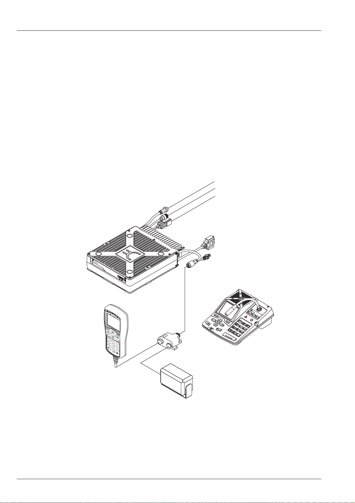
The Envoy™ Transceiver
Overview of the Envoy™ Transceiver
A typical Envoy™ Transceiver system comprises:
• a control point (2220 Handset, 2221 Handset, or 2230 Desk Console)
• a 2210 RFU
• a 12 V DC power supply
• an antenna system
Figure 1: Typical transceiver system
The transceiver is most easily programmed using Codan’s TPS system programmer,
however, the transceiver may be set up using the control point.
A range of options and accessories is available for the Envoy™ Transceiver. For more
information contact your Codan representative or refer to the product catalogue that
is applicable to your transceiver.
4 ENVOY™ TRANSCEIVER REFERENCE MANUAL
Page 27
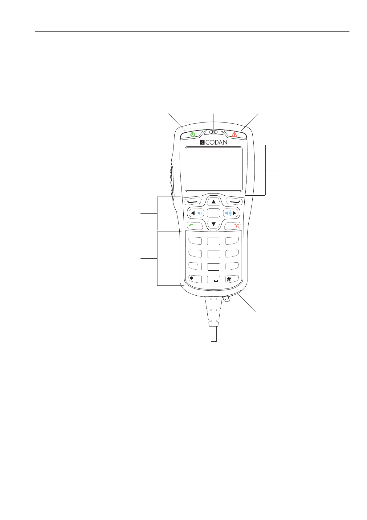
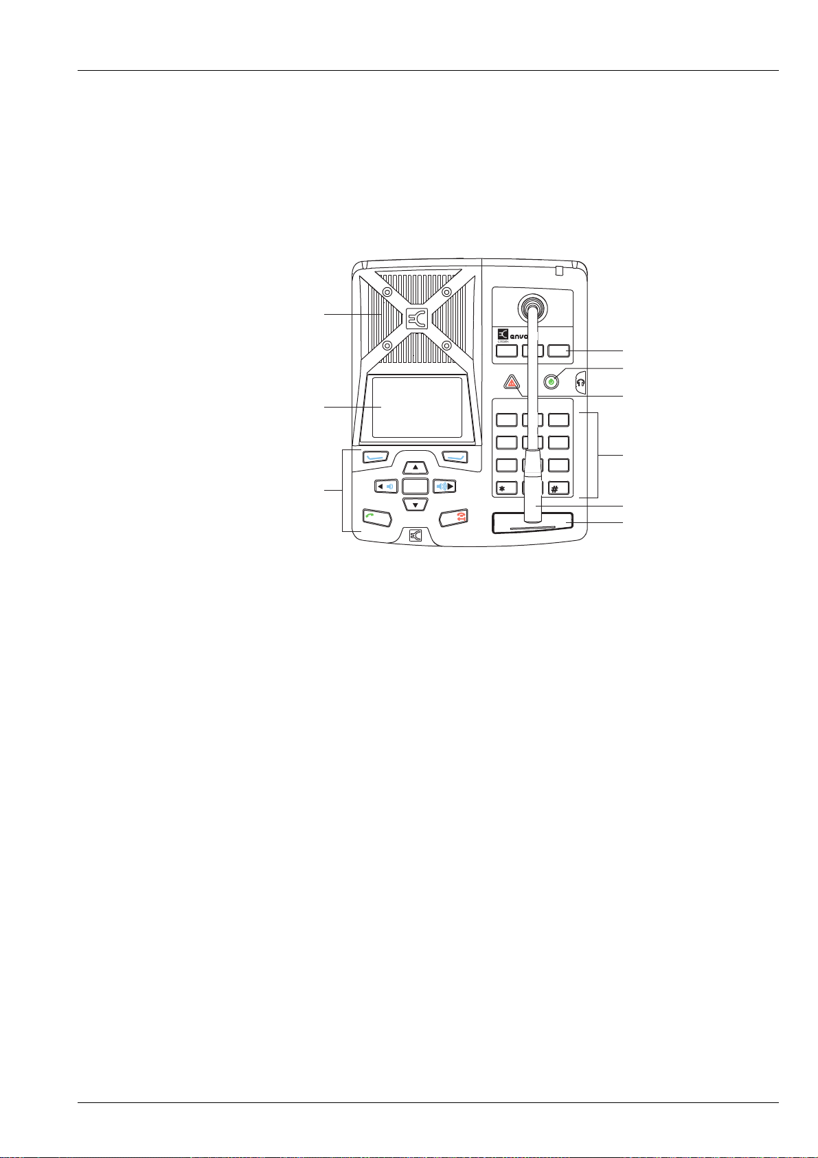
The 2220 Handset
navigation and
software keys
Power key Emergency key
numeric keys
USB connector
screen
microphone
CALL
SCAN
OK
1
TUNE
FUNC
MODE
FREE Rx
SEC
VS
VIEW
EASI
TALK
ABC
DEF
GHI
JKL
MNO
PQRS
TUV
WXYZ
2
3
4
5
6
7
8
9
0
PTT
The 2220 Handset is a control point for the Envoy™ Transceiver. The user interface
provides an icon-based menu structure for easy setup and operation of the transceiver.
Figure 2: 2220 Handset
INTRODUCTION
THE ENVOY™ TRANSCEIVER
The 2220 Handset is a hand-held device that has a microphone, a PTT button, a screen,
navigation keys, and numeric keys. The keypad enables you to control and configure
the transceiver system via the user interface. The handset and an external speaker
connect to the RFU via a special interface cable.
The 2220 Handset is shipped from the factory with standard functions
pre-programmed to specific keys. The standard function is written on the key in blue
text. New user-defined functions may be assigned to most of the keys.
Related links:
Navigating the menu structure on page 89
Keypad on page 265
ENVOY™ TRANSCEIVER REFERENCE MANUAL 5
Page 28
INTRODUCTION
CALL
SCAN
OK
navigation and
software keys
Power key Emergency key
USB connector
microphone
screen
PTT
THE ENVOY™ TRANSCEIVER
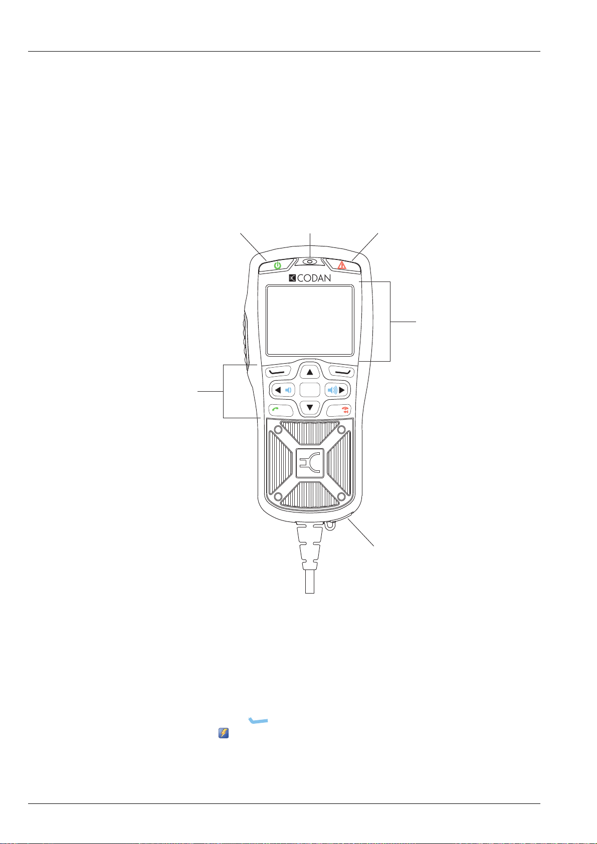
The 2221 Handset
The 2221 Handset is a control point for the Envoy™ Transceiver. The user interface
provides an icon-based menu structure for easy operation of the transceiver. It has a
condensed set of keys for use in simpler communication scenarios.
NOTE: This handset is recommended for operating the transceiver only.
Figure 3: 2221 Handset
Programming the transceiver should be completed via TPS.
The 2221 Handset is a hand-held device that has a microphone, a PTT button, a screen,
and navigation keys. The navigation keys enable you to operate the transceiver system
via the user interface using pre-defined profile information. Typically, this profile is
fully configured using the TPS system programmer. The handset and an external
speaker connect to the RFU via a special interface cable.
The 2221 Handset is shipped from the factory with specific functions
pre-programmed on the key, or in a general list that is accessed via the
Functions icon ( ). New user-defined functions may be assigned to this general list.
Related links:
Navigating the menu structure on page 89
6 ENVOY™ TRANSCEIVER REFERENCE MANUAL
Page 29
The 2230 Desk Console
FUNC
ABC
2
Desk Console
F1
F2 F3
MODE
DEF
31
TUNE
FREE Rx
GHI
4
MNO
6
WXYZ
9
V/S
PQRS
7
EASI
TALK
VIEW
0
SEC
TUV
8
JKL
5
SCAN
CALL
OK
speaker
boom microphone
function keys
Power key
Emergency key
numeric keys
PTT
screen
navigation and
software keys
The 2230 Desk Console is a control point for the Envoy™ Transceiver. The user
interface provides an icon-based menu structure for easy setup and operation of the
transceiver. The desk console is standard for a fixed station.
Figure 4: 2230 Desk Console
INTRODUCTION
THE ENVOY™ TRANSCEIVER
The 2230 Desk Console has an optional boom microphone, a built-in speaker, a PTT
button, a screen, navigation keys, function keys, and numeric keys. The desk console
also supports the use of headphones, a foot-switched PTT device, and a separate hand
microphone with PTT. The keypad enables you to control and configure the
transceiver system via the user interface.
The 2230 Desk Console is shipped from the factory with standard hot keys
programmed to the numeric keys. The function that each standard hot key performs is
written on the numeric key in blue text. New user-defined functions may be assigned
to most of the keys.
Related links:
Navigating the menu structure on page 89
Keypad on page 265
ENVOY™ TRANSCEIVER REFERENCE MANUAL 7
Page 30

INTRODUCTION
THE ENVOY™ TRANSCEIVER
The 2210 RFU
The RFU modulates audio signals onto radio frequencies that can be transmitted on
air, and demodulates the radio frequencies it receives into audio signals. It also
interprets the instructions that you enter through the control point.
Figure 5: 2210 RFU
™
RF Unit
Serial No.
Type 2210
8 ENVOY™ TRANSCEIVER REFERENCE MANUAL
Page 31

2
Using the wizard
This section contains the following topics:
• Overview of the wizard on page 10
• Using the wizard on page 12
ENVOY™ TRANSCEIVER REFERENCE MANUAL 9
Page 32

USING THE WIZARD
OVERVIEW OF THE WIZARD
Overview of the wizard
The wizard is available if the transceiver:
• has not been programmed with a profile
• has a basic profile that has a common self address for each of the default HF
networks: Selcall and CALM
• has one scan table
The wizard steps you through setting up information in the transceiver so that it may
be operated at a basic level.
Figure 6: Steps in the wizard
10 ENVOY™ TRANSCEIVER REFERENCE MANUAL
Page 33

Related links:
The Envoy™ Transceiver on page 4
Navigating the menu structure on page 89
USING THE WIZARD
OVERVIEW OF THE WIZARD
ENVOY™ TRANSCEIVER REFERENCE MANUAL 11
Page 34

USING THE WIZARD
USING THE WIZARD
Using the wizard
The wizard should start automatically when a new transceiver is powered up for the
first time.
Figure 7: Wizard Startup screen
NOTE: If the wizard screen doesn’t launch automatically, follow the
instructions below. If your transceiver has been profiled using TPS, the
wizard may not be available.
To use the wizard:
1 Press PTT, then press (Menu) to return to the top level of the menu
structure.
1 Check that the icon for the wizard is highlighted ( ), then press (OK).
1 Press (Yes) to confirm that you want to start the wizard.
If you want to bypass the wizard, press (No).
12 ENVOY™ TRANSCEIVER REFERENCE MANUAL
Page 35

Selecting a language
NOTE: This step in the wizard is shown if you have multiple languages
To select a language:
1 Press or to scroll to the language that you want to use on the control point,
then press OK.
1 Press (Save) to save the information.
1 Press (Yes) to confirm that you want to change the language.
Related links:
Selecting a language on page 39
USING THE WIZARD
USING THE WIZARD
available.
Setting the time and date
To set the time and date:
1 Press or to select the time zone that you want to use.
1 Press to move to the Daylight Saving entry.
1 Press or to select the time that you want to use.
1 Press to move to the Local Time entry.
1 Press to enter edit mode for the local time.
1 Press or to scroll to the value that you want to set, then press to move to
the next item.
1 Repeat this for minutes, seconds and AM/PM values.
1 Press (Save) to save the local time.
1 Press to move to the Local Date entry.
1 Press to enter edit mode for the local date.
1 Press or to scroll to the value that you want to set, then press to move to
the next item.
1 Repeat this for the day/month and year, as required.
1 Press (Save) to save the local date.
1 Press to move to the Clock entry.
1 Press or to select the type of clock that you want to use.
1 Press to move to the Time Format entry.
1 Press or to select the format that you want to use.
1 Press to move to the Date Format entry.
ENVOY™ TRANSCEIVER REFERENCE MANUAL 13
Page 36

USING THE WIZARD
USING THE WIZARD
1 Press or to select the format that you want to use.
1 If you want to review the information that you have entered, press or to
move through the entries.
1 Press (Save) to save the information.
If you have not changed any of the time and date information, press
(Close).
Related links:
Setting the time and date on page 40
Setting the location of the desk console
NOTE: This step in the wizard is shown if your control point is a desk console.
To set the location of the desk console:
1 Press or to select the value that you want to use from the following:
• If the desk console is connected to the RFU using cable 08-07205-00x,
select Local.
• If the desk console is connected to the RFU using an Ethernet cable
(08-07215-001), select Remote.
CAUTION: You must set this value correctly to ensure that the desk console
switches off and on.
1 Press (Save) to save the information.
If you have not changed the location of the desk console, press (Close).
Related links:
Setting the location of the desk console on page 43
14 ENVOY™ TRANSCEIVER REFERENCE MANUAL
Page 37

Adding a channel
NOTE: This step in the wizard is shown if you are permitted to add channels.
To add a channel:
1 Press (Yes) to add a channel, if required.
1 Enter the name that you want to use for the channel.
1 Press to move to the Tx entry.
1 Enter the transmit frequency that you want to use for this channel (in kHz, with
1 Press to move to the Rx entry.
1 Enter the receive frequency (in kHz, with up to three decimal points or 1 Hz
USING THE WIZARD
USING THE WIZARD
up to three decimal points or 1 Hz resolution).
The Rx entry is automatically filled with the transmit frequency.
resolution), if required to be different from the Tx frequency.
1 Press to move to the Mode entry.
1 To select a mode:
• Press to view the list of available modes.
• Press or to scroll to the mode that you want to use, then press OK.
When the check box is selected, the item is enabled. When the check box
is clear, the item is disabled.
• Select other modes, as required.
NOTE: The modes that you select become the allowed modes for
this channel. In a scan table, you can duplicate a channel
and select another of the allowed modes.
•Press (Save).
1 If you want to review the information that you have entered, press or to
move through the entries.
1 Press (Save) to save the information.
1 Do one of the following:
• If you want to add another channel, press (Yes), then repeat these
steps.
• If you do not want to add another channel, press (No).
The channels that you enter may be notionally grouped into a scan table. A scan
table enables you to manage how these channels are scanned using one set of
properties.
ENVOY™ TRANSCEIVER REFERENCE MANUAL 15
Page 38

USING THE WIZARD
USING THE WIZARD
1 Do one of the following:
• If you want to add a scan table, press (Yes).
• If you do not want to add a scan table, press (No), then continue from
Entering a self address on page 16.
1 Do one of the following:
• If you want to scan all of the channels in the transceiver that have a USB
mode, press (Yes), then continue from Entering a self address on
page 16.
• If you want to choose the channels and modes that you want to scan,
press (No), then continue from Adding channels to a scan table on
page 16.
Related links:
Overview of scan tables on page 128
Overview of HF networks on page 140
Adding a channel on page 123
Adding channels to a scan table
To add channels to a scan table:
1 Press or to scroll to the channel that you want to add, then press OK.
1 Press or to select the mode that you want to use.
1 Select more channels, as required.
1 Press (Save) to add these channel selections.
1 Continue from Entering a self address on page 16.
Entering a self address
A self address is used by other stations to call your station. For example, if the self
address of your station is 1234, operators at other stations enter the address 1234 when
they want to make a call to you.
To enter a self address:
1 Enter the address that you want to use.
You can enter up to six digits.
NOTE: Addresses ending in 99 and 00 have a special function in Selcall
HF networks.
1 Press (Save) to save the information.
16 ENVOY™ TRANSCEIVER REFERENCE MANUAL
Page 39

1 Do one of the following:
Adding a contact
A contact is a person or organisation that you want to call, and for which you want to
pre-define the method of calling. You may be able to contact the same person or
organisation via a number of different methods. When you set up the contact, you
define each method as a separate call for the contact.
USING THE WIZARD
USING THE WIZARD
NOTE: The wizard automatically allocates this self address to the default
HF networks: Selcall and CALM (if FED-STD-1045 ALE or
MIL-STD-188-141B ALE option is installed).
• If you want to add a contact, press (Yes), then continue from Adding
a contact on page 17.
• If you do not want to add a contact, press (No), then continue from
Selecting an antenna on page 20.
NOTE: If you require more detail on adding a contact, see Contacts on
page 157.
To add a contact:
1 Enter the name that you want to use for the contact, then press (Add Call).
The HF Network entry is highlighted.
The HF network defines the call system and self address that is used by your
station when the call is made. For example, if you are using a Selcall HF
network, you must select a channel for the call. If you are using a CALM HF
network, you may either select a channel or let the transceiver select a channel
for the call.
1 Press or to select the HF network that you want to use.
1 Press to move to the Call Type entry.
1 Press or to select the call type that you want to use.
NOTE: The call type that you select affects information that you can
enter for the remainder of this call.
1 If you are adding:
• a Selective, Channel Test, Emergency, Get Position or Send Position call,
continue from Adding a simple call on page 18
• a Message call, continue from Adding a Message call on page 18
• a Phone call, continue from Adding a Phone call on page 19
Related links:
Call types on page 434
ENVOY™ TRANSCEIVER REFERENCE MANUAL 17
Page 40

USING THE WIZARD
USING THE WIZARD
Adding a simple call
A simple call is a call that requires an address only at this stage of the definition
process.
To continue with adding a Selective, Channel Test, Emergency, Get Position or Send
Position call:
1 Press to move to the Selcall|ALE Address entry.
1 Enter the address of the station that you want to call.
1 Continue from Completing the contact on page 20.
Adding a Message call
To continue with adding a Message call:
1 Press to move to the Selcall|ALE Address entry.
1 Enter the address of the station that you want to call.
1 Press to move to the Message entry, then press .
NOTE: If you want to be prompted to enter a message at the time of the
call, leave the value for the Message entry as <Empty>.
18 ENVOY™ TRANSCEIVER REFERENCE MANUAL
Page 41

USING THE WIZARD
USING THE WIZARD
1 If you want to enter a message:
• Start typing the message.
NOTE: Press OK to start a new line, if required.
•Press (Options), scroll to Save, then press (Select) to add the
message to the call.
1 If you want to select a message from a list of stored messages:
•Press (Options), scroll to Stored, then press (Select).
• Press or to scroll to the message that you want to use.
NOTE: If you want to view the message, press (Details) to
view the message, then press (Close).
•PressOK to select the message.
• Edit the message, if required.
•Press (Options), scroll to Save, then press (Select).
1 Continue from Completing the contact on page 20.
Adding a Phone call
To continue with adding a Phone call:
1 Press to move to the Phone Number entry.
1 Enter the phone number.
1 Continue from Completing the contact on page 20.
ENVOY™ TRANSCEIVER REFERENCE MANUAL 19
Page 42

USING THE WIZARD
USING THE WIZARD
Completing the contact
To finish entering the information required for the contact:
1 Press to move to the Call Description entry.
The call type is entered automatically as the call description.
1 Enter a new description for this call, if required.
1 Press (Save) to save the information.
1 If you want to add another call for the contact, press (Yes), then repeat the
steps for adding a call.
If you do not want to add another call, press (No).
1 If you want to add another contact, press (Yes), then repeat the steps for
adding a contact.
If you do not want to add another contact, press (No).
1 Do one of the following:
• If you want to select an antenna, continue from Selecting an antenna on
• If you do not want to select an antenna, press (Close), then continue
Related links:
Adding a contact on page 17
Selecting an antenna
Each type of antenna has a specific requirement for tuning, and the transceiver uses a
different protocol for each one. You must select the type of antenna that is used in your
station so that the transceiver knows how to tune the antenna. Some antennas, such as
broadband antennas, do not require tuning.
To select an antenna:
page 20.
from Selecting a peripheral device on page 21.
1 Press or to scroll to the antenna type that you want to use, then press OK.
1 Press (Save) to save the information.
1 Do one of the following:
• If you want to connect an accessory to the 15-way connector of the RFU,
press (Yes), then continue from Selecting a peripheral device on
page 21.
• If you do not want to connect an accessory, press (No), then
press OK to close the wizard.
20 ENVOY™ TRANSCEIVER REFERENCE MANUAL
Page 43

Selecting a peripheral device
When you select the peripheral device from the list, the transceiver automatically sets
these properties.
NOTE: Codan peripheral devices are listed by their type number, for example,
3031 Crosspatch. The type number for a Codan device is located on the
front or serial number escutcheon.
To select a peripheral device:
1 Press or to scroll to the type of peripheral device that is attached to the
connector, then press OK.
If there are settings that you can change to optimise this peripheral for your
requirements, is shown to the right of the peripheral name when it is selected.
1 If you want to change settings for the peripheral, press to see the list of entries
that you may change.
USING THE WIZARD
USING THE WIZARD
If the value of an entry for a peripheral device has been changed from the default
value, is shown next to the title of the entry.
1 Press (Save) to automatically update settings for correct operation of the
connected peripheral device.
1 Press OK to close the wizard.
1 If you added a peripheral device, restart your transceiver to activate the new
settings.
ENVOY™ TRANSCEIVER REFERENCE MANUAL 21
Page 44

USING THE WIZARD
USING THE WIZARD
This page has been left blank intentionally.
22 ENVOY™ TRANSCEIVER REFERENCE MANUAL
Page 45

Operating the
3
transceiver
This section contains the following topics:
• Switching the transceiver on and off on page 24
• The channel screen on page 25
• Scanning channels on page 33
• Muting the transceiver on page 35
• Using the microphone on page 37
• Manually tuning the antenna on page 38
• Selecting a language on page 39
• Setting the time and date on page 40
• Setting the brightness of the display on page 41
• Setting the display timeout on page 42
• Setting the location of the desk console on page 43
• Calling on page 45
• Using the clarifier on page 67
• Reducing background noise with Easitalk™ on page 68
• Viewing information about your transceiver on page 69
• Using GPS on page 73
• Using encryption on page 77
• Using a crosspatch on page 82
• Upgrading the transceiver via a USB stick on page 84
• Entering a password for an option on page 85
• Performing a self-test on page 86
• Finding an RFU on page 87
ENVOY™ TRANSCEIVER REFERENCE MANUAL 23
Page 46

OPERATING THE TRANSCEIVER
SWITCHING THE TRANSCEIVER ON AND OFF
Switching the transceiver on and off
Switching on the transceiver
To switch on the transceiver:
1 Press .
The template screen, then the welcome screen (if set) are shown briefly,
followed by the channel screen.
Switching off the transceiver
To switch off the transceiver:
1 Do one of the following:
• Hold for 2 sec, then release.
• Press , then press OK.
The transceiver is switched off.
24 ENVOY™ TRANSCEIVER REFERENCE MANUAL
Page 47

The channel screen
channel name
Tx/Rx frequency
status areas
menu bar
title bar
mode
mute type
indicator
(highlighted
when mute is on)
call type
icon
Tx power
setting
signal
strength
indicator
Rx/Tx
indicator
left
software
key
right
software
key
volume
indicator
The channel screen shows the following information:
• the name of the currently selected channel
• the transmit and receive frequencies, if applicable
• the status areas that show specific information about the transceiver
• a bar graph that indicates the signal strength on receive (green) and the output
power on transmit (red)
• the transmit power level setting
• the call type icon (when calling) or the scan indicator (when scanning)
• the mute type indicator
• the mode
OPERATING THE TRANSCEIVER
THE CHANNEL SCREEN
• the crosspatch indicator, if connected
• the clarifier indicator, if set
Figure 8: Channel screen
NOTE: If you cannot transmit on the channel, Inhibit is shown as the Tx
frequency.
If the transmit and receive frequencies are the same, the frequency is only shown on
the right side of the screen. The Rx/Tx indicator shows whether the transceiver is
receiving (green) or transmitting (red). The more bars that are shown, the higher the
signal strength.
ENVOY™ TRANSCEIVER REFERENCE MANUAL 25
Page 48

OPERATING THE TRANSCEIVER
THE CHANNEL SCREEN
The status area of the screen provides six separate areas in which you can show
information that is relevant for your operations. Your system administrator can choose
the information that is shown in each status area. If encryptor/scrambler options are
enabled, this information is shown in the top line of the status area.
Your transceiver may have the option of selecting high, medium, or low power. Hi,
Med, or Lo is shown respectively to the right of the signal strength indicator. If an
external power amplifier is connected, PA may also be selected.
While a call is being established, the transceiver shows that calling activity is in
progress by flashing in place of the scan indicator. Once a call is established, these
indicators are replaced with an icon that represents the type of call being sent or
received.
When the transceiver is scanning, the channel screen is replaced by the scanning
screen.
Figure 9: Scanning screen
scan indicator
Related links:
Call types on page 434
Selecting information to be shown in a status area on page 28
Overview of the 3031 Crosspatch on page 82
Using the clarifier on page 67
26 ENVOY™ TRANSCEIVER REFERENCE MANUAL
Page 49

Selecting a channel
To select a channel:
1 Press PTT to exit to the channel or scanning screen.
1 If the transceiver is scanning, press SCAN to switch off scanning.
1 Press or to scroll to the channel that you want to use.
OPERATING THE TRANSCEIVER
THE CHANNEL SCREEN
The channel is selected.
NOTE: If you want to change the sideband, press MODE. If the mode
does not change, there is only one mode for the channel.
NOTE: If you have an automatic antenna tuner fitted, press PTT to tune
the antenna to the currently selected channel.
1 Do any of the following:
• Hold OK to edit the channel, if permitted.
•PressOK to search for a channel.
•PressCALL to start a call.
• Hold CALL to go to Contacts.
Related links:
Finding a word or value on page 99
Call Key Options on page 207
ENVOY™ TRANSCEIVER REFERENCE MANUAL 27
Page 50

OPERATING THE TRANSCEIVER
status area 1 status area 2
status area 3
status area 5 status area 6
status area 4
THE CHANNEL SCREEN
Selecting information to be shown in a status area
There are six status areas on the channel screen, scanning screen, and free-tune screen
that provide operational information directly to the user.
Figure 10: Status areas
NOTE: Information in status areas 1 and 2 is replaced by the secure status when
a voice or data encryptor is available.
To select information to be shown in a status area:
1 From the main menu, select (Settings), then (Control Point).
1 Press or to select the Status Area tab.
1 Press or to scroll to the status area in which you want to show status
information.
1 Press or to select the status information that you want to show.
Table 1: Information that may be shown in the status areas on the screen
Item Description
Empty Status area is blank
Transceiver type Read from the template in the transceiver, for example, Envoy X1 or
Envoy X2
User-defined text 1/2 Any text that you want to show on the screen
28 ENVOY™ TRANSCEIVER REFERENCE MANUAL
Page 51
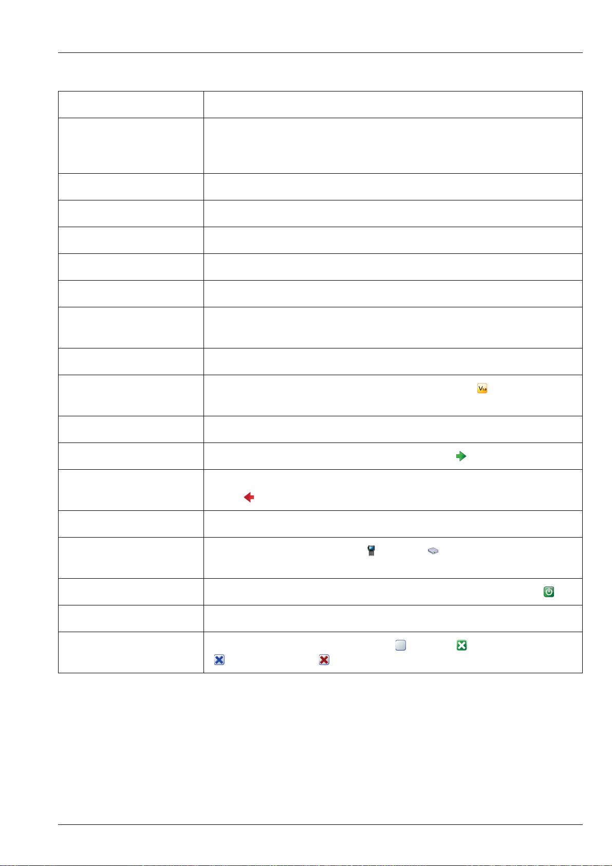
OPERATING THE TRANSCEIVER
THE CHANNEL SCREEN
Table 1: Information that may be shown in the status areas on the screen (cont.)
Item Description
Altitude,
Derived from GPS signals from a GPS receiver
Latitude/Northing,
Longitude/Easting, Speed
PA temperature Temperature of the heatsink
Tx power Monitored transmit power from the transceiver
Rx level Strength of an incoming signal shown in dBμV
Voltage Battery voltage
Last received call Who and when details of the last call received
SWR The ratio of forward to reflected power of the antenna during transmit
(typical range 1:1.0 to 1:1.8, which is only valid on the current channel)
Date, Time, Time Zone Current date, time and time zone of the control point
Package version, Package
Details of the firmware in the control point and RFU ( )
build date
Primary self address Self address of the first-listed HF network in your transceiver
Last received address Contact name or address of the last call received ( )
Last sent self address Self address of your transceiver that was sent with the last call that you
made ( )
Profile name Name of the TPS profile programmed into the transceiver
CP IP address, RFU IP
IP address of the control point ( ) or RFU ( )
address
Power down time Time at which the transceiver will power down, in 24-hour format (
Best LQA channel Future use
Crosspatch state Current crosspatch state may be Off ()|Active ()|Standby
()|Disconnected ()
ENVOY™ TRANSCEIVER REFERENCE MANUAL 29
Page 52

OPERATING THE TRANSCEIVER
THE CHANNEL SCREEN
Table 1: Information that may be shown in the status areas on the screen (cont.)
Item Description
2.4 kbit/s Data Modem
throughput
Grey LED, solid: modem is not in a link
Green LED, solid: modem is enabled and a computer is communicating
with it via VCOM
Green LED, flashing: modem is in a link and received the link
Red LED, flashing: modem is in a link and started the link
Red bar is indicative of the data throughput rate for the link
Zone (UTM) Zone, if UTM is selected in Settings > GPS > GPS Format Options
1 Press (Save) to save the information.
Related links:
Settings > Control Point > Status Area on page 212
30 ENVOY™ TRANSCEIVER REFERENCE MANUAL
Page 53

Selecting a theme
Menu screen Channel screen
Theme
Blue/Grey
(default
day time)
Grey/Red
Grey/Blue
Blue/Green
Dark Blue
(default
night time)
You can select one of the following themes for the display in the control point. You
can select one theme for use during the day, and another for use during the night.
Figure 11: Available themes for the display in the control point
OPERATING THE TRANSCEIVER
THE CHANNEL SCREEN
To select a theme:
1 From the main menu, select (Settings), then (Control Point).
1 Press or to scroll to the Theme or Night Theme entry.
1 Press or to select the theme that you want to use.
ENVOY™ TRANSCEIVER REFERENCE MANUAL 31
Page 54

OPERATING THE TRANSCEIVER
THE CHANNEL SCREEN
1 If you have set a night theme, do the following:
1 Press (Save) to save the information.
1 Switch the transceiver off then on again to activate the new theme.
• Press or to scroll to the Night Display Start entry.
• Press or to select the time that you want to start displaying the night
time theme.
• Press to move to the Night Display Stop entry.
• Press or to select the time that you want to start displaying the day
time theme.
32 ENVOY™ TRANSCEIVER REFERENCE MANUAL
Page 55

Scanning channels
If you intend to receive calls on several channels, switch on scanning. When scanning
is switched on, the transceiver sequentially selects each channel/mode in your scan
tables to detect incoming calls. The channels are scanned in a continuous cycle. By
default, mute is switched on automatically when scanning is switched on.
NOTE: Only those scan tables that are set to be scanned have the channels
scanned.
By default, when the transceiver detects a call addressed to your station, it stops
scanning and notifies you according to the type of call received. When you press
to end the call, scanning resumes. If you do not press this key to end the call, or any
other key within a pre-determined timeout, the transceiver automatically ends the call
and resumes scanning.
NOTE: The default standby state for the transceiver is to return to scanning so
that it is ready to receive calls across a range of frequencies.
OPERATING THE TRANSCEIVER
SCANNING CHANNELS
When the transceiver detects a signal, it notifies you according to the mute setting
selected. If your transceiver is set to notify you when voice is detected (V), you can
pause scanning, select the channel/mode on which the voice was heard, then resume
scanning when required. Voice mute also detects calls that are addressed to any station
on the scanned frequency, and any other channel disturbances. If your transceiver is
set to Selcall mute (S), it only pauses scanning when it detects a call addressed to your
station, regardless of the call system used.
Your choice of Voice or Selcall mute depends on whether or not you have to detect
voice signals, and how much noise and traffic you want to hear.
It is recommended that scanning is switched on when you are not using the transceiver
to communicate so that you are able to receive calls on any frequency in the scanned
scan tables.
Related links:
Adding a scan table on page 133
Call types on page 434
Muting the transceiver on page 35
Settings > Scan on page 228
ENVOY™ TRANSCEIVER REFERENCE MANUAL 33
Page 56

OPERATING THE TRANSCEIVER
SCANNING CHANNELS
Switching scanning on or off
To switch scanning on or off:
1 Press SCAN.
If a call is not in progress, scanning is toggled on or off.
If a call is in progress, the call is ended and the transceiver begins scanning.
If a call from a modem (or any other peripheral device) is in progress, you are
prompted to break the system lock to resume scanning.
NOTE: When scanning is switched on, mute is also switched on.
NOTE: If you press PTT while the transceiver is scanning, the scan is
stopped.
Pausing scanning
To pause scanning:
1 Do one of the following:
1 While scanning is paused, do one of the following:
• To pause scanning on the last-selected channel, press OK.
• To pause scanning and scroll to another channel, press or .
The channel/modes through which you can scroll are those in the scan tables
that are being scanned. They are not listed alphabetically but in the order in
which they are being scanned.
If you do not press a key within 30 sec, the transceiver automatically resumes
scanning.
• To speak on the selected channel, hold down PTT.
• To resume scanning immediately, press OK.
• To stop scanning completely, press SCAN.
34 ENVOY™ TRANSCEIVER REFERENCE MANUAL
Page 57

Muting the transceiver
When the transceiver is set to a channel or is scanning channels, and mute is switched
off, you hear on-air signals on each channel. If you do not want to listen to this, you
can silence the transceiver by switching on mute.
You can set the mute to switch off when a voice signal or any other calling activity is
detected (Voice mute V), or only when a call addressed to your station is received
(Selcall mute S). Your choice of Voice or Selcall mute depends on whether or not you
have to detect voice signals, and how much noise and traffic you want to hear. If you
have a digital voice encryptor fitted and active, you can also set the mute to switch off
only when a digitally encrypted voice signal is detected (Digital Voice mute D).
By default, mute automatically switches on when the transceiver starts scanning. The
transceiver listens for signals according to what is set in Settings > Scan Mute.
If the scan is paused due to voice being detected, the length of time that the transceiver
holds the pause with mute off is set in Settings > Scan Voice Max Pause and
Scan Voice Extend. Scanning only resumes automatically if the transceiver is set
to start scanning after a timeout period.
OPERATING THE TRANSCEIVER
MUTING THE TRANSCEIVER
Related links:
Scan Mute on page 229
Scan Voice Max Pause on page 229
Scan Voice Extend on page 229
Auto Resume Mode on page 228
Auto Resume Time on page 228
Switching mute on or off
To switch mute on or off:
1 If you are using a 2220 Handset or 2230 Desk Console, press (Mute) on
the channel screen, scanning screen, or free-tune screen.
1 If you are using a 2221 Handset:
•Press (Options).
• Press or to scroll to the Mute On|Off option.
•Press (Select).
The V or S in the title bar of the channel screen is highlighted when mute is on.
ENVOY™ TRANSCEIVER REFERENCE MANUAL 35
Page 58

OPERATING THE TRANSCEIVER
MUTING THE TRANSCEIVER
Selecting the mute type
To select the mute type:
1 If you are using a 2220 Handset or 2230 Desk Console, press V/S to toggle the
mute type between Selcall mute (S) and Voice mute (V).
1 If you are using a 2221 Handset:
•Press (Options).
• Press or to scroll to the V/S option.
•Press (Select).
NOTE: If you have the AES-256 digital voice encryptor fitted and active,
Related links:
Digital Voice mute on page 356
an additional mute type of Digital Voice mute (D) is available.
36 ENVOY™ TRANSCEIVER REFERENCE MANUAL
Page 59

Using the microphone
The microphone on the handset is located at the top between the and keys. When
you talk into the microphone:
• hold the microphone side-on and close to your mouth
• hold down PTT
• speak clearly at your normal volume and rate
• release PTT to return to receiving mode
On the desk console, you can speak directly into the boom microphone.
NOTE: By default, the transceiver is set up to transmit a short beep when you
release PTT. This removes the need for you to say ‘over’ at the end of
your transmission.
OPERATING THE TRANSCEIVER
USING THE MICROPHONE
CAUTION: Your conversation can be monitored by anyone tuned to your transmit
frequency, unless you are using one of Codan’s encryption options.
Your signal can potentially travel very large distances.
If PTT is held continuously for a certain length of time, the system stops transmission,
switches to receive and shows an error message on the control point. This ensures that,
even if the PTT button is being held down accidentally, the battery will not be
flattened, and your transceiver is ready to receive calls.
You can set the length of time the system waits before it cuts transmission (default is
10 min), or switch off this feature.
Related links:
Handset PTT Beep on page 223
PTT Timeout on page 223
Encryption on page 317
ENVOY™ TRANSCEIVER REFERENCE MANUAL 37
Page 60

OPERATING THE TRANSCEIVER
MANUALLY TUNING THE ANTENNA
Manually tuning the antenna
WARNING: Before using the antenna system see the safety information provided.
NOTE: If the transceiver is connected to an automatic tuning antenna, it tunes
the antenna automatically when required.
You may need to manually tune the antenna if you are receiving on a new channel, or
if you want to check the SWR value for the antenna.
To manually tune the antenna:
1 Press TUNE.
The SWR, battery voltage, and type of antenna tuner are shown on the screen.
1 Hold down PTT to start the tuning process.
The transceiver makes a series of short beeps.
An SWR of less than 2:1 is acceptable.
NOTE: If PTT is held for more than 2 minutes, tuning is automatically
aborted. The transceiver displays a message to inform you of
this, makes an error beep, and returns you to the screen from
which you began.
1 Release PTT to stop tuning.
The beeps cease and you are returned to the screen from which you began.
Related links:
Radiation safety (EU installations only) on page 470
Radiation safety (non-EU installations) on page 472
38 ENVOY™ TRANSCEIVER REFERENCE MANUAL
Page 61

Selecting a language
The default language for the control point is English, however, you may have other
language options available for the control point.
Figure 12: Select Language screen
OPERATING THE TRANSCEIVER
SELECTING A LANGUAGE
To select a language:
1 From the main menu, select (Select Language).
1 Press or to scroll to the language that you want to use on the control point,
then press OK.
1 Press (Save) to save the information.
1 Press (Yes) to confirm that you want to change the language.
ENVOY™ TRANSCEIVER REFERENCE MANUAL 39
Page 62

OPERATING THE TRANSCEIVER
SETTING THE TIME AND DATE
Setting the time and date
The transceiver is set to UTC time in the factory. You set the local time and time zone
for the location of the control point. This feature is useful if you have a communication
network that spreads over several time zones, or you need to time stamp your
transmissions according to the current time at longitude zero.
To set the time and date:
1 From the main menu, select (General), then (Time and Date).
1 Press (Set).
1 Press to move to the Time Zone entry.
1 Press or to select the time zone that you want to use.
1 Press to move to the Daylight Saving entry.
1 Press or to select the time that you want to use.
1 Press to move to the Local Time entry.
1 Press to enter edit mode for the local time.
1 Press or to scroll to the value that you want to set, then press to move to
the next item.
1 Repeat this for minutes, seconds and AM/PM values.
1 Press (Save) to save the local time.
1 Press to move to the Local Date entry.
1 Press to enter edit mode for the local date.
1 Press or to scroll to the value that you want to set, then press to move to
the next item.
1 Repeat this for the day/month and year, as required.
1 Press (Save) to save the local date.
1 Press to move to the Clock entry.
1 Press or to select the type of clock that you want to use.
1 Press to move to the Time Format entry.
1 Press or to select the format that you want to use.
1 Press to move to the Date Format entry.
1 Press or to select the format that you want to use.
1 If you want to review the information that you have entered, press or to
move through the entries.
1 Press (Save) to save the information.
40 ENVOY™ TRANSCEIVER REFERENCE MANUAL
Page 63

OPERATING THE TRANSCEIVER
SETTING THE BRIGHTNESS OF THE DISPLAY
Setting the brightness of the display
To set the brightness:
1 Do one of the following:
•Press + 0.
• From the main menu, select (General), then (Brightness).
1 Press or to scroll to the value that you want to set, then press OK.
1 Press (Save) to save the information.
ENVOY™ TRANSCEIVER REFERENCE MANUAL 41
Page 64

OPERATING THE TRANSCEIVER
SETTING THE DISPLAY TIMEOUT
Setting the display timeout
You can set the length of time that the display and keypad backlight remains on after
the last activity on the control point. After this time, the backlight value drops to Low.
When a key is pressed, the backlighting returns to the value set in the Brightness
entry.
To set the display timeout:
1 From the main menu, select (General), then (Brightness).
1 Press to move to the Set Auto Dim Time tab.
1 Press or to scroll to the value that you want to set, then press OK.
1 Press (Save) to save the information.
Related links:
Setting the brightness of the display on page 41
42 ENVOY™ TRANSCEIVER REFERENCE MANUAL
Page 65

OPERATING THE TRANSCEIVER
SETTING THE LOCATION OF THE DESK CONSOLE
Setting the location of the desk console
The desk console may be connected directly to the transceiver, or it may be connected
remotely.
Figure 13: Connection between RFU and desk console using 10-way to
8-way cable
antenna control
antenna
battery
™
RF Unit
RF unit
Serial No.
Type 2210
15-way
connector
connector
10-way
connector
08-07205-00x
desk console
6-way
8-way
connector
™
Desk Console
ENVOY™ TRANSCEIVER REFERENCE MANUAL 43
Page 66

OPERATING THE TRANSCEIVER
RF Unit
™
Type 2210
Serial No.
antenna control
antenna
battery
RF unit
10-way
connector
15-way
connector
6-way
connector
Desk Console
™
desk console
RJ45
connector
Ethernet switch/
router/network
(optional)
08-07215-001
(10-way to RJ45)
12 V DC source
(78-16019)
SETTING THE LOCATION OF THE DESK CONSOLE
Figure 14: Connection between RFU and desk console using Ethernet
cables and optional switch
NOTE: The Console tab is available if a desk console is detected as a control
point.
To set the location of the desk console:
1 From the main menu, select (Settings), then (Control Point).
1 Press or to select the Console tab.
1 Press to move to the Console Location entry.
1 Press or to select the value that you want to use from the following:
• If the desk console is connected to the RFU using cable 08-07205-00x,
• If the desk console is connected to the RFU using an Ethernet cable
CAUTION: You must set this value correctly to ensure that the desk console
select Local.
(08-07215-001), select Remote.
switches off and on.
1 Press (Save) to save the information.
Related links:
Console Location on page 217
44 ENVOY™ TRANSCEIVER REFERENCE MANUAL
Page 67

Calling
This section describes how to make the various types of calls from the transceiver.
You can make a call to a contact, return or repeat a call from the Call History, or enter
information at the time of the call.
Related links:
Making a call to a contact on page 45
Making a call from the Call History on page 46
Making a call from the Emergency key on page 47
General calling on page 48
Making a call to a contact
NOTE: The default behaviour for the CALL key is to press it to start a call, or
hold it to see your Contacts/Call History.
OPERATING THE TRANSCEIVER
CALLING
To make a call to a contact:
1 Hold CALL.
1 Press or to scroll to the contact who you want to call.
1 If required, press or to scroll to the call that you want to make.
The call types that are available for the contact are set up in User Data >
Contacts.
NOTE: If only one call has been set up for the contact, you cannot select
a different call type at the time of the call.
1 Press CALL.
NOTE: Depending upon the call type and other information stored with
the contact, you may be prompted to select information during
the call. Press CALL to progress through these prompts.
ENVOY™ TRANSCEIVER REFERENCE MANUAL 45
Page 68

OPERATING THE TRANSCEIVER
CALLING
1 If prompted, press or to scroll to the channel that you want to use, then
press CALL.
A is shown next to the currently selected channel/mode.
To abort the call before it is answered, press PTT or SCAN.
There will be audible beeps or a pop-up message to indicate that the call has
been successful.
Related links:
Adding a contact on page 163
Making a call from the Call History
The Envoy™ Transceiver stores information on the calls that you send and receive.
The detailed call history is accessed by holding CALL, then pressing to scroll to the
Call History tab.
NOTE: The default behaviour for the CALL key is to press it to start a call, or
hold it to see your Contacts/Call History.
NOTE: A filtered Call Log is available in the call screen. This log contains only
the latest instance of a call to and from a specific station.
To make a call from the Call History:
1 Hold CALL.
1 Press or to select the Call History tab.
1 Press or to scroll to the call that you want to return or repeat, then
press CALL.
1 If you want to view the details of the call, press (Options), scroll to
Details, then press (Select).
Press (Close) to exit from the call details.
1 Press CALL.
1 Press or to select the call type that you want to use.
1 Continue from making your chosen call type.
46 ENVOY™ TRANSCEIVER REFERENCE MANUAL
Page 69

Related links:
Call Key Options on page 207
Making a Selective call on page 48
Making a Channel Test call on page 50
Making a Message call on page 53
Making a Phone call on page 56
Making a Send Position call on page 57
Making a Get Position call on page 58
Making a Get Status call on page 60
Making an Emergency call on page 62
Making an RFDS Emergency call on page 63
Making a Marine Emergency call on page 64
Making an ALE Sounding call on page 65
Making a call from the Emergency key
OPERATING THE TRANSCEIVER
CALLING
You can set up an emergency contact with calls that are chained together when you
hold the key. Emergency contacts are set up in User Data > Contacts >
Emergency Contacts.
CAUTION: If you have more than one emergency contact, you will be prompted to
select the emergency contact that you want to call at the time of the call.
To make a call from the Emergency key:
1 Hold for 2 sec.
1 If you have more than one emergency contact, scroll to the contact who you
want to call, then press CALL.
1 If prompted, press or to scroll to the channel that you want to use, then
press CALL.
A is shown next to the currently selected channel/mode.
To abort the call before it is answered, press PTT or SCAN.
There will be audible beeps or a pop-up message to indicate that the call has
been successful.
Related links:
Overview of contacts on page 158
Adding a contact on page 163
Chain call on page 159
ENVOY™ TRANSCEIVER REFERENCE MANUAL 47
Page 70

OPERATING THE TRANSCEIVER
CALLING
General calling
Figure 15: Call screen with Call Log
navigation
indicator
incoming call
outgoing call
select HF network
call type HF network
Related links:
Making a Selective call on page 48
Making a Channel Test call on page 50
Making a Message call on page 53
Making a Phone call on page 56
Making a Send Position call on page 57
Making a Get Position call on page 58
Making a Get Status call on page 60
Making an Emergency call on page 62
Making an RFDS Emergency call on page 63
Making a Marine Emergency call on page 64
Making an ALE Sounding call on page 65
address
Making a Selective call
If you want to speak with the operator at a particular station, make a Selective call to
the address of that station. When the station receives the call, the transceiver sounds
an alert tone to notify the operator.
To make a selective call:
1 Press CALL.
The call type and address of the last call are shown at the top of the call screen.
The filtered call log below this shows the latest instance of any call type made
to or received from a particular address.
48 ENVOY™ TRANSCEIVER REFERENCE MANUAL
Page 71

OPERATING THE TRANSCEIVER
CALLING
1 If you do not want to use the HF network shown at the top right of the screen:
•Press (Options).
• Scroll to HF Networks, then press (Select).
• Scroll to the HF network that you want to use, then press OK.
1 Press or to select the Selective call type if it is not selected.
NOTE: If you want to test the quality of the channel before you make the
actual call, hold CALL first.
1 Do one of the following:
• To repeat the call to the last address used, press CALL.
• To call a different station, enter the address, then press CALL.
• To repeat or return a call from the Call Log, press to scroll to the call,
press or to select your required call type, then press CALL.
• To use an ALE address syntax in an ALE/CALM HF network, press
(View), scroll to ALE, press (Select), scroll to the syntax that you
want to use, then press CALL.
1 If prompted, press or to scroll to the channel that you want to use, then
press CALL.
A is shown next to the currently selected channel/mode.
To abort the call before it is answered, press PTT or SCAN.
There will be audible beeps or a pop-up message to indicate that the call has
been successful.
Related links:
Selective call on page 440
Entering text in a field on page 103
Using multiple addresses for calls in an ALE/CALM HF network on page 453
Group calls in a Codan Selcall HF network on page 452
ENVOY™ TRANSCEIVER REFERENCE MANUAL 49
Page 72

OPERATING THE TRANSCEIVER
CALLING
Making a Channel Test call
A Channel Test call enables you to test the quality of a channel/mode in a Codan
Selcall HF network, and is sometimes referred to as a Beacon call. If you have the
MIL-STD-188-141B ALE option installed, a Channel Test call may be made in an
ALE/CALM HF network to replace information in the LQA database, and to perform
a manual sounding operation.
There are two ways to test the quality of a channel/mode in a Codan Selcall HF
network. You can test the channel before you make the call, or you can start to make
the call and then test the channel prior to connecting.
Making a Channel Test call in a Selcall HF network
If you want to test the suitability of a channel/mode before you use it to transmit voice
or data, make a Channel Test call to a specific station. The quality is determined by
the strength and clarity of a revertive signal.
NOTE: If you set up one of the status areas to show the Rx level, you can view
the strength of the revertive signal.
To make a Channel Test call in a Selcall HF network:
1 Press CALL.
The call type and address of the last call are shown at the top of the call screen.
The filtered call log below this shows the latest instance of any call type made
to or received from a particular address.
1 If you do not want to use the HF network shown at the top right of the screen:
•Press (Options).
• Scroll to HF Networks, then press (Select).
• Scroll to the HF network that you want to use, then press OK.
1 Press or to select the Channel Test call type if it is not selected.
50 ENVOY™ TRANSCEIVER REFERENCE MANUAL
Page 73

OPERATING THE TRANSCEIVER
CALLING
1 Do one of the following:
• To repeat the call to the last address used, press CALL.
• To call a different station, enter the address, then press CALL.
• To repeat or return a call from the Call Log, press to scroll to the call,
press or to select your required call type, then press CALL.
1 If prompted, press or to scroll to the channel that you want to test, then
press CALL.
A is shown next to the currently selected channel/mode.
1 Listen for the revertive signal from the other station.
The volume and clarity of the signal indicates the quality of the channel/mode.
Related links:
Channel Test call on page 435
Entering text in a field on page 103
Selecting information to be shown in a status area on page 28
Making a Channel Test call as part of a call in a Selcall HF network
If you want to test the suitability of a channel/mode for transmitting voice or data
during a call, you can make a Channel Test call within the call that you are making.
NOTE: If you set up one of the status areas to show the Rx level, you can view
the strength of the revertive signal.
To test a channel as part of a call in a Selcall HF network:
1 Start the call that you want to make to the other station.
1 When you are prompted to select a channel for the call, scroll to the channel that
you want to use, then hold CALL to perform the Channel Test call.
1 Listen for the revertive signal from the other station.
The volume and clarity of the signal indicates the quality of the channel/mode.
1 Do one of the following:
• If the channel is suitable, press CALL.
• If you want to test another channel, scroll to the channel, then hold CALL.
ENVOY™ TRANSCEIVER REFERENCE MANUAL 51
Page 74

OPERATING THE TRANSCEIVER
CALLING
Related links:
Making a Channel Test call in an ALE/CALM HF network
NOTE: A Channel Test call in an ALE/CALM HF network is available if the
If you want to update the information stored in the LQA database for the called
address using the same HF network for the current time slot, make a Channel Test call
to this station. The calling station sends a beacon on each channel in the scan tables
associated with the HF network. Local and remote BER and SINAD information is
recorded, and an LQA score is determined for each channel.
To make a Channel Test call in an ALE/CALM HF network:
Channel Test call on page 435
Entering text in a field on page 103
Selecting information to be shown in a status area on page 28
MIL-STD-188-141B ALE option is installed.
1 Press CALL.
The call type and address of the last call are shown at the top of the call screen.
The filtered call log below this shows the latest instance of any call type made
to or received from a particular address.
1 If you do not want to use the HF network shown at the top right of the screen:
•Press (Options).
• Scroll to HF Networks, then press (Select).
• Scroll to the HF network that you want to use, then press OK.
1 Press or to select the Channel Test call type if it is not selected.
1 Do one of the following:
• To repeat the call to the last address used, press CALL.
• To call a different station, enter the address, then press CALL.
• To repeat or return a call from the Call Log, press to scroll to the call,
press or to select your required call type, then press CALL.
52 ENVOY™ TRANSCEIVER REFERENCE MANUAL
Page 75

OPERATING THE TRANSCEIVER
The LQA score for each channel is shown.
NOTE: If you switch to advanced view, BER/SINAD information is
displayed in the LQA screen.
1 Do one of the following:
•PressCALL to start a call to this station using the best channel.
• Press or to scroll to the channel that you want to use, then
press CALL.
CALLING
•Press (Close) to exit the LQA screen.
1 If you are continuing with a call, press or to select your required call type,
then press CALL.
Related links:
Channel Test call on page 435
Using multiple addresses for calls in an ALE/CALM HF network on page 453
Group Selective call on page 444
NET call on page 445
Entering text in a field on page 103
Making a Message call
If you want to send a text message to another station, make a Message call.
You can:
• enter a message at the time that you make a call
• store up to 10 messages in User Data > Messages for later use
• store messages in a contact as part of a pre-programmed Message call
To make a Message call:
1 Press CALL.
The call type and address of the last call are shown at the top of the call screen.
The filtered call log below this shows the latest instance of any call type made
to or received from a particular address.
ENVOY™ TRANSCEIVER REFERENCE MANUAL 53
Page 76
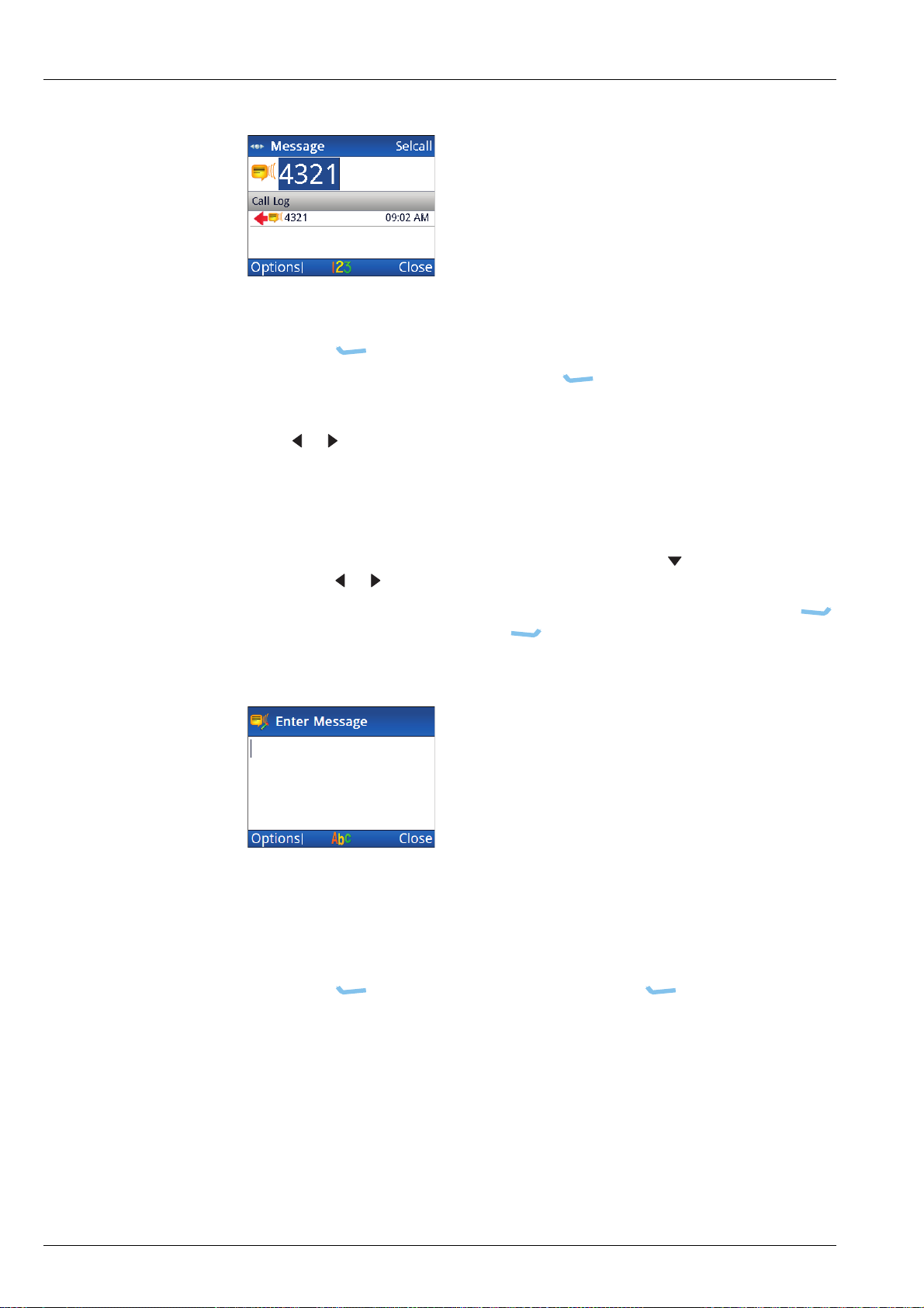
OPERATING THE TRANSCEIVER
CALLING
1 If you do not want to use the HF network shown at the top right of the screen:
1 Press or to select the Message call type if it is not selected.
1 Do one of the following:
•Press (Options).
• Scroll to HF Networks, then press (Select).
• Scroll to the HF network that you want to use, then press OK.
• To repeat the call to the last address used, press CALL.
• To call a different station, enter the address, then press CALL.
• To repeat or return a call from the Call Log, press to scroll to the call,
press or to select your required call type, then press CALL.
• To use an ALE address syntax in an ALE/CALM HF network, press
(View), scroll to ALE, press (Select), scroll to the syntax that you
want to use, then press CALL.
1 If you want to enter a message:
• Start typing the message.
NOTE: Press OK to start a new line, if required.
•Press (Options), scroll to OK, then press (Select) to add the
message to the call.
54 ENVOY™ TRANSCEIVER REFERENCE MANUAL
Page 77

OPERATING THE TRANSCEIVER
1 If you want to select a message from a list of stored messages:
•Press (Options), scroll to Stored, then press (Select).
• Press or to scroll to the message that you want to use.
NOTE: If you want to view the message, press (Details) to
view the message, then press (Close).
•PressOK to select the message.
• Edit the message, if required.
CALLING
•Press (Options), scroll to OK, then press (Select).
1 If prompted, press or to scroll to the channel that you want to use, then
press CALL.
A is shown next to the currently selected channel/mode.
To abort the call before it is answered, press PTT or SCAN.
There will be audible beeps or a pop-up message to indicate that the call has
been successful.
Related links:
Message call on page 438
Entering text in a field on page 103
Using multiple addresses for calls in an ALE/CALM HF network on page 453
Group calls in a Codan Selcall HF network on page 452
ENVOY™ TRANSCEIVER REFERENCE MANUAL 55
Page 78

OPERATING THE TRANSCEIVER
CALLING
Making a Phone call
If you want to speak with an operator on a phone line, make a Phone call to that
number. The transceiver makes an HF call to a telephone station (phone link), which
connects through to the public telephone network.
To make a Phone call:
1 Press CALL.
The call type and address of the last call are shown at the top of the call screen.
The filtered call log below this shows the latest instance of any call type made
to or received from a particular address.
1 Press or to select the Phone call type if it is not selected.
1 Do one of the following:
• Enter the phone number that you want to call, then press CALL.
• To repeat or return a call from the Call Log, press to scroll to the call,
press or to select your required call type, then press CALL.
1 If you are prompted to add a phone link, do the following:
• Enter the name that you want to use for the phone link.
• Press to move to the HF Network entry.
• Press or to select the HF network that you want to use.
• Press to move to the Selcall|ALE Address entry.
• Enter the address of the telephone station.
•Press (Save).
1 If you are prompted to select a phone link, scroll to the phone link that you want
to use, then press CALL.
1 If prompted, press or to scroll to the channel that you want to use, then
press CALL.
A is shown next to the currently selected channel/mode.
To abort the call before it is answered, press PTT or SCAN.
There will be audible beeps or a pop-up message to indicate that the call has
been successful.
1 Press SCAN, then press (Hangup) to end the call.
56 ENVOY™ TRANSCEIVER REFERENCE MANUAL
Page 79

Related links:
Phone call on page 440
Entering text in a field on page 103
Using multiple addresses for calls in an ALE/CALM HF network on page 453
Group calls in a Codan Selcall HF network on page 452
Making a Send Position call
If you want to send your GPS information to another station, make a Send Position
call.
NOTE: You can make a Send Position call if the GPS Call option is installed,
and your GPS information is valid. The transceiver sends GPS
information if you have a GPS receiver connected and configured, or
from valid content in Settings > GPS > My Position.
NOTE: When GPS information is sent via a Selcall HF network, the altitude is
shown as --.
OPERATING THE TRANSCEIVER
CALLING
To make a Send Position call:
1 Press CALL.
The call type and address of the last call are shown at the top of the call screen.
The filtered call log below this shows the latest instance of any call type made
to or received from a particular address.
1 If you do not want to use the HF network shown at the top right of the screen:
•Press (Options).
• Scroll to HF Networks, then press (Select).
• Scroll to the HF network that you want to use, then press OK.
1 Press or to select the Send Position call type if it is not selected.
ENVOY™ TRANSCEIVER REFERENCE MANUAL 57
Page 80

OPERATING THE TRANSCEIVER
CALLING
1 Do one of the following:
1 If prompted, press or to scroll to the channel that you want to use, then
• To repeat the call to the last address used, press CALL.
• To call a different station, enter the address, then press CALL.
• To repeat or return a call from the Call Log, press to scroll to the call,
press or to select your required call type, then press CALL.
• To use an ALE address syntax in an ALE/CALM HF network, press
(View), scroll to ALE, press (Select), scroll to the syntax that you
want to use, then press CALL.
press CALL.
A is shown next to the currently selected channel/mode.
To abort the call before it is answered, press PTT or SCAN.
There will be audible beeps or a pop-up message to indicate that the call has
been successful.
Related links:
Send Position call on page 441
Entering text in a field on page 103
My Position on page 252
Using multiple addresses for calls in an ALE/CALM HF network on page 453
Group calls in a Codan Selcall HF network on page 452
GPS Show Options on page 250
Making a Get Position call
If you want to obtain the GPS position of a specific station that has valid GPS
information, make a Get Position call to that station. Get Position calls are
automatically answered by the receiving station so an operator is not required to
process the return call.
NOTE: You can make a Get Position call if the GPS Call option is installed in
your transceiver and the transceiver that you are calling. The success
of your Get Position call depends upon the value set in Calling >
General > Respond GPS of the transceiver you are calling and the
privacy mode of the HF network that you are using for the call.
NOTE: When GPS information is sent via a Selcall HF network, the altitude is
shown as --.
To make a Get Position call:
1 Press CALL.
The call type and address of the last call are shown at the top of the call screen.
The filtered call log below this shows the latest instance of any call type made
to or received from a particular address.
58 ENVOY™ TRANSCEIVER REFERENCE MANUAL
Page 81

OPERATING THE TRANSCEIVER
CALLING
1 If you do not want to use the HF network shown at the top right of the screen:
•Press (Options).
• Scroll to HF Networks, then press (Select).
• Scroll to the HF network that you want to use, then press OK.
1 Press or to select the Get Position call type if it is not selected.
1 Do one of the following:
• To repeat the call to the last address used, press CALL.
• To call a different station, enter the address, then press CALL.
• To repeat or return a call from the Call Log, press to scroll to the call,
press or to select your required call type, then press CALL.
1 If prompted, press or to scroll to the channel that you want to use, then
press CALL.
A is shown next to the currently selected channel/mode.
To abort the call before it is answered, press PTT or SCAN.
There will be audible beeps or a pop-up message to indicate that the call has
been successful.
NOTE: The format of GPS information in call pop-ups is DDMM.SSSS S,
DDDMM.SSSS E, for example, 3452.8232 S, 13841.2614 E.
Related links:
Get Position call on page 437
Entering text in a field on page 103
Respond GPS on page 236
Privacy mode on page 145
GPS Show Options on page 250
ENVOY™ TRANSCEIVER REFERENCE MANUAL 59
Page 82

OPERATING THE TRANSCEIVER
CALLING
Making a Get Status call
If you want to obtain information on the status of a transceiver at a specific station,
such as the power output of the transmitter or the firmware versions installed, make a
Get Status call to that station. Get Status calls are automatically answered by the
receiving station so an operator is not required to process the return call.
NOTE: The success of your Get Status call depends upon the value set in
To make a Get Status call:
1 Press CALL.
Calling > General > Respond OTA of the transceiver you are
calling and the privacy mode of the HF network that you are using for
the call.
The call type and address of the last call are shown at the top of the call screen.
The filtered call log below this shows the latest instance of any call type made
to or received from a particular address.
1 If you do not want to use the HF network shown at the top right of the screen:
•Press (Options).
• Scroll to HF Networks, then press (Select).
• Scroll to the HF network that you want to use, then press OK.
1 Press or to select the Get Status call type if it is not selected.
1 Do one of the following:
• To repeat the call to the last address used, press CALL.
• To call a different station, enter the address, then press CALL.
• To repeat or return a call from the Call Log, press to scroll to the call,
press or to select your required call type, then press CALL.
60 ENVOY™ TRANSCEIVER REFERENCE MANUAL
Page 83

OPERATING THE TRANSCEIVER
CALLING
Figure 16: Available status types for a Get Status call in a Selcall or an
ALE/CALM HF network
Selcall HF network ALE/CALM HF network
MIL-STD-188-141B ALE option
ALE Site Manager:
Auto
Manual
Restricted
1 Press or to scroll to the status type that you want to use, then press OK.
1 If you selected ?: Other as the status type, enter the text/command that you
want to send (Options), scroll to OK (Select).
NOTE: For information on over-the-air commands, please contact your
Codan representative.
1 If prompted, press or to scroll to the channel that you want to use, then
press CALL.
A is shown next to the currently selected channel/mode.
To abort the call before it is answered, press PTT or SCAN.
There will be audible beeps or a pop-up message to indicate that the call has
been successful.
Related links:
Get Status call on page 437
ALE Site Manager on page 240
MIL-STD-188-141B ALE on page 143
Entering text in a field on page 103
Respond OTA on page 237
ENVOY™ TRANSCEIVER REFERENCE MANUAL 61
Page 84

OPERATING THE TRANSCEIVER
CALLING
Making an Emergency call
If you want to trigger an emergency alert tone at a particular station and speak with an
operator, make an Emergency call. If the GPS Call option is installed in the
transceiver (and you have connected and configured a GPS receiver, or GPS
information stored in Settings > GPS > My Position), your GPS position is
automatically sent with the call. Emergency calls can be sent to several stations at
once.
NOTE: When GPS information is sent via a Selcall HF network, the altitude is
If you have the FED-STD-1045 ALE/CALM option installed, you can use the global
ALL address syntax (@?@) with the Emergency call type to send a call to all stations
using an ALE/CALM HF network and common channels. If you have the
MIL-STD-188-141B ALE option installed, you can use the ALL, ANY, Group
Selective, NET, or Wildcard address syntax with the Emergency call type to send a
call to a group of stations using an ALE/CALM HF network.
shown as --.
To make an Emergency call:
1 Press CALL.
The call type and address of the last call are shown at the top of the call screen.
The filtered call log below this shows the latest instance of any call type made
to or received from a particular address.
1 If you do not want to use the HF network shown at the top right of the screen:
•Press (Options).
• Scroll to HF Networks, then press (Select).
• Scroll to the HF network that you want to use, then press OK.
1 Press or to select the Emergency call type if it is not selected.
62 ENVOY™ TRANSCEIVER REFERENCE MANUAL
Page 85

OPERATING THE TRANSCEIVER
CALLING
1 Do one of the following:
• To repeat the call to the last address used, press CALL.
• To call a different station, enter the address, then press CALL.
• To repeat or return a call from the Call Log, press to scroll to the call,
press or to select your required call type, then press CALL.
• To use an ALE address syntax in an ALE/CALM HF network, press
(View), scroll to ALE, press (Select), scroll to the syntax that you
want to use, then press CALL.
1 If prompted, press or to scroll to the channel that you want to use, then
press CALL.
A is shown next to the currently selected channel/mode.
To abort the call before it is answered, press PTT or SCAN.
There will be audible beeps or a pop-up message to indicate that the call has
been successful.
Related links:
Emergency call on page 436
Entering text in a field on page 103
Using multiple addresses for calls in an ALE/CALM HF network on page 453
Group calls in a Codan Selcall HF network on page 452
My Position on page 252
Making a call from the Emergency key on page 47
GPS Show Options on page 250
Making an RFDS Emergency call
NOTE: The RFDS Emergency call type is available in Australia only, and uses
the RFDS call system and specific RFDS channels.
If you want to trigger an emergency alert tone at an RFDS station, make an RFDS
Emergency call.
To make an RFDS Emergency call:
1 Press CALL.
The call type and address of the last call are shown at the top of the call screen.
The filtered call log below this shows the latest instance of any call type made
to or received from a particular address.
ENVOY™ TRANSCEIVER REFERENCE MANUAL 63
Page 86

OPERATING THE TRANSCEIVER
CALLING
1 If you do not want to use the HF network shown at the top right of the screen:
NOTE: The RFDS Emergency call type is only available if an RFDS HF
network is selected.
•Press (Options).
• Scroll to HF Networks, then press (Select).
• Scroll to the HF network that you want to use, then press OK.
1 Press CALL.
1 If prompted, press or to scroll to the channel that you want to use, then
press CALL.
A is shown next to the currently selected channel/mode.
1 Wait for an RFDS operator to answer your call.
Related links:
RFDS Emergency call on page 440
Making a Marine Emergency call
If you want to broadcast an emergency hee-haw alert tone, make a Marine Emergency
call.
To make a Marine Emergency call:
1 Press CALL.
The call type and address of the last call are shown at the top of the call screen.
The filtered call log below this shows the latest instance of any call type made
to or received from a particular address.
64 ENVOY™ TRANSCEIVER REFERENCE MANUAL
Page 87

OPERATING THE TRANSCEIVER
CALLING
NOTE: The Marine Emergency call type is only available if a Marine
Tone HF network is selected.
1 If you do not want to use the HF network shown at the top right of the screen:
•Press (Options).
• Scroll to HF Networks, then press (Select).
• Scroll to the HF network that you want to use, then press OK.
1 Press CALL.
1 If prompted, press or to scroll to the channel that you want to use, then
press CALL.
A is shown next to the currently selected channel/mode.
1 Wait for an operator to answer your call.
Related links:
Marine Emergency call on page 438
Making an ALE Sounding call
NOTE: The ALE Sounding call type may be used if the MIL-STD-188-141B
ALE option is installed.
If you want to update the LQA information stored in other transceivers in your
communication network, make an ALE Sounding call. The sounding call is an ALE
broadcast call that is made on all channels in the scan tables allocated to the selected
HF network. A transceiver that detects the sounding call updates the information
stored in its LQA database.
To make an ALE Sounding call:
1 Press CALL.
The call type and address of the last call are shown at the top of the call screen.
The filtered call log below this shows the latest instance of any call type made
to or received from a particular address.
ENVOY™ TRANSCEIVER REFERENCE MANUAL 65
Page 88

OPERATING THE TRANSCEIVER
CALLING
1 If you do not want to use the HF network shown at the top right of the screen:
1 Press or to select the ALE Sounding call type if it is not selected.
1 Do one of the following:
•Press (Options).
• Scroll to HF Networks, then press (Select).
• Scroll to the HF network that you want to use, then press OK.
• To repeat the call to the last address used, press CALL.
• To call a different station, enter the address, then press CALL.
• To repeat or return a call from the Call Log, press to scroll to the call,
press or to select your required call type, then press CALL.
• To use an ALE address syntax in an ALE/CALM HF network, press
(View), scroll to ALE, press (Select), scroll to the syntax that you
want to use, then press CALL.
66 ENVOY™ TRANSCEIVER REFERENCE MANUAL
Page 89

Using the clarifier
The clarifier is a feature that enables you to adjust the receive frequency to
compensate for any frequency offset between your transceiver and the remote
transceiver, thus improving the quality of received voice.
To use the clarifier:
1 Go to the channel screen and ensure that scanning is switched off.
1 Do one of the following:
OPERATING THE TRANSCEIVER
USING THE CLARIFIER
• If you are using a 2220 Handset or 2230 Desk Console, press
• If you are using a 2221 Handset, press (Menu), select
(Functions), scroll to Clarifier, then press (OK).
1 Press or to increase or decrease the pitch of the received voice, then
press OK.
FUNC.
If you select a positive clarifier offset from the frequency, the Rx indicator
changes to an up arrow. If you select a negative clarifier offset from the
frequency, the Rx indicator changes to a down arrow.
When you select another channel/mode the clarifier is reset to the centre point.
ENVOY™ TRANSCEIVER REFERENCE MANUAL 67
Page 90

OPERATING THE TRANSCEIVER
REDUCING BACKGROUND NOISE WITH EASITALK™
Reducing background noise with Easitalk™
The Easitalk™ feature enables you to reduce the level of background noise that is
present when you listen to a channel.
NOTE: Easitalk™ uses one of three DSP algorithms to reduce the background
noise. Depending on the conditions, you may need to change the
algorithm in Settings > Configuration > General > Easitalk
Mode.
To switch Easitalk™ on or off:
1 Press EASITALK.
The new status is shown briefly in a pop-up, then you are returned to the screen
that you were on previously.
Related links:
Easitalk Mode on page 220
68 E
NVOY™ TRANSCEIVER REFERENCE MANUAL
Page 91

OPERATING THE TRANSCEIVER
VIEWING INFORMATION ABOUT YOUR TRANSCEIVER
Viewing information about your transceiver
Overview of information in the transceiver
The transceiver contains information on:
• hardware options that have been fitted
• sales options that have been enabled
• the electronic serial number of the RFU
• the version status of the current firmware
•IP information
• licence information
Viewing device information
To view information in the transceiver:
1 From the main menu, select (Information), then (Device
Information).
The transceiver type, profile name, and fitted hardware options with respective
firmware version are listed.
1 If you want to view the sales options that are enabled in the transceiver, press .
1 Press (Close).
ENVOY™ TRANSCEIVER REFERENCE MANUAL 69
Page 92

OPERATING THE TRANSCEIVER
VIEWING INFORMATION ABOUT YOUR TRANSCEIVER
Viewing the ESN
To view the ESN:
1 From the main menu, select (Information), then (Option Password).
The ESN is shown on the Option Password screen.
NOTE: If you want to view the ESN of the RFU and the CP, view the
Version screen in advanced view.
1 Press (Close).
Related links:
Viewing the firmware version on page 70
Viewing the firmware version
To view the firmware version of the transceiver:
1 From the main menu, select (Information), then (Version).
NOTE: If you want to view detailed version information and the ESN of
the RFU and the control point, switch to advanced view.
NOTE: If you want to view the firmware package version on the channel
screen, you can set it to be shown in one of the status areas.
1 Press (Close).
70 ENVOY™ TRANSCEIVER REFERENCE MANUAL
Page 93

Related links:
Switching between basic and advanced views on page 95
Selecting information to be shown in a status area on page 28
Viewing IP information
The USB interface on the control point supports the RNDIS protocol, which provides
a virtual IP connection over USB. The Envoy™ Transceiver connects to TPS via this
connection.
To view the IP information:
1 From the main menu, select (Information), then (IP Connectivity).
You can view the following information for the RFU and control point:
• IP address
OPERATING THE TRANSCEIVER
VIEWING INFORMATION ABOUT YOUR TRANSCEIVER
• MAC address
•alias
•network mask
•DHCP client
• default gateway
You can view the following information for the USB interface on the control
point:
• IP address
•network mask
•DHCP server
NOTE: If you want to change any of this information, log in to admin
level, then go to Settings > Connectivity.
1 Press (Close).
Related links:
Logging in to admin level on page 97
Settings > Connectivity on page 258
ENVOY™ TRANSCEIVER REFERENCE MANUAL 71
Page 94

OPERATING THE TRANSCEIVER
VIEWING INFORMATION ABOUT YOUR TRANSCEIVER
Viewing licence information
To view licence information:
1 From the main menu, select (Information), then (Licence).
Licence information is provided for the following components of the firmware:
• alsa-lib
• alsa-utils
• base_libs
• busy-box
• dosfstools
• Droid Font Family
• iproute
• iptables
• libtermcap
• libusb
•libXML2
•lzo
• Linux Kernel
• mtd-utils
•ncurses
• Qt Everywhere
•skell
• sysconfig
• u-boot
• Freescale Semiconductor Embedded Linux 2.6.28
• GNU Lesser General Public License
• GNU General Public License Version 2
1 Press (Close).
Related links:
Licence information on page 477
72 ENVOY™ TRANSCEIVER REFERENCE MANUAL
Page 95

Using GPS
Overview of GPS
Access to GPS information and sending and receiving GPS information is available if
you have the GPS Call option enabled in your transceiver. GPS information may be
sourced from a GPS receiver, selected as a peripheral device, or from information set
up in Settings > GPS > My Position.
GPS information is stored in the Call Log and Call History when it is included with a
call, and your own GPS information can be viewed on the series of tabs on the GPS
screen.
NOTE: When GPS information is sent via a Selcall HF network, the altitude is
The Info and Distance and Bearing tabs are always available when the GPS Call
option is enabled. The Signal Strength and Satellites Constellation tabs are
added when a GPS receiver is connected as a peripheral device.
OPERATING THE TRANSCEIVER
USING GPS
shown as --.
Figure 17: GPS screen
NOTE: Altitude and speed information is hidden by default. This may be
changed in Settings > GPS > GPS Show Options.
NOTE: Altitude, speed, and GPS position information may be set to show in
the status areas.
Related links:
GPS Show Options on page 250
Selecting information to be shown in a status area on page 28
NVOY™ TRANSCEIVER REFERENCE MANUAL 73
E
Page 96

OPERATING THE TRANSCEIVER
USING GPS
Distance and bearing
The Envoy™ Transceiver calculates distance and bearing information between your
GPS information (last fix from GPS receiver or information entered into Settings >
GPS > My Position), and a waypoint that you select from a Get/Send Position call
in the Call History or Contacts.
Figure 18: Distance and bearing
Setting a waypoint for distance and bearing
NOTE: You can set a waypoint if the GPS Call option is installed.
To set up a waypoint:
1 From the main menu, select (General), then (GPS).
1 Press to move to the Distance and Bearing tab.
1 Press (Waypoint), then press to select the Call History or Contacts
tab as required.
The information available is filtered on Get Position calls and received Send
Position calls.
1 Press or to scroll to the call or contact containing the GPS information that
you want to use for the waypoint, then press OK.
1 If you are setting the waypoint from a Get Position call for a contact,
press CALL to update the position, if required.
1 Press (Close).
74 E
NVOY™ TRANSCEIVER REFERENCE MANUAL
Page 97

Viewing GPS information
NOTE: You can view GPS information if the GPS Call option is installed. GPS
information may be provided via a connected GPS receiver or data
entered into Settings > GPS > My Position.
To view GPS information:
1 From the main menu, select (General), then (GPS).
1 Press to move to the tab that you want to view.
NOTE: The Signal Strength and Satellites Constellation tabs are
Table 2: GPS information
OPERATING THE TRANSCEIVER
USING GPS
available only when a GPS receiver is used to provide the GPS
information.
Tab Description
Latitude and longitude readings from a GPS receiver, or from
Settings > GPS > My Position. Altitude and speed readings are
hidden by default. The spinning circle shows that the GPS receiver
is active, and the Last Fix reading shows the time lapse from the last
receipt of valid GPS information.
Distance and bearing from your location to a selected waypoint.
Signal strength from each visible satellite. The number represents a
particular satellite, and its location is shown on the Satellites
Constellation tab. Satellites with a blue signal strength provide
information for the GPS location.
NVOY™ TRANSCEIVER REFERENCE MANUAL 75
E
Page 98

OPERATING THE TRANSCEIVER
USING GPS
Table 2: GPS information (cont.)
Tab Description
Map of visible satellites. The satellites that are coloured blue
provide the strongest signals and this information is used to establish
the position of the receiver. The other satellites are visible, but the
signal is weaker and information is ignored.
1 Press (Close).
76 E
NVOY™ TRANSCEIVER REFERENCE MANUAL
Page 99

Using encryption
Related links:
Encryption on page 317
Switching the secure feature on or off on page 77
Selecting an encryptor on page 324
Adding a secure key on page 325
Selecting a secure key on page 80
Editing a secure key on page 327
Deleting a secure key on page 328
Switching the secure feature on or off
The 2220 Handset and 2230 Desk Console have a hot key that accesses the secure
feature directly. With the 2221 Handset, you access the secure feature by
pressing (Options), or via (Functions) on the main menu screen. When you
activate secure mode, all encryptors/scramblers that are enabled in your transceiver go
secure. When AES-256 digital voice and data encryptors are used at the same time,
they use the same secure key.
OPERATING THE TRANSCEIVER
USING ENCRYPTION
If you want secure to remain on at all times, you set this in Settings > Security >
Secure Start State.
To switch the secure feature on or off:
1 If you are using a 2220 Handset or 2230 Desk Console, press SEC.
1 If you are using a 2221 Handset:
•Press (Options).
• Press or to scroll to the Secure On|Secure Off option.
•Press (Select).
Secure is toggled on or off across all available encryptors/scramblers.
ENVOY™ TRANSCEIVER REFERENCE MANUAL 77
Page 100

OPERATING THE TRANSCEIVER
Secure Clear
privacy code
Secure Clear
secure index for
CES-128 secure key
USING ENCRYPTION
For CIVS voice scrambling you will see:
For CES-128 voice encryption you will see:
For AES-256 digital voice encryption you will see:
Secure Clear
digital
key prefix
secure index
for AES-256
secure key
digital voice
data rate
78 ENVOY™ TRANSCEIVER REFERENCE MANUAL
 Loading...