


Delta antenna (3–30 MHz, 200 W PEP)
Overview
The delta antenna is a high performance, omnidirectional, broadband
antenna that is suited to base-to-base or base-to-mobile communication over
short to medium-range distances (see Figure 1 on page 2).
The RF connection uses a UHF-type socket mounted on the bottom of the
balun housing. The balun is mounted on the mast at 1.8 m above ground
level. You must make provisions for this connection at the site.
This antenna requires a 15 m mast (Codan part number 15-00422-015).
CAUTION
Some parts of the antenna must be attached to the mast before
the mast is raised.
Unpacking the delta antenna
A complete delta antenna is packaged in one cardboard carton and one
plastic tube.
The delta antenna comprises:
• 2 sets of antenna wires (feed wing, radiating wing, terminating tail wire,
anchor ropes)
• 1 balun (with mounting plate, 2 U-bolts, 4 D-shackles)
• 1 load tube (with 2 D-shackles, 1 bow shackle)
• 4 short spreaders (2 per feed wing)
• 2 long spreaders with anti-sway yokes (1 per radiating wing)
• 30 m of 6 mm polypropylene rope with rope splices
• 1 accessory bag (includes 6 rope grips, 16 split pins, conductive grease)
INSTALLATION
NOTE
© 12-50158-EN Issue 2, April 2011 Page 1 of 8
Head office Asia Pacific EMEA Americas
Codan Limited
ABN 77 007 590 605
81 Graves Street
Newton SA 5074
AUSTRALIA
Telephone +61 8 8305 0311
Facsimile +61 8 8305 0411
www.codan.com.au
Codan Limited
81 Graves Street
Newton SA 5074
AUSTRALIA
Telephone +61 8 8305 0427
Facsimile +61 8 8305 0410
asiatech.support@codan.com.au
The mast, gibbet arm and pulleys, and coaxial cable are not
supplied with the antenna.
Codan (UK) Ltd
Unit C4 Endeavour Place
Coxbridge Business Park
Farnham Surrey GU10 5EH
UNITED KINGDOM
Telephone +44 1252 717 272
Facsimile +44 1252 717 337
uktech.support@codan.com.au
Codan US, Inc.
1 Fishers Road
Pittsford NY 14534
USA
Telephone +1 585 419 9970
Facsimile +1 585 419 9971
hfsupport@codanusinc.com
Delta antenna (3–30 MHz, 200 W PEP)
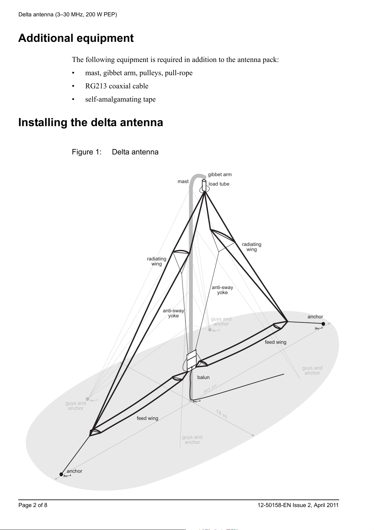
50 m
18 m
gibbet arm
load tube
mast
balun
feed wing
feed wing
radiating
wing
radiating
wing
anchor
anchor
anti-sway
yoke
anti-sway
yoke
guys and
anchor
guys and
anchor
guys and
anchor
guys and
anchor
Additional equipment
The following equipment is required in addition to the antenna pack:
• mast, gibbet arm, pulleys, pull-rope
• RG213 coaxial cable
• self-amalgamating tape
Installing the delta antenna
Figure 1: Delta antenna
Page 2 of 8 12-50158-EN Issue 2, April 2011

Delta antenna (3–30 MHz, 200 W PEP)
guys and
anchor
guys and
anchor
guys and
anchor
guys and
anchor
23 m 23 m
anchor
rope
anchor
rope
10 m
mast and
gibbet arm
feed wing
radiating
wing
feed wing
radiating
wing
anchoranchor
Connecting the delta antenna to the balun mounting plate and the load tube
To connect the delta antenna:
1 Determine the location and orientation of the antenna to suit the site (see Figure 2
and Figure 3).
If a guyed mast is used, the guys should be made from electrically
NOTE
insulating material. If the guys are made from metal they should be
segmented by suitable strain insulators.
1 Install RG213 coaxial cable to an appropriate location near the base of the mast.
A UHF-type plug is required on the coaxial cable. This connects to the UHF-type
socket on the balun. When mounted on the mast, the balun is 1.8 m above the
ground.
NOTE If possible, install the cable underground in a weather-proof conduit.
It is recommended that lightning arresters are installed in the coaxial
NOTE
cable at the base of the antenna and at the entry point to the building
where the equipment is housed.
Figure 2: Plan view of the installation
12-50158-EN Issue 2, April 2011 Page 3 of 8

Delta antenna (3–30 MHz, 200 W PEP)
guys and
anchor
guys and
anchor
1.8 m
load tube
balun
anti-sway
yoke
anti-sway
yoke
15 m
1 m
mast and
gibbet arm
feed wing
radiating
wing
feed wing
radiating
wing
anchoranchor
Figure 3: Elevation of the installation
1 Assemble the mast, gibbet arm and pulleys according to the manufacturer’s
instructions. Align the gibbet arm to intersect the angle between two sets of guys.
1 Attach a pulley to the outer end of the gibbet arm using a D-shackle.
1 Tie a pull-rope to the polypropylene rope, then thread the pull-rope down the centre
of the mast.
The polypropylene rope must be located on the outside of the mast.
1 Tie off the pull-rope and polypropylene rope temporarily to the bottom of the mast.
1 Raise and secure the mast with guys according to the manufacturer’s instructions.
1 Use the U-bolts on the balun mounting plate to attach it to the mast so that the
bottom of the plate is at a height of 1.8 m above the ground, directly below the plane
of the gibbet arm.
NOTE The UHF-type socket on the balun must face downwards.
CAUTION Do not overtighten the U-bolts on the mounting plate.
1 Unroll each set of antenna wires, laying them out straight, then orientating as shown
in Figure 4 on page 5.
CAUTION Take care not to damage the porcelain insulators.
Page 4 of 8 12-50158-EN Issue 2, April 2011

Figure 4: Laying out the antenna wires
7 m
gibbet arm
load tube
mast
balun
feed wing
feed wing
radiating
wing
radiating
wing
anchor
anchor
anti-sway
yokes
guys and
anchor
guys and
anchor
guys and
anchor
guys and
anchor
anchor rope
anchor rope
long
spreader
long
spreader
short
spreader
short
spreader
short
spreader
short
spreader
pull-rope
polypropylene
rope
Delta antenna (3–30 MHz, 200 W PEP)
1 Connect the inner end of each feed wing to the corresponding lower hole on the
balun mounting plate using the D-shackle provided (see Figure 5 on page 6).
CAUTION
CAUTION
When hoisted, the feed wings must be in the horizontal plane for
effective operation.
Do not connect the terminating tail wires to the porcelain insulators
on the balun; these are attached after the antenna is raised and a
measurement is taken.
12-50158-EN Issue 2, April 2011 Page 5 of 8

Delta antenna (3–30 MHz, 200 W PEP)
Figure 5: Connections to the balun mounting plate
hole with D-shackle
for anti-sway yoke
connection
mounting
plate
feed wing
(in horizontal plane)
terminating
tail wires
porcelain
insulator
mast
U-bolt
hole with D-shackle
for anti-sway yoke
connection
porcelain
insulator
balun
UHF-type socket
feed wing
(in horizontal plane)
U-bolt
terminating
tail wires
Figure 6: Connections to the load tube
polypropylene
rope
bow
shackle
porcelain
insulator
terminating
tail wires
porcelain
insulator
load tube
terminating
tail wires
radiating
wing
radiating
wing
Page 6 of 8 12-50158-EN Issue 2, April 2011
Delta antenna (3–30 MHz, 200 W PEP)
1 Connect the polypropylene rope to the top of the load tube using the bow shackle
provided (see Figure 6 on page 6).
1 Connect each radiating wing to the corresponding D-shackle at the bottom of the
load tube.
1 Connect the terminating tail wires to the corresponding porcelain insulator on the
load tube using two 8 mm AF spanners to prevent the inner nut from rotating.
WARNING Ensure that the terminating tail wires to not touch the load tube.
1 Cut a very small hole in the corner of the packet of conductive grease.
1 Apply a small amount of conductive grease to each connection between the tail
wires and the insulators.
1 Attach a long spreader to each of the radiating wings by fitting it over the crimped
ferrules that are approximately 7 m from the connection of the radiating wing to the
load tube (see Figure 4 on page 5).
1 Fix each long spreader in place at each end using the split pins provided in the
accessory bag.
1 Ensure the anti-sway yoke attached to each long spreader is positioned so that it will
hang below the radiating wing when the antenna is raised.
1 Attach a short spreader to each end of the feed wings by fitting it over the crimped
ferrules that are approximately 600 mm from each end of the feed wings (see
Figure 4 on page 5).
1 Fix each short spreader in place at each end using the split pins provided in the
accessory bag.
Raising and tensioning the delta antenna
To raise and tension the delta antenna:
1 Slowly raise the antenna using the pull-rope and polypropylene rope until it is 2 m
from the top of the mast.
NOTE
Continuously check that the antenna wires are not tangled or twisted,
and that the anti-sway yokes hang below the antenna wires.
1 Secure the polypropylene rope to the mast loosely using two of the rope grips
provided in the accessory bag.
1 Use two of the rope grips to connect each anchor rope to its corresponding anchor
point, applying enough tension to lift the feed wings from the ground.
1 Secure each anchor rope loosely.
1 Increase the tension on the polypropylene rope and/or the anchor rope on each side
of the antenna until:
• each feed wing is horizontal and sags approximately 300 mm in the centre, and
• each radiating wing sags approximately 1 m at the long spreader
12-50158-EN Issue 2, April 2011 Page 7 of 8

Delta antenna (3–30 MHz, 200 W PEP)
1 Tighten all rope grips.
1 Attach the anti-sway yoke from each radiating wing to the corresponding top hole in
the balun mounting plate using the D-shackle provided (see Figure 5 on page 6).
NOTE
1 Untie the pull-rope from the polypropylene rope and retain for future lowering and
raising of the antenna.
Connecting the balun to the delta antenna and the RF source
To connect the balun into the antenna system:
1 Measure the resistance between the terminating tail wires from the feed wings.
The resistance should measure 600 ±100 . If not, check the connections to the
load tube.
Only a small amount of tension is required on the anti-sway yokes as
some sideways movement is desirable to improve the mechanical life
of the antenna.
1 Connect the terminating tail wires from each feed wing to the corresponding
1 Apply a small amount of conductive grease to each connection between the tail
1 Connect the RF cable to the balun, then tighten.
1 Apply self-amalgamating tape to the RF connection to seal it against water ingress.
1 Connect the earth for the mast to a suitable ground stake.
Maintenance
The area around the antenna must be kept clear of foliage.
The antenna should be inspected a short time after installation and re-tensioned if
necessary. The installation should be inspected every 6 months.
porcelain insulator on the balun (see Figure 3 on page 4) using two 8 mm AF
spanners to prevent the inner nut from rotating.
WARNING Ensure that the terminating tail wires to not touch the balun.
wires and the insulators.
Page 8 of 8 12-50158-EN Issue 2, April 2011
 Loading...