

Page 1
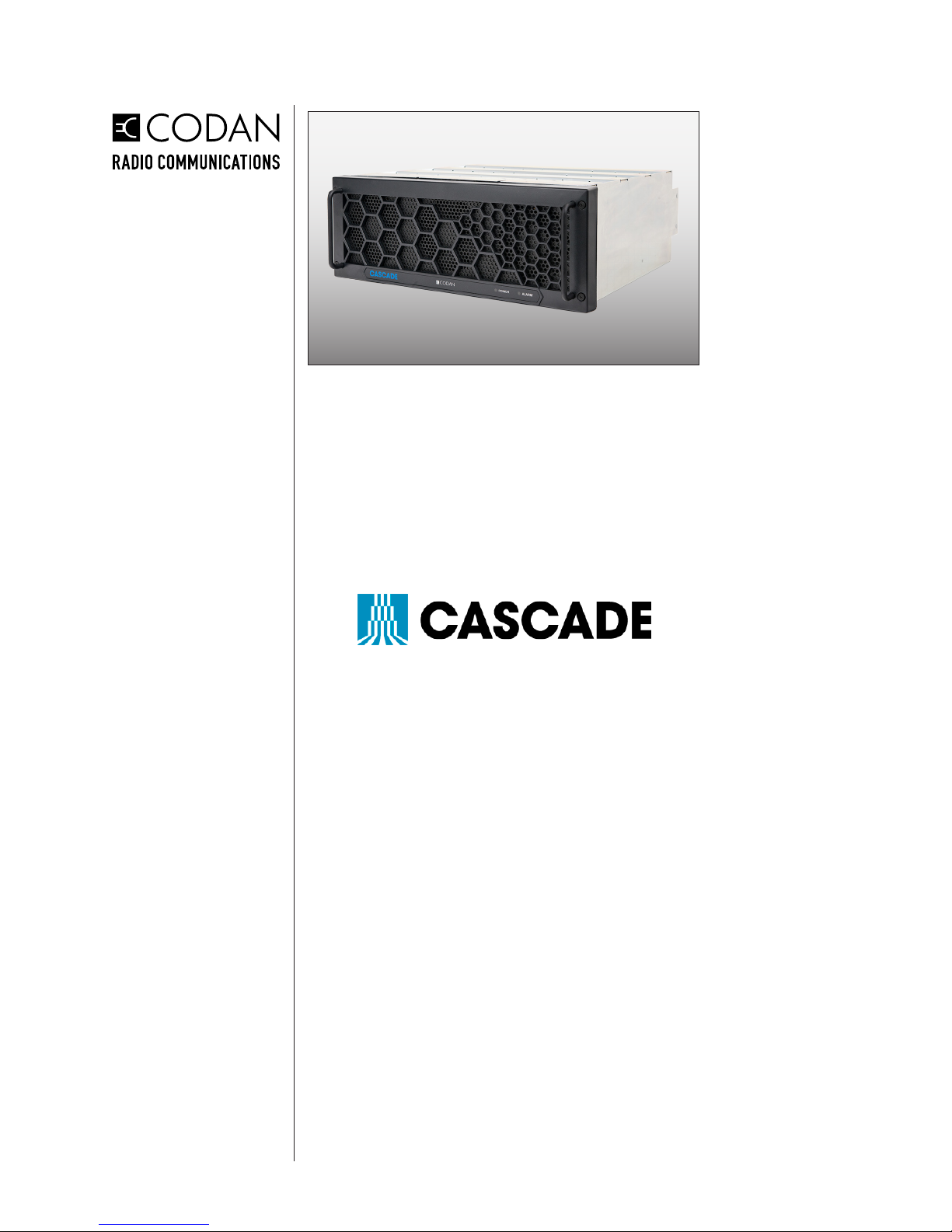
CASCADE SYSTEM
MODULES
OPERATION GUIDE
© 2018 Codan Limited.
No part of this guide may be reproduced, transcribed, translated into any
language or transmitted in any form whatsoever without the prior written
consent of Codan Limited.
CODAN™, NGT™, Easitalk™, CIB™ and CALM™ are trademarks of
Codan Limited. Other brand, product, and company names mentioned
in this document are trademarks or registered trademarks of their
respective holders.
The English version takes precedence over any translated versions.
Document Number:
Revision:
Revision Date:
Security Classication:
OG-CASC-SYS-MOD
1-0-1P
May 2018
PUBLIC
Codan Radio Communications
Victoria, BC
PRINTED IN CANADA
Page 2

ii
DOCUMENT CONTROL
DOCUMENT REVISION
DEFINITION
This document has been produced, veried and controlled in accordance
with Quality Management System requirements.
Please report any errors or problems.
Documentation uses a three-level revision system. Each element of
the revision number signies the scope of change as described in the
diagram below.
1-0-0
Major Revisions:
The result of a major change to
product function, process or requirements.
Minor Revisions:
The result of a minor change to
product, process or requirements.
Editorial Revisions:
The result of typing corrections or
changes in formatting, grammar or wording.
NOTE
Three-level revision numbers start at 1-0-0 for the rst release. The
appropriate element of the revision number is incremented by 1 for each
subsequent revision, causing any digits to the right to be reset to 0.
For example:
If the current revision = 2-1-1 Then the next major revision = 3-0-0
If the current revision = 4-3-1 Then the next minor revision = 4-4-0
If the current revision = 3-2-2 Then the next editorial revision = 3-2-3
Document revision history is provided at the back of the document.
The user’s authority to operate this equipment could be revoked through
any changes or modications not expressly approved by Codan Limited.
The design of this equipment is subject to change due to continuous
development. This equipment may incorporate minor changes in detail
from the information contained in this manual.
Operation is subject to the following two conditions: (1) this device may
not cause interference, and (2) this device must accept any interference,
including interference that may cause undesired operation of the device.
Cascade System Modules Operation Guide
OG-CASC-SYS-MOD-1-0-0P
Page 3

Cascade System Modules Operation Guide
OG-CASC-SYS-MOD-1-0-0P
RF Exposure Warning
Exposure to radio frequency (RF) energy has been identied as a potential environmental factor that must be
considered before a radio transmitter can be authorized or licensed. The FCC and IC have therefore developed
maximum permissible exposure (MPE) limits for eld strength and power density, listed in FCC 47 CFR § 1.1310
and IC RSS-102 Issue 5 Sect 4. The FCC has furthermore determined that determination of compliance with these
exposure limits, and preparation of an Environmental Assessment (EA) if the limits are exceeded, is necessary
only for facilities, operations and transmitters that fall into certain risk categories, listed in FCC 47 CFR § 1.1307
(b), Table 1. All other facilities, operations and transmitters are categorically excluded from making such studies or
preparing an EA, except as indicated in FCC 47 CFR §§ 1.1307 (c) and (d).
KDB 447198 D01 General RF Exposure Guidance v06 and IC RSS-102 Issue 5 provide assistance in determining
whether a proposed or existing transmitting facility, operation or device complies with RF exposure limits. In
accordance with KDB 447198 , FCC 47 CFR § 1.1307 (b) and RSS-102 Issue 5 Sect 2.5, the Codan Radio
Communications transmitter manufactured in Canada is categorically excluded from routine evaluation or preparing
an EA for RF emissions and this exclusion is sufcient basis for assuming compliance with FCC/IC MPE limits. This
exclusion is subject to the limits specied in FCC 47 CFR §§ 1.1307 (b), 1.1310 and IC RSS-102 Issue 5 Sect 4.
Codan Radio Communications has no reason to believe that the excluded transmitter encompasses exceptional
characteristics that could cause non-compliance.
Notes:
• The FCC and IC’s exposure guidelines constitute exposure limits, not emission limits. They are relevant
to locations that are accessible to workers or members of the public. Such access can be restricted or
controlled by appropriate means (i.e., fences, warning signs and others).
• The FCC and IC’s limits apply cumulatively to all sources of RF emissions affecting a given site. Sites
exceeding these limits are subject to an EA and must provide test reports indicating compliance.
RF Safety Guidelines and Information
Base and Repeater radio transmitters are designed to generate and radiate RF energy by means of an external
antenna, typically mounted at a signicant height above ground to provide adequate signal coverage. To reduce
potential radio interference to other users, the antenna type and its gain should be so chosen that the equivalent
isotropically radiated power (EIRP) is not more than that permitted for successful communication. The following
antenna installation guidelines must be adhered to in order to ensure RF exposure compliance:
Non-building-mounted Antennas:
• Height above ground level to lowest point of antenna ≥ 10 m
• Power ≤ 1000 W ERP (1640 W EIRP)
Building-mounted Antennas:
Power ≤ 1000 W ERP (1640 W EIRP)
The following RF Safety Guidelines should be observed when working in or around transmitter sites:
• Do not work on or around any transmitting antenna while RF power is applied.
• Before working on an antenna, disable the appropriate transmitter and ensure a “DO NOT USE”
or similar sign is placed on or near the PTT or key-up control.
• Assume all antennas are active unless specically indicated otherwise.
• Never operate a transmitter with the cover removed.
• Ensure all personnel entering a transmitter site have electromagnetic energy awareness training.
For more information on RF energy exposure and compliance, please refer to the following:
1. FCC Code of Regulations; 47 CFR §§ 1.1307 and 1.1310
2. KDB 447198 D01 General RF Exposure Guidance v06
3. https://www.fcc.gov/general/radio-frequency-safety-0
4. IC RSS-102 Issue 5, “Radio Frequency Exposure Compliance of Radio Communication
Apparatus”
iii
Page 4
��
10
( )
iv
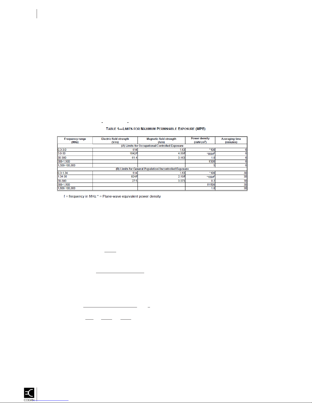
RF Maximum Permissible Exposure (MPE)
Exhibit Requirements for Installations in the United States of America
FCC Part 1, Section 1.1307 table 1- Transmitters, Facilities and Operations Subject to Routine Environmental Evaluation states the following for Part 90 Devices:
• Part 90 devices Non-building-mounted antennas: height above ground level to lowest point of antenna <10 m and power >1000 W ERP (1640 W
EIRP). Building-mounted antennas: power >1000 W ERP (1640 W EIRP).
Another way of wording this is that Part 90 devices are not Subject to Routine Environmental Evaluation when the antenna is installed a t 10M et ers or higher and
operating total power level of all channels is less than 1640 Watts EIRP.
As an example, a 125W transmitter with a 10dB gain antenna with a low loss cable would translate into 1,000 Watts EIRP in the envelope lobe. If it is mounted
10 Meters or higher above where people could be walking, you have a safe installation and do not have to perform MPE calculations for safe distance.
No antenna
If the antenna is lo wer than 10Meters then you need to verify that your installation is at a safe distance for Exposure to the General Population.
For United States installations, you must ensure that your installation complies with the Maximum Permissible Exposure (MPE) requirem ents for general
population that are specified unde r FCC Part 1 Section 1.1310 Table 1.
is supplied with this unit. Some suggested antennas are:
- Manufacturer: Sinclair Model: SC225 Gain: 0 dBd (2.15 dBi)
- Manufacturer: Sinclair Model: SC233 Gain: 3 dBd (5.15 dBi)
- Manufacturer: Sinclair Model: SD114 Gain: 7.5 dBd (9.65 dBi)
For US Installations, the maximum power density resulting from the co mposite Effect ive Isotopic Radiated Power (EIRP) from the antenna connected to this
equipment must be limited to the maximum permissible exposure as stated below:
• Power density limit for the band 152 to 174MHz = 0.2 mW/cm²
MPE and Safe Di stance Calculations fo r USA Installations
This Power Density value is determined by the combination of RF output, cable loss, antenna gain, and distance from the an tenna when energized.
The MPE calculation for US installations is expressed as follows:
• Power Density Pd (mW/cm²) = (
Where
• d = distance from the antenna expressed in cm.
•
EIRP expressed in mW
��������
��∗��∗��
[
���� ������ (������)+������ �������� (������)−
(
=
10
)
����
������ ����
���� (����)]
10
)
• Tx Power (dBm) = 10*log[Tx Power (mW)]
As an example, with the transmitter running at 125 watts output into an antenna with a gain of 10 dBi using a short cable with 0dB loss, to verify if 650cm
(6.5meters) is a safe distance from the antenna to ensure ex posure compliance of 0.2mW/cm
1) 125 Wa
2) EIRP (mW) = 10
3) Pd (mW/cm2 ) =
tts Tx Power = 51dBm
[
���� ������ (50������)+
(
EIRP
(
) = (
4∗π∗d24∗��∗650
������ �������� (10������)−
1,000,000
) = (
2
����
������ ����
1,000,000
5,309,291
���� (0����)
]
)
=
)
=0.19 mW/cm
60
10
10
= 1,000,000mW
2
:
2
• 6.5 meters (21.125 Feet) is a safe distance for US installations when using a 10dBi Antenna.
The minimum safe distance, from a radiating structure using different Gain Antennas”
• For the Band 152 to 174MHz with 2dBi Gain Antenna: d (safe distance) = 2.6 m
• For the Band 152 to 174MHz with 6dBi Gain Antenna: d (safe distance) = 4.0 m
• For the Band 152 to 174MHz with 10dB i Gain Antenna: d (safe distance) = 6.5 m
Cascade System Modules Operation Guide
OG-CASC-SYS-MOD-1-0-0P
Page 5
•
( )
RF Maximum Permissible Exposure (MPE)
- Manufacturer: Sinclair
Model: SC225
Gain: 0 dBd (2.15 dBi)
- Manufacturer: Sinclair
Model: SC233
Gain: 3 dBd (5.15 dBi)
- Manufacturer: Sinclair
Model: SD114
Gain: 7.5 dBd (9.65 dBi)
Exhibit Requirements for Installations in Canada
No antenna is supplied with this unit. Some suggested antenna s a re :
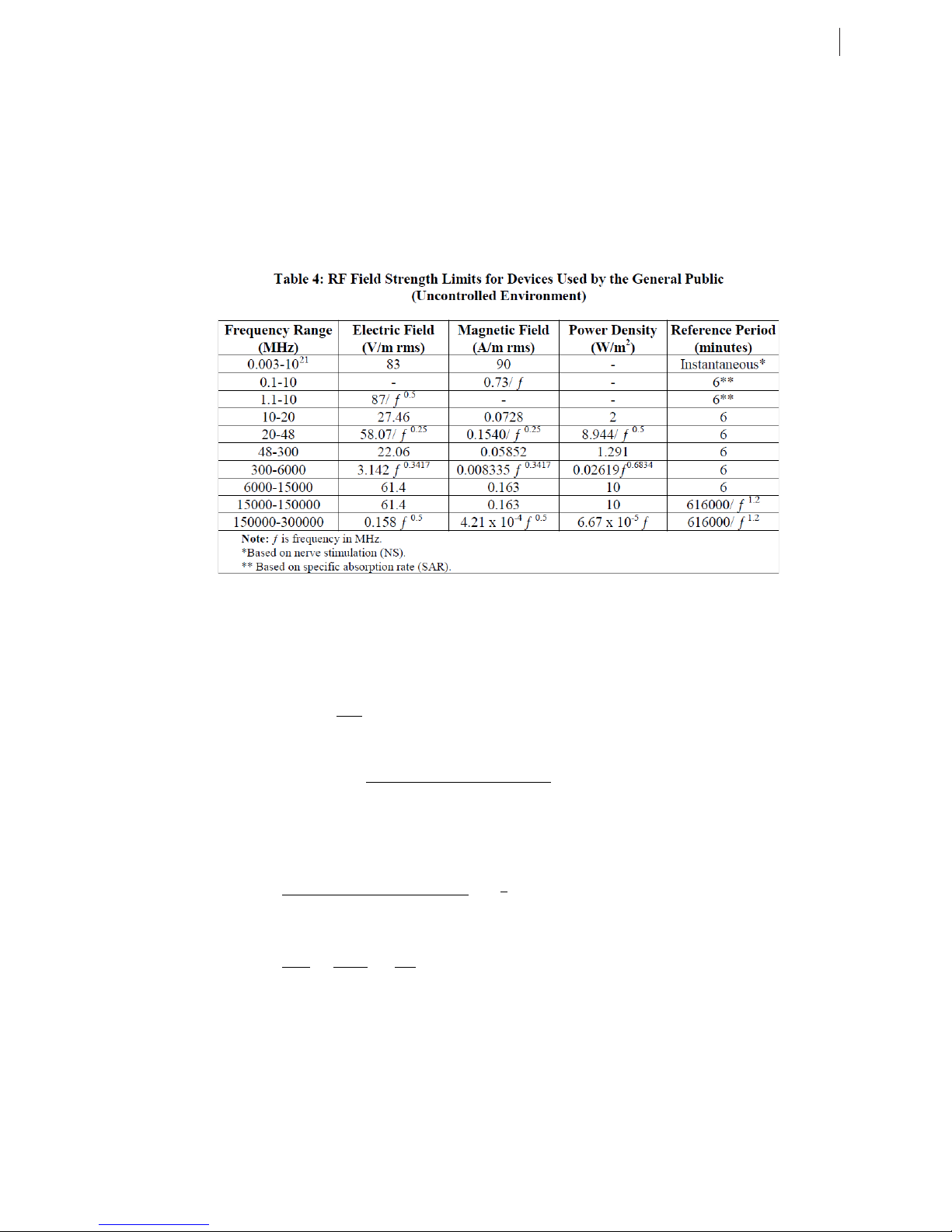
For Canada installations, you must ensure that your installation complies with the Maximum Permissible Exposure (MPE) requirements for general population
that are specified under RSS-102 Section 4 Table 4.
v
MPE and Safe Distance Calculations for Canada Installations
For Canada installations, the maximum power density resulting from the composite Effective Isotopic Radiated Power (EIRP) from the antenna connected to this
equipment must be limited to the maximum permissible exposure as stated below:
•
Power density limit for the band 152 to 174MHz
The MPE calculation for US is expressed as follows:
��������
��∗��∗��
=
10
Where
Power Density Pd (W/m²) =
•
d
= distance from the antenna expressed in meters (m).
•
EIRP expressed in Watts (W)
•
Tx Power (dBW)
= 10*log[Tx Power (W)]
��
[���� ������ (������)+������ �������� (������)−����
(
= 1.291 W/m²
10
������ ����
���� (
����)]
)
As an example, with the transmitter running at 125 watts output into an antenna with a gain of 10 dBi using a short cable with 0dB loss, to verify if 7.5meters is
a safe distance from the antenna to ensure exposure compliance of 1.21W/m2:
4) 125 Watts Tx Power = 20.97dBW
[���� ������ (20������)+������ �������� (10������)−����������
(
1,000
) = (
10
1,000
2
5) EIRP (W) =
6) Pd (W/m2) =
•
8.5 meters is a safe dista nce for Canada installa t i o ns when using a 10dBi gain antenna.
When installing the a
10
EIRP
(
) = (
4∗π∗d24∗��∗8.5
ntenna, the above relationship should be used to ensure the combination of power, antenna gain, and distance is such that the maximum
permissible power density is not exceeded. Different combinations of output power and antenna gain will result in different minimum safe distances.
The minimum sa f e distance , fr om a radiat i ng s tructure using differe nt Gain Antennas”
•
•
•
For the Band 152 to 174MHz with 2dBi Gain Antenna: d (safe distance) = 3.5 m
For the Band 152 to 174MHz with 6dBi Gain Antenna: d (safe distance) = 5.5 m
For the Band 152 to 174MHz with 10dBi Gain Antenna: d (safe distance) = 8.5 m
����
)
=1.11 W/m
907.9
���� (0����)]
)
(30)
10
=
10
= 1,000W
2
Page 6

This Page Intentionally Left Blank
vi
Cascade System Modules Operation Guide
OG-CASC-SYS-MOD-1-0-0P
Page 7

Contents
vii
General Information ...............................................................9
Introduction ................................................................................................9
Base Station / Repeater Specications .................................................... 10
Safety Information ................................................................ 13
Important Safety Warnings ....................................................................... 13
Subrack and Front Panel Safety .............................................................. 15
Regulatory Information ......................................................... 17
System Setup ....................................................................... 19
Unpack the Subrack ................................................................................. 19
Module Congurations ............................................................................. 20
Cascade Web GUI ................................................................................... 21
Cascade Theory of Operation .............................................. 23
Cascade Power Supply ........................................................ 25
Introduction .............................................................................................. 25
Installation ................................................................................................ 26
Power Connections .................................................................................. 26
Theory of Operation ................................................................................. 28
Cascade Transceiver ........................................................... 31
Introduction .............................................................................................. 31
Receiver Theory Of Operation ................................................................. 32
Transmitter Theory Of Operation .............................................................33
Cascade Power Amplier ..................................................... 35
Introduction .............................................................................................. 35
Installation ................................................................................................ 36
Connections ............................................................................................. 36
Theory of Operation ................................................................................. 36
Product Labeling .................................................................. 39
Power Supply Labels ............................................................................... 39
Transceiver Labels ................................................................................... 40
Power Amplier Labels ............................................................................41
Front Panel and Subrack Labels .............................................................. 42
Glossary of Terms ................................................................ 43
Cascade System Modules Operation Guide
OG-CASC-SYS-MOD-1-0-0P
Page 8

This Page Intentionally Left Blank
viii
Cascade System Modules Operation Guide
OG-CASC-SYS-MOD-1-0-0P
Page 9

GENERAL INFORMATION
INTRODUCTION
The CASCADE product continues the Codan Radio Communications tradition of module-based
products, where module capability expands into systems capability. CASCADE comes in a compact
rack form factor of 19-inch width and 4U height, providing the exibility of a mix of transceivers /
power amplifier pairs; six receivers only or a mix of modules. From a transmitting point of view,
CASCADE offers up to two 125-watt power amplifier / transceiver pairs capable of not only P25
Phase I, but also LSM and P25 Phase II.
9
This guide covers operation information for the CASCADE System subrack and front panel, and
includes details on individual modules: DC-DC Power Supply, VHF Power Ampli
Transceiver.
er and VHF
Cascade System Modules Operation Guide
OG-CASC-SYS-MOD-1-0-0P
Page 10

General Information
10
BASE STATION / REPEATER SPECIFICATIONS
RECEIVER (RX)
FCC Frequency Band: 150.8 to 173.4 MHz
IC Frequency Band: 148 to 174 MHz
Channel Spacing: 12.5 kHz
Channel Step Size: 1.25 kHz
Blocking Rejection: ≥ 100 dB
Frequency Switching Range: Full Band
Reference Sensitivity (12 dB SINAD & 5% BER): ≤ -120 dBm
Adjacent Channel Rejection: ≥ 60 dB
Conducted Spurious Output Power (Analog): ≤ -95 dBm (9 kHz to 1 GHz)
Intermodulation Rejection: ≥ 80 dB
Hum & Noise Ratio: *N/A
L.O. Frequency Stability: ≤ ± 0.5 ppm
Audio Distortion (Analog): *N/A (≤ 2%)
Audio Output Level (600 Ω Balanced): *N/A
TRANSMITTER (TX)
FCC Frequency Band: 150.8 to 173.4 MHz
IC Frequency Band: 148 to 174 MHz
Channel Spacing: 12.5 kHz
Channel Step Size: 1.25 kHz
Frequency Switching Range: Full Band
RF Output Power:
10 to 125W; 1W steps, adjustable
Duty Cycle: 100%
Undesired Emissions (Conducted Spurious): ≤ -90 dBc
Undesired Emissions
(Adjacent Channel Power Ratio):
≥ 67 dB
Intermodulation Attenuation: ≥ 70 dB
FM Hum & Noise Ratio: *N/A (≥ 45 dB Analog)
Carrier Frequency Stability: ≤ ± 0.5 ppm
Audio Distortion (Analog): *N/A (≤ 2%)
VSWR Protection: Any (with fold-back)
Emission Designators: 8K10F1D, 8K10F1E, 8K10F1W, 8K10F7W,
Cascade System Modules Operation Guide
OG-CASC-SYS-MOD-1-0-0P
8K70D1D, 8K70D1E, 8K70D1W,
8K70D7W,9K80D7D, 9K80D7E, 9K80D7W,
11K0F3E
Page 11

GENERAL SPECIFICATIONS:
Standby Current: ≤ 300 mA @ -48 VDC (no fan)
Transmit Current: ≤ 7.25A @ -48 VDC (@ 125W with fans)
Operating Temperature: -30 to +60°C
Dimensions (4RU): Width: Height: Depth:
48.3 cm / 19 in 17.6 cm / 6.95 in 50.2 cm / 19.8 in
General Information
11
Weight:
20.1 kg / 44.3 lbs [1 channel]
25.9 kg / 57.1 lbs [2 channel]
* CASCADE is not equipped with an analog audio input or output.
Values noted are typical.
Equipment descriptions and specications are subject to change without notice or obligation.
Cascade System Modules Operation Guide
OG-CASC-SYS-MOD-1-0-0P
Page 12

This Page Intentionally Left Blank
12
Cascade System Modules Operation Guide
OG-CASC-SYS-MOD-1-0-0P
Page 13
SAFETY INFORMATION
IMPORTANT SAFETY WARNINGS
To reduce the risk of personal injury and property damage, exercise caution and look for and comply
with the safety symbols shown below.
13
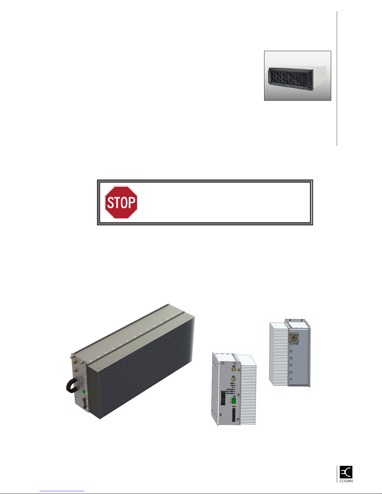
NOTE:
STOP SIGN
When this symbol is shown, DO NOT continue until the safety items identied
have been noted and addressed. Ignoring this reminder violates Codan
standards of design for the product and will most likely result in severe
personal injury or equipment damage.
CAUTION SIGN
When this symbol is shown, exercise caution and read the information
carefully. If the corresponding procedure or information is not performed
or applied correctly, the equipment may fail or performance may be
compromised and personal safety could also be compromised.
When this symbol is shown, the selected information will add clarity
to a procedure or provide additional information that will enhance the
equipment performance.
Cascade System Modules Operation Guide
OG-CASC-SYS-MOD-1-0-0P
Page 14

Safety Information
14
• Equipment Modication – DO NOT modify any parts on this
equipment. Contact Codan Radio Communications Service
Department.
• Radiation from Radio Frequency (RF) – DO NOT touch the
antenna when using the Transmitter. Always follow RF Safety
Guidelines.
• Exploding Hazard – DO NOT operate the CASCADE equipment if
ammable gas or gas fumes are present.
• RF Burn Hazard – DO NOT touch the output connector in an open
circuit condition while transmitting. The amplier RF output connector
may produce risk of RF burns if operated with the output connector
in an open-circuit condition. The power amplier should always be
operated with the specied load and connectors.
• Personal Safety – DO NOT operate or perform maintenance on the
system without direct authority from Codan Radio Communications.
Comply with all material handling regulations as many components
are heavy and moving or lifting could cause physical injury.
• Airow Restriction – DO NOT cover or restrict the cooling fans or
vents; overheating can occur and cause serious damage.
• Equipment Damage – DO NOT lift the subrack by the front panel
handles. The handles are not designed to bear the full weight of the
subrack and tted modules.
• Hot Surface Hazard – The Power Amplier surface temperature may
exceed safe touch temperatures when operated under high-power
and/or high-ambient temperature conditions.
• Shock Hazard – Protect all CASCADE equipment from the possibility
of lightning strikes and contact from any unspecied external power
source.
Cascade System Modules Operation Guide
OG-CASC-SYS-MOD-1-0-0P
Assembled subrack and modules weigh
over 40 pounds (18+ kilograms). A twoperson lift may be required.
Page 15

Safety Information
SUBRACK AND FRONT PANEL SAFETY
• A qualied service person is required to access the front panel area, even with equipment
energized
• An unqualied user should not remove the front panel as no access is required to this area for
any routine operation of the system
• The CASCADE subrack and modules should be well ventilated and free from high humidity and
excess dust and dirt
Front Panel Installed – User Access
Hazard Description
Heat Hazard • Recirculated air may be hot in some scenarios
• Handles may remain hot after exposure to high ambient air
temperature within specications
Mechanical Improperly secured front panel may fall on operator
Radiation Acoustic noise level may be hazardous, especially in multi-rack
congurations
15
Front Panel Assembly Removed – Qualied Personnel
Hazard Description
Energy Hazard • All PSU +48V outputs and connected FIB circuits can source
hazardous energy levels
• PSU–PA power harness may remain energized at hazardous energy
levels after disconnection from PSU side (PA input capacitor charge)
Heat Hazard • TRx front panel may become hot under continuous operation
• PA front panel and heatsink ns may become hot under continuous or
intermittent operation
• All metalwork may remain at hazardous temperature following
prolonged high ambient conditions
Mechanical • Rough edges are present on the subrack; lacerations are possible
while adding or removing modules and connectors.
• Operator may crush nger between rackframe and module handle
when inserting leftmost or rightmost TRx module
Cascade System Modules Operation Guide
OG-CASC-SYS-MOD-1-0-0P
Page 16

This Page Intentionally Left Blank
16
Cascade System Modules Operation Guide
OG-CASC-SYS-MOD-1-0-0P
Page 17

REGULATORY INFORMATION
This product complies with the following safety regulations:
• FCC Title 47 – Part 22 • FCC Title 47 – Part 15
17
• FCC Regulation §15.21 • FCC Title 47 – Part 90
• ANSI C63.4-2014 • FCC Regulation §15.19
• IC RSS-GEN, Sec 8.3 • FCC Regulation §15.105
• IC RSS-102 • ICES-003
• RSS-119 Issue 12 • IC RSS-GEN, Sec 8.4
Cascade System Modules Operation Guide
OG-CASC-SYS-MOD-1-0-0P
Page 18

This Page Intentionally Left Blank
18
Cascade System Modules Operation Guide
OG-CASC-SYS-MOD-1-0-0P
Page 19

SYSTEM SETUP
19
The modules and full CASCADE subrack
are very heavy. Use extreme caution
when moving or lifting. Comply with all
material handling regulations.
UNPACK THE SUBRACK
The CASCADE subrack ships from the factory with the modules installed, based on specic customer
congurations. Unpacking procedures require two people (skilled in material handling procedures) to
unpack and move the lled subrack.
Cascade System Modules Operation Guide
OG-CASC-SYS-MOD-1-0-0P
Page 20

20
System Setup
MODULE CONFIGURATIONS
The following images identify the modules and their positioning in the subrack (see Figures 1–3).
Front Panel Removed –
Exploded View
Transceiver #1
FIGURE 1: Complete CASCADE System
PA #1
FIGURE 2: CASCADE System – Front View Two Channels Option
Blanking
Panel
PA #2
Power
Supply
Transceiver #2
Transceiver #2
Power
Supply
PA #2
Blanking
Panel
PA #1
Transceiver #1
FIGURE 3: CASCADE System – Rear View Two Channels Option
Cascade System Modules Operation Guide
OG-CASC-SYS-MOD-1-0-0P
Page 21

System Setup
CASCADE WEB GUI
CASCADE Web GUI is an innovative user interface for the CASCADE system. The GUI has many
unique features including:
• Full remote access to the Cascade system – no need be preset at the radio site
• Remote access uses standard IT infrastructure – no need for adding communication
infrastructure
• Most common Web browsers gives full access to the system – no need to install User
Interface software.
• Access restrictions are implemented by using Login and Password protection
• Communication protocols are secure and encrypted
• Single User Interface let user manage multiple transceivers at one time
• Multiple features of the User Interface enables, but is not limited to:
• Conguring receivers and transmitters
21
• Managing users and passwords
• Updating rmware and software
• Saving and loading system congurations
• Monitoring the system”s real time status
• Performing basic PTT and BER tests
Cascade System Modules Operation Guide
OG-CASC-SYS-MOD-1-0-0P
Page 22

This Page Intentionally Left Blank
22
Cascade System Modules Operation Guide
OG-CASC-SYS-MOD-1-0-0P
Page 23

CASCADE THEORY OF OPERATION
The CASCADE product is capable of acting as an RF repeater or base station with up to
two “Simultaneous Receive Channels” and up to two 125W “Simultaneous Transmit
Channels”.
23
The CASCADE product is comprised of the following:
• A Subrack which houses all of the CASCADE Components (see Figure 4)
• A Power Supply, either AC to DC or DC to DC which supplies electrical power to all the
modules
• Up to two RF Transceiver modules
• Up to two RF Power Amplier modules
• A Front Panel which contains cooling fans and control circuitry
• A Front Interface Board which handles all the module to module communication
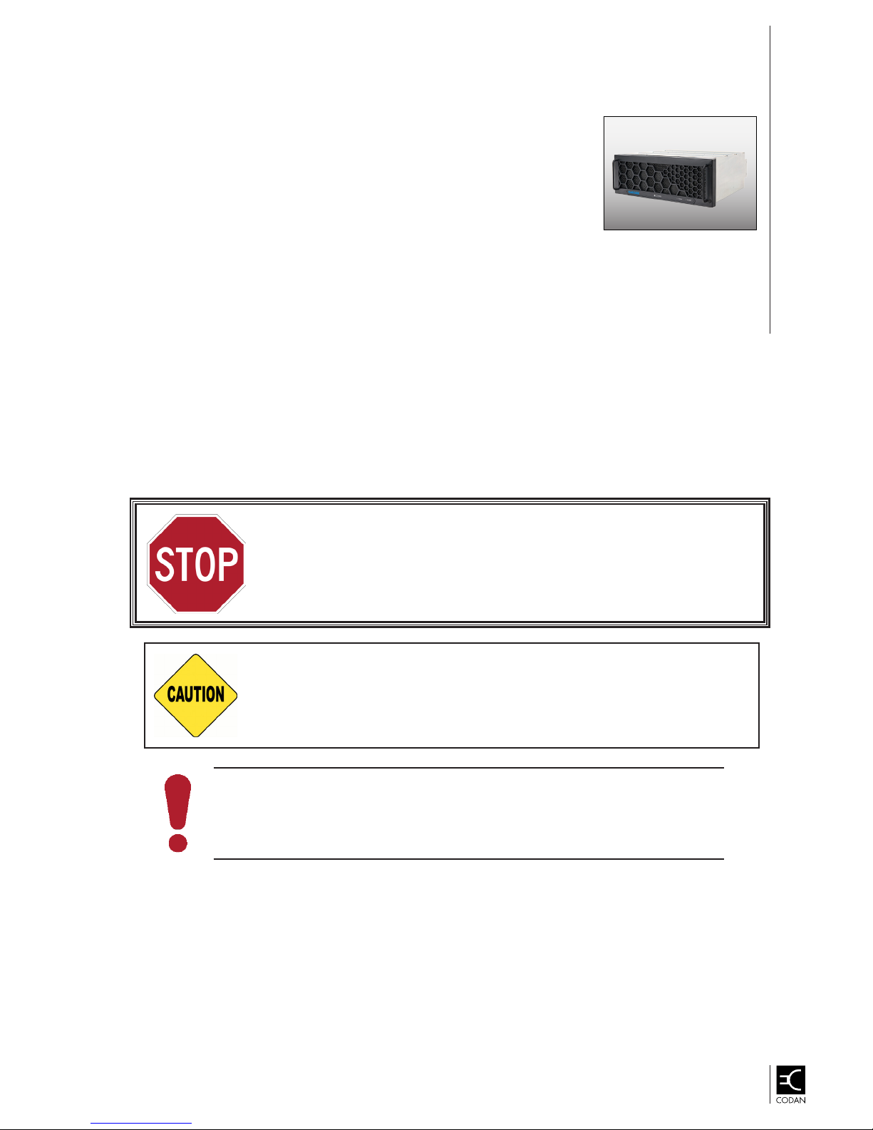
DO NOT LIFT the system
by these handles. The
handles are designed to
remove and install the
front panel, not to bear
weight.
FIGURE 4: CASCADE Front Panel and Installed Modules
Cascade System Modules Operation Guide
OG-CASC-SYS-MOD-1-0-0P
Page 24

Cascade Theory of Operation
24
The CASCADE system requires adequate ventilation and ALL vents must be
kept clear. The cooling fans will only work when the front panel is properly
in place. Cooling airow moves from the front of the unit to the rear of the
subrack so the airow must not be restricted in any way.
Cascade System Modules Operation Guide
OG-CASC-SYS-MOD-1-0-0P
Page 25

CASCADE POWER SUPPLY
INTRODUCTION
The power supply (PSU) is a DC-DC converter providing a low noise output with an ultra-high
ef
ciency above 94.5%. It delivers up to 2x16.7A output current with 48V output voltage and is
capable of operating from -30°C to 60°C. See Figure 5 for images of the CASCADE power supply.
25
The power supply is designed to provide sufficient power for a full CASCADE subrack containing
two transceivers, two 125W power amplifiers, three fans and an option slot. The PSU can also be
used in other configuration requiring less current, for example, a multiple receiver configuration (up
to six transceivers).
PSU Front View
PSU Rear View
FIGURE 5: Power Supply – Side Front and Rear Views
Cascade System Modules Operation Guide
OG-CASC-SYS-MOD-1-0-0P
Page 26

Cascade Power Supply
26
INSTALLATION
The PSU slides in the 5th slot from the left of the CASCADE subrack (see Figure 6). The PSU is
fastened with four Phillips screws in the front.
FIGURE 6: PSU Installed in Subrack
POWER CONNECTIONS
The power supply is NOT protected against reverse polarity and may get
damaged, overheat and/or cause re if not connected properly. The metal
enclosure is labeled showing the positive and the negative polarity.
The PSU requires a DC power source providing a voltage between the operational ranges specied in
the product specications. The connector MUST BE CONNECTED WITH THE RIGHT POLARITY.
A ground connection is required on the back of the PSU using an M5 x 12 screw already installed
(see Figure 7).
FIGURE 7: Ground Connection – Screw Installed
Cascade System Modules Operation Guide
OG-CASC-SYS-MOD-1-0-0P
Page 27

Cascade Power Supply
A 13.8V auxiliary connection is also located on the back of the enclosure. The connection polarity is
labeled on the back of the enclosure (see Figure 8).
Polarity Labels
FIGURE 8: Power Supply Rear Panel – Connection Polarity
27
On the front the power supply are four connectors (see Figure 9). The top two connectors are
intended for connection to the two power ampliers. The six-pin 48V Common connection must be
connected to the Front Interface Board (FIB) using the appropriate cable.
The last connector on the front bottom is used to communicate with the other CASCADE components
The connector uses a ribbon cable and is connected to the FIB in the connector (J5).
Power Amplier Connectors
Six-Pin FIB Connector
Locking Jaw Connector
FIGURE 9: Power Supply Front panel Connectors
Cascade System Modules Operation Guide
OG-CASC-SYS-MOD-1-0-0P
Page 28
Cascade Power Supply
28
THEORY OF OPERATION
The PSU is designed to offer a stable, low noise, output signal of 48V. The main components are
the two bricks converting the input voltage into 48V. Mounted on the mainboard (DC-DC -48V to 48V
Isolated PSU) these bricks are designed for telecommunication purposes and provide the isolation
required for CASCADE operation. An auxiliary board (-48V to 13.8V Isolated AUX) is also attached to
the mainboard providing a 13.8V output voltage for external use.
Input Filter
The input lter is used to limit the conducted emissions of the power supply and offer ltering for noise
coming in or out of the PSU.
The PSU is designed to be used in a CASCADE subrack with the
fan assembly running. The PSU is not designed to be used as a
standalone unit because it requires cooling for normal operations.
Temperature Sensors
For temperature monitoring, sensors (U11 and U12)—located close to the bricks—are monitoring
the 48V board temperature and sending the exact temperature to the microcontroller (U10). The
microcontroller in turn sends the measurements to the other components of the CASCADE via the
FIB connection to control the fan speed.
For over-heating, three levels of protection are included:
1. Software Protection – if the temperature is too high, the CASCADE fan control system will
automatically increase the fan speed to lower the internal temperature of the PSU.
2. Pre-set Temperature Protection – from the bricks themselves.
3. Thermostats – (48V: Q2, Q4 / 13.8V: Q2) connected to the On/Off connection and at a factory
preset temperature of 95°C. These thermostats turn the converter OFF if the board temperature
is higher than the preset temperature.
Voltage and Current Measurement
For the 48V right and left and the 13.8V, the current and voltage is measured independently and the
information is transmitted to the microcontroller. The microcontroller is comparing the levels within its
preset nominal levels and enables the corresponding LED in the front of the enclosure. In case of
errors, the alarm light will be ON and the corresponding output LED will be OFF.
Cascade System Modules Operation Guide
OG-CASC-SYS-MOD-1-0-0P
Page 29

Cascade Power Supply
Auxiliary Voltages
For the digital section of the 48V board, three different voltage levels are required:
• 5.6V (U15)
• 5V (U9)
• 3.3V (U16)
The voltage converters receive an input from the DIG_Vcircuit powered by either the auxiliary 48V
coming out of U2, U5 or the 13.8V.
Microcontroller (U10)
The power supply’s logic is only used to report its state, including: voltages, currents and temperature
to the other components of the CASCADE. The microcontroller receives input from different sections
of the PSU and can activate LED lights in the front of the unit and transmit this information via the
FIB.
Alarms and Status
29
Five LED lights on the front of the enclosure provide the basic information about the power supply
status. These LEDs include:
• Power Light (PWR)
• Alarm Light (ALM)
• 48V Left Status (48V LEFT)
• 48V Right Status (48V RIGHT)
• 13.8V Status (13.8V OUT)
Two signals: IOG_48V_LEFT and IOG_48V_RIGHT are also used to monitor the status of each
DC-DC Converter brick.
Operation
To operate the power supply, an output enable button located in the back of the enclosure turns the
device’s output ON (see Figure 10).
FIGURE 10: Output Enable Button Location
Cascade System Modules Operation Guide
OG-CASC-SYS-MOD-1-0-0P
Page 30

Cascade Power Supply
30
Protection
DC-DC -48V to 48V Isolated PSU Board
Input
Name Fuse Type Location
48V Right 40A, 250V Fast-Acting (F5) Inside the enclosure
48V Left 40A, 250V Fast-Acting (F2) Inside the enclosure
Output
Name Type Location
48V_L_FP 3.75A, Resettable (F5) (Section 5.3) Inside the enclosure
48V_R_FP 3.75A, Resettable (F3) (Section 5.3) Inside the enclosure
48V_C_FP 3.75A, Resettable (F4) (Section 5.3) Inside the enclosure
+48V_L Internal. Foldback, then hiccup past 17.6A In U2
+48V_R Internal. Foldback, then hiccup past 17.6A In U2
1
Refer to the PSU block diagram in the CASCADE Power Supply section for details.
1
1
-48V to 13.8V Isolated AUX PSU
Input
Fuse Type Location
48V 2A, 250V Fast-Acting (F3) Inside the enclosure
Output
Fuse Type Location
13.8V 2A, 250V Fast-Acting (F1) Inside the enclosure
Cascade System Modules Operation Guide
OG-CASC-SYS-MOD-1-0-0P
Page 31

CASCADE TRANSCEIVER
INTRODUCTION
The CASCADE Transceiver (TRx) is a full duplex software controlled radio (see Figure 11) and is
comprised of:
• An RF PCB that contains the Transmit, Receive and Clock Distributions sections
• A Digital PCB that contains the user interfaces and a single board computer which acts as
the brains of the CASCADE product
31
FIGURE 11: Transceiver Module
Cascade System Modules Operation Guide
OG-CASC-SYS-MOD-1-0-0P
Page 32

Cascade Transceiver
32
RECEIVER THEORY OF OPERATION
The CASCADE Receiver is a standard superheterodyne architecture. It can demodulate Analog FM
and Digital C4FM (P25 Phase I) modulation and is composed of four main sections:
The RF Front End includes all the receiver circuitry from the antenna input to the mixer. This includes
a bandpass lter, an LNA and a second bandpass lter used for image rejection.
The rst bandpass lter is wide band over the entire switching range of the receiver. It blocks any
strong out-of-band interfering signals from entering the receiver. The LNA provides the rst stage
amplication and increases the sensitivity of the receiver. The image-reject lter also helps to block
the out-of-band interfering signal as well as eliminate any image frequency response of the receiver.
The IF Filtering and Amplication stage includes a mixer, crystal lters, an LNA and some
automatic gain control circuitry (AGC).
The AGC Circuitry protects the components from being overdriven by a high-level signal. The mixer
down-converts the incoming RF signals from the front end to a lower intermediate frequency (IF)
which is then ltered by highly selective crystal lters and amplied again by the IF LNA. This
decreases the noise oor and increases the sensitivity of the receiver. The crystal lters also help
provide excellent in-band, off-channel ltering.
• RF Front End
• IF Filtering and Amplication
• Analog RF to Digital Conversion
• LO Synthesis
The Analog RF to Digital Conversion is handled by an integrated circuit. The IF frequency is
downmixed to another lower 2nd IF frequency which is directly sampled with a sigma-delta ADC and
converted to a digital baseband signal. This digital signal then passes through two FIR lters before it
is sent off to the single board computer on the digital PCB for more signal processing.
Two stages of LO Syntheses happen in this receive chain.
The 1st LO is a programmable frac-n synthesizer. This LO feeds directly into the mixer in the “IF”
section and is used in the RF-to-IF down conversion process. The LO’s ability to be programed to
any required frequency over the entire receiver band is what allows this receiver to be software
programmable to any receiver channel by the user without having to do any manual tuning.
The 2nd LO is generated in the “clock distribution” section of the RF PCB. It feeds directly into the
integrated circuit that handles the digital downmixed conversion discussed above. It is used in the
process of converting the main IF frequency to the second lower IF frequency.
Cascade System Modules Operation Guide
OG-CASC-SYS-MOD-1-0-0P
Page 33

Cascade Transceiver
TRANSMITTER THEORY OF OPERATION
The transmitter portion of the CASCADE transceiver is a linearized amplier capable of the following
modulation schemes:
• Narrowband Analog FM (12.5kHz channel)
• P25 Phase 1 (C4FM)
• LSM (CQPSK)
• P25 Phase 2 (π/4-HDQPSK)
To facilitate these different modulation schemes, the transmitter is comprised of the following
sections:
• Baseband processing
• Cascaded local oscillator synthesis
• RF amplication
• Cartesian feedback linearization
The baseband processing converts the digital data into analog I/Q signals to drive the RF chain. The I
and Q signals contain the modulation information that is used by the Cartesian feedback linearization
to modulate the cascaded local oscillators and generate the nal RF output.
33
Two high performance RF synthesizers are used to generate the local oscillator for the transmitter.
These synthesizers are cascaded together to allow for easy integer boundary spur steering. The rst
oscillator is used as a tunable reference for the second oscillator which generates the RF LO at twice
the RF output frequency.
The output of the RF LO is differential; the signal is kept at a high level to maintain the high phase
noise performance of the synthesizer and is then attenuated to a level that is acceptable to that of the
Cartesian feedback linearizer.
Cartesian Loop
The Cartesian Loop is an analog linearization technique. Analog I and Q signals are used to modulate
a local oscillator to generate the RF output. A portion of this output power is fed back into the
CMX998 (Cartesian feedback loop transmitter IC) and downmixed to baseband.
This baseband signal consists of the original transmitted signal plus any non linearities associated
with the external circuitry. The baseband signal from the feedback port is subtracted from the original
input signal to get an inversion of the non linearities which is then added to the original input signal to
compensate for the non-linearities in the external circuitry.
Cascade System Modules Operation Guide
OG-CASC-SYS-MOD-1-0-0P
Page 34

This Page Intentionally Left Blank
34
Cascade System Modules Operation Guide
OG-CASC-SYS-MOD-1-0-0P
Page 35
CASCADE POWER AMPLIFIER
DO NOT install or service the CASCADE Power Amplier.
Contact Codan Radio Communications.
35
INTRODUCTION
The CASCADE Power Ampli
(see Figure 12). The PA provides variable gain (35dB nominal) enabling 1W adjustable power steps
amplifying an input signal to a nominal output level between 40dBm and 51dBm. A scaled sample of
the output is provided as a control to enable the use of the amplier in a Cartesian linearization loop.
Fault conditions are monitored and reported to the control unit, as well as indicated by LEDs on the
front panel.
er (PA is designed to operate in the CASCADE subrack
Rear View
Front View
FIGURE 12: Power Amplier Module
Cascade System Modules Operation Guide
OG-CASC-SYS-MOD-1-0-0P
Page 36

Cascade Power Amplier
36
INSTALLATION
One or two power ampliers can be inserted into the CASCADE subrack. The power amplier is
fastened with two Phillips screws at the front of the subrack (see Figure 13).
FIGURE 13: Power Ampli
er Subrack Locations
CONNECTIONS
The PA requires DC power from the 48V PSU which is supplied to the front of the PA. The ribbon
cable connector on the bottom front is used to communicate with the other components of the
CASCADE system. The input and sampled output signals are connected to the transceiver units via
short cables with SMA connectors. The output is delivered via a Type-N female connector at the back.
THEORY OF OPERATION
The PA is designed to amplify an input signal with modulation characteristics that produce a spectrum
with a 5dB peak to average ratio with high fidelity when operated in a Cartesian loop. A further
requirement is that the output should be variable in 1W steps from 40dBm (10W) to 51dBm (125W)
nominal. This is accomplished by internal variable attenuators in the amplication path as well as in
the sampled output path setting up the appropriate power window for the Cartesian loop controlled
from the transceiver module.
The output voltage standing wave ratio (VSWR) is monitored, as well as the heatsink temperature.
Protective action is taken under severe thermal and VSWR, as well as fault conditions by the control
system.
Cascade System Modules Operation Guide
OG-CASC-SYS-MOD-1-0-0P
Page 37

Cascade Power Amplier
Digital Control Board
The function of the digital control board is to provide all the management and control functions for the
PA, generate the supply voltages for the 40dBm stage and manage the communication with the rest
of the CASCADE subsystem.
40dBm Stage
The 40dBm stage takes the input signal and amplies it to the level needed for the 53dBm stage
to further amplify it to the required power setting. This stage also controls the attenuators in the
amplication and feedback paths for the proper operation of the Cartesian loop in conjunction with the
digital control board.
53dBm stage
This stage does the nal amplication of the signal and also contains the directional couplers and
associated circuitry for the monitoring of the output VSWR and for the sampled output feedback
signal. An harmonic lter is also included in this board.
37
Isolator
The isolator is integrated into the PA to provide additional protection against bad VSWR conditions.
Alarms and Status
Six LEDs on the front of the PA provide the basic information about the power amplier status and
potential fault conditions. These LEDs include DC power, alarm and transmit status indicators; and
low power, high VSWR and over-temperature fault condition indicators.
Operation
The PA can only be operated as a module or as modules in the CASCADE subsystem. Standalone
operation is not the purpose of this CASCADE module.
Cascade System Modules Operation Guide
OG-CASC-SYS-MOD-1-0-0P
Page 38

This Page Intentionally Left Blank
38
Cascade System Modules Operation Guide
OG-CASC-SYS-MOD-1-0-0P
Page 39

POWER SUPPLY LABELS
39
PRODUCT LABELING
Power Supply – Front Power Supply – Rear
Serial Number
FCC ID
Power Label
Left-Side ICES Label
Cascade System Modules Operation Guide
OG-CASC-SYS-MOD-1-0-0P
Page 40
Product Labeling
40
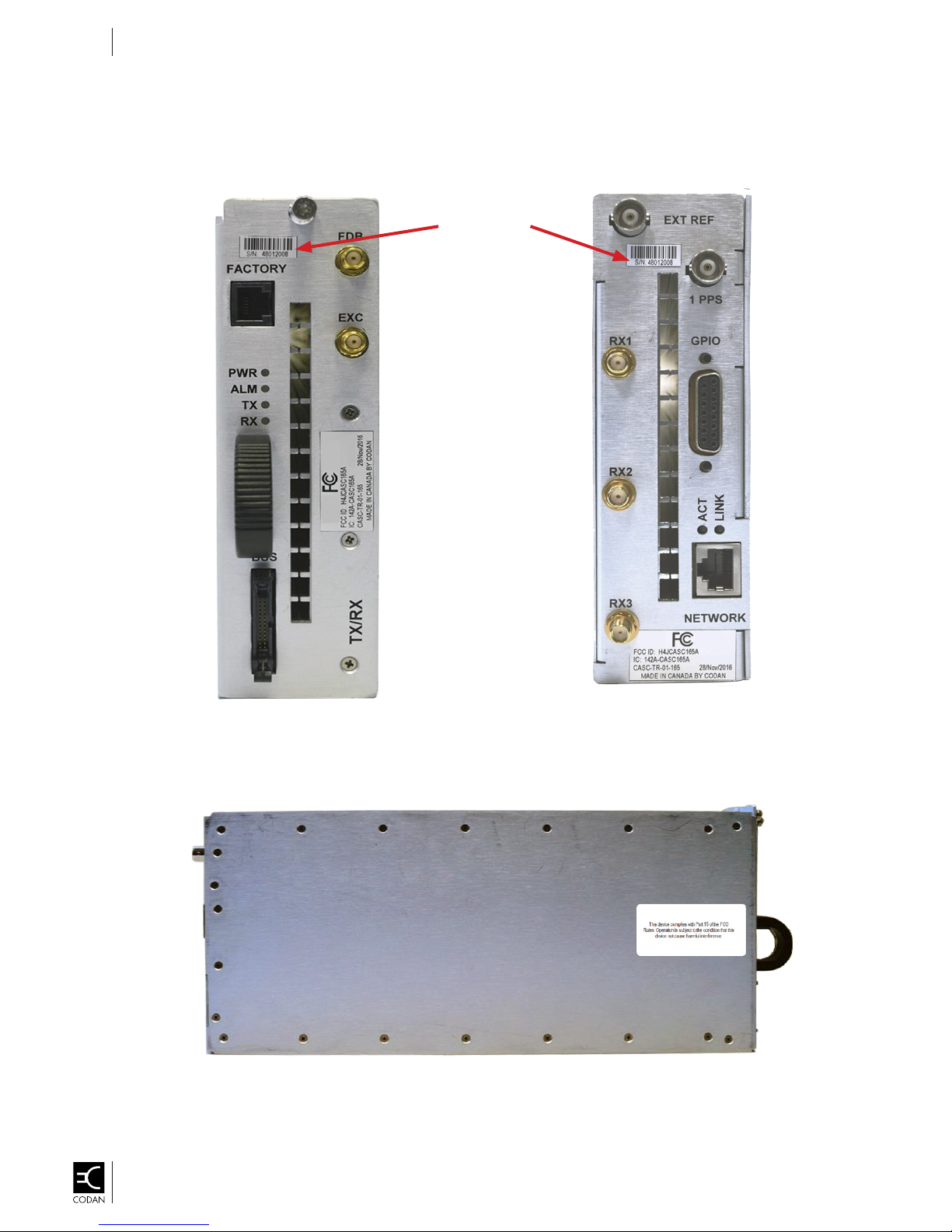
TRANSCEIVER LABELS
Transceiver – Front Transceiver – Rear
Serial Number
FCC ID
Left-Side – Part 15 FCC Label
FCC ID
Cascade System Modules Operation Guide
OG-CASC-SYS-MOD-1-0-0P
Page 41
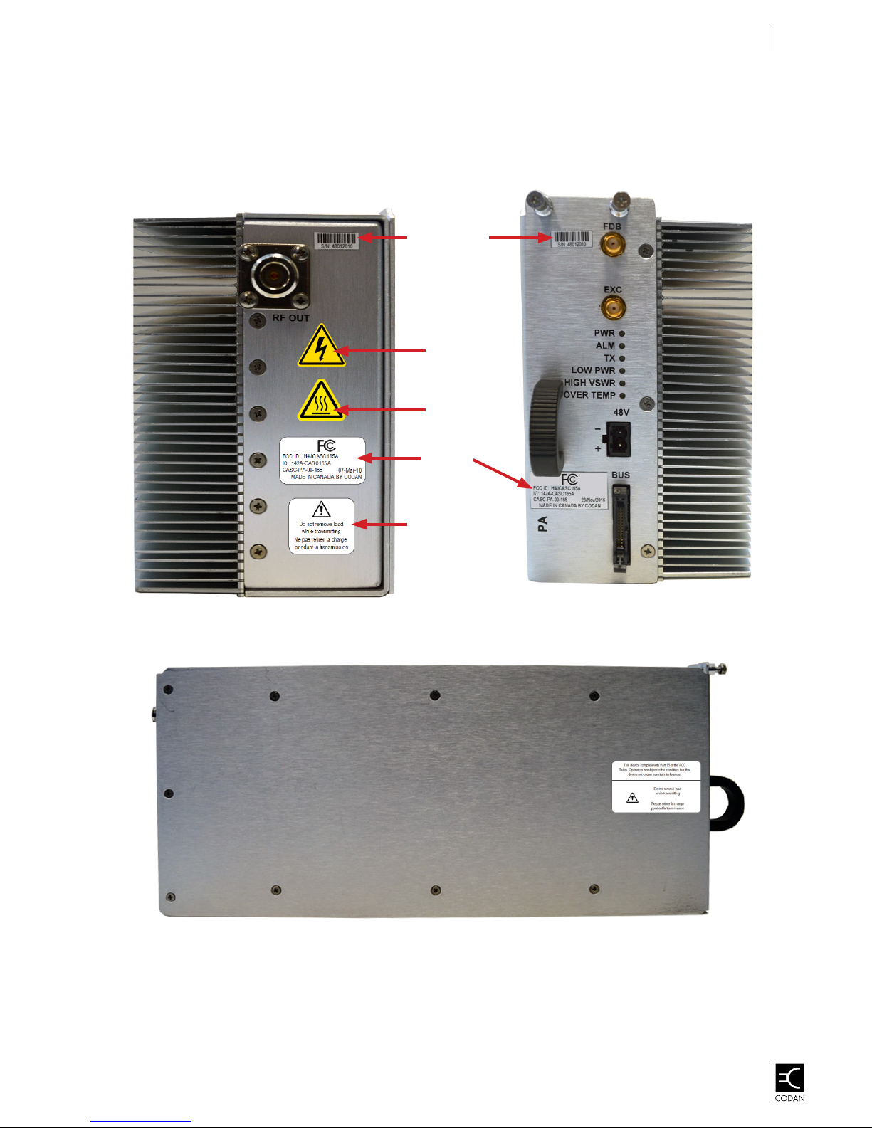
POWER AMPLIFIER LABELS
Serial Number
Electrical
Shock
Hot Surface
Product Labeling
41
FCC ID
Caution Label
Left-Side – Part 15 FCC Label
Cascade System Modules Operation Guide
OG-CASC-SYS-MOD-1-0-0P
Page 42
Product Labeling
42
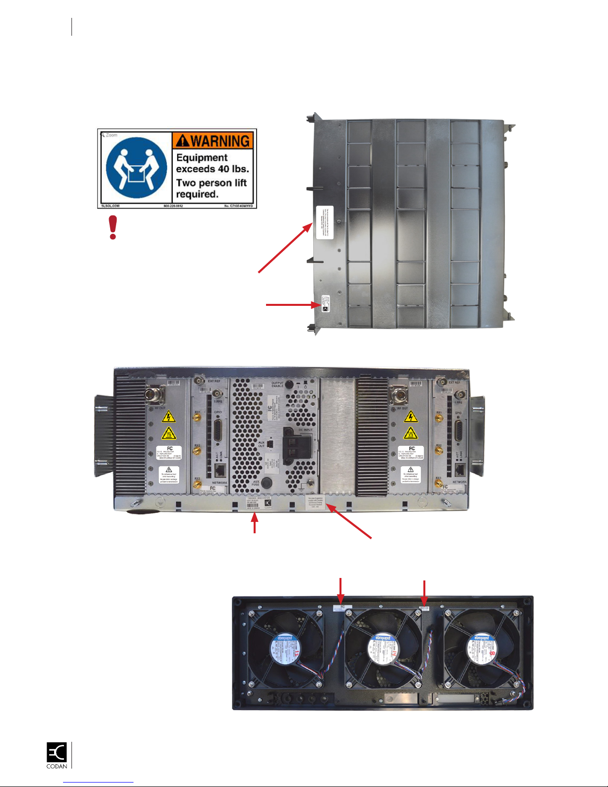
FRONT PANEL AND SUBRACK LABELS
Subrack – Top View
NOTE:
This warning label will be applied
to the product before shipping.
Class A – ICES
Product ID &
Serial Number
Subrack – Rear View
Product ID &
Serial Number
Class A – ICES
FCC ID
Serial Number
Front Panel –
Rear View
Cascade System Modules Operation Guide
OG-CASC-SYS-MOD-1-0-0P
Page 43

GLOSSARY OF TERMS
AM Amplitude Modulation
ANSI American National Standards Institute
CAP Compliance Assessment Program
CISPR Comité International Spécial des Perturbations Radioélectriques
International Special Committee on Radio Interference
EN European Committee for Standardization
ETSI European Telecommunications Standards Institute
EUT Equipment Under Test
FCC Federal Communications Commission
FM Frequency Modulation
FP Front Panel
HW Hardware
IEC International Electrotechnical Commission
IC Industry Canada
LED Light Emitting Diode
LSM Linear Simulcast Modulation
MU Measurement Uncertainty
PA Power Amplier
pk–pk Peak to Peak
PSU Power Supply
PTT Push To Talk
VSWR Voltage Standing Wave Ratio
43
Cascade System Modules Operation Guide
OG-CASC-SYS-MOD-1-0-0P
Page 44

This Page Intentionally Left Blank
44
Cascade System Modules Operation Guide
OG-CASC-SYS-MOD-1-0-0P
 Loading...