

Page 1

9390 Reference manual
Page 2

No part of this handbook may be reproduced,
transcribed, translated into any language or transmitted
in any form whatsoever without the prior written
consent of Codan Pty Ltd.
© Copyright 1996 Codan Pty Ltd.
Codan part number 15-04069 Issue 1, May 1996
Page 3

9390 Reference manual i
Contents
1 About this manual
Standards and icons...........................................................1-3
Glossary ............................................................................1-4
Other documents ...............................................................1-6
2 Installation
Type of station........................................................................2-2
Coast station......................................................................2-2
Ship station........................................................................2-3
Installing the transceiver.........................................................2-5
Mounting the cradle, gimbals and transceiver...................2-5
Installing the control head.......................................................2-7
Mounting the cradle and control head...............................2-7
Connecting the control head..............................................2-8
Power supply ........................................................................2-10
Mains operated supply ....................................................2-10
Battery supply .................................................................2-10
DC power cable...............................................................2-10
Grounding—RF earth...........................................................2-12
Ship stations....................................................................2-12
Coast stations ..................................................................2-14
9390 transceiver and control head grounding .................2-15
Ancillary equipment..............................................................2-16
Antennas and antenna tuners...........................................2-16
Page 4

Contents
ii 9390 Reference manual
3 Channel and scan table setup
Customising channels .............................................................3-2
Channel settings................................................................3-2
Changing channel settings.................................................3-3
Copying a channel to a new channel number..........................3-4
Changing a channel comment.................................................3-6
Changing channel options.......................................................3-8
Changing the receive frequency of a channel .......................3-11
Creating a receive-only channel............................................3-13
Creating a receive-only channel in Free-Tune
Receiver mode......................................................................3-16
Deleting a channel ................................................................3-19
Creating a transmit channel (option).....................................3-21
Creating a scan table.............................................................3-24
Deleting a scan table.............................................................3-29
Creating a telephone directory (option)................................3-31
4 Using Setup mode
Using Setup mode...................................................................4-2
List of Setup mode procedures ...............................................4-3
Advanced users.......................................................................4-7
5 Setup procedures (part 1)
ALE option settings (option) ..................................................5-2
Changing an ALE option setting.......................................5-7
ALE option reset (option).......................................................5-9
ALE sounding interval (option)............................................5-11
Beep loudness.......................................................................5-13
Call preamble length (option)...............................................5-15
Call privacy on/off (option)..................................................5-17
Clock calibration...................................................................5-19
Clock setting.........................................................................5-21
Clone a transceiver ...............................................................5-26
Page 5

Contents
9390 Reference manual iii
6 Setup procedures (part 2)
Display brightness...................................................................6-2
Display contrast......................................................................6-4
Display frequency...................................................................6-6
Free-Tune Receiver mode availability on/off .........................6-9
GPS display on/off (option)..................................................6-11
GPS timeout on/off (option) .................................................6-13
7 Setup procedures (part 3)
Password entry to enable transceiver options .........................7-2
Enabling transceiver options.............................................7-2
Deleting a PIN...................................................................7-6
Power up message on/off........................................................7-8
Power up mute setting...........................................................7-11
Power up selcall self ID display on/off (option)...................7-14
PTT release beep on/off........................................................7-16
PTT transmit cutout..............................................................7-18
Recall channels by frequency on/off.....................................7-20
RF gain on/off.......................................................................7-22
RS-232 connected equipment...............................................7-24
RS-232 connection baud rate................................................7-27
8 Setup procedures (part 4)
Scan table automatic scanning start ........................................8-2
Scan table editing on/off.........................................................8-4
Selcall ID setup (option).........................................................8-6
Setting up a selcall group..................................................8-7
Selcall ID size compatibility (option)...................................8-13
Selcall lockout on/off (option)..............................................8-16
Selcall mute availability on/off (option) ...............................8-19
Telcall availability on/off (option)........................................8-21
Tone call setup......................................................................8-23
99-beacon call response on/off (option) ...............................8-26
Page 6

Contents
iv 9390 Reference manual
9 Link Setup mode
Link Setup mode enter/exit.....................................................9-2
Antenna band or channel control............................................9-5
PIN setup................................................................................9-7
Setup mode availability on/off..............................................9-10
Transceiver reset to factory settings .....................................9-12
10 Display messages
11 Appendix
Connectors............................................................................11-2
Microphone socket..........................................................11-3
Antenna Control connector .............................................11-4
Remote Control connector ..............................................11-5
GP connector...................................................................11-6
RS-232 socket.................................................................11-7
Loudspeaker socket.........................................................11-7
External alarm socket......................................................11-7
Connecting ancillary equipment ...........................................11-8
Using the optional RS-232/I
2
C Interface............................11-10
Setting up the RS-232/I
2
C Interface..............................11-11
Specifications......................................................................11-14
Transceiver options.............................................................11-15
Accessories.........................................................................11-16
Index
Page 7

Contents
9390 Reference manual v
Figures
Figure 2.1 A typical coast station installation......................2-2
Figure 2.2 A typical ship station installation .......................2-3
Figure 2.3 High power ship station installation (24 volt) ....2-4
Figure 2.4 Rear view of control head without cover plate...2-8
Figure 2.5 General grounding requirements for metal
hulled vessels....................................................2-12
Figure 2.6 General grounding requirements for wooden or
fibreglass hulled vessels ...................................2-13
Figure 2.7 General grounding requirements for 9390-H
receive-exciters—all hull types ........................2-14
Figure 4.1 The Setup mode tree...........................................4-8
Figure 9.1 Moving the link for Link Setup mode ................9-2
Page 8

Contents
vi 9390 Reference manual
Page 9

9390 Reference manual 1-1
1 About this manual
This manual describes how you set up the Codan 9390 HF
SSB transceiver or the Codan 9390-H receiver-exciter.
This issue of the manual incorporates operating information
for software versions:
• transceiver 3.02
• control head 3.01.
To check the version of your transceiver, refer to the User
guide, Chapter 4, Using View All Settings mode—transceiver
software issue.
You should refer to this manual when you want to:
• set up the transceiver for the first time
• change how the transceiver operates
• use options or ancillary equipment with the transceiver.
Page 10

About this manual
1-2 9390 Reference manual
The manual contains 11 chapters.
Chapter 1 explains how to use the manual.
Chapter 2 explains how to install your transceiver and
connect the components that make up your station.
Chapter 3 explains how to set up channels, scan tables and
the telephone directory.
Chapter 4 explains how to use Setup mode to set up how the
transceiver works. You should read this before following any
Setup mode procedure described in Chapters 5–8.
Chapters 5–8 describe the Setup mode procedures which
have been separated into four parts for ease of reference.
Chapter 9 describes Link Setup mode procedures.
Chapter 10 lists all information and error messages output to
the transceiver display.
Chapter 11 covers technical information such as the
connector pin arrangements, ancillary equipment settings,
transceiver specifications, options and accessories.
We recommend that only Codan approved service agents
perform maintenance on the transceiver.
Page 11
About this manual
9390 Reference manual 1-3
Standards and icons
In this manual, Arial typeface in single quotes is used for text
shown on the transceiver display. For example:
If ‘
no response
’ was displayed, send the call again.
Arial typeface in bold is used for the names of buttons, knobs
and connectors. For example:
Press the
On/Off
button.
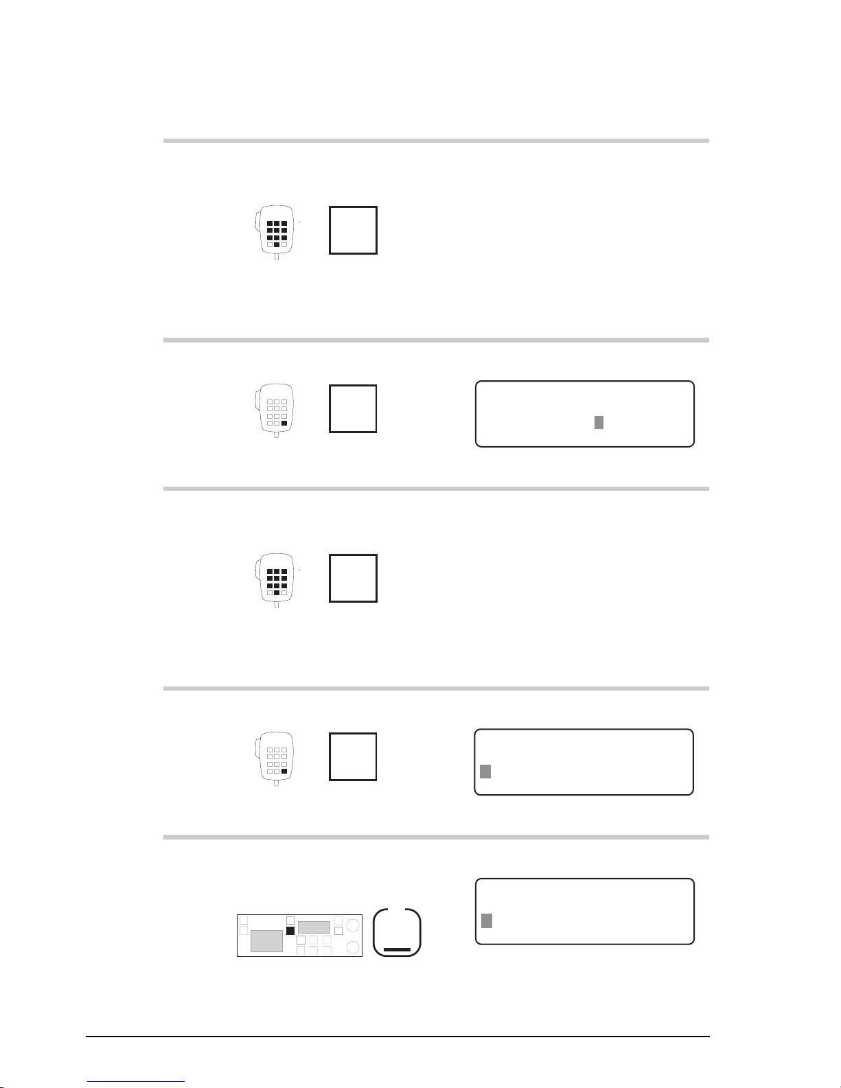
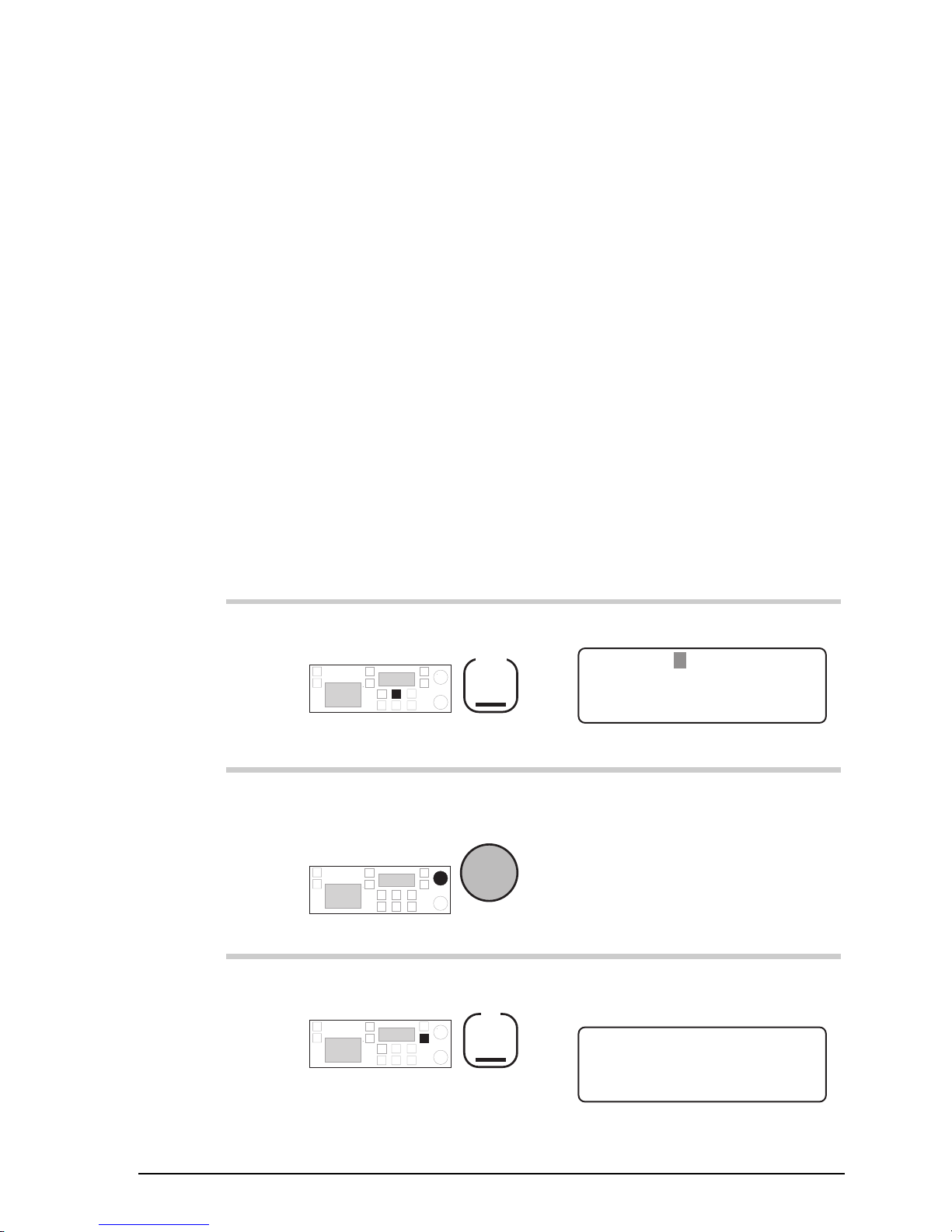
This icon... Means...
the end of a subject.
a warning.
On/Off
the transceiver button or knob
that you need to operate (the
On/Off
button in this example).
The solid area in the picture of
the transceiver control panel on
the left shows you where to find
the button or knob.
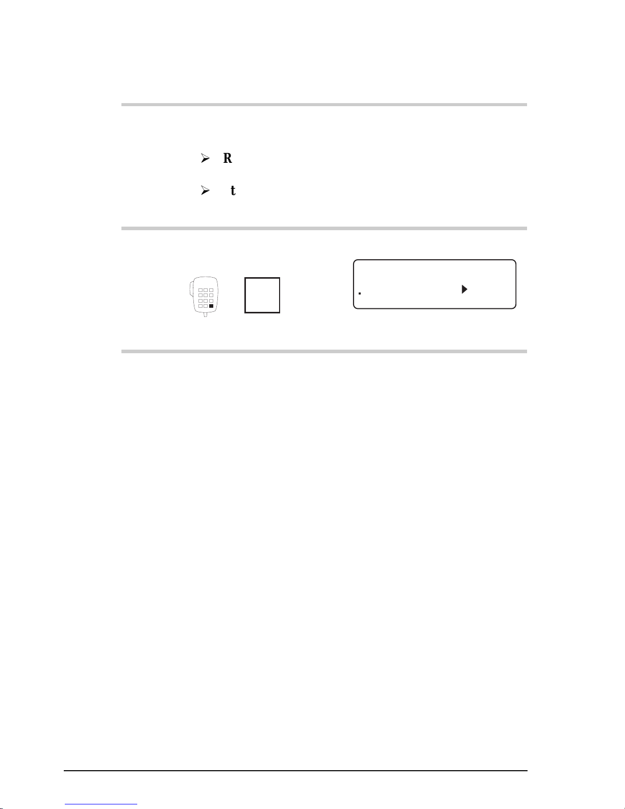
Call
the microphone button that you
need to operate (the
Call
button
in this example). The solid area
in the picture of the microphone
on the left shows you where to
find the button.
Page 12

About this manual
1-4 9390 Reference manual
Glossary
This term... Means...
ALE Automatic Link Establishment.
AM Amplitude Modulation.
Call memory a list containing details of the last ten calls
you have received.
Called ID the ID of the station being called (the
receiving station’s self ID).
EPROM Erasable Programmable Read-Only
Memory.
GPS Global Positioning System.
HF High Frequency.
LCD Liquid Crystal Display.
LSB Lower Sideband.
LU Lower/Upper Sideband.
PCB Printed Circuit Board.
PIN Personal Identification Number.
PSTN Public Switched Telephone Network.
PTT
button
Press-To-Talk button.
RDD Radio Direct Dial.
Receive-only
channel
a channel that allows you to receive calls
but not send calls.
Receiver-exciter a version of the transceiver designed to
operate with an external high power RF
amplifier (400 watts PEP).
Revertive signal an acknowledgment signal automatically
transmitted from a station receiving a call.
RF Radio Frequency.
Rx Receive.
Page 13

About this manual
9390 Reference manual 1-5
This term... Means...
Scan table a list of channels used when scanning for
incoming calls.
Selcall the simplest type of selective call.
Selective calling a call to a specific station (transceiver
option). Selective calls include beacon
calls, selcalls, telcalls, GPS calls, page
calls and ALE calls.
Self ID the programmed address identification
number of your station. (Used by other
stations to call you.)
SSB Single Sideband transmission format.
Transceiver-exciter a version of the transceiver designed to
operate with an external high power RF
amplifier (400 watts PEP).
Transceiver ID a unique, factory programmed 16-
character alpha-numeric identification
code.
Transmit channel a channel that allows you to receive and
transmit calls.
Two-frequency
simplex
a channel that has different transmit and
receive frequencies but does not allow
simultaneous send and receive.
Tx Transmit.
TXE Transmit Enabled. To enable user
programming of transmit frequency.
USB Upper Sideband.
Page 14

About this manual
1-6 9390 Reference manual
Other documents
For information on how you use the transceiver to send and
receive calls, refer to the 9390 User guide (Codan part
number 15-04068).
For information on ALE calling, refer to the 9300 ALE
controller user guide (Codan part number 15-04046).
Page 15

9390 Reference manual 2-1
2 Installation
This chapter describes how to install your transceiver and
connect the components that make up your station.
It covers:
• type of station (2-2)
• installing the transceiver (2-5)
• installing the control head (2-7)
• power supply (2-10)
• grounding—RF earth (2-12)
• ancillary equipment (2-16).
On receipt of your transceiver, check the contents against the
packing list. Ensure all items are available before starting
installation.
The procedures for installing your transceiver are not
comprehensive. They are to be used as a guide only. We
recommend that installation be carried out by qualified and
experienced personnel.
Page 16
Installation
2-2 9390 Reference manual
Type of station
You can operate the transceiver from more than one place if
you attach control heads to your system. Control heads have
the same control panel as the transceiver. The smaller depth
of the control head allows you to mount the unit where there
is insufficient space for the transceiver.
There are two types of station:
• coast station
• ship station.
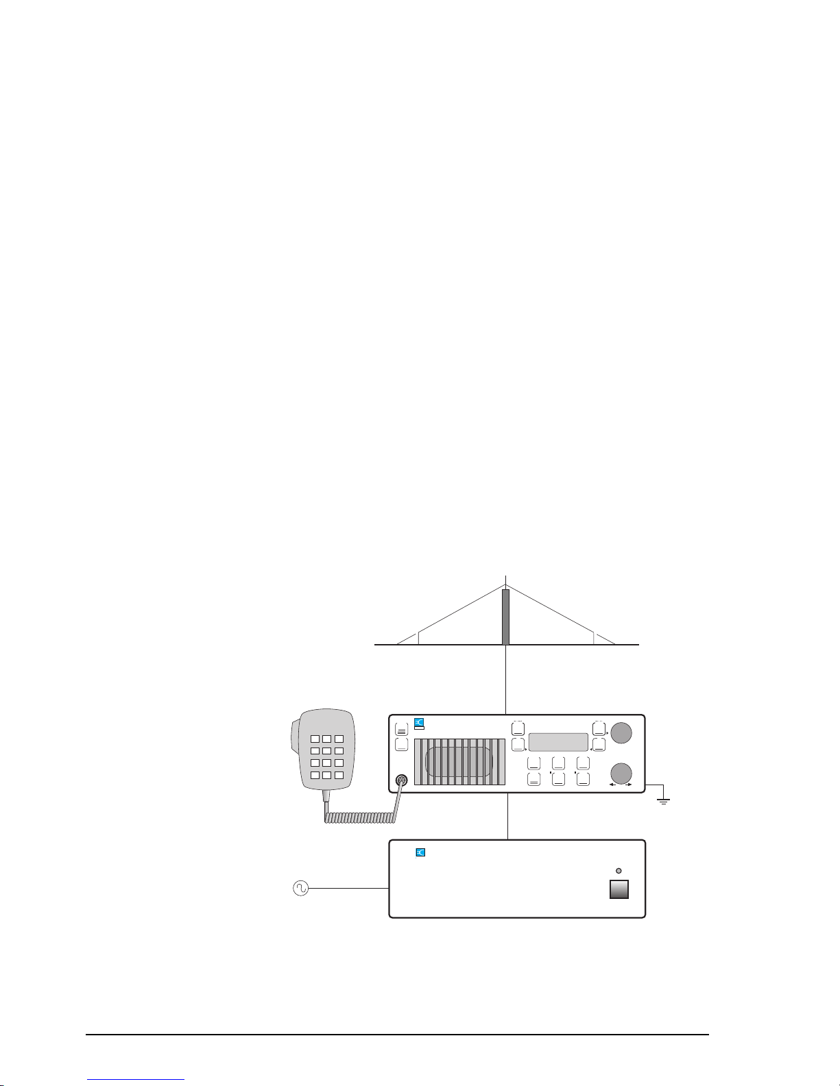
Coast station
A fixed base coast station typically consists of an AC power
supply connected directly to the mains. DC output from the
power supply is connected to the transceiver which, in turn, is
connected to an antenna system.
AC power supply
Coaxial cable
Microphone
Earth point
Transceiver
On/Off
Select
Mode
Scan
S'Call
Mute
Voice
Mute
On/Off Mode
Tune
F2F1
Volume
9390 Marine Transceiver
CODAN
Test
2182
AM /SSB
Emgcy
Call
Broadband antenna
system
AC mains
XXXX Power Supply
CODAN
Figure 2.1
A typical coast station installation
Page 17
Installation
9390 Reference manual 2-3
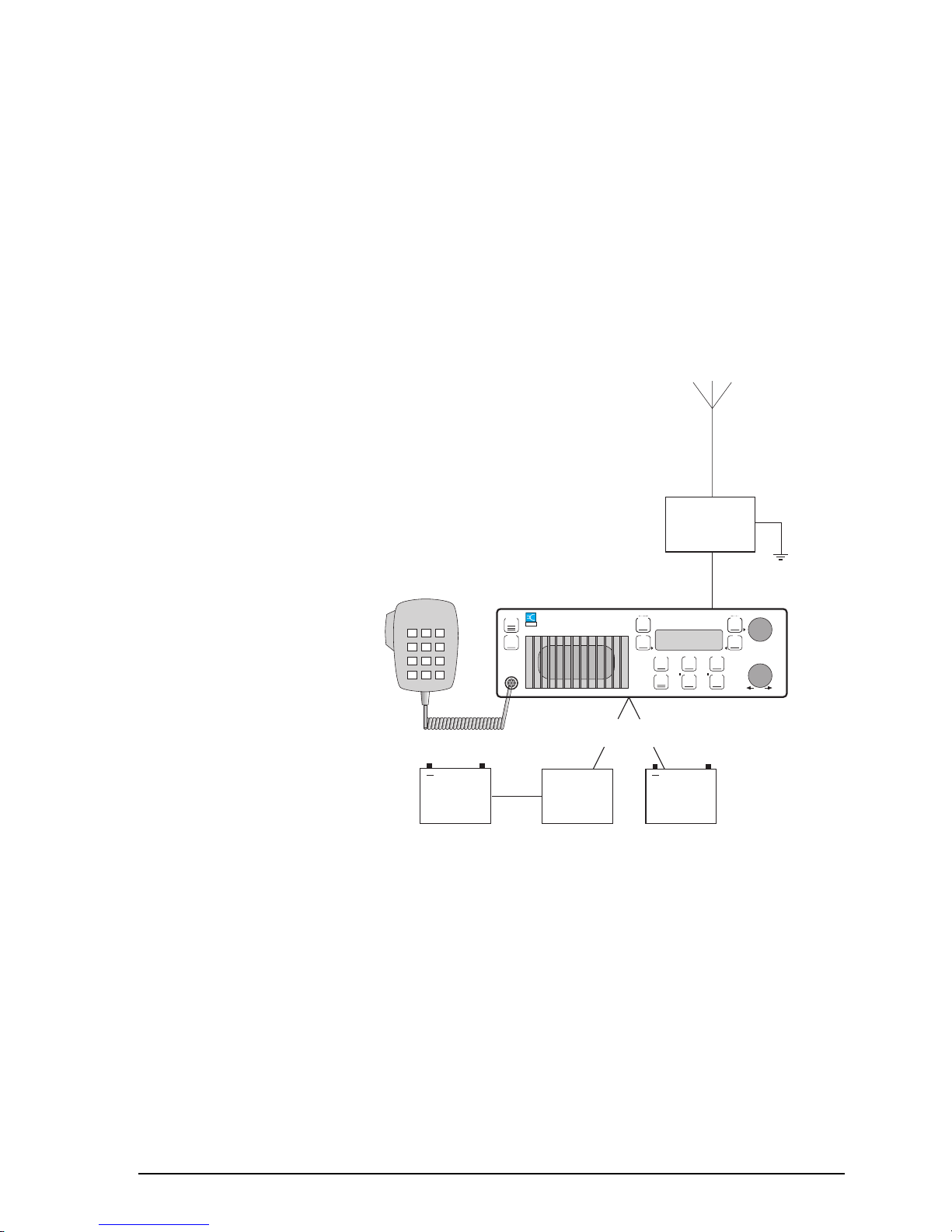
Ship station
A ship station typically consists of a DC power supply
(battery) connected to the transceiver. A coaxial cable
connects the transceiver to an antenna tuning unit which is
attached to a whip or long wire antenna.
The transceiver and microphone should be mounted in such a
way as to be easily accessible to the operator.
24V to
12V
inverter
Microphone
Transceiver
Whip or long
wire antenna
On/Off
Select
Mode
Scan
S'Call
Mute
Voice
Mute
On/Off Mode
Tune
F2F1
Volume
9390 Marine Transceiver
CODAN
Test
2182
AM /SSB
Emgcy
Call
+
24V
battery
either / or
+
12V
battery
9103 or 4203
antenna
tuner
Figure 2.2
A typical ship station installation
Page 18
Installation
2-4 9390 Reference manual
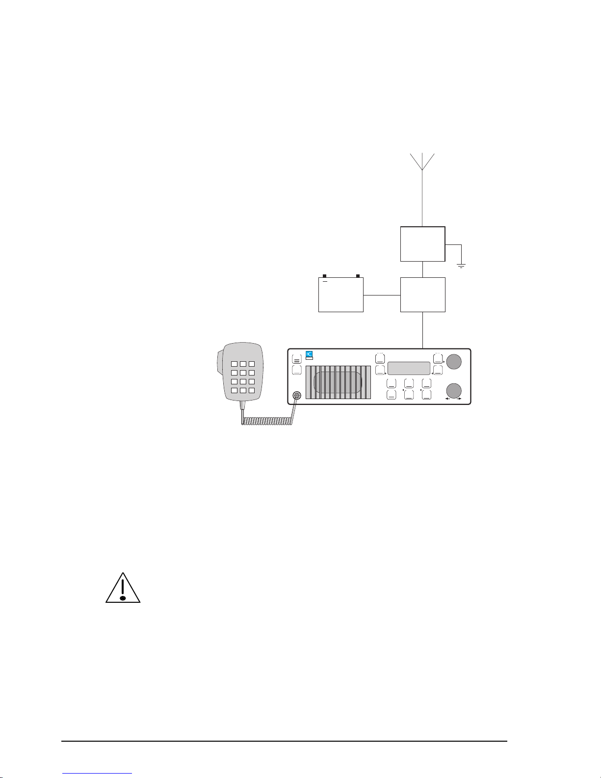
For 400 watt high power systems using a 9390-H receiverexciter, an external PA unit is connected between the
receiver-exciter and the antenna tuning unit.
Microphone
9390-H receiver-exciter
On/Off
Select
Mode
Scan
S'Call
Mute
Voice
Mute
On/Off Mode
Tune
F2F1
Volume
9390 Marine Transceiver
CODAN
Test
2182
AM /SSB
Emgcy
Call
Whip or long
wire antenna
4203
antenna
tuner
400 watt
PA type
4404
+
24V
battery
Figure 2.3
High power ship station installation (24 volt)
Where cables must pass through bulkheads with sharp edges,
the insulation of the cables should be protected by grommets.
Holes in the bulkhead need only be large enough to allow the
end of the cable with the smaller connector to pass through
(for example, the control cable between the control head and
the transceiver).
If the power and control cables are long and follow a common
path, keep the cables separated by at least 200mm. The cables
can be closer together for short distances, for example, to pass
through the same hole in the bulkhead.
Failure to observe this warning can cause distortion of the
transmitted audio signals.
Page 19

Installation
9390 Reference manual 2-5
Installing the transceiver
The transceiver must be mounted in a position that:
•
allows easy access to the controls
•
allows a free flow of air through the rear cooling fins
•
is not exposed to direct sunlight
•
will not cause injury in the event of rough conditions or an
accident.
Mounting the cradle, gimbals and transceiver
The cradle and gimbals for mounting the transceiver are
suitable for locations where there is enough space available
to slide the transceiver in and out.
The cradle provides DC isolation for the transceiver.
To mount the cradle, gimbals and transceiver:
1. Assemble the supplied pair of mounting gimbals onto the
cradle in the position and angle that provides good access
to the mounted transceiver controls. Two fixing bolts
(M5 x 8mm) for each gimbal are supplied.
2. Secure the cradle in position with the rotating cam
catches to the front. Ensure there is sufficient space at the
rear of the cradle to clear the transceiver heat sink and
connectors.
3. Align both cam catch slots with the T-section slides.
Cam catch
(Slot in line
with T slide)
Front section
Page 20

Installation
2-6 9390 Reference manual
4. Insert the transceiver side rails into the T-section slides
and push the transceiver fully into the cradle.
5. Apply gentle pressure to the front of the transceiver and
lock it into the cradle by using a flat blade screwdriver to
turn the cam catches one quarter of a turn in either
direction.
Page 21

Installation
9390 Reference manual 2-7
Installing the control head
Make sure that the transceiver is disconnected from the DC
power source before connecting the control head to the
Remote Control
connector on the transceiver.
Mounting the cradle and control head
To mount the cradle and control head:
1. Select a suitable location to mount the control head.
Avoid places exposed to direct sunlight.
2. Remove the two cradle screws and washers securing the
cradle to the control head.
3. Secure the cradle into position. Ensure that there is
sufficient space at the rear for the cables.
4. Secure the control head to the cradle with the two screws
and washers.
Page 22
Installation
2-8 9390 Reference manual
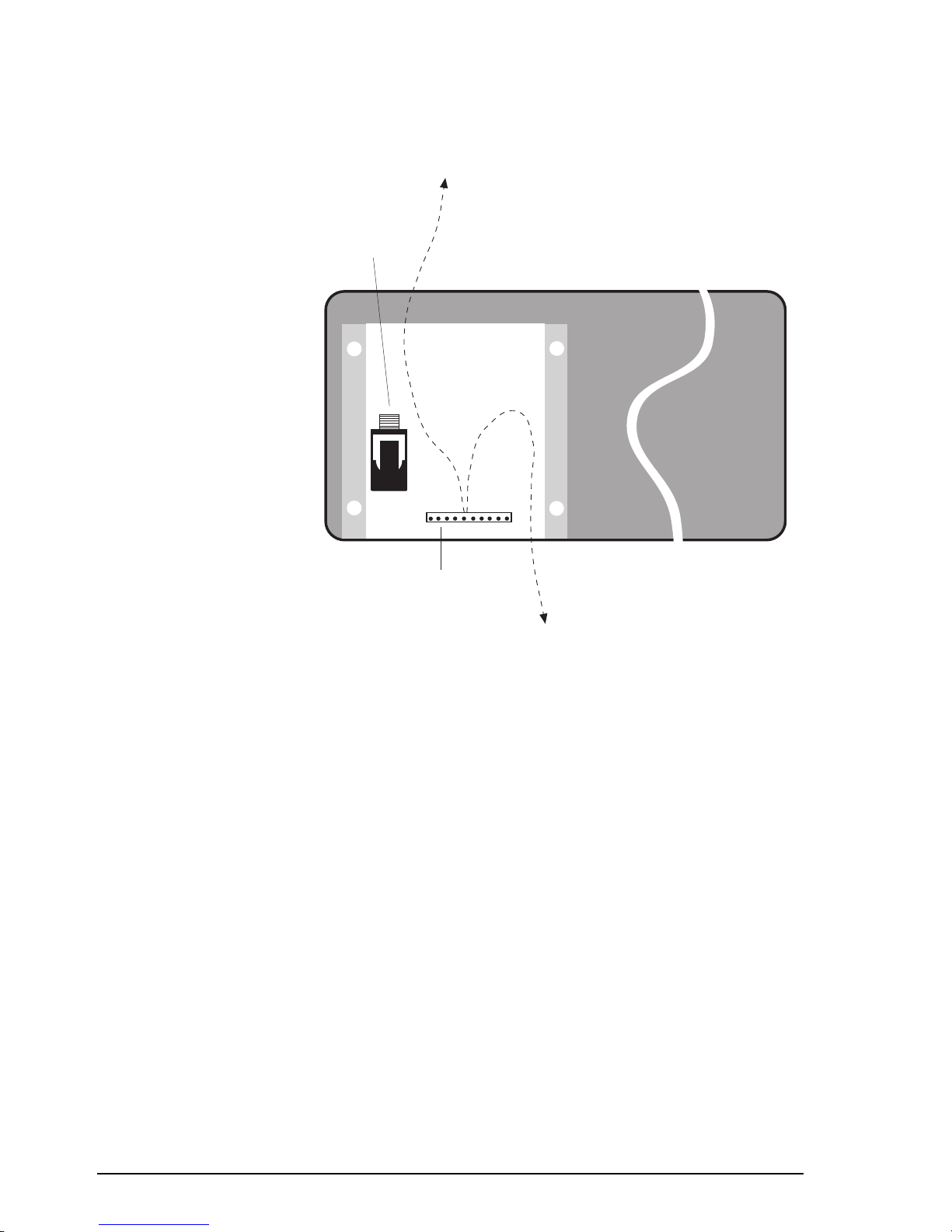
Connecting the control head
L/S
(extension
loudspeaker)
socket
10-pin control cable
connector
Bottom entry
cable path
Top entry
cable path
Figure 2.4
Rear view of control head without cover
plate
The control head chassis is isolated from ground but in
operation may require earthing. See Grounding—RF earth on
page 2-12.
To connect the control head:
1. Remove the four screws that secure the small cover plate
at the back of the control head. Remove the cover. Figure
2.4 shows the back of the control head with the cover
plate removed.
2. If you are connecting an extension loudspeaker, feed the
loudspeaker cable through the foam grommet near the
control head end of the control cable. Note that the
transceiver also has provision for connecting the
extension loudspeaker.
3. Use the cable clamp to attach the control cable to the
inside surface of the cover.
Page 23

Installation
9390 Reference manual 2-9
4. Plug the control cable into the 10-pin connector (the
cable only fits one way).
5. If you are connecting an extension loudspeaker, plug the
loudspeaker cable into the
L/S
(extension loudspeaker)
socket.
6. Insert the foam grommet into the slot on the cover plate.
7. The cover plate can be rotated to give you either top or
bottom cable entry. Replace the cover plate and secure it
with the four screws.
8. Make sure that the transceiver is disconnected from the
DC power source.
9. Plug the control cable into the
Remote Control
connector on the rear panel of the transceiver. Fasten the
cable securely.
10. Plug in the microphone by gently rotating the plug in the
microphone socket until the pins locate. Push the plug
home and fasten the locking ring until finger-tight. Do
not over tighten.
11. If the 6-metre control cable is too long, gather the excess
neatly and secure it out of the way. Do not cut the cable.
Make sure that the transceiver is disconnected from the DC
power source before connecting the control head to the
Remote Control
connector on the transceiver.
Page 24

Installation
2-10 9390 Reference manual
Power supply
Ensure that the power supply and power cable for the
transceiver is suitable for correct and safe system operation.
For both 12V and 24V DC systems the power source can be
mains operated or battery.
Mains operated supply
We recommend the Codan AC power supply 9113 or 9114
for 12V DC operated 9390 front or extended control
transceivers. The 9114 is necessary if you are going to use
your transceiver for fax or data transmissions.
We recommend the heavy duty AC power supply accessory
code 507 for 24V DC operated systems using the 9390-H
receiver-exciter and the PA type 4404.
Battery supply
You can use standard, heavy duty 12V or 24V batteries as the
system supply. If a 12V system has to be powered from a
24V battery, install the accessory code 508 voltage regulator
(12V) within two metres of the transceiver.
DC power cable
It is important that the size of the DC power cable (cross
sectional area) is sufficient to keep the voltage drop between
power source and transceiver within close limits.
To check the effectiveness of the power cable installation
with the tuner and antenna connected, press the
Tune
button
and measure the voltage at the transceiver end of the cable.
The voltage should not drop more than 0.5V compared with
the voltage on receive only.
Page 25
Installation
9390 Reference manual 2-11
9390 front and extended control 12V systems are supplied
with 6-metre power cables. 9390-H receiver-exciter 24V 400
watt systems are supplied with 2-metre power cables. If a
supplied cable is too short, a larger cable size must be used
replacing the existing cable. Refer to the following table.
Maximum
distance from
power source
12V system cable
size
24V 400 watt
system cable size
6 metres Use supplied cable 16mm2 (7/1.7mm)
9 metres 16mm2 (7/1.7mm) 25mm2 (19/1.35mm)
18 metres 25mm2 (19/1.35mm) 50mm2 (19/1.78mm)
Protect all cables from sharp edges and mechanical abrasion.
We recommend that you fit a suitable cartridge fuse in the
active wire close to the battery or main isolating switch. This
protects the power cable and your vessel from risk of fire
should damaged insulation cause a short circuit. Use a 32A
fuse for a 12V system (accessory code 711) or a 50A fuse for
a 24V, 400 watt system. Do not use normal glass in-line
automotive fuses as these cause too high a voltage drop
during transmission.
A qualified technician should check your installation before
power is applied to the transceiver.
In extended control installations where the power and control
cables are long and follow a common path, keep the cables
separated by at least 200mm. The cables can be closer
together for short distances, for example, to pass through the
same hole in the bulkhead.
Failure to observe this warning can cause distortion of the
transmitted audio signals.
Page 26

Installation
2-12 9390 Reference manual
Grounding—RF earth
A good ground (RF earth) is essential for efficient operation
of the installed transceiver system.
This section is a general guide for achieving the best
performance from your installation. For maximum reliability
and safety, we recommend that you also seek expert advice
specific to your installation.
Inappropriate earthing can result in severe damage to your
vessel through electrolytic corrosion.
The chassis and earth point of the 9390 transceiver are
connected to the negative supply. The 9390-H receiverexciter, control head, PA type 4404, code 733B Aerial DC
Isolator and antenna tuners have isolated earth points.
Ship stations
A metal hulled vessel in salt water provides an almost ideal
ground. Connect the tuner and any other equipment requiring
an earth to the hull using the shortest possible ground strap.
To minimise contact resistance, use a large, clean and paintfree contact area.
Antenna
9103 or 4203
antenna
tuner
Code
733B (as
required)
9390
transceiver
Control
head
Do not earth the transceiver
Connect earth points directly to
the metal hull
Figure 2.5
General grounding requirements for metal
hulled vessels
Page 27

Installation
9390 Reference manual 2-13
Wooden or fibreglass hulled vessels present more of a
grounding problem. Use bonding straps to connect the
antenna tuner and all other earth points directly to a radio
earth plate attached to the outside of the hull below the water
line.
Antenna
9103 or 4203
antenna
tuner
9390
transceiver
Control
head
Do not earth the transceiver
Connect earth points to one or
more radio earth plates using
copper bonding straps
Earth plates may
be linked
Code
733B (as
required)
Figure 2.6
General grounding requirements for wooden
or fibreglass hulled vessels
The earth plate may be a 1mm thick copper sheet of at least
0.25 square metres or an E-plate, such as accessory code 157.
Multiple earth plates may be an advantage.
Bonding should be with 25–50mm wide copper straps for
lengths up to two metres. Use proportionately wider or
multiple straps for longer runs. A thickness of 0.5mm is
sufficient since the RF current only flows on the conductor
surface. Alternatively, you can use 20mm diameter copper
tubing.
Run one or more bonding straps from the earth plate to the
antenna tuner. Where possible, joints should be brazed and
inspected regularly for corrosion.
Page 28

Installation
2-14 9390 Reference manual
The general grounding requirements for 9390-H receiverexciter systems are the same for all hull types.
Antenna
9103 or 4203
antenna
tuner
400 watt
PA type
4404
9390-H
receiverexciter
Control
head
Figure 2.7
General grounding requirements for 9390-H
receive-exciters—all hull types
Coast stations
For typical coast station installations (see Figure 2.1 on page
2-2) we recommend that you earth the chassis ground point of
the transceiver.
You can establish an effective ground with an earthing spike
or water pipe that has good soil contact and is free of joints
that could increase the path resistance to earth. Use copper
braid of at least 12mm wide for the connection.
Page 29

Installation
9390 Reference manual 2-15
9390 transceiver and control head grounding
Grounding the 9390 transceiver or control head is
unnecessary for most installations. If RF interference causes
transmit distortion, you may need to ground either or both
units.
The transceiver chassis is connected to battery negative and
will be DC isolated from ground when installed with the
cradle (see Installing the transceiver on page 2-5).
If the transceiver needs to be grounded, use a code 733B
Aerial DC Isolator to isolate the transceiver when connecting
to the antenna tuner and the RF earth point.
To earth the control head, earth the mounting bracket by
ensuring that the screws holding the mounting bracket are not
insulated. It may be necessary to remove paint from around
the screws to ensure a good contact.
Page 30

Installation
2-16 9390 Reference manual
Ancillary equipment
There is a range of ancillary equipment you can connect to
the transceiver. For details, see Chapter 11, Connecting
ancillary equipment.
Antennas and antenna tuners
Correct installation of the antenna and antenna tuner is
important for good transceiver operation.
To obtain the best performance and good radiation efficiency
from your transceiver, consider the antenna and antenna
tuner’s:
• physical location
• distance from the transceiver
• grounding.
Follow the installation instructions provided with each
antenna and antenna tuner to achieve the best possible
performance.
Page 31

9390 Reference manual 3-1
3 Channel and scan table setup
This chapter covers:
• customising channels (3-2)
• copying a channel to a new channel number (3-4)
• changing a channel comment (3-6)
• changing channel options (3-8)
• changing the receive frequency of a channel (3-11)
• creating a receive-only channel (3-13)
• creating a receive-only channel in Free-Tune Receiver
mode (3-16)
• deleting a channel (3-19)
• creating a transmit channel (option, 3-21)
• creating a scan table (3-24)
• deleting a scan table (3-29)
• creating a telephone directory (option, 3-31).
Page 32

Channel and scan table setup
3-2 9390 Reference manual
Customising channels
You can customise the way channels are set up in your
transceiver. For example, you might want to:
• change channel comments to help you remember how
channels are used
• copy regularly used channels to group them for
convenience (for example, creating a group of 10
channels with channel numbers 9001 to 9010).
Channel settings
Transmit channel settings consist of:
• frequency (either a single transmit/receive frequency or a
two-frequency simplex)
• sideband (upper and AM—lower/selectable needs local
authority approval)
• tone call group (1–4 or none)
• selcall group (option, 1–5 or none)
• channel protection (on/off)
• channel comment (description of channel).
Receive-only channel settings consist of:
• frequency
• sideband (upper/lower/selectable)
• channel protection (on/off)
• channel comment (description of channel).
When you send a call, the frequency and sideband have to be
the same for both stations. The channel number is
unimportant.
Page 33

Channel and scan table setup
9390 Reference manual 3-3
Changing channel settings
Factory fitted, standard marine channels consist of:
• protected channels
• Radphone channels.
If you want to change the settings of a protected channel,
make an unprotected copy of the channel and edit the copy.
You may then change any channel setting except for the
transmit frequency.
If your transceiver has option TXE, you can change the
setting of a protected channel including the transmit
frequency.
You can change Radphone channel options and comments
but not frequencies (even with TXE). To reset a Radphone
channel to its factory set condition, you delete the modified
version. You cannot delete factory set Radphone channels.
If you change the single transmit/receive frequency of a
transmit channel, the channel becomes a two-frequency
simplex with a new receive frequency. The transmit
frequency remains unchanged.
Page 34
Channel and scan table setup
3-4 9390 Reference manual
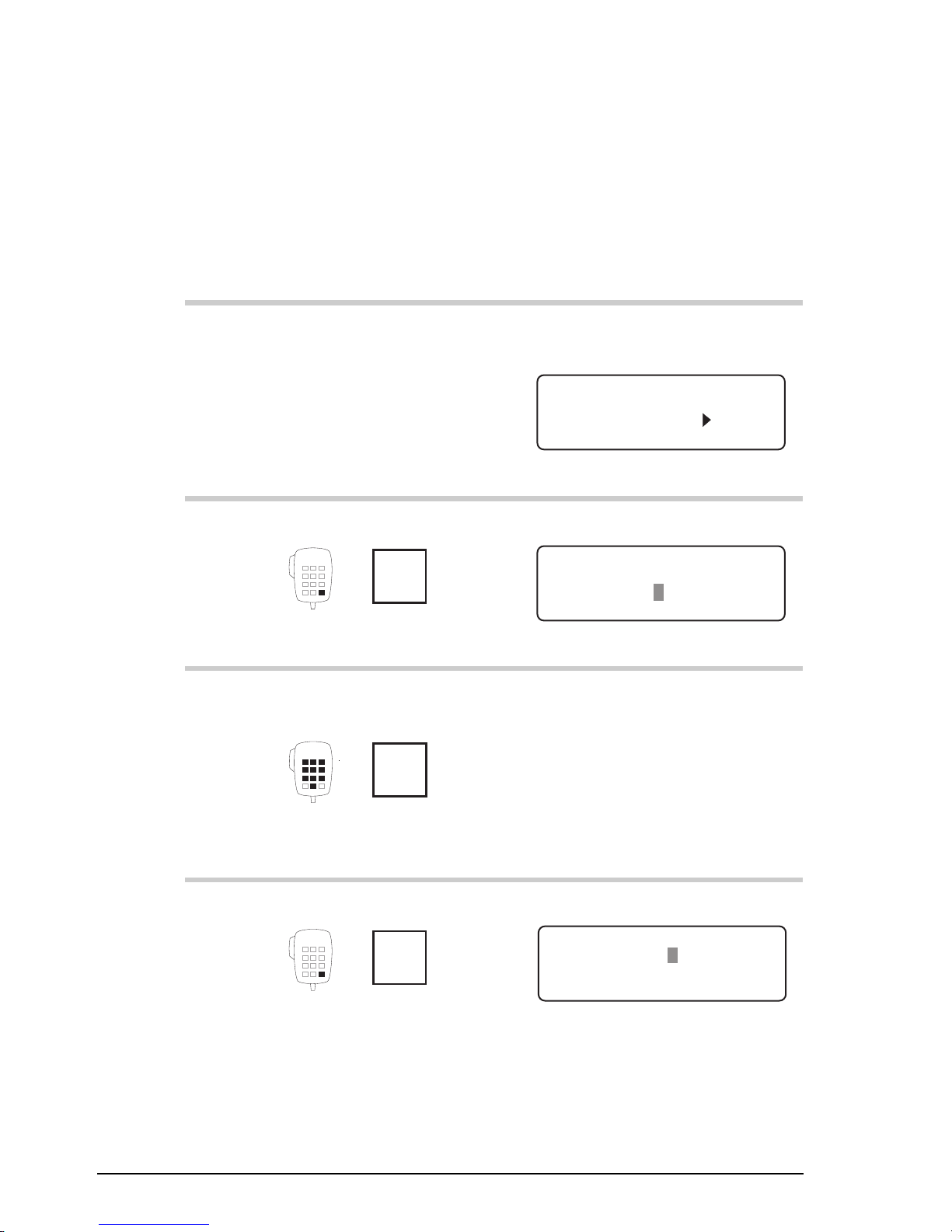
Copying a channel to a new channel number
To copy a channel to a new channel number:
Action Notes
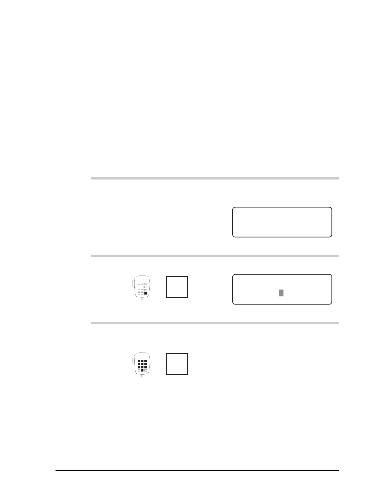
1.
In Channel mode, select
the channel that you want
to copy.
Example of the display for
channel 804:
USB
HI
RF–ON
Rx.
804
Radphone
Pwr
8,204
8,728
2.
Press twice
Enter
R'call
Example of the display:
DELETE
ENTER
Enter Channel No.
–804
3.
Enter the number of a
new, unused channel
numeral
buttons
For example, enter 9991 to
copy channel 804 to channel
9991.
4.
Press
Enter
R'call
Example of the display:
EXIT ENTER
Enter Receive Freq
RX 8,728.00
Page 35

Channel and scan table setup
9390 Reference manual 3-5
Action Notes
5.
To save the new channel,
press four times
Enter
R'call
The display shows the new
channel:
USB
HI
RF–ON
Rx.
9991
Radphone
Pwr
8,204
8,728
Page 36

Channel and scan table setup
3-6 9390 Reference manual
Changing a channel comment
To change a channel comment:
Action Notes
1.
In Channel mode, select
the channel that you want
to change.
Example of the display for
channel 9991:
USB
HI
RF–ON
Rx.
9991
Radphone
Pwr
8,204
8,728
2.
Repeatedly press
Enter
R'call
until you see ‘
Enter
channel text
’ displayed.
Example of the display:
CLEAR ENTER
Enter channel text
Radphone––––––––––––
3.
To clear any existing text,
press
F1
Example of the display:
CLEAR ENTER
Enter channel text
––––––––––––––––––––
Page 37

Channel and scan table setup
9390 Reference manual 3-7
Action Notes
4.
To enter a comment to
describe this channel,
rotate
Select
to select each character
and
Volume
to move along the line to
the next character
position.
Enter up to 20 characters (for
example, Trawler Network).
5.
To save your changes for
the channel, press
Enter
R'call
Example of the display:
USB
HI
RF–ON
Rx.
9991
Trawler Network
Pwr
8,204
8,728
Page 38

Channel and scan table setup
3-8 9390 Reference manual
Changing channel options
You cannot change the channel options of protected channels
(unless you have option TXE). If you want to change these
settings, make an unprotected copy of the channel and edit
the copy.
The table below lists which of the four channel options you
can change for each type of unprotected channel.
Transmit
channel
Receiveonly
channel
Radphone
channel
Sideband
Yes * Yes No
Tone call
group
Yes No Yes
Selcall
group
Yes No Yes
Channel
protection
Yes Yes No
* You need local authority approval to change the sideband
setting from USB.
Use caution when changing the channel protection option!
Once you protect a channel, only a Codan agent can change
or delete this channel without deleting many other channels
from the transceiver (unless you have option TXE).
Page 39
Channel and scan table setup
9390 Reference manual 3-9
To change channel options:
Action Notes
1.
In Channel mode, select
the channel that you want
to change.
Example of the display for
channel 9991:
USB
HI
RF–ON
Rx.
9991
Trawler Network
Pwr
8,204
8,728
2.
Repeatedly press
Enter
R'call
until you see ‘
Enter
Options
’ displayed.
Example of the display:
EXIT ENTER
Enter Options
Upper sideband
U T1 S1 NP
3.
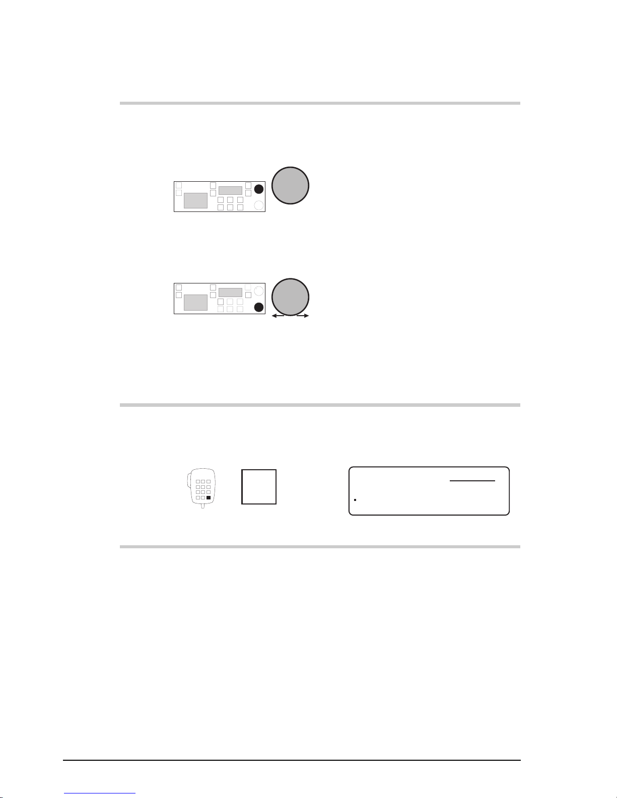
To move to the option
setting you want to
change, rotate
Volume
Example of the selcall group
setting:
EXIT
ENTER
Enter Options
Self Id: 2 2 4 7 Codan
U T1 S1 NP
4.
To change the setting,
rotate
Select
Selcalling is now disabled for
this channel:
EXIT
ENTER
Enter Options
Selcalls not enabled
U T1 S– NP
Page 40
Channel and scan table setup
3-10 9390 Reference manual
Action Notes
5.
Do you want to change
another option setting?
Yes
Return to
Step 3.
No
Step 6.
6.
To save your changes for
the channel, press twice
Enter
R'call
Example of the display:
USB
HI
RF–ON
Rx.
9991
Trawler Network
Pwr
8,204
8,728
Page 41
Channel and scan table setup
9390 Reference manual 3-11
Changing the receive frequency of a channel
Frequencies of protected channels (unless you have option
TXE) and Radphone channels cannot be changed. To change
the receive frequency of one of these channels, you copy the
channel and edit the copy.
To change the receive frequency of a protected or Radphone
channel:
Action Notes
1.
In Channel mode, select
the channel that you want
to change.
Example of the display for
channel 428:
428
RF–ON
Rx.
USB
HI
Radphone
Pwr
4351
2.
Press twice
Enter
R'call
Example of the display:
DELETE
ENTER
Enter Channel No.
–428
3.
Enter the number of a
new, unused channel
numeral
buttons
For example, enter 450 to copy
channel 428 to unused channel
450.
Page 42

Channel and scan table setup
3-12 9390 Reference manual
Action Notes
4.
Press
Enter
R'call
Example of the display:
EXIT ENTER
Enter Receive Freq
RX 4,351.00
5.
Enter the new receive
frequency
numeral
buttons
Enter the kHz frequency to two
decimal places. For example, to
enter 4033kHz, enter 403300.
Changing the receive frequency
makes this channel a twofrequency simplex.
6.
Press
Enter
R'call
Example of the display:
INHIBIT ENTER
Enter or Tx Inhibit
RX 4,033.00
TX 4,351.00
7.
To save the new channel,
press three times
Enter
R'call
Example of the display:
USB
HI
RF–ON
Rx.
450
Radphone
Pwr
4,351
4,033
Page 43

Channel and scan table setup
9390 Reference manual 3-13
Creating a receive-only channel
To create a receive-only channel:
Action Notes
1.
In Channel mode, press
twice
Enter
R'call
Example of the display:
DELETE
ENTER
Enter Channel No.
–804
2.
Enter the number of a
new, unused channel
numeral
buttons
For example, enter 9991.
If you do not enter a number,
you will edit the displayed
channel instead of creating a
new one.
3.
Press
Enter
R'call
Example of the display:
EXIT ENTER
Enter Receive Freq
RX 8,728.00
4.
Enter the receive
frequency
numeral
buttons
Enter the kHz frequency to two
decimal places. For example, to
enter 8731kHz, enter 873100.
Page 44

Channel and scan table setup
3-14 9390 Reference manual
Action Notes
5.
Press
Enter
R'call
Example of the display:
INHIBIT ENTER
Enter or Tx Inhibit
RX 8,731.00
TX 8,204.00
6.
Press
F1
Example of the display:
INHIBIT ENTER
Enter or Tx Inhibit
RX 8,731.00
TX Inhibit
7.
Press twice
Enter
R'call
Example of the display:
CLEAR ENTER
Enter channel text
Radphone––––––––––––
8.
To clear any existing
channel comment, press
F1
Example of the display:
CLEAR ENTER
Enter channel text
––––––––––––––––––––
Page 45

Channel and scan table setup
9390 Reference manual 3-15
Action Notes
9.
To enter a comment to
describe this channel,
rotate
Select
to select each character
and
Volume
to move along the line to
the next character
position.
Enter up to 20 characters (for
example, Trawler Network).
10.
To save the new channel,
press
Enter
R'call
The bar displayed above the
frequency indicates that this
channel is receive-only:
USB
RF–ON
Rx.
9991
Trawler Network
8731
Page 46

Channel and scan table setup
3-16 9390 Reference manual
Creating a receive-only channel in Free-Tune
Receiver mode
This method of creating receive-only channels allows you to
listen to broadcasts on different frequencies before deciding
what frequencies to store as channels for ease of future
listening.
Due to internally generated signals, it is difficult to receive on
and near frequencies 7303, 9125, 10950, 12775, 14607,
18250, 20075, 21900 and 23725kHz.
To create a receive-only channel in Free-Tune Receiver
mode:
Action Notes
1.
Repeatedly press
Mode
until you see ‘
Free-Tune
Receiver
’ displayed.
Example of the display:
USB
HI
Rx.
8,728.00
Free Tune Receiver
2.
Make any changes to the
frequency.
Example of the display for
Radio Australia’s frequency of
4835kHz:
USB
HI
Rx.
4,835.00
Free Tune Receiver
To change the frequency, refer
to the 9390 User guide,
Chapter 4, Using Free-Tune
Receiver mode.
Page 47

Channel and scan table setup
9390 Reference manual 3-17
Action Notes
3.
Press
Enter
R'call
Example of the display:
USB
HI
Rx.
Free Tune Receiver
PROG
ENTER
4,835.00
4.
Press
F1
Example of the display:
DELETE
ENTER
Enter Channel No.
–804
5.
Enter the number of a
new, unused channel
numeral
buttons
For example, enter 9808.
If you do not enter a number,
you will edit the displayed
channel instead of creating a
new one.
6.
Press twice
Enter
R'call
Example of the display:
CLEAR ENTER
Enter channel text
Radphone––––––––––––
7.
To clear any existing
channel comment, press
F1
Example of the display:
CLEAR ENTER
Enter channel text
––––––––––––––––––––
Page 48
Channel and scan table setup
3-18 9390 Reference manual
Action Notes
8.
To enter a comment to
describe this channel,
rotate
Select
to select each character
and
Volume
to move along the line to
the next character
position.
Enter up to 20 characters (for
example, Radio Australia).
9.
To return to Channel
mode saving the new
channel, press
Enter
R'call
The bar displayed above the
frequency indicates that this
channel is receive-only:
USB
RF–ON
Rx.
9808
Radio Australia
4835
Page 49

Channel and scan table setup
9390 Reference manual 3-19
Deleting a channel
This procedure deletes unprotected channels.
You cannot delete protected channels unless you have option
TXE.
You cannot delete factory set Radphone channels. Deleting a
modified Radphone channel resets the Radphone channel to
its factory set condition.
To delete a channel:
Action Notes
1.
In Channel mode, select
the channel that you want
to delete.
Example of the display for
channel 9985:
USB
HI
RF–ON
Rx.
9985
Inshore
Pwr
8,550
8,731
Unprotected channels show the
unprotected marker (small
square) on the left of the
display.
2.
Press twice
Enter
R'call
Example of the display:
DELETE
ENTER
Enter Channel No.
9985
3.
Press
F1
Example of the display:
YES
NO
DELETE CHANNEL?
9985
Page 50
Channel and scan table setup
3-20 9390 Reference manual
Action Notes
4.
Press
F1
The transceiver deletes the
channel, ‘beeps’ and displays
the channel with the next larger
channel number:
USB
HI
RF–ON
Rx.
9991
Radphone
Pwr
8,204
8,728
Page 51

Channel and scan table setup
9390 Reference manual 3-21
Creating a transmit channel (option)
You can only use this procedure to create a transmit channel
if you have option TXE (Transmit Enable).
TXE allows you to change the transmit frequency of any
channel except a Radphone channel. TXE overrides any
channel protection.
Under special circumstances TXE may be fitted at the time of
purchase where local licensing authorities permit.
To create a transmit channel:
Action Notes
1.
In Channel mode, press
twice
Enter
R'call
Example of the display:
DELETE
ENTER
Enter Channel No.
–804
2.
Enter the number of a
new, unused channel
numeral
buttons
For example, enter 9991.
If you do not enter a number,
you will edit the displayed
channel instead of creating a
new one.
3.
Press
Enter
R'call
Example of the display:
EXIT ENTER
Enter Receive Freq
RX 8,728.00
Page 52
Channel and scan table setup
3-22 9390 Reference manual
Action Notes
4.
Enter the receive
frequency
numeral
buttons
Enter the kHz frequency to two
decimal places. For example, to
enter 8731kHz, enter 873100.
5.
Press
Enter
R'call
Example of the display:
EXIT ENTER
Enter Transmit Freq
RX 8,731.00
TX 8,204.00
6.
Enter the transmit
frequency
numeral
buttons
Enter the kHz frequency to two
decimal places. For example, to
enter 8550kHz, enter 855000.
Entering 0 inhibits transmission
and makes this channel receiveonly.
7.
Press twice
Enter
R'call
Example of the display:
CLEAR ENTER
Enter channel text
Radphone––––––––––––
8.
To clear any existing
channel comment, press
F1
Example of the display:
CLEAR ENTER
Enter channel text
––––––––––––––––––––
Page 53

Channel and scan table setup
9390 Reference manual 3-23
Action Notes
9.
To enter a comment to
describe this channel,
rotate
Select
to select each character
and
Volume
to move along the line to
the next character
position.
Enter up to 20 characters (for
example, Trawler Network).
10.
To save the new channel,
press
Enter
R'call
Example of the display:
USB
HI
RF–ON
Rx.
9991
Trawler Network
Pwr
8,550
8,731
Page 54

Channel and scan table setup
3-24 9390 Reference manual
Creating a scan table
This procedure sets up any of the three scan tables.
You can only make changes to scan tables if scan table
editing is switched on (see Chapter 8, Scan table editing
on/off).
Each scan table can hold up to ten channels. You can add a
channel to the scan table more than once if you want the
channel to be scanned several times in each scan cycle.
You can select one of several scan types as displayed:
‘
Selcall
’
(option)
Selcall scanning is the normal setting if you have
enabled the selcall option and you expect to
receive selcalls. Mute is on so that no voice
transmissions are heard. (Use of selcall mute
needs to be on. See Chapter 8, Selcall mute
availability on/off.)
Each channel is scanned for 0.6 seconds.
Scanning only stops for selcalls.
‘
Cont
’
Use Continuous scanning if you want to listen to
voice traffic as the channels are scanned.
Each channel is scanned for 0.6 seconds.
Scanning only stops for selcalls. Mute is off.
‘
Pause
’ Use Pause scanning if you expect voice calls and
want scanning to pause for five seconds when
voice is detected on the channel.
Each channel is scanned for one second unless
voice is detected. Scanning also stops for
selcalls.
Page 55
Channel and scan table setup
9390 Reference manual 3-25
‘
Hold
’ Use Hold scanning if you expect voice calls and
want scanning to hold for as long as the voice is
detected on the channel.
Each channel is scanned for one second unless
voice is detected. Scanning also stops for
selcalls.
‘
ALE
’
(option)
Use ALE scanning if you are using an ALE
controller and expect ALE calls.
Scanning stops for both selcall and ALE calls.
Mute is on.
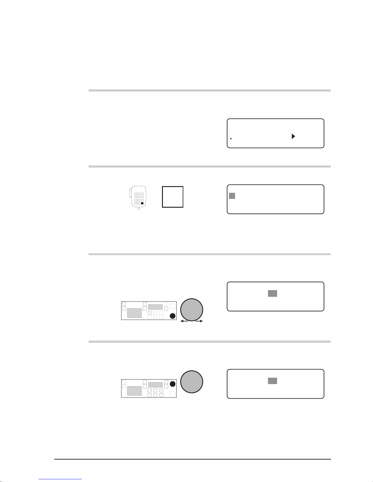
To set up a scan table:
Action Notes
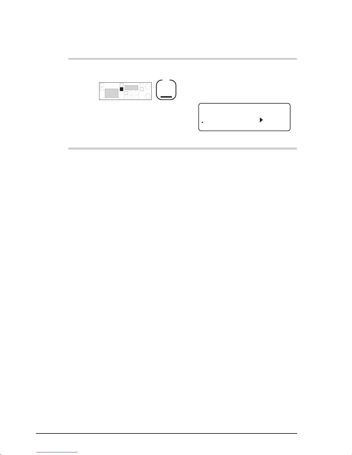
1.
In Channel mode, press
Scan
The display shows:
EXIT
PROGRAM
Press SCAN to Scan
Scan Table: 1
2.
To select one of the three
scan tables, rotate
Select
Select scan table 1, 2 or 3.
3.
Press
F2
Example of the display for scan
table 2:
DELETE
Scan Table: 2
ENTER
F1 to delete table
F2 to program table
Page 56

Channel and scan table setup
3-26 9390 Reference manual
Action Notes
4.
Press
F2
Example of the display:
CLEAR
Scan Table: 2
ENTER
– – – – – – – – – – – – – – – – – – – –
Enter Scan name
5.
To enter a comment to
describe this scan table,
rotate
Select
to select each character
and
Volume
to move along the line to
the next character
position.
Enter up to 20 characters (for
example, Ship to shore).
To clear any existing text, press
F1
6.
Press
F2
Example of the display:
EXIT
Scan Table: 2
ENTER
Continuous scan
Default Scan: Cont
Page 57

Channel and scan table setup
9390 Reference manual 3-27
Action Notes
7.
To switch between the
types of scanning, rotate
Select
Select:
• ‘
Selcall
’ for normal selcall
scanning (option)
• ‘
Cont
’ for scanning without
muting channel traffic
• ‘
Pause
’ for voice call
scanning to pause five
seconds on voice detection
• ‘
Hold
’ for voice call
scanning to hold on voice
detection
• ‘
ALE
’ for ALE call
scanning (option).
8.
Press
F2
Example of the display:
DELETE
Scan Table: 2
PROGRAM
USB
804 8,728.0
Ship to shore
9.
To select the channel to
add to the scan table,
rotate
Select
You can add up to ten channels
to the scan table.
To delete a channel already
added to the scan table
(showing ‘
Prog
’ at the top
right of the display), press
F1
Page 58

Channel and scan table setup
3-28 9390 Reference manual
Action Notes
10.
To add the displayed
channel to the scan table,
press
F2
‘
Prog x1
’ indicates that this
channel is now entered once in
the scan table:
DELETE
Scan Table: 2 Prog x1
PROGRAM
USB
9991 8,731.0
Ship to shore
11.
Do you want to add
another channel to the
scan table?
Yes
Return to
Step 9.
No
Step 12.
12.
To save your changes,
press
Scan
Example of the display:
USB
HI
RF–ON
Rx.
9991
Trawler Network
Pwr
8,204
8,731
Return to Step 2 if you want to
set up another scan table.
Page 59

Channel and scan table setup
9390 Reference manual 3-29
Deleting a scan table
This procedure deletes any of the three scan tables.
You can only delete scan tables if scan table editing is
switched on (see Chapter 8, Scan table editing on/off).
To delete a scan table:
Action Notes
1.
In Channel mode, press
Scan
The display shows:
EXIT
PROGRAM
Press SCAN to Scan
Scan Table: 1
2.
To select one of the three
scan tables for deletion,
rotate
Select
Select scan table 1, 2 or 3.
3.
Press
F2
Example of the display for scan
table 2:
DELETE
Scan Table: 2
ENTER
F1 to delete table
F2 to program table
Page 60

Channel and scan table setup
3-30 9390 Reference manual
Action Notes
4.
Press
F1
Example of the display:
DELETE
Scan Table: 2
EXIT
Ship to shore
F1 to delete table
5.
To delete the scan table,
press
F1
Example of the display:
USB
HI
RF–ON
Rx.
9991
Trawler Network
Pwr
8,204
8,731
Page 61

Channel and scan table setup
9390 Reference manual 3-31
Creating a telephone directory (option)
This procedure sets up the telephone directory for making
telcalls.
Before you can use the telephone directory, you need to enable
the selcall option (see Chapter 7, Password entry to enable
transceiver options).
The telephone directory operates like a telephone book. It can
hold ten telephone entries (numbered 0–9). Each entry
consists of a telephone number and a comment.
You can only access the telephone directory from channels
that allow selcalling by being attached to a selcall group. To
check the selcall group setting for a channel, refer to the 9390
User guide, Chapter 4, Using View Channel Options mode.
To add or clear entries from the telephone directory:
Action Notes
1.
In Channel mode, select a
channel that is set up for
selcalling.
Example of the display for
channel 9951:
9951
RF–ON
Rx.
USB
HI
Fleet channel
Pwr
5820
2.
Press
Call
Example of the display:
USB
HI
CALL
Rx.
9951
5820
TYPE
Selcall: 894477
Page 62

Channel and scan table setup
3-32 9390 Reference manual
Action Notes
3.
Press
Enter
R'call
Example of the display:
USB
HI
CALL
Rx.
9951
5820
ENDCALL
Tel:
– – – – – – –
029712233
4.
Press
Enter
R'call
Example of the display:
CALL
Rx.
PROG
Tel:
– – – – – – – – – – – – – – – –
– – – – – – – – – – – – – – – – – – – –
Ch: 9951 Tel-Dir:0
5.
To select one of the ten
entries, rotate
Select
Select entry 0–9.
6.
Press
F2
Example of the display for
entry 3:
EXIT
Rx.
ENTER
– – – – – – – – – – – – – – – – – – – –
Edit Tel Tel-Dir:3
Tel:
– – – – – – – – – – – – – – – –
7.
Enter the telephone
number
numeral
buttons
To cancel an existing number
and leave this entry unused,
enter 0.
Page 63

Channel and scan table setup
9390 Reference manual 3-33
Action Notes
8.
Press
F2
Example of the display for
number 083050311:
CLEAR
Rx.
ENTER
Edit Text Tel-Dir:3
Tel:
– – – – – – – –
083050311
– – – – – – – – – – – – – – – – – – – –
9.
To enter a comment, rotate
Select
to select each character
and
Volume
to move along the line to
the next character
position.
Enter up to 20 characters to
describe the number (for
example, person’s name and
location).
To clear any existing text, press
F1
10.
To save your changes,
press
F2
Example of the display:
CALL
Rx.
PROG
Tel:
083050311
Codan Adelaide
Ch: 9951 Tel-Dir:3
11.
Do you want to add
another telephone
number?
Yes
Return to
Step 5.
No
Step 12.
Page 64

Channel and scan table setup
3-34 9390 Reference manual
Action Notes
12.
To return to Channel
mode, press
PTT
Example of the display:
9951
RF–ON
Rx.
USB
HI
Fleet channel
Pwr
5820
Page 65

9390 Reference manual 4-1
4 Using Setup mode
Setup mode allows you to view and change settings that
control transceiver operation.
This chapter:
• explains how to use Setup mode (4-2)
• lists the procedures available in Setup mode (4-3)
• gives some tips on using Setup mode for advanced users
(4-7).
You should read this chapter before running any of the Setup
mode procedures. Chapters 5–8 cover Setup mode
procedures in detail.
Page 66

Using Setup mode procedures
4-2 9390 Reference manual
Using Setup mode
You enter Setup mode by pressing the
Mode
button on the
control panel four times starting with the Channel mode
setting.
The easiest way to use Setup mode is to find which procedure
you want from the following list and turn to the description of
the procedure for further details and step by step guidance.
Procedures are listed in Chapters 5–8.
You start each transceiver procedure by entering a setup
code.
Procedures labelled optional are only available if you contact
Codan for a password to enable them in your transceiver (see
Chapter 7, Password entry to enable transceiver options).
If you make a mistake in setting a value and want to avoid
saving your changes, press the F1 button on the control panel
or
PTT
button on the microphone to return to an earlier step
in the procedure. Repeated pressing of either button
progresses you back to Channel mode.
If you do not touch any button or knob for 60 seconds while
in Setup mode, the transceiver automatically reverts to
Channel mode. If this happens while you are in the middle of
a procedure, start the procedure again.
The descriptions for the procedures show examples of
channel and frequency numbers. You must enter your own
values.
Page 67

Using Setup mode procedures
9390 Reference manual 4-3
List of Setup mode procedures
Procedure Page Setup
code
Description
ALE option settings 5-2 2431 Controls how the ALE controller works
(option).
ALE option reset 5-9 2432 Resets the ALE option settings 0–16 to their
factory values (option).
ALE sounding
interval
5-11 2433 Changes the ALE sounding time interval
(option).
Beep loudness 5-13 33 Controls the volume of ‘beep’ tones made by
the transceiver.
Call preamble
length
5-15 242 Sets the length of the preamble transmitted at
the start of a selcall or ALE call (option).
Call privacy on/off 5-17 2443 Limits the stations that can receive your
transmissions of GPS and page information
(option).
Clock calibration 5-19 412 Calibrates the transceiver clock against an
external standard.
Clock setting 5-21 411 Sets the time and date of the transceiver
clock.
Clone a transceiver 5-26 Copies the settings from one transceiver to
another by a process called cloning.
Display brightness 6-2 311 Controls the brightness of the display.
Display contrast 6-4 312 Controls the contrast of the display.
Page 68

Using Setup mode procedures
4-4 9390 Reference manual
Procedure Page Setup
code
Description
Display frequency 6-6 313 Controls the displayed channel frequency.
Free-Tune Receiver
mode availability
on/off
6-9 3442 Controls the use of Free-Tune Receiver mode.
GPS display on/off 6-11 3421 Switches on or off the display of your
transceiver’s GPS latitude and longitude
(option).
GPS timeout on/off 6-13 3422 Switches GPS timeout warning on or off
(option).
Password entry to
enable transceiver
options
7-2 42 Enables transceiver options that are built into
the transceiver and deletes forgotten PINs.
Power up message
on/off
7-8 34411 Allows you to set up a message which is
displayed for several seconds when the
transceiver is powered up.
Power up mute
setting
7-11 34412 Controls the initial mute setting used when the
transceiver is powered up.
Power up selcall
self ID display
on/off
7-14 34413 Controls whether the self ID is displayed
when the transceiver is powered up (option).
PTT release beep
on/off
7-16 3432 Switches PTT release ‘beeping’ on or off.
PTT transmit
cut-out
7-18 3431 Prevents the transceiver from being left on in
the transmit state by mistake.
Recall channels by
frequency on/off
7-20 32 Controls whether you can recall channels by
frequency as well as channel number.
Page 69

Using Setup mode procedures
9390 Reference manual 4-5
Procedure Page Setup
code
Description
RF gain on/off 7-22 3443 Controls the RF gain to change the receive
sensitivity.
RS-232 connected
equipment
7-24 3411 Controls what equipment is connected to the
transceiver rear panel.
RS-232 connection
baud rate
7-27 3412 Sets the speed of information transfer for
equipment connected to the transceiver rear
panel.
Scan table
automatic scanning
start
8-2 11 Sets the time delay for starting automatic
scanning.
Scan table editing
on/off
8-4 12 Switches scan table editing on or off.
Selcall ID setup 8-6 211 Sets up IDs for any of the transceiver’s five
selcall groups S1–S5 (option).
Selcall ID size
compatibility
8-13 213 Controls how you communicate with stations
that are incapable of using IDs longer than
four digits (option).
Selcall lockout
on/off
8-16 2441 Switches selcall lockout on or off (option).
Selcall mute
availability on/off
8-19 212 Controls whether you can select selcall mute
from the control panel (option).
Telcall availability
on/off
8-21 22 Controls whether your transceiver can send
telcalls (option).
Page 70
Using Setup mode procedures
4-6 9390 Reference manual
Procedure Page Setup
code
Description
Tone call setup 8-23 23 Sets up the high and low frequency pairs for
any of the four tone call groups T1–T4.
99-Beacon call
response on/off
8-26 241 Controls whether the transceiver can respond
to received 99-beacon calls (option).
Page 71

Using Setup mode procedures
9390 Reference manual 4-7
Advanced users
This section explains how Setup mode procedures are
arranged in the transceiver. You do not need to understand
this to use Setup mode, but some readers may find this
knowledge useful.
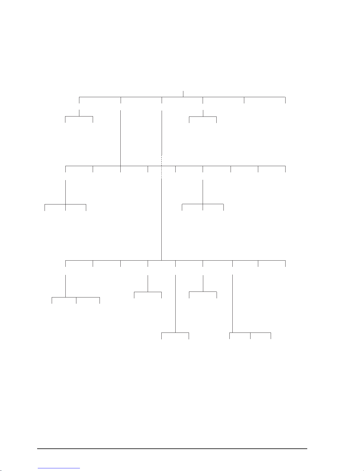
The Setup mode tree in Figure 4.1 shows how Setup mode
procedures are accessed. Each menu of options displayed by
the transceiver is represented by a branch in this tree.
Page 72
Using Setup mode procedures
4-8 9390 Reference manual
Selcall* ALE*
Display GPS* PTTRS232 Power Up
Emgcy
(Not Used)
Privacy*
Call privacy
on/off (2443)
CallScan Config Time
Auto
Scan table
automatic
scanning
start (11)
Enable
Scan table
editing
on/off (12)
Calib
Clock
calibration
(412)
Password
Password
entry to
enable
transceiver
options (42)
Clone
Clone a
transceiver
Set
Clock
setting
(411)
Setup mode menus
Telcall*
Telcall
availability
on/off (22)
Tone
Tone call
setup
(23)
Beacon*
99-Beacon
call
response
on/off (241)
Preamble*
Call preamble
length (242)
Lockout*
Selcall
lockout
on/off (2441)
Sound*
ALE
sounding
interval
(2433)
Default*
ALE option
reset (2432)
Options*
ALE option
settings
(2431)
Timeout*
GPS timeout
on/off (3422)
Display*
GPS
display
on/off
(3421)
PTT Beep
PTT release
beep on/off
(3432)
Timer
PTT
transmit
cutout
(3431)
Config
RS-232
connection
baud rate
(3412)
Mode
RS-232
connected
equipment
(3411)
Show ID*
Power up Selcall
self ID display
on/off (34413)
Mute
Power up
mute
setting
(34412)
Message
Power up
message
on/off
(34411)
RF Gain
RF gain
on/off
(3443)
Receiver
Free-Tune
Receiver
mode
availability
on/off (3442)
Contrast
Display
contrast
(312)
Bright
Display
brightness
(311)
Beeps
Beep
loudness
(33)
Recall
Recall
channels by
frequency
on/off (32)
ID*
Selcall
ID
setup
(211)
Mute*
Selcall
mute
availability
on/off
(212)
ID size*
Selcall ID
size
compatibility
(213)
Only available if this option
has been enabled in your
transceiver
*
Format
Display
frequency
(313)
Figure 4.1
The Setup mode tree
Page 73

Using Setup mode procedures
9390 Reference manual 4-9
If you are comfortable using menus and selecting menu
options, you can refer to the Setup mode tree instead of
entering setup codes to access each procedure. This allows
you to use Setup mode by directly following the guidance
shown on the transceiver display.
Each branch in the menu tree shows:
• the name of the menu item shown on the display
• the name in small print of the equivalent procedure in
this manual, if any, for this menu item
• the setup code in parentheses.
To navigate around the Setup mode tree, use front panel
button:
•
F2
to select a highlighted menu option and advance
down the tree
•
F1
to go back up the tree to the previous menu.
For example, you could branch down to the ‘
Power Up
’
menu and view each of the ‘
Power Up
’ menu options,
‘
Message
’, ‘
Mute
’ and ‘
Show ID
’, in turn making any
changes to settings as necessary.
Page 74

Using Setup mode procedures
4-10 9390 Reference manual
Page 75

9390 Reference manual 5-1
5 Setup procedures (part 1)
This chapter describes the following Setup mode procedures:
• ALE option settings (option, 5-2)
• ALE option reset (option, 5-9)
• ALE sounding interval (option, 5-11)
• Beep loudness (5-13)
• Call preamble length (option, 5-15)
• Call privacy on/off (option, 5-17)
• Clock calibration (5-19)
• Clock setting (5-21)
• Clone a transceiver (5-26).
Page 76

Setup procedures (part 1)
5-2 9390 Reference manual
ALE option settings (option)
Setup code 2431
This procedure controls how the ALE (Automatic Link
Establishment) controller works.
Before you can use this procedure, you need to enable both the
selcall and ALE options (see Chapter 7, Password entry to
enable transceiver options).
There are 17 ALE system settings numbered 0–16. These
settings control ALE call performance and do not usually
require changing. You can change nine. The remaining eight
are not displayed since their values are fixed.
Setting No. Description
0 Sounding On/Off
2 Channel Quality Decay Time
3 Sounding Signal Length
5 BER Threshold
6 Golay Threshold
7 Error Threshold
11 ALE Silent Mode
13 Call Retry Limit
14 Channel Quality Averaging
For further information, this manual should be read in
conjunction with the 9300 ALE controller user guide (Codan
part number 15-04046).
Page 77

Setup procedures (part 1)
9390 Reference manual 5-3
Sounding On/Off (ALE option 0)
This ALE option switches sounding on or off.
When sounding is switched off, your transceiver no longer
sends or receives ALE sounding signals. For correct ALE
operation, you should leave sounding on all the time.
If ALE Silent Mode (ALE option 11) is switched on, the
Sounding On/Off option setting is ignored and your station
does not send or receive ALE sounding signals. To set the
sounding interval, see ALE sounding interval on page 5-11.
Channel Quality Decay Time (ALE option 2)
This ALE option sets the artificial decay time for the record
of channel quality that is stored in the channel quality table in
ALE controller memory.
You can switch decay off or set a decay time in the range
1–8 hours.
For example, switching the sounding off and setting a decay
time of four hours would result in the record of a perfect
channel (100% channel quality) decaying to an unusable
channel (0% channel quality) over a period of four hours.
Sounding Signal Length (ALE option 3)
This ALE option sets the length in seconds of the sounding
transmission for each channel in the scan group.
When an ALE station sends sounding signals, a separate
signal is transmitted for each channel in the scan group. The
ALE station sends these signals sequentially. The total length
of the sounding transmission is the product of the sounding
signal length and the number of channels.
For example, if the sounding signal length is set to 10 seconds
and the scan group contains seven channels, the ALE station
takes 70 seconds to complete sounding transmission.
Page 78

Setup procedures (part 1)
5-4 9390 Reference manual
The default sounding signal length is the minimum setting
(under five seconds). The maximum setting is 100 seconds.
Bit Error Rate (BER) Threshold (ALE option 5)
This ALE option sets the value of the BER Threshold used in
BER testing.
You can set a value in the range 0–48.
BER testing is a method of error detection for ALE word
transmission. ALE stations send and receive ALE link
controlling information in blocks of data called ALE words.
An ALE word consists of a 3-bit preamble and a 21-bit data
field.
The result of BER error testing is used in helping to decide
whether the ALE link can be established using the current
channel.
The higher the BER value of a transmitted ALE word, the
greater the error. A BER value of 0 indicates perfect
reception of an ALE word. The maximum BER value of 48
indicates that all bits of the ALE word were bad.
If a received ALE word contains more errors than the BER
Threshold, the ALE controller rejects the word. The lower
you set the BER Threshold, the tougher the test for rejecting
transmission errors.
Golay Threshold (ALE option 6)
This ALE option sets the value of the Golay Threshold used
in Golay testing.
You can set a value in the range 0–4.
Golay testing is an additional method of error detection for
ALE word transmission. The result of Golay error testing is
used in helping to decide whether the ALE link can be
established using the selected channel.
Page 79

Setup procedures (part 1)
9390 Reference manual 5-5
The higher the Golay value calculated for a received ALE
word, the greater the error.
If a received ALE word contains more errors than the Golay
Threshold, the ALE controller rejects the word. The lower
you set the Golay Threshold, the tougher the test for rejecting
transmission errors.
Error Threshold (ALE option 7)
This ALE option sets the maximum number of sequentially
received bad ALE words which are allowed before the ALE
controller decides that the quality of the current channel is too
poor to establish an ALE link. A bad word is a word that has
exceeded either the BER or Golay Threshold.
You can set a value in the range 0–4.
If the test fails during the process of establishing the ALE
link, the call aborts and the transceiver returns to Scan mode.
ALE Silent Mode (ALE option 11)
This ALE option switches ALE Silent mode on or off.
When ALE Silent mode is switched off, the station runs as a
normal ALE station.
When ALE Silent mode is switched on, the station no longer:
• recognises any incoming ALE calls
• sends or receives sounding signals even if Sounding
On/Off (ALE option 0) is switched on.
You can still send ALE calls in ALE Silent mode.
Page 80

Setup procedures (part 1)
5-6 9390 Reference manual
Call Retry Limit (ALE option 13)
This ALE option controls the number of times the ALE
station tries to establish an ALE link using each channel in
turn from the scan group.
You can set 99 for no limit or a value in the range 0–98.
On each selected channel, two attempts are made to establish
a link before trying the next preferred channel, where two
more attempts are made and so on, until all channels in the
scan table have been tried (unless a link is established).
The sequence is then repeated dependent upon the number set
in the Call Retry Limit.
If a link is not established, the display shows ‘
LINK FAILED
’
accompanied by error ‘beeps’. Retry duration can be up to
one minute per channel.
Channel Quality Averaging (ALE option 14)
This ALE option sets the method used to update an existing
channel quality value stored in ALE controller memory when
the new channel quality reading is worse than the stored
value.
You can:
• replace old values with new readings
• replace old values with different weighted averages of the
old values and new readings.
Averaging reduces the effect that one bad reading might
otherwise have on a perfect channel. If a new reading is better
than an old value, the old value is replaced by the reading.
Page 81
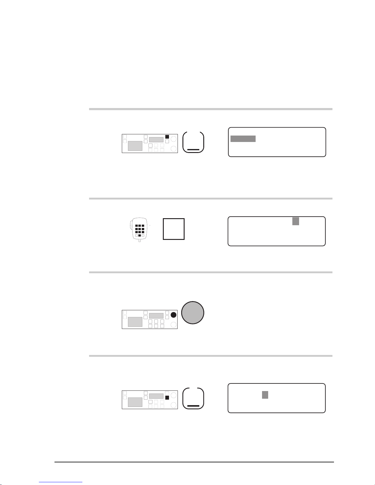
Setup procedures (part 1)
9390 Reference manual 5-7
Changing an ALE option setting
To change an ALE option setting:
Action Notes
1.
Repeatedly press
Mode
until you see the display
for Setup mode.
The display shows:
EXIT
SETUP MENU
1- Scan-
2–Call
ENTER
3–Config
4–More
1/2
2.
Enter 2431
numeral
buttons
Example of the display:
EXIT
ALE Sounding on
ENTER
ENABLED
ALE System Option: 0
3.
To find the ALE option
you want to change, rotate
Select
The name of the option setting
is shown on the third line of
each display.
You can only display and
change nine of the 17 ALE
options (numbered 0–16).
4.
To select this ALE option,
press
F2
For example, option 13 (Call
Retry Limit) looks like this:
EXIT
Call retry limit
ENTER
0
ALE System Option: 13
Page 82

Setup procedures (part 1)
5-8 9390 Reference manual
Action Notes
5.
To change the setting,
rotate
Select
6.
To save your change,
press
F2
Example of the display:
EXIT
Call retry limit
ENTER
1
ALE System Option: 13
7.
Do you want to change
another ALE option?
Yes
Return to
Step 3.
No
Step 8.
8.
To return to Channel
mode, press four times
F1
Example of the display:
USB
HI
RF–ON
Rx.
422
Radphone
Pwr
4,128
4,420
Page 83
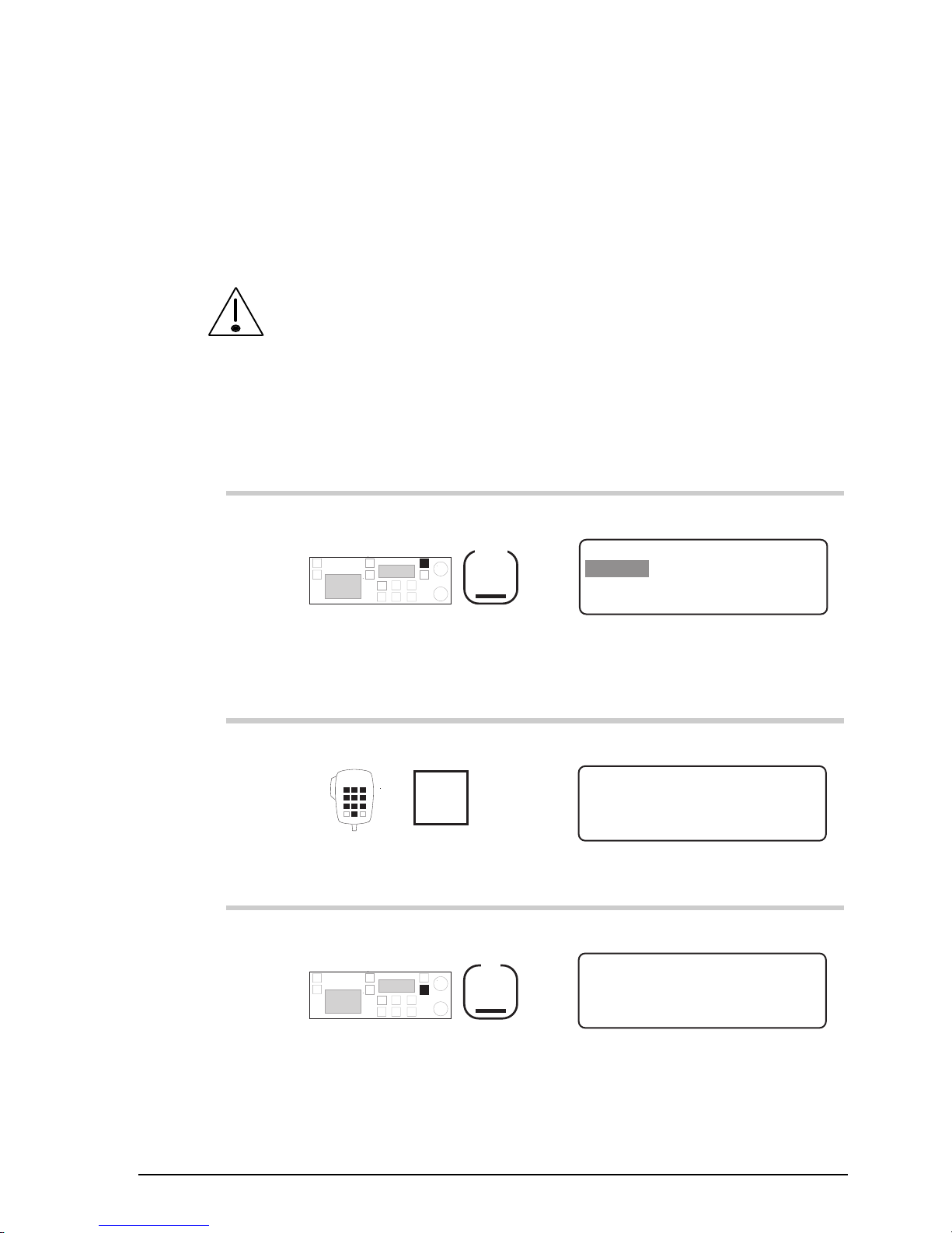
Setup procedures (part 1)
9390 Reference manual 5-9
ALE option reset (option)
Setup code 2432
This procedure resets 9 of the 17 ALE (Automatic Link
Establishment) option settings 0–16 to their factory values.
Before you can use this procedure, you need to enable both the
selcall and ALE options (see Chapter 7, Password entry to
enable transceiver options).
To reset the ALE option settings:
Action Notes
1.
Repeatedly press
Mode
until you see the display
for Setup mode.
The display shows:
EXIT
SETUP MENU
1- Scan-
2–Call
ENTER
3–Config
4–More
1/2
2.
Enter 2432
numeral
buttons
The display shows:
EXIT ENTER
Press ENTER to reset
ALE system options
3.
Press
F2
The display shows:
EXIT ENTER
Press ENTER again to
reset ALE options
Page 84

Setup procedures (part 1)
5-10 9390 Reference manual
Action Notes
4.
To confirm resetting, press
F2
The transceiver ‘beeps’ after
resetting all ALE options.
The display shows:
EXIT
ALE MENU
1–Options
ENTER
3–Sound
2–Default
5.
To return to Channel
mode, press three times
F1
Example of the display:
USB
HI
RF–ON
Rx.
422
Radphone
Pwr
4,128
4,420
Page 85

Setup procedures (part 1)
9390 Reference manual 5-11
ALE sounding interval (option)
Setup code 2433
This procedure changes the ALE (Automatic Link
Establishment) sounding time interval.
Before you can use this procedure, you need to enable both the
selcall and ALE options (see Chapter 7, Password entry to
enable transceiver options).
ALE stations repeatedly send sounding signals to determine
how good each channel is for transmission. The ALE
sounding interval is the time between signal transmissions.
You can select:
• ‘
30 Mins
’
• ‘
45 Mins
’
• ‘
1 Hour
’
• ‘
2 Hours
’
• ‘
4 Hours
’
• ‘
8 Hours
’
• ‘
16 Hours
’.
To change the ALE sounding time interval:
Action Notes
1.
Repeatedly press
Mode
until you see the display
for Setup mode.
The display shows:
EXIT
SETUP MENU
1- Scan-
2–Call
ENTER
3–Config
4–More
1/2
Page 86
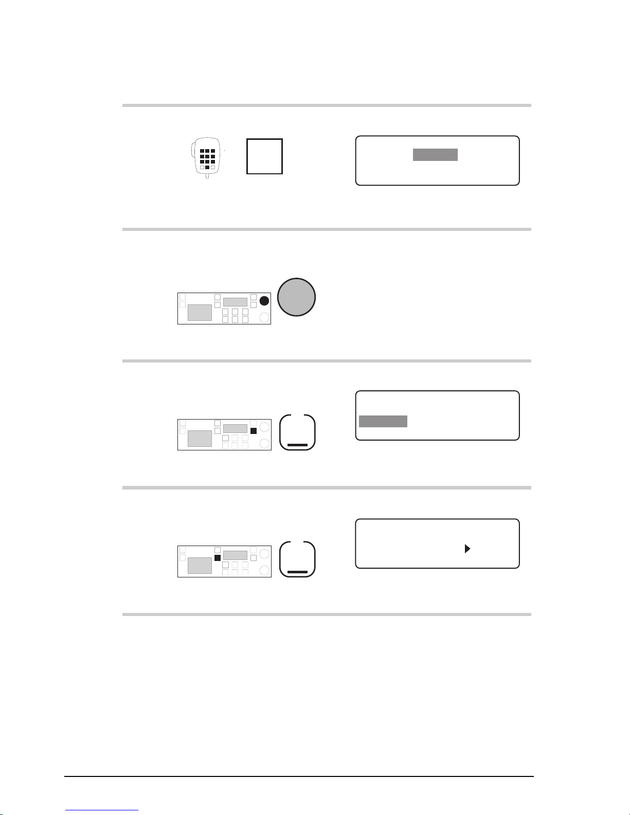
Setup procedures (part 1)
5-12 9390 Reference manual
Action Notes
2.
Enter 2433
numeral
buttons
Example of the display:
EXIT
Sounding Interval
ENTER
2 Hours
Set ALE Sounding
3.
To change the ALE
sounding interval, rotate
Select
Select a time in the range 30
minutes to 16 hours.
4.
To save your change,
press
F2
The display shows:
EXIT
ALE MENU
1–Options
ENTER
3–Sound
2–Default
5.
To return to Channel
mode, press three times
F1
Example of the display:
USB
HI
RF–ON
Rx.
422
Radphone
Pwr
4,128
4,420
Page 87

Setup procedures (part 1)
9390 Reference manual 5-13
Beep loudness
Setup code 33
This procedure controls the volume of ‘beeps’ made by the
transceiver.
You can select:
• ‘
NORMAL
’ (error ‘beeps’ loud, acceptance ‘beeps’ soft)
• ‘
SOFT
’ (all ‘beeps’ soft)
• ‘
LOUD
’ (all ‘beeps’ loud).
To change the ‘beep’ loudness:
Action Notes
1.
Repeatedly press
Mode
until you see the display
for Setup mode.
The display shows:
EXIT
SETUP MENU
1- Scan-
2–Call
ENTER
3–Config
4–More
1/2
2.
Enter 33
numeral
buttons
The display looks like one of
the following:
EXIT
Soft and loud beeps
ENTER
NORMAL
Adjust Beep Volume
EXIT
Always soft beeps
ENTER
SOFT
Adjust Beep Volume
EXIT
Always loud beeps
ENTER
LOUD
Adjust Beep Volume
Page 88

Setup procedures (part 1)
5-14 9390 Reference manual
Action Notes
3.
To switch between
‘
NORMAL
’, ‘
SOFT
’ and
‘
LOUD
’, rotate
Select
Select:
• ‘
NORMAL
’ if you want
loud error ‘beeps’ and soft
acceptance ‘beeps’
• ‘
SOFT
’ if you always want
soft ‘beeps’
• ‘
LOUD
’ if you always want
loud ‘beeps’.
4.
To save your change,
press
F2
The display shows:
EXIT
CONFIG MENU
1–Display
2–Recall
ENTER
3–Beeps
4–More
1/3
5.
To return to Channel
mode, press twice
F1
Example of the display:
USB
HI
RF–ON
Rx.
422
Radphone
Pwr
4,128
4,420
Page 89
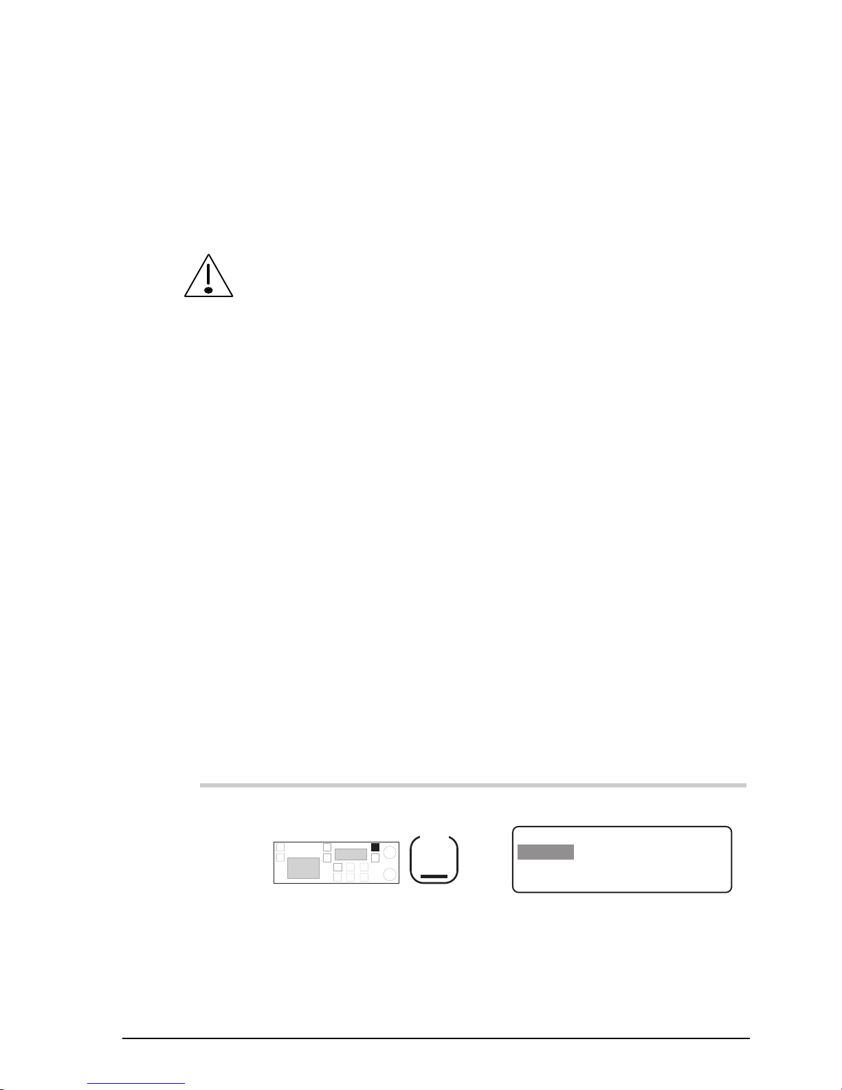
Setup procedures (part 1)
9390 Reference manual 5-15
Call preamble length (option)
Setup code 242
This procedure sets the length of the preamble transmitted at
the start of a selcall or ALE call.
Before you can use this procedure, you need to enable the
selcall option (see Chapter 7, Password entry to enable
transceiver options).
To send an ALE call, your station needs to be set up with an
ALE controller.
The preamble is part of the coded selcall and ALE message
structure which is transmitted when you send a call. The
preamble allows the receiving station sufficient time to scan
to the selected channel and recognise the incoming call. ALE
calls need a longer preamble than selcalls.
You can set the preamble for:
• ‘
Selcall
’
• ‘
ALE
’.
The ‘
Selcall
’ preamble lasts six seconds. The ‘
ALE
’
preamble lasts 12 seconds.
To change the preamble length:
Action Notes
1.
Repeatedly press
Mode
until you see the display
for Setup mode.
The display shows:
EXIT
SETUP MENU
1- Scan-
2–Call
ENTER
3–Config
4–More
1/2
Page 90

Setup procedures (part 1)
5-16 9390 Reference manual
Action Notes
2.
Enter 242
numeral
buttons
The display shows:
EXIT ENTER
SELCALL
Setup Call Preamble
Selcall preamble
or
EXIT ENTER
ALE
Setup Call Preamble
ALE preamble
3.
To switch between
‘
SELCALL
’ and ‘
ALE
’,
rotate
Select
Select:
• ‘
SELCALL
’ if you are not
using an ALE controller
• ‘
ALE
’ if you are using an
ALE controller to send
calls.
4.
To save your change,
press
F2
The display shows:
EXIT
CALL MENU
1–Beacon
2–Preamble
ENTER
3–ALE
4–More
2/3
5.
To return to Channel
mode, press twice
F1
Example of the display:
USB
HI
RF–ON
Rx.
422
Radphone
Pwr
4,128
4,420
Page 91
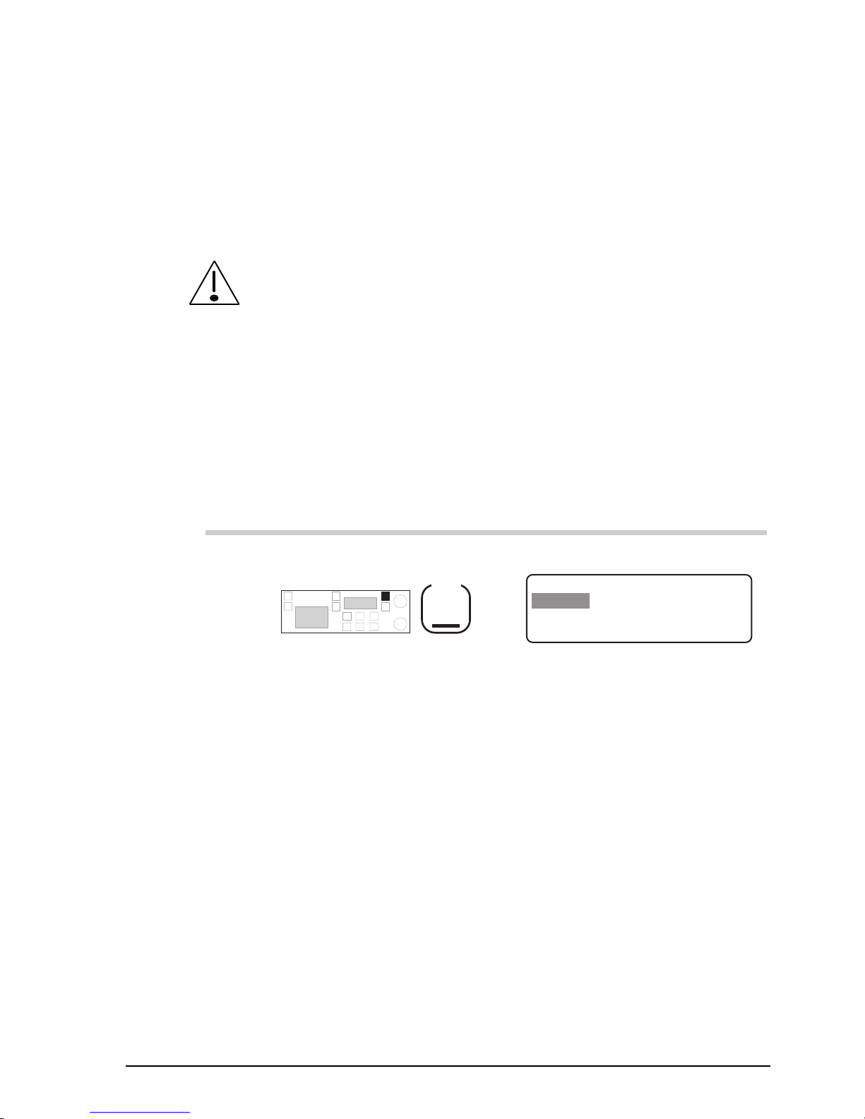
Setup procedures (part 1)
9390 Reference manual 5-17
Call privacy on/off (option)
Setup code 2443
This procedure limits the stations that can receive your
transmissions of GPS and page information.
Before you can use this procedure, you need to enable the
selcall option (see Chapter 7, Password entry to enable
transceiver options).
You switch on call privacy by setting a privacy key (a number
up to six digits). This restricts the stations that can receive
your information to those using an identical privacy key.
To switch call privacy on or off:
Action Notes
1.
Repeatedly press
Mode
until you see the display
for Setup mode.
The display shows:
EXIT
SETUP MENU
1- Scan-
2–Call
ENTER
3–Config
4–More
1/2
Page 92

Setup procedures (part 1)
5-18 9390 Reference manual
Action Notes
2.
Enter 2443
numeral
buttons
If privacy is unset, the privacy
key is shown as 0 like this:
EXIT
Enter Privacy Key
ENTER
Key: – – – – – 0
If privacy is set, the privacy
key is hidden like this:
EXIT
Enter Privacy Key
ENTER
Key:
******
3.
Enter the privacy key
numeral
button
Enter up to six digits.
To switch call privacy off,
enter 0 for the privacy key.
4.
To save your change,
press
F2
The display shows:
EXIT
CALL MENU
1–Lockout
2–Emgcy
ENTER
3/3
4–More
3–Privacy
5.
To return to Channel
mode, press twice
F1
Example of the display:
USB
HI
RF–ON
Rx.
422
Radphone
Pwr
4,128
4,420
Page 93

Setup procedures (part 1)
9390 Reference manual 5-19
Clock calibration
Setup code 412
This procedure calibrates the transceiver clock against an
external standard.
The clock is used for timing incoming selective calls recorded
in call memory.
You can adjust the running of the clock by changing the
number of seconds that the clock gains or loses each month.
The calibration range is -150 to +310 seconds/month in steps
of 10 (approximate values).
The first time you calibrate the clock, set the value to zero
seconds/month. Over a period of a few months, see if the
clock gains or loses time and recalibrate as necessary.
To calibrate the clock:
Action Notes
1.
Repeatedly press
Mode
until you see the display
for Setup mode.
The display shows:
EXIT
SETUP MENU
1- Scan-
2–Call
ENTER
3–Config
4–More
1/2
2.
Enter 412
numeral
buttons
The display shows:
EXIT
TIME CALIBRATION
ENTER
Only use to adjust
fast or slow clock
Page 94
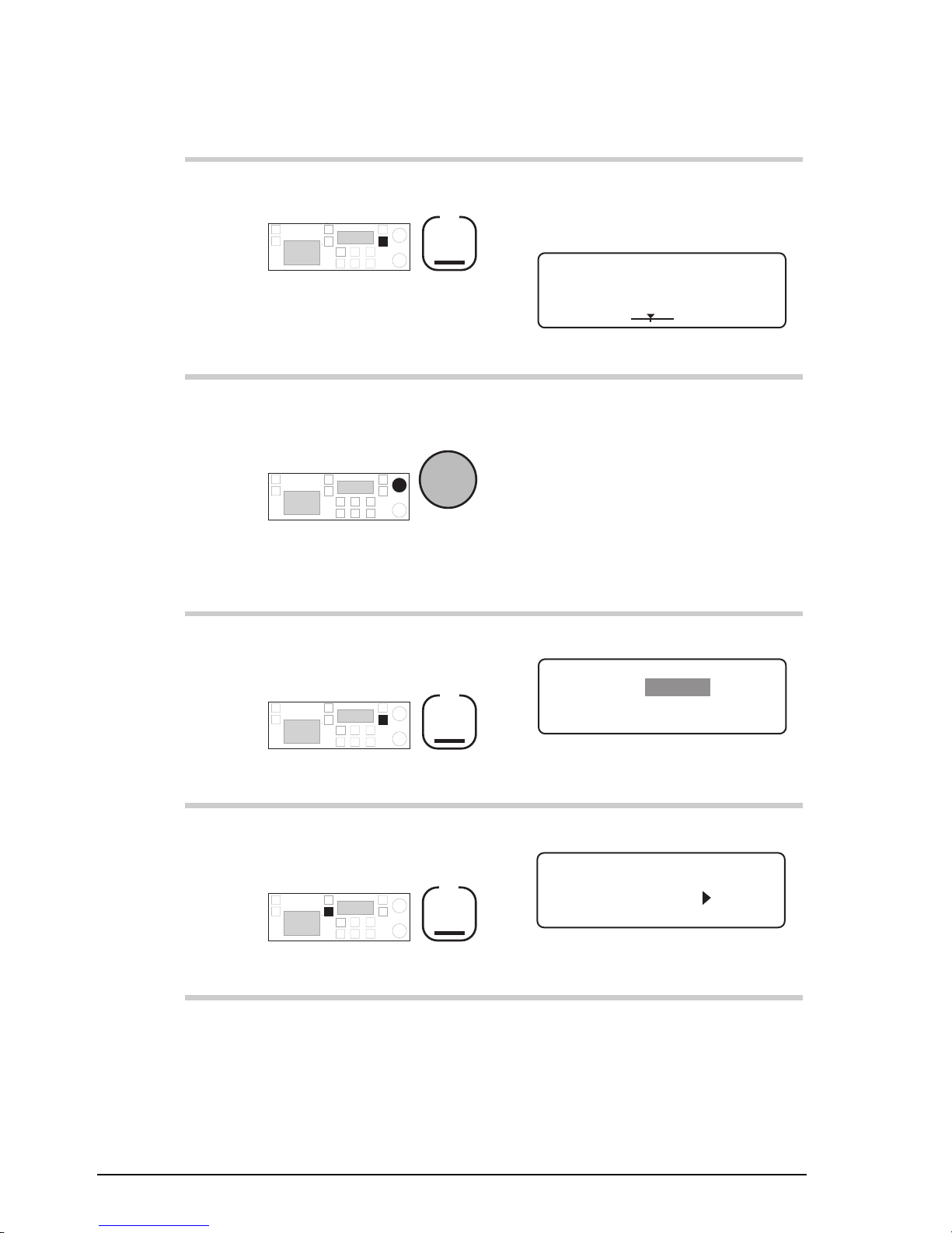
Setup procedures (part 1)
5-20 9390 Reference manual
Action Notes
3.
Press
F2
The display shows the day and
time that the calibration was
last set:
EXIT
TIME CALIBRATION
ENTER
Last 04/06/96 18:04
+010 sec/month
+--
4.
To change the calibration
setting, rotate
Select
The calibration range is -150 to
+310 seconds/month in steps of
10.
As you change the value, the
slider moves at the bottom of
the screen—as displayed
above.
5.
To save your change,
press
F2
The display shows:
EXIT
TIME SETUP MENU
ENTER
1– Set
2–Calib
6.
To return to Channel
mode, press twice
F1
Example of the display:
USB
HI
RF–ON
Rx.
422
Radphone
Pwr
4,128
4,420
Page 95

Setup procedures (part 1)
9390 Reference manual 5-21
Clock setting
Setup code 411
This procedure sets the time and date of the transceiver clock.
The time is always shown in 24 hour format. The clock is
used for timing incoming selective calls recorded in call
memory.
To change the clock setting, you must complete the
procedure. If you exit the procedure before the end, all
changes are lost.
The clock stops during the procedure. When you complete the
procedure, it restarts using the new settings.
To set the clock:
Action Notes
1.
Repeatedly press
Mode
until you see the display
for Setup mode.
The display shows:
EXIT
SETUP MENU
1- Scan-
2–Call
ENTER
3–Config
4–More
1/2
2.
Enter 411
numeral
buttons
The clock stops running.
Example of the display:
EXIT
TIME SETUP
16:01 D/M/Y 03/05/96
ENTER
Enter hours
Page 96

Setup procedures (part 1)
5-22 9390 Reference manual
Action Notes
3.
Enter the hour if you want
to change the hour
numeral
buttons
Use 24-hour format. For
example, enter 18 for 6 pm.
4.
Press
F2
Example of the display:
EXIT
TIME SETUP
16:01 D/M/Y 03/05/96
ENTER
Enter minutes
5.
Enter the minutes if you
want to change the
minutes
numeral
buttons
6.
Press
F2
Example of the display:
EXIT
TIME SETUP
16:01 D/M/Y 03/05/96
ENTER
Select date format
Page 97

Setup procedures (part 1)
9390 Reference manual 5-23
Action Notes
7.
To switch between
‘
D/M/Y
’ and ‘
M/D/Y
’ date
formats, rotate
Select
Select:
• ‘
D/M/Y
’ for day/month/year
• ‘
M/D/Y
’ for
month/day/year.
8.
Press
F2
Example of the display:
EXIT
TIME SETUP
16:01 D/M/Y 03/05/96
ENTER
Enter days
9.
Enter the day for the
‘
D/M/Y
’ format if you
want to change the day (or
month for the ‘
M/D/Y
’
format)
numeral
buttons
10.
Press
F2
Example of the display:
EXIT
TIME SETUP
16:01 D/M/Y 03/05/96
ENTER
Enter months
Page 98
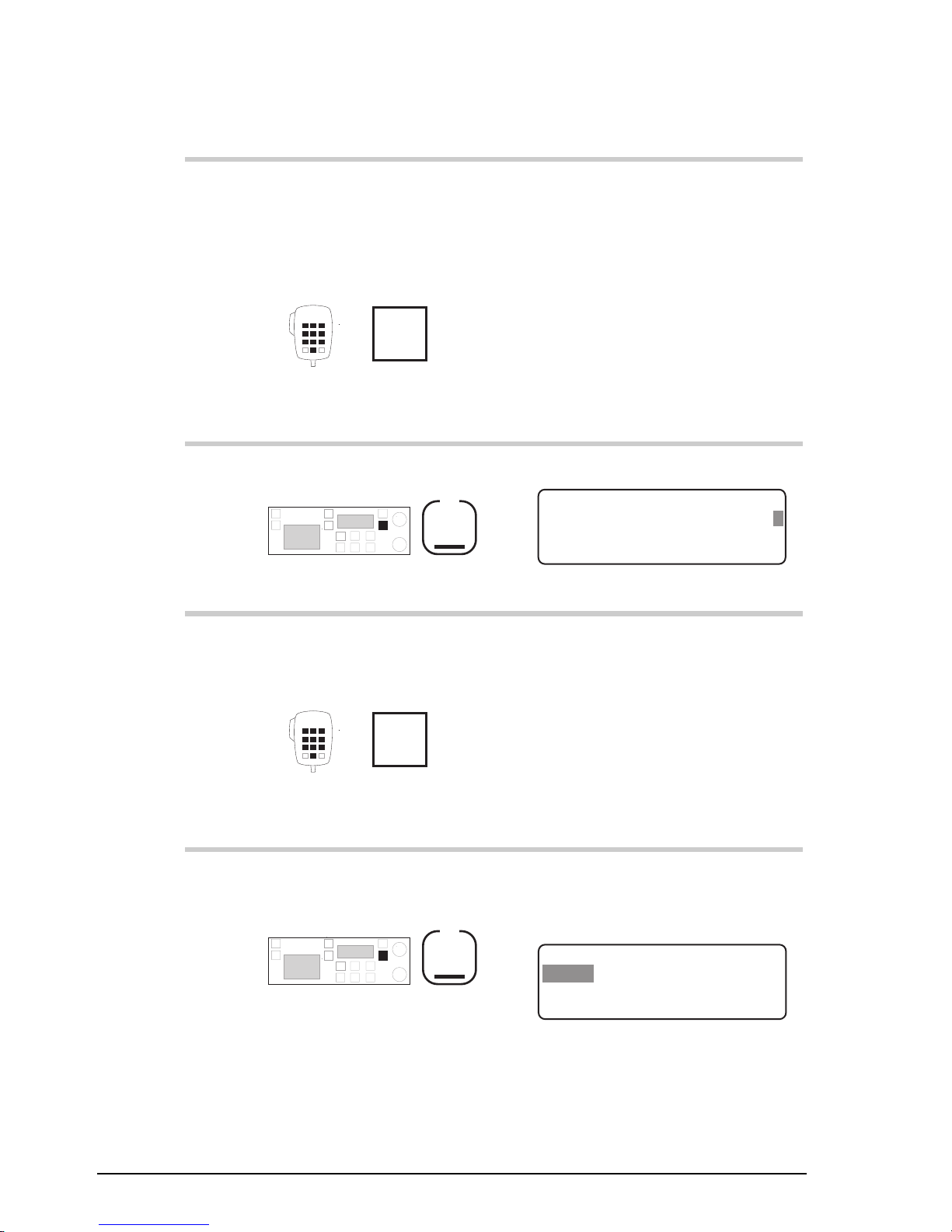
Setup procedures (part 1)
5-24 9390 Reference manual
Action Notes
11.
Enter the month for the
‘
D/M/Y
’ format if you
want to change the month
(or day for the ‘
M/D/Y
’
format)
numeral
buttons
12.
Press
F2
Example of the display:
EXIT
TIME SETUP
16:01 D/M/Y 03/05/96
SAVE
Enter years
13.
Enter the last two digits of
the year if you want to
change the year
numeral
buttons
For example, enter 96 for 1996.
14.
To save all changes to the
time and date, press
F2
The clock restarts at the time
the F2 button is pressed. The
display shows:
EXIT
TIME SETUP MENU
2–Calib
ENTER
1– Set
Page 99
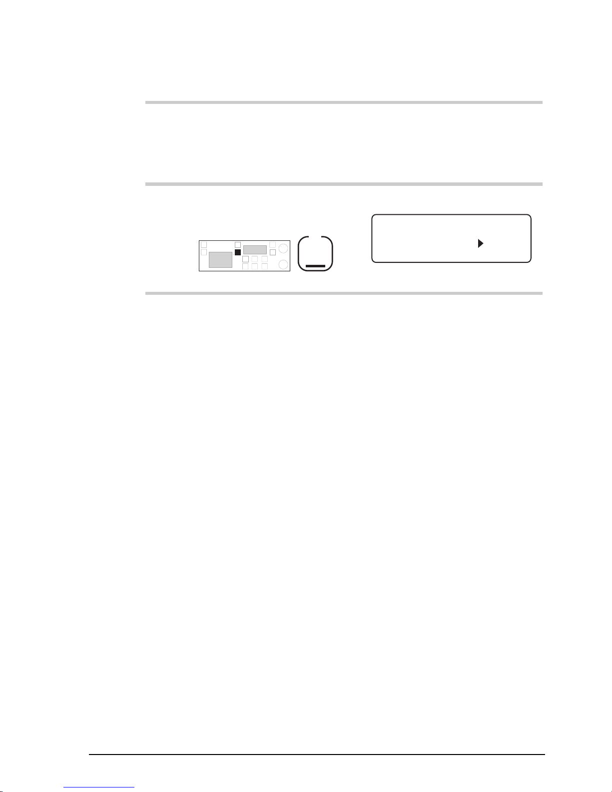
Setup procedures (part 1)
9390 Reference manual 5-25
Action Notes
15.
If you are setting the clock
for the first time, calibrate
the clock.
Set calibration to zero
seconds/month. See Clock
calibration on page 5-19.
16.
To return to Channel
mode, press twice
F1
Example of the display:
USB
HI
RF–ON
Rx.
422
Radphone
Pwr
4,128
4,420
Page 100

Setup procedures (part 1)
5-26 9390 Reference manual
Clone a transceiver
This procedure copies the settings from one 9390 transceiver
to another by a process called cloning. Cloning allows you to
set up several 9390 transceivers that all work in exactly the
same way.
You clone transceivers by connecting the microphone socket
of the transceiver which is already set up to the microphone
socket of a transceiver which is to be cloned.
You can obtain the cable required for this procedure from an
authorised Codan dealer (Codan part no. 08-05138-001).
Except for the PIN and the self ID, the cloning procedure
overwrites all settings in the transceiver you are copying into.
To clone a transceiver:
Action Notes
1.
Use the Cloning cable to
join the microphone
sockets of the two
transceivers.
2.
Switch on both
transceivers.
 Loading...