

Page 1

HF SSB transceiver type 9313
Operators handbook
Page 2

No part of this handbook may be reproduced,
transcribed, translated into any language or transmitted
in any form whatsoever without the prior written
consent of Codan Pty Ltd.
ã Copyright 1994 Codan Pty Ltd.
Codan Part No. 15-04048 Issue 1, June 1994
Page 3

9313 HF SSB transceiver i
Contents
1. About this handbook......................................................1-1
Who should use this handbook ..............................................1-1
Icons and standards................................................................ 1-1
Glossary................................................................................. 1-2
2. Overview ......................................................................... 2-1
The transceiver control panels............................................... 2-3
The transceiver and control head rear panel .......................... 2-7
3. Installation ...................................................................... 3-1
Mounting the transceiver ....................................................... 3-2
Code 117 mounting cradle—front entry...........................3-3
Code 118 mounting cradle—top/bottom entry................. 3-4
Mounting the extended control head......................................3-5
Power supply .........................................................................3-7
Grounding.............................................................................. 3-8
Antennas................................................................................ 3-8
4. Using the transceiver..................................................... 4-1
Switching the transceiver on or off ........................................ 4-2
Switching on or off without a PIN ...................................4-2
Switching on or off with a PIN......................................... 4-3
The transceiver display.......................................................... 4-4
Option codes ....................................................................4-4
Displaying the channel option(s)...................................... 4-5
Dimming the display and indicators ......................................4-6
Review the EPROM version and options............................... 4-7
Selecting channels..................................................................4-9
Using the Channel buttons ............................................... 4-9
Page 4

Contents
ii 9313 HF SSB transceiver
Adjusting the volume........................................................... 4-10
Using the clarifier ................................................................ 4-11
Using the mute control.........................................................4-12
Voice mute..................................................................... 4-12
Selective call mute ......................................................... 4-12
Tuning the antenna ..............................................................4-13
Automatic tuning whip antenna...................................... 4-13
Multi-frequency tapped whip antenna............................ 4-14
Transmitting......................................................................... 4-15
Using the microphone.................................................... 4-15
Transmitting a message.................................................. 4-16
5. Using selective call ........................................................5-1
Selective call terms................................................................ 5-2
Setting up selective call ......................................................... 5-4
Setting the preamble time period .....................................5-5
Setting the fixed called address........................................ 5-6
Setting the self-identification address .............................. 5-7
Enabling the beacon mode............................................... 5-7
Checking if a channel is enabled for selective call ................5-8
Selective call mute enable or inhibit...................................... 5-9
Transmitting a selective call ................................................ 5-11
Receiving a selective call..................................................... 5-13
Answering a received call.................................................... 5-15
Returning a received call ..................................................... 5-16
Reviewing the list of received calls in memory ................... 5-17
Reviewing calls held in memory .................................... 5-18
Using the beacon feature......................................................5-20
Selective beacon mode................................................... 5-22
(99) beacon mode........................................................... 5-24
Using the external alarm feature.......................................... 5-26
6. Using the receiver in scan mode ..................................6-1
Setting up the scan mode....................................................... 6-2
Programming the channels to be scanned .............................. 6-4
Receiving in scan mode......................................................... 6-6
Start scanning................................................................... 6-6
Page 5

Contents
9313 HF SSB transceiver iii
Stop scanning................................................................... 6-6
Changing the scan mode................................................... 6-7
Using selective call in scan mode.......................................... 6-9
7. RFDS and Telstra services............................................ 7-1
The Royal Flying Doctor Service .......................................... 7-2
How to contact the RFDS.................................................7-2
Emergency communications.............................................7-2
RFDS and St Johns Ambulance Stations.......................... 7-3
Making an RFDS emergency call ..........................................7-4
Telstra Radphone Service...................................................... 7-6
Transmitting a Telstra selective call ......................................7-7
Transmitting a Telstra beacon call....................................... 7-10
Receiving a Telstra selective call......................................... 7-12
8. Changing the setup options.......................................... 8-1
Setup option links .................................................................. 8-1
The control head link .......................................................8-2
Changing the position of the control head link................. 8-3
Reviewing setup options........................................................ 8-4
PTT timer .............................................................................. 8-5
Enter a PIN (Personal Identification Number)....................... 8-7
Changing or deleting a PIN ...................................................8-9
Power-on settings.................................................................8-11
Mute settings.................................................................. 8-11
Beep volume ..................................................................8-13
9. Display messages .......................................................... 9-1
Messages and operator errors ................................................ 9-2
System errors......................................................................... 9-5
Reviewing the EPROM program content...............................9-6
10. Front and rear panel sockets ....................................10-1
Microphone socket ..............................................................10-2
External alarm socket...........................................................10-3
Antenna control socket ........................................................ 10-4
Antenna control—standard ............................................ 10-5
Page 6

Contents
iv 9313 HF SSB transceiver
Antenna control—option AD......................................... 10-6
Remote control socket ......................................................... 10-7
11. Specifications ............................................................. 11-1
12. Options and accessories...........................................12-1
List of drawings
Figure Title Page
2.1
The control head front panel.....................................................2-8
2.2
The transceiver rear panel.........................................................2-9
2.3
The control head rear panel.......................................................2-9
3.1
Typical mobile installation........................................................3-1
7.1
The control head link ................................................................7-2
G
Page 7

9313 HF SSB transceiver 1-1
1. About this handbook
Who should use this handbook
This handbook is written for the person who installs and operates the Codan 9313
transceiver.
Icons and standards
The following icons and standards have been used throughout this handbook.
This icon… Means…
a Warning. If you do not observe the warning you may
damage yourself or the equipment.
Call
a button on the transceiver.
an antenna symbol used in drawings.
GGGG
the end of a subject.
G
Page 8

About this handbook
1-2 9313 HF SSB transceiver
Glossary
AD Antenna Driver
LCD Liquid Crystal Display
PIN Personal Identification Number
PTT Press To Talk
RRemote
RFDS Royal Flying Doctor Service
Rx Receive
SD Selective call Decode
Telstra Telstra (formerly OTC Australia)
Tx Transmit
USB Upper Side Band
G
Page 9

9313 HF SSB transceiver 2-1
2. Overview
Your 9313 HF SSB transceiver employs the latest concepts
in design and reliability for long range communications. It
has been designed for 12V DC operation and mobile
installation.
The unit consists of a transceiver and a separate control head
which can be located up to 100 metres away from the
transceiver.
You operate the transceiver from the control head, which
contains sealed membrane switches (or buttons) and a liquid
crystal display (LCD). The LCD shows the selected channel
number along with the transmit and receive frequencies. In
addition, the display shows messages about the operation of
the transceiver.
The main facilities and features of the transceiver are:
• channels
• selective call
• scanning.
Page 10

Overview
2-2 9313 HF SSB transceiver
Channels
Your transceiver has a capacity of 15 channels. These cover:
• transmit frequency range 2 MHz to 24 MHz
• receive frequency range 0.25 MHz to 30 MHz.
15 transmit and receive channels are pre-programmed in the
factory. These can be modified by an authorised Codan
dealer.
Selective call
This facility allows you to transmit a call to a single
transceiver or a group of transceivers.
Your transceiver can store details of up to ten stations that
have called you while your transceiver was left unattended.
Scanning
This facility scans selected channels for audio signals. You
can program a maximum of 15 channels to be scanned in
sequence for audio signals. When a selective call decode is
selected, a maximum of eight selective channels can be
scanned.
G
Page 11

Overview
9313 HF SSB transceiver 2-3
The transceiver control panels
The extended control head transceiver (figure 2.1 on page 2-8) has the following
control panel designations:
Item No. Item Function
1
On/Off
Switches the transceiver on or off.
2
Tx
The indicator is lit when the transceiver is
transmitting.
3
1
Disp
• Shows the options programmed for the
selected channel exhibited on the LCD.
• Is used to interrogate received selective call
memory.
• Keys in the number 1.
4
2
Dim
• Dims the display and indicators when
pressed.
• Keys in the number 2.
5
3 • Keys in the number 3.
• Is used for PIN setup.
6
4
Keys in the number 4.
7
5
Keys in the number 5.
Page 12

Overview
2-4 9313 HF SSB transceiver
Item No. Item Function
8
6
Keys in the number 6.
9
7
Keys in the number 7.
10
8
Keys in the number 8.
11
9
Keys in the number 9.
12
0
Keys in the number 0.
13
Liquid Crystal Display (LCD) shows the channel
number and frequency. It also shows messages
regarding the operation of the transceiver.
14
RFDS
Call
Transmits a tone alarm call on selected
frequencies operating within the Royal Flying
Doctor Service of Australia.
Page 13

Overview
9313 HF SSB transceiver 2-5
Item No. Item Function
15
Mute
Voice
S'Call
Mute
Voice
S'Call
Mute
Voice
S'Call
Mutes all audio until a selective call is received.
The indicator is lit when the mute is ‘on’.
Removes normal background noise when there is
no audio signal. The indicator is lit when the mute
is ‘on’.
Both mutes are off when indicators are not lit.
16
Microphone socket.
17
Enter
B'con
• Selects beacon call to be sent.
• Is used to enter data in setup.
18
Call
Transmits a selective call or beacon call on the
selected channel.
19
Clarifier
Raises the received audio frequency in steps of
10 Hz to help clarify the received speech.
Reduces the received audio frequency in steps of
10 Hz to help clarify the received speech.
20
Channel
Selects the next higher channel.
Selects the next lower channel.
Page 14

Overview
2-6 9313 HF SSB transceiver
Item No. Item Function
21
Volume
Increases the audio volume.
Decreases the audio volume.
22
Scan
Selects channel scan.
23
Tune
Tunes the antenna (if using an automatic tuning
whip antenna).
G
Page 15
Overview
9313 HF SSB transceiver 2-7
The transceiver and control head rear panel
The front panel control and extended control head transceivers rear panels
(figures 2.2 and 2.3 on page 2-9) show the following items:
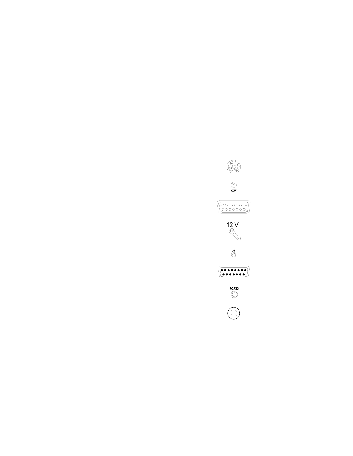
Item No. Item Function
1
Antenna socket.
2
Earth (ground) screw.
3
Automatic antenna control socket.
4
12V DC power lead.
5
External 8 ohm loudspeaker socket.
6
Remote control unit socket.
7
Serial-input socket used for programming
channels via an XP.
8
External alarm.
Page 16

Overview
2-8 9313 HF SSB transceiver
Figure 2.1: The control head front panel
Page 17

Overview
9313 HF SSB transceiver 2-9
Figure 2.2: The transceiver rear panel
Mounting cradle
6
5
Figure 2.3: The control head rear panel
G
Page 18

Overview
2-10 9313 HF SSB transceiver
Page 19

9313 HF SSB transceiver 3-1
3. Installation
On receipt of your transceiver, check the contents against the
packing list. Ensure all items are available before
commencing installation.
The following notes provide guidance to installation but are
not intended to be comprehensive procedures. It is
recommended that installation is carried out by qualified and
experienced personnel.
The installation (figure 3.1) typically consists of a 12V DC
power supply (battery) connected to the transceiver; the
antenna is connected to the transceiver with coaxial cable
and, for auto tuning antennas, with a control cable.
Coaxial
control
cable
and
9313 transceiver
12V Battery
Speaker
Microphone
Control head
Automatic tuning
whip antenna
Vehicle earth
Vehicle mounting
cradle
Figure 3.1: Typical mobile installation
Page 20

Installation
3-2 9313 HF SSB transceiver
Mounting the transceiver
In mobile installations, the transceiver must be mounted
in a position that will not cause injury to occupants in the
event of a motor vehicle accident.
Mount the transceiver and control head in a position
that allows:
•••• easy access to the control panel
•••• a free flow of air through the rear cooling fins.
There are two types of mounting cradles that can be used
when installing your transceiver:
• code 117 mounting cradle—front entry (normally
supplied with the 9313)
• code 118 mounting cradle—top/bottom entry.
Both types of cradle (supplied with 6 metres of DC power
cable) can be used to mount the transceiver. You must
determine the mounting position to best suit your needs.
Page 21

Installation
9313 HF SSB transceiver 3-3
Code 117 mounting cradle—front entry
Step Action
1.
The cradle can support the transceiver from above or below
permitting roof or floor mounting.
Secure the mounting cradle into position with the rotating
cam catches to the front. Ensure there is sufficient space at
the rear of the cradle to take the transceiver heat sink and
connectors.
2.
Align both cam catch slots with the T-section slides.
Cam catch
(Slot in line
with T slide
)
Front section
3.
Insert the transceiver side rails into the T-section slides and
push the transceiver fully into the cradle.
4.
Apply gentle pressure to the front panel of the transceiver
and lock into the cradle by turning the cam catches one
quarter of a turn in either direction with a suitable tool or
small coin.
G
Page 22

Installation
3-4 9313 HF SSB transceiver
Code 118 mounting cradle—top/bottom entry
Step Action
1.
Secure the mounting cradle into position with its spring clips
nearest the front. Ensure there is sufficient space at the rear
of the cradle to take the transceiver heat sink and connectors.
2.
Remove the front and rear fixing screws of the transceiver
side rails (the centre screw to be left untouched).
Note: Adaptor plates have to be fitted to the transceiver
side rails to secure the transceiver to the cradle.
3.
Secure the adaptor plates flush to the transceiver side rails
with the new screws provided, and fit one ‘O’ ring over each
projecting stud. The adaptor plates projecting studs fit into
the slides in the cradle.
4.
Insert the transceiver adaptor plate studs into the cradle
slides and push fully into the cradle.
5.
Secure the transceiver into the cradle with the spring clips.
G
Page 23

Installation
9313 HF SSB transceiver 3-5
Mounting the extended control head
The control head must be connected to the transceiver
before power is applied. Failure to do this may result in
damage to the transceiver in the following ways:
•••• the internal fuse blows and must be replaced
•••• the control head fails to operate. The power must be
disconnected from the transceiver and then
reconnected and switched on.
Step Action
1.
Remove the two cradle screws and washers securing the
mounting cradle to the control head.
2.
Secure the mounting cradle into position. Ensure there is
sufficient space at the rear of the cradle for the control cable.
3.
Secure the control head to the mounting cradle with the two
screws and washers.
4.
Mount the transceiver (refer to Mounting the transceiver on
page 3-2).
Page 24

Installation
3-6 9313 HF SSB transceiver
Step Action
5.
Connect the interface cable between the control head and
transceiver. Ensure the cable connectors are securely
fastened to the control head and the transceiver.
Notes: If necessary, remove the cover from one connector
to pass the cable through restricted openings.
If the cable is too long, gather the excess neatly at
one point.
6.
Connect the extension speaker cable to either the control
head or the transceiver.
G
Page 25

Installation
9313 HF SSB transceiver 3-7
Power supply
Ensure that the power supply to operate your transceiver is
12V DC.
All installations should be checked by a qualified technician
before power is applied to the transceiver.
The heavy duty six metre length of power cable—supplied
with the vehicle mounting cradle for mobile installations—
has been selected to minimise the voltage drop between the
battery and transceiver when in transmit mode. Installation
using a smaller core cable size is not recommended.
All cables should be protected from sharp edges and
mechanical abrasions.
For installation it is recommended that a suitable cartridge
fuse (32 Amp-accessory code 711) is fitted in the active
wire, close to the battery, to protect the power cable from the
possible risk of fire through damaged insulation coming in
contact with the vehicle chassis. Normal glass in-line
automotive fuses are not recommended. The transceiver is
fitted with adequate internal protection.
Connect the power cable between the transceiver and the
battery.
Note: In extended control installations where the
power and control cables are long and follow a
common path, keep the cables separated by at
least 200 mm. The cables can be brought
together for short distances, for example, to
pass through the same hole in a bulkhead.
Failure to observe this warning will cause
distortion of the transmitted audio signals.
G
Page 26

Installation
3-8 9313 HF SSB transceiver
Grounding
An adequate ground, or earth, is essential for satisfactory
operation of the transceiver.
A chassis ground or earthing position is provided on the rear
panel of the transceiver.
The control head should also be earthed.
G
Antennas
Correct installation of the antennas is of prime importance to
the operation of your transceiver.
To obtain the best performance and radiation efficiency from
your transceiver installation, it is important to consider the
physical location distance from the transceiver and earthing
of the antenna.
Detailed and specific installation instructions are provided
with each antenna.
G
Page 27

9313 HF SSB transceiver 4-1
4. Using the transceiver
This section covers the basic steps necessary to operate your
transceiver.
It outlines how you use the control buttons to make various
adjustments and settings, and includes transmitting and
receiving calls.
Throughout this section all displays show examples of
channel and frequency numbers. You must insert your
selected channel and frequency numbers as appropriate.
Unless otherwise stated, it is assumed throughout this section
that:
• the 12V DC power is supplied to your transceiver
• the control head On/Off button is switched on.
Refer to Switching the transceiver on or off on page 4-2.
Page 28

Using the transceiver
4-2 9313 HF SSB transceiver
Switching the transceiver on or off
When you switch the transceiver on, the display usually shows the last settings before
the transceiver was switched off. If your transceiver has a personal identification
number (PIN) allocated, then the display will request you to enter your PIN.
This section covers two methods of switching your transceiver on or off:
• switching on or off without a PIN
• switching on or off with a PIN
Switching on or off without a PIN
Step Action… Display shows… Remarks…
1.
Ensure power is
supplied to your
transceiver.
2.
Press
On/Off
You will see this display
for one second
and then the last channel
and frequencies selected
The Mute and Mode
indicators and the LCD
display illuminate.
The transceiver is turned
on and automatically set
to the last channel and
volume settings used.
3.
To switch off,
press
On/Off
The display and
indicators go off.
The transceiver is turned
off.
G
Page 29

Using the transceiver
9313 HF SSB transceiver 4-3
Switching on or off with a PIN
It is most important not to forget your PIN, otherwise you will never be able to switch
on your transceiver. If this happens, you will have to return your transceiver to Codan
for them to delete the allocated number.
Step Action… Display shows… Remarks…
1.
Ensure power is
supplied to your
transceiver.
2.
To switch on,
press
On/Off
You will see this display
for one second
and then this display
The Mute and Mode
indicators and the LCD
display illuminate.
3.
Use the numeric
buttons to enter
your PIN.
You must enter the
correct PIN, otherwise
your transceiver will
never turn on to the
operating mode.
4.
Press
Enter
B'con
The display is
automatically set to the
last channel and volume
settings used.
The transceiver is turned
on and can now be
operated.
5.
To switch off,
press
On/Off
The display and
indicators go off.
The transceiver is turned
off.
Page 30

Using the transceiver
4-4 9313 HF SSB transceiver
G
Page 31

Using the transceiver
9313 HF SSB transceiver 4-5
The transceiver display
The display provides you with visual indication of the selected channel numbers, and
the transmit and receive frequencies. In addition, it shows you messages that will
assist you when operating your transceiver. A detailed description of all the messages
can be found in Section 9, Display messages.
The display and button legends of the control head are back-lit to give you the
clearest view. If necessary, the brightness can be adjusted to suit your needs. Refer to
page 4-7, Dimming the display and indicators.
This section explains what the option codes mean and how to reveal the option codes
on the display.
The display contains two rows of information. Each row is split into three groups.
What you see in each group depends on the transceiver mode selected.
Option codes
Code Description
S
in the far left hand position indicates that selective call is
enabled for this channel.
E
indicates that emergency calling has been enabled for this
channel.
U
indicates the upper side band has been enabled for this
channel.
G
Page 32

Using the transceiver
4-6 9313 HF SSB transceiver
Displaying the channel option(s)
There are several channel options that you can select. The display button allows you
to check the options that have been selected at factory.
Step Action… Display shows… Remarks…
1.
Press
1
Disp
The option bar indicates
the options enabled for
the channel currently
selected.
There are six spaces in
the option bar that
contain either a code (see
Option codes) or an
underscore ( _ ). An
underscore indicates that
no function has been
enabled.
G
Page 33

Using the transceiver
9313 HF SSB transceiver 4-7
Dimming the display and indicators
The backlit display and indicators are at maximum brightness when you switch the
transceiver on. This procedure explains how to reduce the brightness of the display
and indicators.
Step Action… Display shows… Remarks…
1.
Press
2
Dim
This reduces the
brightness of the
indicators and dims the
display background
lighting. This function
does not work when you
are in numeric entry
mode. Only one dim
setting is available.
2.
To restore the
brightness, press
2
Dim
This restores both the
display and indicators to
their maximum
brightness. This function
does not work when you
are in numeric entry
mode.
G
Page 34

Using the transceiver
4-8 9313 HF SSB transceiver
Review the EPROM version and options
This facility allows you to review the EPROM version and some of the options fitted
to your transceiver.
This procedure is repeated in Section 9, Reviewing the EPROM program content.
Step Action… Display shows… Remarks…
1.
Ensure your
transceiver is
switched on.
2.
Press and hold
down
On/Off
.
.
.
:
:
.
At three second intervals
the display changes and
shows the following.
Displays lamp test—all
segments must be on and
all the indicators lit.
This shows the Program
(EPROM) type number
(example 90-20542-1).
Some indicator lamps
will turn off.
Program (EPROM) issue
number. This is an
example of EPROM
issue 5.10.
Page 35

Using the transceiver
9313 HF SSB transceiver 4-9
Step Action… Display shows… Remarks…
2.
cont.
Shows the number of
channels programmed by
the factory or agent. This
can be up to 15.
The display
indicates the
option fitted to
your transceiver.
d indicates that the
transceiver is inhibited
from entering transmit
frequencies from the
control head.
3.
Release
On/Off
This switches off your
transceiver.
G
Page 36

Using the transceiver
4-10 9313 HF SSB transceiver
Selecting channels
Using the Channel buttons
Step Action… Display shows… Remarks…
1.
Press either the up
or down arrow
Channel buttons
Channel
The channel number
selected appears in the
lower left hand corner of
the display, and the
transmit and receive
frequencies to the right.
Pressing these buttons
moves to the next higher
or lower channel. Keep a
button pressed to move
quickly through the
channels.
G
Page 37

Using the transceiver
9313 HF SSB transceiver 4-11
Adjusting the volume
This procedure tells you how to adjust the volume. When the mute is on, pressing
either of the volume buttons opens the mute for approximately one second. This
allows you to hear the background noise, thus assisting you to select the correct level.
When you switch your transceiver on, the volume level is at the last used setting.
Step Action… Display shows… Remarks…
1.
Press either the up
or down arrow
Volume buttons
Volume
The display does not
change.
Pressing this button
either increases or
decreases the volume.
You will hear a ‘pip’
when the volume control
has reached its operating
limit.
G
Page 38

Using the transceiver
4-12 9313 HF SSB transceiver
Using the clarifier
The clarifier buttons raise or lower the frequency in steps of 10 Hz. This allows you
to fine tune the transceiver to obtain the best clarity for received voice calls.
Step Action… Display shows… Remarks…
1.
Press either the up
or down arrow
Clarifier buttons
Clarifier
Adjust for the best clarity
using the Clarifier
button.
You will hear a ‘pip’
when the clarifier control
has reached its operating
limit.
Note: the clarifier resets
to the middle frequency
when you change
channels, or switch off.
G
Page 39

Using the transceiver
9313 HF SSB transceiver 4-13
Using the mute control
There are two mute functions on the transceiver:
• Voice—this function inhibits background noise until a voice signal is received.
• S’call—this function inhibits background noise until your transceiver has been
selectively called.
Voice mute
Step Action… Display shows… Remarks…
1.
To switch on and
off press
Mute
Voice
S'Call
The display does not
change.
The indicator is lit when
this option is selected.
Inhibits background
noise until a voice call is
received.
G
Selective call mute
Step Action… Display shows… Remarks…
1.
To switch on
press
Mute
Voice
S'Call
until the S’Call
indicator is lit.
The display does not
change.
The indicator is lit when
this option is selected.
Inhibits background
noise until a selective
call is received.
G
Page 40

Using the transceiver
4-14 9313 HF SSB transceiver
Tuning the antenna
Before using the selected channel, the antenna must be tuned to the transmission
frequency. The procedure used to tune the antenna depends upon the type of antenna
you are using. This may be:
• an automatic tuning whip antenna
• a multi-frequency tapped whip antenna.
Automatic tuning whip antenna
Step Action… Display shows… Remarks…
1.
Select the
required channel.
Refer to page 4-10,
Selecting channels.
2.
Press
Tune
If tuning was successful
If tuning was
unsuccessful
The Tx indicator will be
lit during this procedure.
You will hear ‘pips’
while the antenna is
tuning.
Once tuned successfully
you will hear two high
pitched ‘pips’.
If tuning is unsuccessful
you will hear two low
pitched tones. For further
information, refer to the
antenna handbook.
G
Page 41

Using the transceiver
9313 HF SSB transceiver 4-15
Multi-frequency tapped whip antenna
For specific details on how to use the antenna, refer to the relevant antenna handbook.
Step Action… Display shows… Remarks…
1.
Select the correct
tap on the antenna
to match the
transmit
frequency.
The display does not
change.
The antenna will either
have:
• the frequency
printed next to the
tap
• a number that
corresponds to a
frequency on the list
supplied with the
antenna.
G
Page 42

Using the transceiver
4-16 9313 HF SSB transceiver
Transmitting
It is important when transmitting to use the microphone to its best advantage. By
following the notes under Using the microphone you will obtain the best transmission
results. This section covers two topics:
• using the microphone
• transmitting a message.
Using the microphone
To connect the microphone to the transceiver, push the microphone plug gently into
the microphone socket and fasten the locking ring finger-tight. Do not over tighten.
Please observe the following notes when using the microphone.
• Hold the microphone front-on and close to your mouth.
• Press and hold down the PTT (Press To Talk) button.
• When starting a transmission, always state the call sign of the person you are
addressing and then your own call sign.
• Speak clearly at normal volume and rate.
• Use the word ‘over’ to indicate you have finished speaking and release the PTT
button.
• The transceiver has a ‘time out’ facility that stops the transmission after a pre-set
period. This facility prevents problems occurring if you have jammed the PTT
button down. The time out period can be adjusted to suit your requirements—
refer to Section 8, Changing the setup options.
G
Page 43

Using the transceiver
9313 HF SSB transceiver 4-17
Transmitting a message
Step Action… Display shows… Remarks…
1.
Select a channel
for transmission.
The display shows the
channel number and the
transmit (Tx) and receive
(Rx) frequencies.
Refer to page 4-10,
Selecting channels.
2.
Check the display
to see if the
channel transmit
frequency has
been enabled.
If the display shows
‘inhib’ then the channel
frequency is receive only.
If the channel has been
enabled, continue with
step 3.
If not and the display
shows ‘inhib’ then you
will have to select
another channel on which
to transmit.
3.
Tune the antenna. Refer to page 4-14,
Tuning the antenna.
4.
Listen and check
that the channel is
free from traffic.
Page 44

Using the transceiver
4-18 9313 HF SSB transceiver
Step Action… Display shows… Remarks…
5.
Press the PTT
button on the
microphone and
commence
talking.
Transmit your
message
following the
notes outlined in
Using the
microphone on
page 4-16.
The Tx indicator flashes
during transmission.
G
Page 45

Using the transceiver
9313 HF SSB transceiver 4-19
Page 46

9313 HF SSB transceiver 5-1
5. Using selective call
Selective call allows you to call an individual transceiver or a
group of transceivers. This can be likened to a normal telephone
system where the called station has a unique calling address or
number. However, the operator can also call a group of stations
if desired.
Each transceiver has its own identification number. The
identification number is a four digit code that you program into
the transceiver using the control head buttons.
The selective call feature operates by the transmission and
reception of coded signals. These signals contain the
identification number of the transceiver being called (the called
address) and the number of the transceiver making the call (the
self-identification).
All displays in this section show examples of channel and
frequency numbers. You must insert your selected channel and
frequency numbers.
Page 47

Using selective call
5-2 9313 HF SSB transceiver
Selective call terms
The following terms are used in this section.
This term… Means…
Decoding Receiving and translating the encoded message.
Encode The translation of the identification number and instructions
into a coded message for transmission.
Group call A call to all transceivers within a selected group. For
example, a call using the identification address 0200 (group
call) will be received by all transceivers whose identification
address falls in the two hundred digit range (0201 to 0299).
Preamble Part of the coded selective call message structure which is
transmitted when you press the Call button. The message
contains the preamble tone which precedes the called
address and the self-identification address codes.
Program Setting the identification addresses into the transceiver.
Revertive Signal A signal automatically transmitted back from the receiving
transceiver to indicate message received and decoded
satisfactorily.
This signal does not apply to group calls.
Selective beacon
call
A call used to check signal conditions to a selected station.
Page 48

Using selective call
9313 HF SSB transceiver 5-3
This term… Means…
Self-identification The four digit identification number of the calling
transceiver.
Station A term used for the location of a transceiver, either mobile
or fixed based.
G
Page 49

Using selective call
5-4 9313 HF SSB transceiver
Setting up selective call
There are several features that need to be set up before selective
call is used:
• the preamble time period
• the called address
• the self-identification address
• the 99 beacon.
You may cancel the procedure at any time by turning the
transceiver off. Turning the transceiver off stores any changes
you made to the features.
Once you have commenced this procedure, if no action is
required you can skip through all the features by repeatedly
pressing the Call button.
Notes: A long preamble is required when scanning selective
calls.
The reason for a long preamble is that during
scanning, the preamble has to be present throughout
the time it takes to scan all eight selective call
channels.
Do not use identification addresses ending in ‘00’ and
‘99’ as they are used for the group call and beacon
facilities.
You must always enter information within 60 seconds
of pressing the Enter button, otherwise the transceiver
reverts back to the normal mode.
Page 50

Using selective call
9313 HF SSB transceiver 5-5
Setting the preamble time period
Step Action… Display shows… Remarks…
1.
Ensure your
transceiver is
switched off.
2.
Hold down
Call
and press
On/Off
Hold the Call button
down for approximately
three seconds.
This turns the transceiver
on and into the preamble
setup mode.
3.
Press
Channel
to set the
preamble length.
or
Pressing the or
buttons alternates
between a long or short
preamble.
4.
Press
Enter
B'con
Once enter has been
pressed, the preamble
time has been set and can
only be changed by
repeating this procedure.
If your transceiver has
the preset selective
calling switches fitted,
proceed to step 6.
Page 51

Using selective call
5-6 9313 HF SSB transceiver
Setting the fixed called address
There are two ways of entering the called address:
a) as below, which is fixed and cannot be changed easily
b) by the method used on page 5-11, Transmitting a selective call (Open
access selective call) which allows the address to be entered from the front
panel and is easy to change to call another transceiver.
Note: by setting a fixed called address the normal function of Call will
change. If a fixed call address has been set, pressing Call will
automatically send the programmed address. Open access selective
calling is disabled.
Step Action… Display shows… Remarks…
5.
Use the numeric
buttons to enter
the called address
number.
To delete an
address, enter four
zeros.
You can override an
existing address by
entering a new number.
6.
Press
Enter
B'con
Once Enter has been
pressed, the called
address has been set and
can only be changed by
repeating this procedure.
The next step must be
completed within 60
seconds.
Page 52

Using selective call
9313 HF SSB transceiver 5-7
Setting the self-identification address
Step Action… Display shows… Remarks…
7.
Use the numeric
buttons to enter
the selfidentification
address number.
To delete an
address, enter four
zeros.
You can override an
existing address by
entering a new number.
8.
Press
Enter
B'con
Once Enter has been
pressed, the selfidentification address has
been set and can only be
changed by repeating this
procedure.
The next step must be
completed within 60
seconds.
Enabling the beacon mode
Step Action… Display shows… Remarks…
9.
Press
Channel
to switch the
beacon on or off.
or
Repeatedly pressing the
or buttons
switches the beacon on
and off.
For more information on
this feature, refer to page
5-20, Using the beacon
feature.
G
Page 53

Using selective call
5-8 9313 HF SSB transceiver
Checking if a channel is enabled for selective call
A channel must be enabled for the selective call facility to operate. If the channel you
wish to use has not been enabled, please contact your Codan dealer.
Step Action… Display shows… Remarks…
1.
Press and hold
1
Disp
An S in the left hand
position of the options
bar indicates that the
channel is enabled for
selective calling.
2.
Release
1
Disp
The display will return to
its original display in
approximately one
second.
G
Page 54

Using selective call
9313 HF SSB transceiver 5-9
Selective call mute enable or inhibit
This facility enables or inhibits the operation of the S’call Mute function. When S’call
Mute is inhibited, you cannot operate selective call mute.
Step Action… Display shows… Remarks…
1.
Turn the
transceiver off
and move the
front panel link to
position 1.
No display. Before moving the link,
note its original position.
Refer to Section 8,
Changing the position of
the control head link.
2.
Hold down
Mute
Voice
S'Call
and press
On/Off
Hold the Mute button
down until the display
shows
Repeatedly pressing
Mute will switch between
Enable and inhib
(inhibit).
3.
Press
Mute
Voice
S'Call
Stop at the selection you
require.
4.
Press
On/Off
No display. The transceiver is now
switched off.
Page 55

Using selective call
5-10 9313 HF SSB transceiver
Step Action… Display shows… Remarks…
5.
Return the control
head link to its
original position
E.
Refer to Section 8,
Changing the position of
the control head link.
6.
Replace the cover
before switching
on your
transceiver.
G
Page 56

Using selective call
9313 HF SSB transceiver 5-11
Transmitting a selective call
For selective call to operate you must have your self-identification number
programmed, refer to Setting the self-identification address on page 5-7.
Step Action… Display shows… Remarks…
1.
Select the
channel.
Ensure the channel is
enabled for selective
calls.
Press the ‘Disp’ button to
view the enabled options.
2.
Press
Mute
Voice
S'Call
to turn the Mute
button to the off
position.
The display does not
change.
The indicator turns off
and you hear background
noise.
3.
Press
Call
The screen displays the
4-digit address of the
station you last called on
this channel (1374 in this
example).
No address is displayed
if this channel has never
been used for making
selective calls.
If the address is correct,
go to step 5.
Page 57

Using selective call
5-12 9313 HF SSB transceiver
Step Action… Display shows… Remarks…
4.
Use the numeric
buttons to enter
the address of the
station you want
to call.
In this example, you are
calling station 1144.
5.
Check that the
channel is free
from traffic.
The display does not
change.
Listen for approximately
10 seconds to ensure the
channel is free.
If the channel is busy,
wait until the channel is
free or try another
channel.
6.
Press
Call
The display does not
change.
The Tx indicator is lit
and you hear a ‘warbling’
sound for approximately
10 seconds.
7.
If the other station
received your call
successfully, you
hear the short
tones of the
revertive signal
after a few
seconds.
You hear nothing if this
is a group call.
You can now speak to
the other station.
G
Page 58

Using selective call
9313 HF SSB transceiver 5-13
Receiving a selective call
Step Action… Display shows… Remarks…
1.
No action. The
transceiver
automatically
completes this
event.
When you receive a call
the display changes to
show you the selfidentification address of
the calling station.
When you receive a call,
tones will be heard on the
loudspeaker.
You will hear a series of
three telephone rings for
selective calls, and 16
short ‘beeps’ for group
calls.
Notes: On receipt of a call you have two options:
• either answer it immediately. Refer to Answering a received call on
page 5-15
• let the transceiver automatically store the caller’s self-identification
number in memory to await your reply, refer to Returning a received
call on page 5-16.
If your transceiver was unattended at the time the selective call was
received, the callers self-identification number is stored in memory for
you to review at a later time. Refer to Reviewing the list of received calls
in memory on page 5-17.
If you do not answer the call immediately, once the call is stored in
memory your transceiver will continue to give out ‘pips’ every four
seconds to indicate that a call has been received. If you wish to silence
these ‘pips’, yet still retain the display, press the ‘Disp’ button.
If you only wish to receive selective calls, ensure the S’Call Mute
indicator is lit.
Page 59

Using selective call
5-14 9313 HF SSB transceiver
Notes:
(cont.)
If the microphone PTT button is not pressed before the end of the tones:
• the called display will remain on to indicate that a call was received
• a ‘pip’ will be heard every four seconds
• the external alarm relay contacts will close for approximately two
minutes (refer to page 5-26, Using the external alarm feature).
G
Page 60

Using selective call
9313 HF SSB transceiver 5-15
Answering a received call
This procedure is used when you want to answer a call that has just been received
while your transceiver is still producing a ringing tone.
Step Action… Display shows… Remarks…
1.
The display shows
the channel
number and the
identification
address of the
caller.
2.
Press the
microphone PTT
button twice in
succession.
The display either reverts
back to the normal
display or shows the
details of the next (if
any) unanswered calls.
The first press of the
PTT button cancels the
call and the S’call mute.
The second press of the
PTT button allows you to
transmit to the caller.
G
Page 61

Using selective call
5-16 9313 HF SSB transceiver
Returning a received call
This procedure is used when you want to return a call that has been stored in the
memory stack.
Step Action… Display shows… Remarks…
1.
Select the call you
wish to return.
If necessary, tune
the antenna.
The display shows the
channel number and the
identification address of
the caller.
Refer to Reviewing the
list of received calls in
memory on page 5-17.
2.
Press
Call
The call details are now
deleted from memory,
but ready to transmit.
3.
Check that the
channel is free
from traffic, then
press
Call
The display shows the
details of the next
unanswered call.
The transceiver sends the
selective call and the
transmit indicator will
light.
If the call is answered,
proceed to use the
transceiver in the normal
way.
The caller details are
deleted when you press
the PTT button on the
microphone.
G
Page 62

Using selective call
9313 HF SSB transceiver 5-17
Reviewing the list of received calls in memory
Your transceiver is able to record up to 10 calls in memory from various stations.
These may be on different channels if your transceiver is in scan mode. These calls
are recorded in a memory stack awaiting your review. If a station calls more than once
on the same channel, your transceiver only records one of the calls. If more than 10
calls are made to your transceiver, the first call stored in memory is deleted to make
room for the latest call.
Ensure your transceiver is not in the scan mode before commencing this procedure.
A loss of power to your transceiver will delete information stored in memory.
Ensure you record or use all the information stored in the memory stack before
switching off the transceiver.
Notes: If the transceiver power is lost momentarily (such as during starting the
vehicle engine), the call memory is retained but the number is lost.
Switching the transceiver off using the On/Off button deletes all calls
stored in the memory stack.
The Disp button is used to review the list of received calls held in the memory.
Page 63

Using selective call
5-18 9313 HF SSB transceiver
Reviewing calls held in memory
This procedure allows you to review all calls held in the memory in the order
received. Ensure the transceiver is not in scan mode when reviewing the list of
selective calls received.
If no calls have been made to your transceiver, the display will continue to show both
the channel and frequency numbers.
Step Action… Display shows… Remarks…
1.
No action, this is
what you will see
on the display of
your transceiver.
If your transceiver
is scanning, and
as it is not on the
channel that
called, the display
will show
‘CALd’.
The last call recorded
will be shown in the
display.
2.
To view the calls
held in memory,
press
1
Disp
twice within one
second.
The first station to call
will be displayed first.
The display shows the
callers identification
code (1374) and the
channel used (3).
Page 64

Using selective call
9313 HF SSB transceiver 5-19
Step Action… Display shows… Remarks…
3.
Press either the up
or down arrow
Channel buttons
Channel
Pressing will
change the display to
show the next call, and
will reverse the
order viewed. The
identification address and
corresponding channel
number will change for
each caller.
4.
If you wish to
return a call, refer
to Returning a
received call on
page 5-16.
5.
To delete a call,
press the PTT
button on the
microphone.
The display will show the
next caller’s details.
When you press the PTT
button, the identification
number in the display is
deleted from memory.
You can then select, call
or clear the remainder of
the calls from memory.
6.
If you don’t clear
all the calls, the
display will show
‘CALd’ until
memory is empty.
If you are on the channel
where the call was
recorded, the display
shown in step 1 will be
on view.
7.
Press
1
Disp
The display shows the
standard display.
This returns the
transceiver to normal
operation.
G
Page 65

Using selective call
5-20 9313 HF SSB transceiver
Using the beacon feature
The beacon facility is used to check signal conditions
between two transceivers fitted with selective call.
The beacon facility has two modes of operation:
• selective beacon mode
• base station (99) beacon mode.
Selective beacon mode
With the beacon facility enabled on a transceiver, it will
transmit a beacon signal on receipt of a selective beacon call
from another transceiver. Refer to the Selective beacon mode
procedure on page 5-22.
Both transceivers must be on the same channel, or the
receiver of the selective beacon call must be scanning
through the same channel.
(99) beacon mode
The 99 beacon mode is recommended for use in base station
applications and for those transceivers that may have
operating selective call but do not have the beacon mode
facility.
With a base station enabled for beacon mode, it will transmit
a beacon signal on receipt of a selective call ending in 99.
Refer to the (99) beacon mode procedure on page 5-24.
The thousand and hundred digits of the address must be the
same for both the beacon transmitting and receiving stations.
If mobile transceivers have the beacon enabled, the first two
digits of each mobile transceiver’s self-identification address
should be set to a different number so that they do not all
transmit a beacon response together.
Page 66

Using selective call
9313 HF SSB transceiver 5-21
General information for both modes of operation
The beacon signal consists of four long tones.
Self-identification addresses ending in 99 should be avoided
as these will cause confusion.
No alarm or call is recorded at the receiving transceiver,
only the Tx indicator flashes.
If the receiving transceiver is in scan mode, the scan
sequence recommences immediately.
Normal selective call operation is not affected.
Page 67

Using selective call
5-22 9313 HF SSB transceiver
Selective beacon mode
Step Action… Display shows… Remarks…
1.
Ensure your
transceiver is
switched on.
The last channel selected.
2.
Select the
required test
channel and tune
the antenna.
Refer to Section 4,
Selecting channels.
3.
Press
Enter
B'con
When this button is
pressed, the S’call Mute
is automatically switched
off.
4.
Use the numeric
buttons to enter
the required
selective call
address number.
This allows you to send a
selective call to a station
whose address number is
1374.
Page 68

Using selective call
9313 HF SSB transceiver 5-23
Step Action… Display shows… Remarks…
5.
Check that the
channel is free
from traffic, then
press
Call
Immediately when the
call is received, the
display shows the last
channel, transmit and
receive frequencies used.
The transmit indicator
will be lit and you will
hear a warbling sound for
approximately 10
seconds. If the call is
successfully decoded you
will hear four long
revertive tones.
You can check these
tones for signal strength
and compare them with
signal strengths from
other channels. Select the
channel giving the best
return signal strength.
G
Page 69

Using selective call
5-24 9313 HF SSB transceiver
(99) beacon mode
Step Action… Display shows… Remarks…
1.
Ensure your
transceiver is
switched on.
The last channel selected.
2.
Select the
required test
channel and tune
the antenna.
Refer to Section 4,
Selecting channels.
3.
Press
Call
When this button is
pressed, the S’call Mute
is automatically switched
off.
4.
Use the numeric
buttons to enter
the required
selective call
number. Use the
first two digits of
the stations self
identification
number and
ensure the last two
are 99.
This will send a signal to
the base station enabled
for beacon call, whose
four digit selfidentification address
begins with 13.
Page 70

Using selective call
9313 HF SSB transceiver 5-25
Step Action… Display shows… Remarks…
5.
Check that the
channel is free
from traffic, then
press
Call
Immediately after the call
is received, the display
shows the last channel,
transmit and receive
frequencies used.
The transmit indicator
will be lit and you will
hear a warbling sound for
approximately 10
seconds. If the call is
successfully decoded you
will hear four long
revertive tones.
You can check these
tones for signal strength
and compare them with
signal strengths from
other channels.
Select the channel giving
the best return signal
strength.
G
Page 71

Using selective call
5-26 9313 HF SSB transceiver
Using the external alarm feature
If your transceiver has option SD fitted, an external alarm
facility is made available through the external alarm socket
on the rear panel (refer to figure 2.2).
A pair of relay contacts are wired to the socket, which close
for two minutes when your transceiver receives a selective
call. The relay contacts can be used to operate an alarm bell
or buzzer.
• Relay contact rating: 50V DC, 1 Amp
• Plug connections: pins 2 and 3.
Further details on the socket can be found in Section 10.
These contacts must not be used to switch voltages
greater than 50V, or loads that draw more than 1 Amp.
G
Page 72

9313 HF SSB transceiver 6-1
6. Using the receiver in scan mode
In the receiver scan mode your transceiver is able to listen
into selected channels for transmitted signals. Once a signal
has been detected, the transceiver holds that channel for a
pre-selected time before continuing with the scan. This is
determined at setup.
In normal operating conditions, a maximum of 15 channels
can be programmed to be scanned in sequence for audio
(voice) signals. A maximum of 8 selective call channels can
also be included but must be programmed within the first
eight entries.
The scanning facilities can only be used with a suitable
antenna system. Mobile installations require a Codan
automatic tuning whip antenna.
It is assumed that before you use any of the procedures in
this section, you have turned on the transceiver unless
otherwise requested.
All displays in this section show examples of channel and
frequency numbers. You must insert your selected channel
and frequency numbers.
G
Page 73

Using the receiver in scan mode
6-2 9313 HF SSB transceiver
Setting up the scan mode
The scan program allows your transceiver to scan a selected number of frequencies.
Your transceiver also has the option to run in normal or Auto-scan mode. The Autoscan mode automatically puts the transceiver back into scan after five minutes of
inactivity (such as no channel change, PTT, tune etc.). These scan facilities have two
options:
• Enabled—scan programs can be entered and deleted from the control head.
• Inhibit—scan programs cannot be entered or deleted from the control head.
The transceiver has to be turned off before you start this procedure.
Step Action… Display shows… Remarks…
1.
Hold down
Scan
and press
On/Off
Hold down the Scan
button until the display
shows
This turns the transceiver
on, and into the scan
setup mode.
2.
Press
Scan
Each press of the Scan
button scrolls to the next
option.
If this is the option you
want, go to step 6.
3.
Press
Scan
Switches to Auto option.
If this is the option you
want, go to step 6.
Page 74

Using the receiver in scan mode
9313 HF SSB transceiver 6-3
Step Action… Display shows… Remarks…
4.
Press
Scan
Pressing the Scan
button again
returns you to the
display in step 1.
Switches from inhib to
Enable.
Note: If you select automatic scanning, you now have the option of
selecting Selective Call Mute to be enabled as soon as you
enter the automatic scan mode. If you wish to select this option
then continue with step 5, if not, go to step 6.
5.
Press
Mute
Voice
S'Call
The display does not
change.
The S’Call indicator is
lit.
You have now selected
selective call mute to be
enabled as soon as you
enter the automatic scan
mode.
6.
Press
On/Off
No display. Your selection has been
made and the transceiver
is now switched off.
G
Page 75

Using the receiver in scan mode
6-4 9313 HF SSB transceiver
Programming the channels to be scanned
In normal operating conditions, a maximum of 15 channels can be programmed to be
scanned in sequence for audio (voice) signals. Channels required to operate on a
selective call must be programmed within the first eight entries.
Ensure your transceiver is switched on and scan program has been enabled.
Step Action… Display shows… Remarks…
1.
Press
Enter
B'con
and then
Scan
within one
second.
The Scan indicator
flashes.
Any previous channels
programmed to be
scanned will be erased.
2.
Select the relevant
channel.
Press
Channel
Refer to Section 4,
Selecting channels.
Channels required to
operate on selective call
must be enabled.
Page 76

Using the receiver in scan mode
9313 HF SSB transceiver 6-5
Step Action… Display shows… Remarks…
3.
Press
Scan
The channel is
programmed for
scanning.
Repeat this procedure
until all channels you
want to scan have been
programmed.
4.
Press
Enter
B'con
and then
Scan
within one
second.
The channels you have
programmed are now set
within the transceiver.
Notes: If an error is made, the programming mode must be switched off (follow
step 4), and the procedure repeated.
If you try to program more than 15 entries, you hear a single low-pitched
tone and the error message ‘scan full’ displays.
The channel entries can be reviewed while in the scan programming mode.
Use the channel button to scroll through the channels. Any channel in the
scan program is indicated by ‘prog’ on the display (as shown in step 3
above).
The scan program can be inhibited, refer to Setting up the scan mode on
page 6-2.
G
Page 77

Using the receiver in scan mode
6-6 9313 HF SSB transceiver
Receiving in scan mode
This procedure covers three topics when receiving in scan mode:
• start scanning
• stop scanning
• changing the scan mode.
Start scanning
Step Action… Display shows… Remarks…
1.
Press
Scan
The display shows details
of each channel as it is
scanned.
The Scan indicator will
be displayed during
scanning.
Notes: You cannot transmit while the transceiver is in the scan mode. If you
attempt to transmit, you will hear a single ‘pip’ and the error message
‘No PTT Error’ will be displayed.
If you need to transmit, you must stop the scanning operation.
G
Stop scanning
Step Action… Display shows… Remarks…
1.
Press
Scan
or press the
microphone PTT
button twice in
succession.
The display shows the
last channel scanned.
The Scan indicator is no
longer displayed.
Note: If you only press the PTT button once, the display shows ‘NO PTT Error’
G
Page 78

Using the receiver in scan mode
9313 HF SSB transceiver 6-7
Changing the scan mode
There are three voice scan mode options available to you which can be selected by
repeatedly pressing the Mute button. Your transceiver must be in scan mode to
complete this operation (refer to Receiving in scan mode on page 6-6).
• Pause scanning. Scanning stops for five seconds when an audio signal is detected.
• Hold scanning. Scanning stops when an audio signal is detected, and continues
only when the signal ceases.
• Continuous scanning. Each channel is monitored for one second. Scanning
continues regardless of any audio signals being detected.
Note: scan modes operate for both voice and selective call reception
Step Action… Display shows… Remarks…
1.
Ensure the
transceiver is in
the Scan mode.
The display shows the
frequencies as they are
scanned.
The Scan button
indicator will be lit in the
Scan mode.
Refer to Receiving in
scan mode on page 6-6.
2.
Pause scanning
Press once
Mute
Voice
S'Call
You will hear a single
‘pip’ and the Voice
indicator will be lit.
If you want Hold
scanning, go to step 3.
To exit this mode go to
step 5.
Page 79

Using the receiver in scan mode
6-8 9313 HF SSB transceiver
Step Action… Display shows… Remarks…
3.
Hold scanning
Press again
Mute
Voice
S'Call
You will hear two ‘pips’
and the Voice indicator
will be lit.
If you want Continuous
scanning, go to step 4.
To exit this mode go to
step 5.
4.
Continuous
scanning
Press again
Mute
Voice
S'Call
You will hear a single
‘pip’ and the Voice
indicator will be off.
5.
To exit this mode,
press
Scan
G
Page 80

Using the receiver in scan mode
9313 HF SSB transceiver 6-9
Using selective call in scan mode
Selective call scanning ensures that you are only alerted when the incoming calls are
specifically addressed to you.
This facility also allows the transceiver to store in memory the addresses of up to ten
stations that may have tried to contact the transceiver whilst it was unattended. These
addresses may have been transmitted over any of the programmed channels.
The first eight channels of the scan are used for selective call scanning.
For networks using this facility, it is important for the calling station to transmit a
long preamble. For more details on selective calling, refer to Section 5, Using
selective call.
Step Action… Display shows… Remarks…
1.
Press
Scan
The display shows each
channel as it is scanned.
The Scan indicator will
be lit.
2.
Press
Mute
Voice
S'Call
button until S’Call
indicator is lit.
On detection of a call,
scanning stops until the
call is decoded. If the
call is addressed to your
transceiver you will hear
a series of three
telephone rings followed
by ‘pips’ every four
seconds.
If the call is not
addressed to your
transceiver, the scan
continues.
Page 81

Using the receiver in scan mode
6-10 9313 HF SSB transceiver
Step Action… Display shows… Remarks…
3.
If the call is
addressed to the
transceiver the
display changes.
Every time an
addressed call is
detected, the
display will repeat
the same message
with the
appropriate
channel
frequency.
If the call is not answered
immediately, the
scanning stops for 2½
minutes and you will
hear ‘pips’ every 4
seconds.
After this period of time
the transceiver carries on
scanning.
4.
To stop scanning
press
Scan
The scan indicator longer
displays.
G
Page 82

RFDS and Telstra services
9313 HF SSB transceiver 7-1
7. RFDS and Telstra services
This section describes how you can use your 9313
transceiver to access the following remote area safety
organisations:
• the Royal Flying Doctor Service (RFDS)
• Telstra (formerly OTC).
It briefly covers the services offered by each organisation
and details the procedures required to use these services.
Selected channel frequencies for both services should be
programmed into the transceiver. Make sure the frequencies
are effective for operation in the area you will be in.
Page 83

RFDS and Telstra services
7-2 9313 HF SSB transceiver
The Royal Flying Doctor Service
The Royal Flying Doctor Service (RFDS) is a vital communications link in the
Australian outback. Apart from maintaining contact and a listening watch for medical
services, the organisation also provides general communication facilities which
includes radiotelephone and lettergram services.
Each base station is allotted with a unique range of channel frequencies, some of
which may be used to provide a day and night communications watch for medical aid
and assistance.
It is most important before making a trip, or entering into an area covered by a base
station, that the listening watch frequencies and operating times are known. Your
transmission may never be heard if you have chosen the wrong channel to make a call
for help.
How to contact the RFDS
To contact an RFDS base station, select the station primary frequency and tune the
antenna. Before transmitting, check that the channel is not being used and follow the
procedure in section 4, Transmitting.
Emergency communications
Each RFDS base station has its own specified times for routine medical consultation.
If during normal RFDS base station hours medical advice is required and cannot wait
until the routine medical session, you should:
• wait until the first quiet moment on the frequency
• transmit and call the base station by call sign, give your own call sign and
mention that this is an urgent medical call.
Page 84

RFDS and Telstra services
9313 HF SSB transceiver 7-3
On receipt of this call, the RFDS base station will deal only with the outstation
seeking medical advice. If the frequency is heavily congested with traffic and there
are no quiet periods, the above medical call should be preceded by a 20 second RFDS
emergency alarm call.
If medical assistance is required at a time when the RFDS base station is normally
closed, at night or at weekends, follow the procedure on page 7-4, Making an RFDS
emergency call.
If the RFDS base station has heard your call it will respond within two minutes with a
transmitted tone – you can be assured that either the local hospital or police station
has been notified that you are in need of assistance. RFDS staff will respond within
five minutes of the call being transmitted and will ask the station making the
emergency call to identify itself. You must then respond by following the procedure
Making an RFDS emergency call on page 7-4.
RFDS and St Johns Ambulance Stations
Control Station Call Sign Telephone
Alice Springs VJD (089) 52 1033
Broken Hill VJC (080) 88 0777
Cairns VJN (070) 53 1952
(070) 53 1954
Carnarvon VJT (099) 41 1758
Charleville VJJ (076) 54 1233
Derby VJB (091) 91 1211
Kalgoorlie VJQ (090) 21 2211
Meekatharra VKJ (099) 81 1107
Mount Isa VJI (077) 43 2800
Port Augusta VNZ (086) 42 2044
Port Hedland VKL (091) 73 1386
St Johns (Darwin) VJY (089) 45 2455
G
Page 85

RFDS and Telstra services
7-4 9313 HF SSB transceiver
Making an RFDS emergency call
The RFDS Call button is used in Australia to call the Royal Flying Doctor Service.
This button will only function if the selected channel is enabled for emergency calls.
Step Action… Display shows… Remarks…
1.
Select the correct
RFDS channel for
the base station
required, then
tune the antenna.
Refer to section 4,
Tuning the antenna.
2.
Press and hold
RFDS
Call
Hold down the
button until the
emergency tone
starts after the two
seconds of ‘pips’.
The ‘pips’ warn you that
the call is about to be
made. If you release the
button before the
emergency tone starts, no
call is made.
The emergency tone
continues for 20 seconds.
During this period the Tx
indicator is lit.
3.
If you hear a
single low pitched
beep and the
display shows
‘Not Enable’, the
channel is not an
RFDS frequency
and cannot be
used for an
emergency call.
Try again and select a
correct RFDS channel.
Page 86

RFDS and Telstra services
9313 HF SSB transceiver 7-5
Step Action… Display shows… Remarks…
4.
Wait for a reply
before
transmitting your
message.
The display does not
change.
If the call was received
by an attended RFDS
base, they will reply
immediately.
If the call was received
by an unattended RFDS
base, they will transmit a
tone within two minutes.
If the tone call is not
received, you should try
again or go to another
channel.
5.
To cancel a call
during the 20
second
transmission time
either press
Tune
,
the PTT switch on
the microphone or
the
On/Off
button.
G
Page 87

RFDS and Telstra services
7-6 9313 HF SSB transceiver
Telstra Radphone Service
Telstra Mobile Satellite and Radio Services (formerly OTC Maritime) provide the
9313 transceiver user with the ability to access the public switched telephone network
(PSTN) at any time of the day or night. This brings the convenience of home or office
to the outback traveller through the radio telephone facility of your transceiver and
the Telstra organisation. Calls can be transmitted or received just like a normal
telephone.
The services provided by Telstra include:
• Radphone Direct Dial for direct dialling (service not available to 9313
users)
• Radphone Selcall operator connected telephone calls for registered
selcall users
• Radphone operator connected for non-registered selcall users.
To register for ‘Radphone Selcall’ and for details of other Telstra services, you are
recommended to contact the Telstra Customer Service Centre on Freecall 1800 810
023 or (02) 901 2103.
Calling a Telstra station can be accomplished using the selective call facility (which is
recommended) or by voice on the appropriate Telstra channel.
It is most important that the correct frequency is selected for initial contact with a
Telstra station as a listening watch is only kept on the ‘voice calling’ channels.
For further reading and information you are recommended to obtain a copy of the
Telstra ‘Radphone Users Guide’.
G
Page 88

RFDS and Telstra services
9313 HF SSB transceiver 7-7
Transmitting a Telstra selective call
This procedure explains how to contact a Telstra station selectively to initiate a
telephone call through the Telstra Radphone operator using the ‘Radphone Selcall’
and ‘Radphone’ services.
It is assumed your transceiver has been programmed with your self-identification
number issued by Telstra Customer Service Centre.
Ensure your transceiver is switched on before commencing this operation and the
antenna is tuned on the selected monitored (selcall) channel, refer to Tuning the
antenna in section 4.
Before making a telephone call, it is often beneficial to make a beacon call to assess
the best channel to use. Refer to Transmitting a Telstra beacon call on page 7-10.
Step Action… Display shows… Remarks…
1.
Select the
channel.
Ensure the channel is
enabled for selective
calls.
Press the ‘Disp’ button to
view the enabled options.
2.
Press
Mute
Voice
S'Call
to turn the Mute
button to the off
position.
The display does not
change.
The indicator turns off
and you hear background
noise.
Page 89

RFDS and Telstra services
7-8 9313 HF SSB transceiver
Step Action… Display shows… Remarks…
3.
Press
Call
The screen displays the
4-digit address of the
station you last called on
this channel (1374 in this
example).
No address is displayed
if this channel has never
been used for making
selective calls.
If the address is correct,
go to step 5.
4.
Use the numeric
buttons to enter
the address of the
Telstra station you
want to call (see
table below).
In this example, you are
calling the Telstra station
in Brisbane.
5.
Check that the
channel is free
from traffic.
The display does not
change.
Listen for approximately
10 seconds to ensure the
channel is free.
If the channel is busy,
wait until the channel is
free or try another
channel.
6.
Press
Call
The display does not
change.
The Tx indicator is lit
and you hear a ‘warbling’
sound for approximately
10 seconds.
Page 90

RFDS and Telstra services
9313 HF SSB transceiver 7-9
Step Action… Display shows… Remarks…
7.
If the Telstra
station received
your call
successfully, you
hear the short
tones of the
revertive signal
after a few
seconds.
You can now speak to
the Telstra station.
Note: If the call is not successful, either the channel chosen is not a monitored or
selcall channel for the Telstra station called, or the frequency is not
appropriate for the time of day and range you are working. Check the
channel frequencies listing for the station being called, if necessary choose
another channel.
The Telstra station address numbers
Brisbane 104
Darwin 105
Melbourne 106
Perth 107
Sydney 108
Townsville 109
G
Page 91

RFDS and Telstra services
7-10 9313 HF SSB transceiver
Transmitting a Telstra beacon call
The beacon facility is used to check signal conditions between your transceiver and a
selected Telstra station. For the purpose of calling Telstra, the selective beacon mode
is used.
Step Action… Display shows… Remarks…
1.
Ensure your
transceiver is
switched on.
The last channel selected.
2.
Select the
required test
channel and tune
the antenna.
Refer to Section 4,
Selecting channels.
3.
Press
Enter
B'con
When this button is
pressed, the S’call Mute
is automatically switched
off.
4.
Use the numeric
buttons to enter
the required
selective call
address number of
the Telstra station
(see table below).
This example shows the
Telstra station address
for Brisbane.
Page 92

RFDS and Telstra services
9313 HF SSB transceiver 7-11
Step Action… Display shows… Remarks…
5.
Check that the
channel is free
from traffic, then
press
Call
Immediately when the
call is received, the
display shows the last
channel, transmit and
receive frequencies used.
The transmit indicator
will be lit and you will
hear a warbling sound for
approximately 10
seconds. If the call is
successfully decoded you
will hear four long
revertive tones.
You can check these
tones for signal strength
and compare them with
signal strengths from
other channels. Select the
channel giving the best
return signal strength.
The Telstra station address numbers
Brisbane 104
Darwin 105
Melbourne 106
Perth 107
Sydney 108
Townsville 109
G
Page 93

RFDS and Telstra services
7-12 9313 HF SSB transceiver
Receiving a Telstra selective call
This procedure explains how a telephone call is received on your transceiver through
Telstra from the public telephone service.
It should be noted that telephone subscribers can book a radio–telephone call to you
by dialling the national Telstra booking number 0108.
Calls will only be decoded if your transceiver is switched on and in either the:
• selective call scan mode (refer to section 6, Using selective call in scan mode)
which is recommended when expecting a call
• set on the correct channel for the time of day and the antenna is tuned on the
selected channel, refer to Tuning the antenna in section 4.
Step Action… Display shows… Remarks…
1.
No action, the
transceiver
automatically
completes this
event.
The display shows that
you have received a
Telstra call and the
address of the calling
station.
This is an example of a
Telstra call from the
Brisbane station with
selcall ident number 104.
Notes: On receipt of a call you have two options:
• either answer it immediately, refer to Answering a received call in
section 5
• let the transceiver automatically store the callers self identification
number in memory to await your reply, refer to Returning a received
call in section 5.
If your transceiver was unattended at the time the selective call was
received, the callers self identification number is stored in memory for
you to review at a later time. Refer to Reviewing the list of received calls
in memory in section 5.
Page 94

RFDS and Telstra services
9313 HF SSB transceiver 7-13
Notes
cont.
If you do not answer the call immediately, once the call is stored in
memory your transceiver will continue to give out ‘pips’ every four
seconds to indicate that a call has been received. If you wish to silence
these ‘pips’, yet still retain the display, press the ‘Disp’ button.
If you only wish to receive selective calls, ensure the S’Call Mute
indicator is lit.
If the microphone PTT button is not pressed before the end of the tones:
• the called display will remain on to indicate that a call was received
• a ‘pip’ will be heard every four seconds
• the external alarm relay contacts will close for approximately two
minutes (refer to section 5, Using the external alarm feature).
G
Page 95

RFDS and Telstra services
7-14 9313 HF SSB transceiver
Page 96

9313 HF SSB transceiver 8-1
8. Changing the setup options
Some of the setup options in this section can be completed by
the user; others must only be carried out by qualified personnel,
either at the Codan factory or by a Codan agent. A statement is
made in the procedure whenever qualified personnel are
required.
All displays in this section show examples of channel and
frequency numbers. You must insert your selected channel and
frequency numbers.
Setup option links
Some of the setup procedures may need a link to be moved
inside the transceiver, while some need a link soldered inside the
transceiver. The moveable link is called the control head link
(refer to figure 8.1).
Page 97

Changing the set-up options
8-2 9313 HF SSB transceiver
The control head link
This link is located inside the control head. The link is located
on a row of four vertically mounted pins on the PCB
(figure 8.1).
The control head link can fit into four positions on the PCB,
only three of which are used:
2 not used
1 used for setup options
F not used
E used for extended control head transceivers.
Link
2
1
F
E
P1
Extended control head
Figure 8.1: The control head link
G
Page 98

Changing the set-up options
9313 HF SSB transceiver 8-3
Changing the position of the control head link
The link is a black plastic moulding incorporating linked metal contacts. The contacts
short together pins located on the control head display PCB.
Extreme care should be taken when handling the
transceiver to prevent damage to the components.
Step Action
1.
Turn the transceiver off and disconnect the power.
2.
Remove the control head rear panel of extended control
head transceivers.
3.
Move the control head link from position E (extended
control head) to position 1.
4.
Carry out the relevant setup procedures.
5.
After completing the setup procedures, turn the transceiver
off and disconnect the power before returning the link to its
original position.
6.
Replace the cover before reconnecting the power to your
transceiver. Your transceiver is now ready for normal use.
G
Page 99

Changing the set-up options
8-4 9313 HF SSB transceiver
Reviewing setup options
This facility allows you to see what setup options have been enabled with the
transceiver. You can review the setup options at any time. This procedure does not
require you to move or install links in your transceiver.
Step Action… Display shows… Remarks…
1.
Ensure your
transceiver is off.
No display.
2.
Hold down
1
Disp
and press
On/Off
Hold down the Display
button until the display
shows
The display starts with
the scan setup option.
3.
To scroll through
the options press
1
Disp
Shows each option. Each press of the Display
button scrolls to the next
option.
SCAN prog ENAbLE
CHAN No inhib
diSP S-CALL ENAbLE
diSP CALL LONG
diSP Addr CALL
diSP Addr SELF
diSP bEACON ON
Ptt CutOut
diSP bEEPS loud
4.
To exit the review
mode and resume
normal
operations, press
the PTT button.
G
Page 100

Changing the set-up options
9313 HF SSB transceiver 8-5
PTT timer
This facility stops the transceiver from being left on in the transmit state. If the
transmit time exceeds the PTT timer setting, the transceiver reverts to the receive
mode and an error message is displayed.
The timer is set at the factory to 10 minutes. You may turn this facility off, or vary the
time between 5 and 35 minutes, in five minute intervals.
Step Action… Display shows… Remarks…
1.
Turn the
transceiver off
and move the
control head link
to position 1.
No display. Before moving the link,
note its original position.
Refer to the procedure on
page 8-3.
2.
Hold down
Tune
and press
On/Off
Hold the Tune button
down until the display
shows
This turns the transceiver
on, and into the PTT
timer setup mode.
3.
Press
Volume
The PTT time out time
can be changed from 5 to
35 minutes.
Press either the
or
buttons to increase
or decrease the time.
Stop at the setting you
require.
 Loading...