

Page 1

8570 and 8571 Remote control
Operators handbook
Page 2

Page 3

No part of this handbook may be reproduced,
transcribed, translated into any language or transmitted
in any form whatsoever without the prior written
consent of Codan Pty Ltd.
© Copyright 1996 Codan Pty Ltd.
Codan Part Nº 15-04018 Issue 2, February 1996
Page 4

Page 5

8570 and 8571 Remote control operators handbook i
Contents
1 About this handbook
Standards and icons.................................................................1-2
Glossary...................................................................................1-3
Other documents......................................................................1-6
2 Overview
Equipment ...............................................................................2-2
Installing your remote control system......................................2-2
The console .............................................................................2-3
Key-pad..............................................................................2-3
Power control buttons........................................................2-4
Function buttons ................................................................2-4
Intercom/function buttons..................................................2-5
Transceiver control buttons................................................2-5
Numeric key-pad................................................................2-7
3 Using the system
Operating the remote control system.......................................3-2
Operating the console ........................................................ 3-2
Switching on the transceiver from the console...................3-4
Channels..................................................................................3-5
How to select a channel ..................................................... 3-5
Tuning the antenna ..................................................................3-8
Adjusting the volume.............................................................3-10
Clarifying the signal ..............................................................3-11
Muting the background noise ................................................3-12
Page 6

Contents
ii 8570 and 8571 Remote control operators handbook
Scanning channels .................................................................3-13
Programming scan tables.................................................3-13
Selecting a programmed scan table..................................3-22
Scanning for incoming calls.............................................3-23
Using autoscan................................................................. 3-26
Viewing the setup functions menus.......................................3-27
Functions and options available....................................... 3-28
Setting up the console for selective calling............................3-30
4 Sending and receiving calls
Sending a voice call.................................................................4-2
Using the microphone........................................................4-3
PTT timer...........................................................................4-4
Selective calling ......................................................................4-5
Setting up the transceiver and console...............................4-5
Sending a selective call...................................................... 4-6
Receiving a selective call................................................... 4-9
Receiving a selective call in scan mode...........................4-10
Reviewing received calls .................................................4-11
Group calls ............................................................................4-14
Sending a group call ........................................................4-14
State calls and All calls..........................................................4-15
State calls.........................................................................4-15
All calls............................................................................ 4-15
Using the beacon feature .......................................................4-17
Sending a selective beacon call........................................4-18
Sending a 99-beacon call.................................................4-21
Sending and receiving tone calls ........................................... 4-23
Sending a tone call........................................................... 4-24
Receiving a tone call—8525/8528 series.........................4-27
Using the free-tuning receiver ...............................................4-28
Page 7

Contents
8570 and 8571 Remote control operators handbook iii
Using the console as an intercom—basic single site,
split site or daisy chain ..........................................................4-30
Example—operator 1 calling operator 2.......................... 4-31
Example—operator 1 calling all operators ...................... 4-33
Receiving emergency Selcalls ...............................................4-36
5 Programming channels
Programming transceivers type 8525 and 8528.......................5-2
Copying channels to a P-channel—8525 and 8528............5-3
Creating a receive-only P-channel—8525 and 8528..........5-6
Overwriting an existing P-channel—8525 and 8528 .........5-9
Creating a temporary channel—8525 and 8528...............5-11
Preventing accidental changes or deletion—
8525 and 8528 ................................................................. 5-12
Deleting a P-channel—8525 and 8528 ............................5-14
Programming transceivers type 9323 and 9360.....................5-16
Creating a receive-only channel—9323 and 9360...........5-17
Copying a channel and changing options on protected
channels—9323 and 9360................................................5-21
Deleting a channel—9323 and 9360................................ 5-25
6 Ancillary equipment
IPC-500 Radio telephone interconnect.................................... 6-2
8580 Data modem ...................................................................6-3
Establishing data transfer mode.........................................6-3
Receiving an ARQ call ......................................................6-4
Ending data transfer mode .................................................6-5
9300 ALE Controller...............................................................6-6
Sending an ALE call..........................................................6-7
9001 HF Fax and data interface and 9002 data modem...........6-9
Computer...............................................................................6-10
Computer command language..........................................6-10
The transceiver responses:...............................................6-12
Page 8

Contents
iv 8570 and 8571 Remote control operators handbook
7 Appendix
Display messages.....................................................................7-1
Operator error messages .................................................... 7-2
System error messages.......................................................7-3
Supply monitor warning messages..................................... 7-4
Index
Figure
Figure 2.1 The 8570 remote control console..........................2-3
q
Page 9

8570 and 8571 Remote control operators handbook 1-1
1 About this handbook
The 8570/8571 remote control system is used to control a
remotely sited transceiver. This handbook explains how to
operate the installed system from the 8570 console. It
assumes that you already know how to operate the transceiver
and power supply, which are supplied separately.
The handbook contains seven chapters:
Chapter 2 gives an overview of the system. It describes the
system components and explains the use of many of the
controls.
Chapter 3 tells you how to operate the remote control system.
Chapter 4 tells you how to send and receive calls.
Chapter 5 tells you how to program channels.
Chapter 6 provides information about using ancillary
equipment with your remote control system.
Chapter 7 contains a list of warning and error messages.
q
Page 10

About this handbook
1-2 8570 and 8571 Remote control operators handbook
Standards and icons
The following standards and icons are used in this handbook:
• the names of buttons and knobs appear in bold
typeface—for example: ‘press the Tune button on the
remote control console’
• menu names and text requiring emphasis are in italics
This icon... Means...
q
the end of a subject.
a warning.
q
Page 11

About this handbook
8570 and 8571 Remote control operators handbook 1-3
Glossary
This term… Means…
ARQ Automatic Repeat Request—a type of signalling
in which the call is repeated until answered
Called ID the ID of the station being called (the receiving
station’s self ID).
CB Citizens Band
CICS Computer Interface Command Set
Selcall station a location of a transceiver able to transmit and
receive Selcalls
EPROM Erasable Programmable Read Only Memory
EEPROM Electrically Erasable Programmable Read Only
Memory
FEC Forward Error Correction—a type of signalling
that does not require an answer; parity checks
are carried with the data signal
Group call a Selcall to all transceivers within a selected
group
HF High Frequency
ID Identification
I/O Input/output
LCD Liquid Crystal Display
LED Light Emitting Diode
Page 12

About this handbook
1-4 8570 and 8571 Remote control operators handbook
LSB Lower Sideband
PCB Printed Circuit Board
PIN Personal Identification Number
PSTN Public Switched Telephone Network
PTT Press-To-Talk button
Revertive
signal
A signal automatically transmitted back from a
receiving transceiver to indicate message
received and decoded satisfactorily. The signal
is not transmitted for group calls.
RF Radio Frequency
RFDS Royal Flying Doctor Service (of Australia)
Rx Receive
SDE Selective calling option that transmits to a pre-
set address; also decodes incoming calls
SDEM Selective calling option that transmits a
programmable address; also decodes incoming
calls
SE2 Selective calling option that transmits to a pre-
set address; does not decode incoming calls
Self-ID the programmed address identification number
of your station. (Used by other stations to call
you.)
SEM
Selective calling option that transmits to a change-
able address; does not decode incoming calls
Tcvr Transceiver
Page 13

About this handbook
8570 and 8571 Remote control operators handbook 1-5
Tx Transmit
USB Upper Sideband
Page 14

About this handbook
1-6 8570 and 8571 Remote control operators handbook
Other documents
For information on how to install and setup the remote control
system, refer to the 8570 and 8571 installation handbook
(Codan part number 15-04070).
For information on ALE calling, refer to the 9300 ALE
controller user guide (Codan part number 15-04046).
For information on the installation and operation of an 8580
data modem, refer to the 8580 Data modem user guide
(Codan part number 15-04022).
For information on the installation and operation of the 9001
interface refer to the 9001 HF Fax and data interface user
guide (Codan part number 15-04038).
For information on the installation and operation of the 9002
modem refer to the 9002 HF Data modem user guide (Codan
part number 15-04041).
For information on using an IPC-500 Radio telephone
interconnect unit refer to the IPC-500 Interconnect user guide
and Installation manual (Codan part number 15-04064 or
15-04065).
q
Page 15

8570 and 8571 Remote control operators handbook 2-1
2 Overview
This chapter describes:
• the main features of the 8570 and 8571 remote control
system (2-2)
• the buttons and knobs that control the 8570 console (2-3)
The remote control system is used to control a selected range
of Codan high frequency (HF) transceivers. It allows you to
install your transceiver in a remote location and control it
from another site. This enables you, for example, to site your
receiver or transceiver in an electrically quiet location while
controlling it from a poor reception area.
Page 16

Overview
2-2 8570 and 8571 Remote control operators handbook
Equipment
The system consists of two units:
• the 8570 remote control console (the console)
• the 8571 remote control interface (the interface)
The console and interface are connected by a land line or
VHF/UHF radio link.
You can use most transceiver functions, including channel
scanning and selective calling.
Options available for the remote control system are listed in
8570 and 8571 Installation handbook, Chapter 7,
Appendices, Options and accessories.
Installing your remote control system
To install and setup the components of your remote control
interface system, refer to the 8570 and 8570 Remote control
installation handbook, Chapter 2, Installation.
q
Page 17

Overview
8570 and 8571 Remote control operators handbook 2-3
The console
Figure 2.1 The 8570 remote control console
Key-pad
The console has five sets of buttons:
• power control
• functions
• intercom/function
• transceiver control
• numeric.
Page 18

Overview
2-4 8570 and 8571 Remote control operators handbook
Power control buttons
Control
On/Off
Switches the console on and off.
Function buttons
Function buttons are mainly used to set up line parameters:
Sets up line compensation for the
console.
Sets up line compensation for the
interface.
Sets up line compensation between two
interfaces in split site configurations.
Selected use to suit system
requirements.
You can customise these buttons to perform operations such
as communicating with the interface and disabling other
consoles in your system.
For further information on these options see Setting up the
inputs and outputs in the 8570 and 8571 Remote control
installation handbook, Chapter 5, Accessories.
Page 19

Overview
8570 and 8571 Remote control operators handbook 2-5
Intercom/function buttons
Uses the console as an intercom to talk
to other consoles in your system.
Uses special functions, sets up menus
and views options for the current
channel.
Transceiver control buttons
Turns the remotely sited transceiver on
and off.
Tunes the antenna. You need to do this
each time you change channel for
automatic tuning antenna tuners.
Selects upper sideband (USB) or lower
sideband (LSB) operating mode. The
indicators on the button show the
sideband selected. (LSB is unavailable
in Australia except for receive-only
channels.)
Mutes normal background noise until a
selective call is received. When Selcall
mute is selected, the indicator to the top
left of the button is on.
Removes background noise when there
is no voice signal present. When mute is
selected, the indicator to the top left of
the button is on.
Page 20

Overview
2-6 8570 and 8571 Remote control operators handbook
Starts the transceiver scanning the
selected channels.
Tunes the receiver in 10 Hz steps to
help clarify the received speech.
Selects the next higher channel.
Selects the next lower channel.
Increases the speaker volume.
Decreases the speaker volume.
Starts a call on the selected channel.
Deletes a channel.
Selects the next higher setting.
Selects the next lower setting.
Page 21

Overview
8570 and 8571 Remote control operators handbook 2-7
Numeric key-pad
0 9TO
Enters numbers.
Selects a channel on which to receive or
transmit. (Use with 0 button to select a
P channel for 8528 only.)
Used with number buttons to change the
channel number, receive frequency or
scan program mode.
Page 22

Overview
2-8 8570 and 8571 Remote control operators handbook
Page 23

8570 and 8571 Remote control operators handbook 3-1
3 Using the system
This chapter explains how to operate your remote control
system. It assumes that the equipment has been installed and
setup to operate correctly, as described in the 8570 and 8571
Remote control installation handbook, Chapter 3,
Installation.
This chapter covers:
• Operating the remote control system (3-2)
• Channels (3-5)
• Tuning the antenna (3-8)
• Adjusting the volume (3-10)
• Clarifying the signal (3-11)
• Muting the background noise (3-12)
• Scanning channels (3-13)
• Viewing the setup functions menus (3-27)
• Setting up the console for selective calling (3-30).
Throughout this section all displays show examples of
channel and frequency numbers. You must insert your
selected channel and frequency numbers as appropriate.
q
Page 24

Using the system
3-2 8570 and 8571 Remote control operators handbook
Operating the remote control system
It is assumed that the remote site is in an operating condition
and setup in all respects for remote control from the local or
base station console.
Operating the console
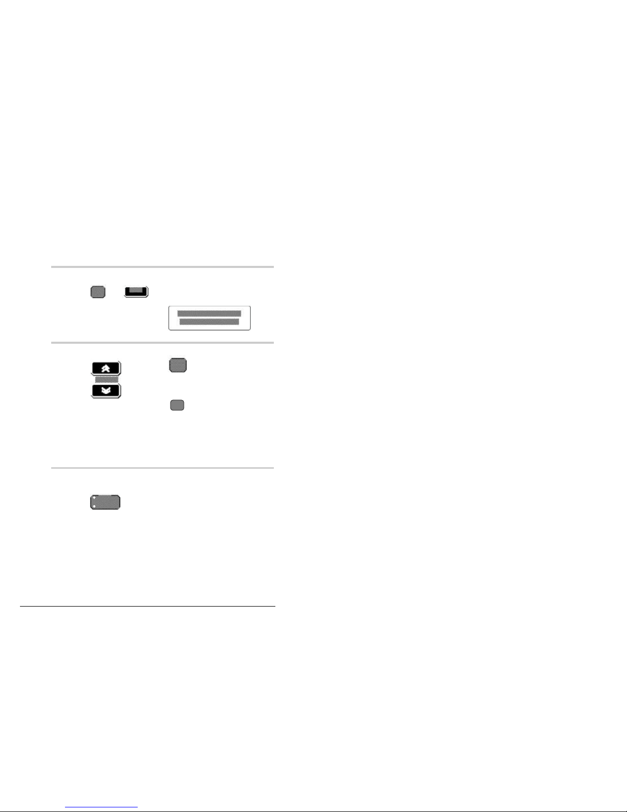
To switch on the console:
Action Notes
1.
To switch on the
power press
The console ‘beeps’ and the
window displays opening messages
(for example, the software version
number).
One of the USB/LSB indicator
lights comes on and the S'call
Mute or Mute light may come on
(depending on the current set up).
If switching on with
a security PIN enter
your PIN number
and press
The display shows:
SECURITY PIN
Ente r _ _ _ _ _ _
2.
The final message on the display is
one of the following:
If the remote transceiver is on:
Cha n
3TxR x
9,983. 0
9,983. 0
Page 25

Using the system
8570 and 8571 Remote control operators handbook 3-3
Action Notes
2. cont.
If the transceiver is off:
In this case follow the instructions
in Switching on the transceiver
from the console, page 3-4.
If the remote power supply is off:
alternating with
In this case you must first switch
the power on at the remote location
and then on at the transceiver.
Page 26

Using the system
3-4 8570 and 8571 Remote control operators handbook
Switching on the transceiver from the console
Refer to the messages in the previous section to decide
whether the transceiver is on or off.
To switch on the transceiver:
Action Notes
1.
Press the green
button on the
console.
For software version V4.00
onwards the display shows:
RADIO
POW ERING UP
Then the display shows the current
transceiver status:
Chan3TxRx9,983.0
9,983.0
The system is ready for use. You must now select a channel
on which to receive or transmit, as explained in the next
section.
q
Page 27

Using the system
8570 and 8571 Remote control operators handbook 3-5
Channels
The transmit/receive channels are stored in the memory of the
transceiver used in the remote control system.
These channels are normally programmed when the
equipment is supplied, but additional channels can be added
by an approved Codan service agent, or where licence
permits, by the operator.
The licensing restriction only applies to transmit frequencies.
Copying channels to another channel location or creating
receive only channels are normally permitted by the user.
For information on copying and creating channels see
Chapter 5, Programming channels.
How to select a channel
To select a channel to send or receive a call, use one of the
following methods:
• Scrolling—use the Channel buttons to scroll through the
channels until you find the one you want. This is the best
method if the channel you want is close to the one
displayed.
• Direct access—select a particular channel using the
Recall button. This is the best method for changing
channels over a large range.
Page 28

Using the system
3-6 8570 and 8571 Remote control operators handbook
Scrolling
Action Notes
1.
Press
up or down until the
channel you want is
displayed.
If you press the button once the
next channel is displayed.
If you hold the button down the
channels are scrolled on the
display.
Page 29

Using the system
8570 and 8571 Remote control operators handbook 3-7
Direct access
Action Notes
1.
Press
(on the numeric
key-pad).
Example of the display:
Re c l
_ ___TxRx
1 2,217.0
1 2,217.0
2.
Enter the channel
number (for a
permanent channel);
or
The channel appears in the lower
left of the display:
Re c l
2 64TxRx
1 2,217.0
1 2,217.0
P-channels P1 to
P99 can be selected
by pressing 0
followed by the
P-channel number
(for systems using
8525/8528 transceivers).
The channel appears in the lower
left of the display:
Re c l
P 85TxRx
11, 5 0 1 . 0
11, 5 0 1 . 0
3.
Press The channel selected is displayed:
Chan
2 64TxRx
1 2,217.0
1 2,217.0
or
Chan
P85TxRx
11, 5 0 1 . 0
11, 5 0 1 . 0
q
Page 30

Using the system
3-8 8570 and 8571 Remote control operators handbook
Tuning the antenna
If you have a manual or automatic antenna tuner, you need to
tune the antenna after selecting a channel if you are about to
transmit a call.
Although the transceiver will tune automatic tuners and
antennas, it is always a good idea to press the Tune button
whenever you change channel. Tuning the antenna makes it
easier to hear when the channel is free from voice and data
traffic before starting a call.
To tune the antenna:
Action Notes
1.
Press The remote antenna starts to tune.
This message displays during the
tuning period:
The transceiver ‘beeps’ while the
antenna is tuning. When it is tuned
two high pitched ‘beeps’ are heard
and this message is displayed:
Page 31

Using the system
8570 and 8571 Remote control operators handbook 3-9
Action Notes
1. cont.
If no tuning point can be found,
two low pitched ‘beeps’ are heard
and this message is displayed:
This means that the antenna may
be faulty or incorrectly installed.
q
Page 32

Using the system
3-10 8570 and 8571 Remote control operators handbook
Adjusting the volume
To adjust the speaker volume:
Action Notes
1.
Press As you adjust the volume, any
muting selected momentarily
switches off.
The transceiver ‘beeps’ at the
minimum and maximum volume
settings.
q
Page 33

Using the system
8570 and 8571 Remote control operators handbook 3-11
Clarifying the signal
Clarifier mode allows you to improve the clarity of the voice
you can hear by adjusting the frequency of your transceiver
channel to match that of the received signal.
To use the clarifier:
Action Notes
1.
Press
(up or down) until
the sound quality is
improved.
The transceiver ‘beeps’ at the
minimum and maximum settings.
q
Page 34

Using the system
3-12 8570 and 8571 Remote control operators handbook
Muting the background noise
Muting allows you to silence the transceiver so that you do
not hear unwanted background noise on the channel until you
receive a call.
Two buttons control the mute setting of the transceiver:
• Mute On/Off—this function inhibits background noise
until a voice signal appears.
• S'call Mute—this function inhibits background noise
until your transceiver has been selectively called. This
function is only available if your transceiver has Selcall
option fitted.
Voice mute
Action Notes
1.
Press
to switch on and off.
The indicator is lit when this
option is selected and the display
does not change.
This control inhibits background
noise until a voice call is received.
Selective call mute
Action Notes
1.
To switch on press
To switch off press
The indicator is lit when this
option is selected and the display
does not change.
This control inhibits background
noise until a selective call is
received.
q
Page 35

Using the system
8570 and 8571 Remote control operators handbook 3-13
Scanning channels
Scanning allows the transceiver to detect incoming calls on
more than one channel frequency. This is useful if you expect
to receive calls from several stations or from stations that
transmit on more than one frequency.
The transceiver scans the list of channels set up in a scan
table. It repeatedly scans each channel in the scan table until
an incoming call is detected on any of the channel
frequencies.
This section gives information on how to select and create a
scan table and how to operate the scanning mode for
incoming calls.
Your system must include a suitable broadband antenna or
Codan automatic antenna tuner for scanning to be successful.
Programming scan tables
The scan tables and programming procedure differ slightly
between the two types of transceivers that can be used with
the remote control system and therefore are detailed
separately:
Transceiver type 8525 and transceiver type 8528 series
With these transceivers you can program up to 15 channels in
sequence for audio (voice) signals. Channels required to
operate on selective call must be programmed within the first
eight channels. There is only one scan table.
When you enter the scan programming mode the
existing scan channels are automatically deleted from
the table.
Page 36
Using the system
3-14 8570 and 8571 Remote control operators handbook
To program scan channels into the transceiver:
Action Notes
1.
Press
then
within one second
to begin the process.
The entries already held in the scan
program are erased.
Example of the display:
2.
Press
up or down to select
the channel to be
used.
Alternatively, press
followed by the channel number
then
Ent er
The channel is shown at the bottom
left. (P57 in the example in step 1.)
Note: to select P channel enter 0
before the channel number.
3.
If necessary, press
the
button to select the
required mode.
The light on the USB/LSB button
shows the current mode.
Page 37

Using the system
8570 and 8571 Remote control operators handbook 3-15
Action Notes
4.
Press
to enter the channel
and mode selection
into the program.
The x1 entry at top right of the
display
indicates the number of times this
channel has been chosen for
scanning. (Note that any selective
calling channels must be within the
first eight entries.)
5.
Press
up or down to select
the next required
channel in the scan
table. Press
to enter. Repeat this
procedure for the
remaining required
channels in the scan
table.
To delete a channel press
on the displayed channel.
Page 38

Using the system
3-16 8570 and 8571 Remote control operators handbook
Action Notes
6.
When you have
entered all the
channels to be
scanned, press
then
within one second
to complete the
process.
The console ‘beeps’ and the
display returns to its previous
status.
If you try to program more than 15
channels, you hear a single lowpitched tone and a warning is
displayed:
7.
If you make an error
while entering the
channels, press
then
then start setting up
the scan table again.
Note: When in scan programming mode press Review to
step through channels in the scan table.
Page 39

Using the system
8570 and 8571 Remote control operators handbook 3-17
Transceiver type 9323 and transceiver type 9360 series
With these transceivers connected into a remote control
system you can program up to eight channels for audio
(voice) or selective call—transceivers not connected in a
remote control system can be programmed for ten channel
scanning.
You can program three separate scan tables.
When you enter scan programming mode you do not delete
existing channels in the table. Any channel not required must
be deleted during scan programming.
Programming the 9323 or 9360 transceiver in the scan mode
will include:
• scan table—1,2 or 3
• scan mode—continuous, audio pause, audio hold, selcall
mute and ALE mute
• channel frequency and operating sideband mode.
To program scan channels into the transceiver:
Action Notes
1.
Press
then
within one second
to begin the process.
The display shows:
ScanPROGRAM
Table number 1
Page 40

Using the system
3-18 8570 and 8571 Remote control operators handbook
Action Notes
2.
Press
up or down to select
the scan table 1, 2
or 3 that you wish to
program.
Alternatively, press 1, 2 or 3 on the
numeric key-pad.
3.
Press
to retrieve the
selected scan table.
The display shows:
Retrieving
Scan table _ _ _
4.
Select scan mode
using
This example shows Selcall mute
selected:
Scan Mode Enter
Selcall m ute
Page 41

Using the system
8570 and 8571 Remote control operators handbook 3-19
Scan mode types available for selection:
Continuous No mute, scan continuous—Scan stops for
Selcall
Audio pause Stops scanning on Voice for three seconds, and
Selcall
Audio hold Stops scanning on Voice for as long as Voice is
present, and Selcall
Selcall mute Stops scanning during selcall
ALE mute Can only be selected if ALE unit is fitted—
Scan stops for ALE calls only.
Note: Current mute setting is also displayed.
Action Notes
5.
Press Your selection will be retained.
Page 42

Using the system
3-20 8570 and 8571 Remote control operators handbook
Action Notes
6.
Press
up or down to select
the channel you
want in the scan
table.
Press
to select Sideband
(if available).
An example of channel display:
Scan PROGRAMMING
6 Rx 12,200.0
7.
Press to
enter the selected
channel into the
scan table.
The display shows:
Scan program x 1
6 Rx 12,200.0
after the channel is programmed
into the scan table.
Page 43

Using the system
8570 and 8571 Remote control operators handbook 3-21
Action Notes
8.
Select remaining
channels required in
the scan table.
Press
to enter each
channel. Press
to delete any
channel from the
table.
9.
Press Use the up and down buttons to
review channels already
programmed into the scan table.
10.
Press
then
within one second
to save your
changes.
To exit without saving changes to
the scan table press PTT.
Page 44

Using the system
3-22 8570 and 8571 Remote control operators handbook
Selecting a programmed scan table
For transceivers 9323 and 9360 it may be necessary to select
a pre-programmed scan table prior to commencement of the
scanning mode for incoming calls. To select the scan table:
Action Notes
1.
Press
followed by
within one second
to select the scan
table.
This example shows table 1
selected:
Sc an P r ogram
Tabl e n u m ber : 1
2.
Press
up or down to select
the required scan
table 1, 2 or 3.
Alternatively, press 1, 2 or 3 on the
numerical key-pad.
3.
Press
to return to channel
mode.
Page 45

Using the system
8570 and 8571 Remote control operators handbook 3-23
Scanning for incoming calls
In scan mode your transceiver is able to listen to selected
channels for Selcall or voice calls. The selected channels are
contained in the scan tables you have created.
Using transceiver 8525 or 8528 series you have only one scan
table: with the 9323 or 9360 you have a choice of three.
Select the required table as detailed in Selecting a
programmed scan table on page 3-22 before commencing
scanning.
The programmed scan facility for 9323 and 9360 provides
five modes of scanning—as for page 3-19—which is
indicated during operation as:
Scan Mode Description Results
Selcall Selcall scanning is the
normal setting if you
expect to receive
Selcalls. Scanning only
stops for Selcalls.
Light on Selcall
button.
Continuous Use Continuous
scanning if you want to
listen to voice traffic as
the channels are
scanned. Scanning only
stops for Selcalls.
No light.
Pause Use Pause scanning if
you expect voice calls
and want scanning to
pause for three seconds
when voice is detected
on the channel.Scanning
also stops for Selcalls.
Light on Mute
On/Off button.
Page 46

Using the system
3-24 8570 and 8571 Remote control operators handbook
Hold Stops when a voice or
Selcall is detected, and
continues only when the
signal stops.
Light flashes on
Mute On'Off
button.
ALE* The scan stops for an
ALE call only.
* only available when an ALE unit is fitted.
Note: On entering the scan mode and the selected table
there may be occasions when only the programmed
channel number is displayed—not the channel
frequency.
If the frequencies are also required to be reviewed it
will be necessary to ‘refresh’ the console’s memory
by recalling the channel number to display the
frequencies before entering the scan mode.
To commence scanning:
Action Notes
1.
Press
to commence
scanning selected
channels.
The scan table number is not
shown for 8525 and 8528. It is
shown for 9323 and 9360:
Chan Scanning 1
10 Rx 5,875.0
Page 47

Using the system
8570 and 8571 Remote control operators handbook 3-25
Action Notes
2.
Press *
for
Selcall mute.
Press *
Mute
On/Off
once for
Pause mute, and
twice for Hold
mute.
* This is for 8525 and 8528 only.
For 9323 and 9360 mute is
programmed in scan mode of the
table.
3.
Press
again to stop scan,
or PTT twice.
If PTT is used the display shows:
P t t n o t
a l l o w e d
It will not transmit.
Page 48

Using the system
3-26 8570 and 8571 Remote control operators handbook
Using autoscan
You can set up your remote control system to scan channels
automatically if no other activity is occurring. (Activity
includes button presses, PTT, commands, or data transfer
mode traffic.)
Using this function, you set a time of 1 to 10 minutes, after
which scanning starts automatically if no system activity
occurs within the time set.
For 9323 and 9360 transceivers only, the autoscan always
selects table 1.
You enable autoscan using a console setup option—function
1. See 8570 and 8571 Remote control installation handbook,
Chapter 6, Setup functions and options for instructions.
q
Page 49

Using the system
8570 and 8571 Remote control operators handbook 3-27
Viewing the setup functions menus
You can view how the console operating function menus and
their options have been installed while in the normal
operating mode.
To view the setup functions:
Action Notes
1.
Press
2.
Enter the relevant
function number
within two seconds
and press Enter.
The display shows
for example.
3.
Press
up or down to scroll
through the menu.
To return to the normal operating display press Function
again (or leave the keys untouched for one minute, after
which time the display resets to normal).
Page 50

Using the system
3-28 8570 and 8571 Remote control operators handbook
Functions and options available
The functions are divided into three groups:
Group 0 console set up—used to set up the console
Group 1 system information—general setup options for the
system as a whole
Group 2 line set up—includes function and option menus
specific to the line or link connecting the system
equipment.
Within each group there are functions that are identified with
a number.
Page 51

Using the system
8570 and 8571 Remote control operators handbook 3-29
See the 8570 and 8571 Installation handbook, Chapter 6,
Setup functions and options for more information about these
functions:
Function Description
Group 0
(Console setup
options)
0
1
2
3
4
5
7
Setting a PIN (password)
General setup options
Access priority options
Set start-up mute
Set display backlight
intensity
Enable/disable monitor
mode
Backup transceiver setup
Group 1
(System
information)
10
11
14
15
18
Transceiver details
Remote control software
details
Local supply voltage
Remote supply voltage
Update channel frequency
memory
Group 2
(Line setup
options)
20
21
25
30
31
35
99
Line parameters
Line equalisation
parameters
Miscellaneous menu
RS-232 terminal menu
Function key setup
RS-232 window
View configuration
q
Page 52

Using the system
3-30 8570 and 8571 Remote control operators handbook
Setting up the console for selective calling
Several parameters must be set before you can use the
selective calling facility. These are:
• your console’s self ID
• called ID (optional)
• call preamble length
• revertive type
• Selcall lockout
• 4-digit or 6-digit compatibility.
Note: You can view these parameters while the console is
in the normal operating mode (see Viewing the setup
functions menus on page 3-27), but the console must
be in setup mode before you can set or change them.
Setup mode—selective call
It is assumed that the general setup procedure for selective
call operation has been done during the system installation.
However, there will be a requirement by the system operator
to change some of the setup parameters from time to time. For
this purpose the following has been reprinted from the
installation handbook.
To enter setup mode, turn the console off. Then, press and
hold down the Function and Control On/Off buttons
together for about two seconds to turn the console back on.
‘Setup Mode’ will be displayed. If your console has a PIN
number, after the Function and Control On/Off keys are
held down the display will show ‘SECURITY PIN’. Enter
the PIN number and press Enter.
See also the 8570 and 8571 Remote control installation
handbook, Chapter 6, Setup functions and options:
Function 1.
Page 53

Using the system
8570 and 8571 Remote control operators handbook 3-31
Making changes—selective call
To install or change the selective call operating parameters,
enter the setup function 1 once the setup mode has been
selected (see Viewing the setup functions menus on page
3-27). Then:
Action Notes
1.
Press
then
then
Press the 1 within two seconds.
The display shows:
The display shows:
2.
Press
up or down to view
the menu options.
Press
up or down to
change the state of
any option.
You do not need to press Enter to
save any option. If it is displayed
when you press the Review button
to move to the next option, it will
be saved when you leave the
General Setup menu.
To leave the setup mode, switch
the console off using the On/Off
key.
Page 54

Using the system
3-32 8570 and 8571 Remote control operators handbook
The following setup options are to be reviewed.
Selective call self-identification
This function sets your console’s address for selective calling.
The console only responds to selective calls made to this
address. Use the numeric key-pad to enter the address:
• maximum of 4 digits for 8525/8528 transceivers
• maximum of 6 digits for 9323/9360 transceivers.
Note: Do not use an address ending in 00 or 99. These
numbers are reserved for State, All calls and 99
beacon calls.
For split site systems all connected transceivers (operating
receivers and transmitters) must not be programmed with a
Selcall self address ID. See the 8570 and 8571 Installation
handbook, Chapter 2, Overview, Selective calling for more
information.
Example of the display:
Refer to Making changes—selective call on page 3-31 for the
procedure for making changes.
Selective call called address
This option sets an address to be called automatically each
time you press the Call key. If you do not set an address you
can enter any address when you press Call:
• maximum of 4 digits for 8525/8528 transceivers
• maximum of 6 digits for 9323/9360 transceivers.
Example of the display:
Refer to Making changes—selective call on page 3-31 for the
procedure for making changes.
Page 55

Using the system
8570 and 8571 Remote control operators handbook 3-33
S’call preamble length
This function sets the preamble length. There are two options:
• ‘short’—two seconds
• ‘long’—six seconds.
You must use a long preamble if you are calling a scanning
station. This is applicable for type 8525/8528 series
transceiver.
For transceiver type 9323/9360 the preamble length is setup
in the transceiver when ALE scan is selected.
Example of the display:
Refer to Making changes—selective call on page 3-31 for the
procedure for making changes.
Selective call revertive type
This function sets the type of selective call revertive sent to a
calling station. The revertive can be either:
• ‘tone’—the standard revertive type
• ‘digi’—digital—only used under special circumstances
Tone setting is the normal operating mode.
Example of the display:
GENE RA L SETUP
Rev erti v e: ton e
Refer to Making changes—selective call on page 3-31 for the
procedure for making changes.
Page 56

Using the system
3-34 8570 and 8571 Remote control operators handbook
Selcall lockout
This function switches Selcall lockout on or off. Switching on
Selcall lockout prevents you from sending a Selcall or beacon
call if the transceiver detects that another station is sending a
call on the same channel. This reduces call interference
between stations and increases the chance of success when a
Selcall or beacon call is transmitted.
The options are:
• ‘on’
• ‘off’.
Example of the display:
GENERAL SETUP
S'call Lock: off
Refer to Making changes—selective call on page 3-31 for the
procedure for making changes.
Page 57

Using the system
8570 and 8571 Remote control operators handbook 3-35
Digits—4 or 6 digit compatibility
This function allows communication with stations whose
address is either 4 or 6 digits.
The options are:
• ‘4 or 6’—to allow 4-digit and 6-digit addresses
• ‘6 only’—to allow 6-digit addresses only.
Example of the display:
GENERAL SETUP
Digits : 4 or 6
Refer to Making changes—selective call on page 3-31 for the
procedure for making changes.
q
Page 58

Using the system
3-36 8570 and 8571 Remote control operators handbook
Page 59

8570 and 8571 Remote control operators handbook 4-1
4 Sending and receiving calls
This chapter explains how to send and receive calls. It
assumes that the equipment has been installed and setup to
operate correctly, as described in the 8570 and 8571 Remote
control installation handbook, Chapter 3, Installation.
This chapter covers:
• Sending a voice call (4-2)
• Selective calling (4-5)
• Group calls (4-14)
• State calls and All calls (4-15)
• Using the beacon feature (4-17)
• Sending and receiving tone calls (4-23)
• Using the free-tuning receiver (4-28)
• Using the console as an intercom (4-30)
• Receiving emergency Selcalls (4-36).
Throughout this section all displays show examples of
channel and frequency numbers. You must insert your
selected channel and frequency numbers as appropriate.
q
Page 60

Sending and receiving calls
4-2 8570 and 8571 Remote control operators handbook
Sending a voice call
To send a voice message, select the correct channel and
adjust the volume. If you have an automatic tuning system,
tune the antenna before you start transmitting.
To send a voice call:
Action Notes
1.
Listen: Make sure the selected channel is
free of traffic before you begin
your transmission.
2.
Press the
microphone PTT
button.
Hold the microphone side-on, close
to your mouth, and
speak clearly.
A vertical bar graph replaces ‘Tx’
in the display to indicate that
transmission is occurring:
Note: Remember to release the
PTT button to listen for a
response.
Page 61

Sending and receiving calls
8570 and 8571 Remote control operators handbook 4-3
Action Notes
3.
If you hear two low pitched tones
and this error message appears on
the display:
,
you have an automatic antenna
tuning system that has not been
tuned.
Refer to Chapter 3, Using the
system, Tuning the antenna for
instructions.
Using the microphone
When talking into the microphone:
• hold the microphone side-on and close to your mouth.
• press and hold down the PTT button
• speak clearly at normal volume and rate
• use the word ‘over’ to indicate when you have finished
speaking and release the PTT button
• your conversation can be monitored by anyone tuned to
your transmit frequency.
Page 62

Sending and receiving calls
4-4 8570 and 8571 Remote control operators handbook
PTT timer
The PTT transmit cutout sets a timer to prevent the
transceiver being left on in the transmit state by mistake.
The timer is set in the factory to ten minutes, but you can
adjust this if you wish.
You set the PTT timer using a general setup option—function
1. See 8570 and 8571 Remote control installation handbook,
Chapter 6, Setup functions and options for instructions.
q
Page 63

Sending and receiving calls
8570 and 8571 Remote control operators handbook 4-5
Selective calling
Selective call allows you to call an individual transceiver or a
group of transceivers. This can be likened to a normal
telephone system where the called station has a unique calling
address or number.
Selective call also allows you to call a group of stations.
Each transceiver and console in the system has its own
identification number. The identification number is a four or
six digit code that is either:
• programmed into the transceiver using the front panel
buttons
• pre-set at the factory.
The selective call feature operates by the transmission and
reception of coded signals. These signals contain the
identification number of the station being called (the called
address) and the number of the station sending the call (the
self-identification).
The identification numbers are represented by 4-digit codes
for 8525/8528 transceivers and 4- digit or 6-digit codes for
9323/9360 transceivers. You program these codes into the
memory using the console’s key-pad.
Setting up the transceiver and console
It is assumed that all system transceivers installed incorporate
the selective call facility and that for split site operation the
transceivers do not have the self ident address programmed.
Your console must be set up to use the selective calling
facility. For information about how to do this, see Chapter 3,
Using the system, Setting up the console for selective calling.
Page 64

Sending and receiving calls
4-6 8570 and 8571 Remote control operators handbook
Sending a selective call
From channel mode:
Action Notes
1.
Press
up to down to select
the required
channel.
The display shows:
Chan 2TxRx2,500.0
2,500.0
2.
Turn the mute off
using
You will hear background receiver
noise.
3.
If your system has
an automatic
antenna tuner
system, press
to tune this channel.
Receiver noise may increase.
4.
Listen. Ensure the selected channel is free
of voice or data transmission.
Page 65

Sending and receiving calls
8570 and 8571 Remote control operators handbook 4-7
Action Notes
5.
Press The display shows:
Chan 2Sen d be ac on
to 12 34 56
6.
If Call (Selcall) is
not displayed press
up or down until
Call is shown, or
press
The display shows:
Chan 2Sen d ca ll
to 12 34 56
7.
Press numerals
0 9TO
to enter the Selcall
ID (if different from
that displayed).
The display shows:
Chan 2Sen d ca ll
to 23 22 46
If fixed in the setup menu the ID
cannot be changed.
8.
Press
to send call.
The display shows:
Cha n
2
Sen din g
23224 6
You will hear a ‘warbling’ sound
for approximately ten seconds.
Page 66

Sending and receiving calls
4-8 8570 and 8571 Remote control operators handbook
Action Notes
9.
Listen. If the Selcall is successful a
revertive of six ‘beeps’ will be
heard from the called station.
If the called station is attended,
voice communication can
commence.
If unattended, your call will be
recorded in the call stack at the
called station for later
communications.
Page 67

Sending and receiving calls
8570 and 8571 Remote control operators handbook 4-9
Receiving a selective call
When you receive a selective call, you will hear a series of
three telephone rings or 16 short ‘beeps’ for group calls.
If the transceiver is unattended the call is stored in the call
stack. It is also shown on the channel display as shown:
Cha n
11
Tx
25268
3,80 0.0
Cald
The caller’s self ID and ‘Cald’ is displayed on the receive
channel.
Cald Sca nning
2 2,500.0
An example as seen on other scanning channels.
If you do not answer the call immediately, after the call is
stored in the call stack the console will continue to sound a
beep every four seconds to indicate a call has been received.
Any function on the control panel will silence the beeps, eg.
Volume or .
To answer the call and begin normal two-way conversation,
stop Scanning by pressing Scan, and select the called
channel. Press the PTT button and begin to speak into the
microphone.
Note: Pressing PTT on the called channel removes the
‘Cald’ and ID from the display. The called ID
remains in the call stack.
Pressing Delete will delete entries from the call
stack when you are reviewing calls.
Page 68

Sending and receiving calls
4-10 8570 and 8571 Remote control operators handbook
Receiving a selective call in scan mode
When a Selcall signal is received during selective call
scanning, scanning is stopped until the call is decoded. If the
call is found to be addressed to the console, three telephone
rings are heard and the scanning is halted. The display shows
the number of the channel on which the call was received.
After the telephone rings a single ‘pip’ is sounded at four
second intervals. When scanning is resumed, the ‘pips’
continue and the display shows the address of the calling
station on the channel(s) on which the calls were received.,
For example, when a station with Selcall ID 555661 calls on
the channel 1234 whilst in scan table 1, the display shows:
Chan
1 234
Sc a nni n g
5 55 661
1
Cald
The call is stored in the call stack memory. The call stack can
record up to 20 calls and can be reviewed at any time (see
Reviewing received calls on page 4-11). The ‘pips’ can be
stopped by operating any button function. See also Receiving
a selective call on page 4-9.
See Chapter 3, Programming scan tables for instructions for
programming the channels.
Page 69

Sending and receiving calls
8570 and 8571 Remote control operators handbook 4-11
Reviewing received calls
The console records up to 20 separate calls in its memory. If a
station calls more than once on the same channel, it is only
recorded once.
If more than 20 calls are received, the first call stored in the
stack is deleted to make room for the latest call. When power
is removed from the console all information in the call stack
is lost.
To view the stack, press one of the Review buttons. If no
calls have been received, the display shows:
If one or more calls have been received, the display shows:
C h a n r e v i e w 1
3 2 4 3 4 2 2 c a ll e d
The display shows the caller’s selective call ID and the
channel number called. The last station to call is shown first.
For tone calls received and held in memory (8525and 8528
systems) the display shows:
C h a n r e v i e w 1
3 2 4 To n e c a l l
To review the calls, press the Review buttons. Each entry
includes the channel on which the call was received.
Page 70

Sending and receiving calls
4-12 8570 and 8571 Remote control operators handbook
Returning a Selcall from the call stack:
Action Notes
1.
Press
to select the call you
wish to send.
The display shows:
C h a n r e v i e w 1
3 2 4 3 4 2 2 c a ll e d
2.
Press twice This will send a Selcall to the
station that called you using the
same channel and call ID.
Page 71

Sending and receiving calls
8570 and 8571 Remote control operators handbook 4-13
Returning a tone call—8525/8528 series—from the call stack:
Action Notes
1.
Press
to select the call to
be returned.
The display shows:
C h a n r e v i e w 1
3 2 4 To n e c a l l
2.
Press once
q
Page 72

Sending and receiving calls
4-14 8570 and 8571 Remote control operators handbook
Group calls
A group call is a special type of selective call in which a
coded message is transmitted to all stations in a selected
group.
Note: You can still call an individual station in that group
by entering the station’s ID in the console in the
normal way.
Sending a group call
You send a group call in the same way as any other selective
call—by pressing the Call button—but for a group call the
address must end in 00.
For example, a call to station 0200 is received by all stations
whose identification address is in the range from 0201 to
0299.
No revertive will be heard.
q
Page 73

Sending and receiving calls
8570 and 8571 Remote control operators handbook 4-15
State calls and All calls
State calls and All calls are both variations on the standard
group call. They are used only for special case applications
with engineered systems incorporating custom built
transceivers programmed to operate within this calling mode.
State calls
A State call is a message transmitted to all stations with the
same first digit for a 4-digit Selcall and the same three digits
for a 6-digit Selcall. For example, if your console has the selfidentification number beginning with 234 for a 6-digit Selcall,
a State call will call all stations from 234001 to 234998. At
each receiving console an alarm of 16 short beeps sounds
when the State call is received. No revertive signal is sent.
All calls
An All call is a message transmitted to all stations on a given
channel capable of responding to a selective call (stations
0000 to 9999). At these stations an alarm of 16 short beeps
sounds. No revertive signal is sent. All calls are used almost
exclusively for emergencies.
Each transceiver must be programmed to respond to either a
State call or an All call. A special functions menu (function 2)
is used to select the option at the console. See 8570 and 8571
Remote control installation handbook, Chapter 6, Setup
functions and options for instructions.
Page 74

Sending and receiving calls
4-16 8570 and 8571 Remote control operators handbook
To send a State call or an All call:
Action Notes
1.
Press
and use
to select State or
All.
The display shows:
2.
Press
to send the State or
All call.
The display shows:
C h an S endin g
2 8 t o A L L
The type of call sent depends on how your software is set and
is indicated on the display when you send the call.
q
Page 75

Sending and receiving calls
8570 and 8571 Remote control operators handbook 4-17
Using the beacon feature
The beacon facility is used to check signal conditions
between two transceivers fitted with selective call.
The beacon facility has two modes of operation:
• selective beacon mode
• base station (99) beacon mode.
A beacon signal consists of four long tones. Selfidentification addresses ending in 99 should be avoided.
No alarm or call is recorded at the remote receiving
transceiver or local console. A revertive transmission from
the transceiver is not indicated by the console.
If the receiving transceiver (console) is in scan mode,
scanning starts again immediately.
Normal selective operation is not affected.
Note: If you have an 8525/8528 transceiver with software
earlier than version 3.50, you have to send a
99-beacon call. See Sending a 99-beacon call on
page 21.
Page 76

Sending and receiving calls
4-18 8570 and 8571 Remote control operators handbook
Sending a selective beacon call
You usually send several selective beacon calls before
deciding which channel to use for sending a Selcall.
When you send a selective beacon call, the receiving station
acknowledges your call by sending a beacon revertive signal
consisting of four long beep tones. You compare the quality
of the revertive signals to decide which is the best channel to
use for communication.
Selective beacon calls allow you to check channel conditions
without disturbing stations in your network by frequent test
calls. A transceiver receiving a selective beacon call does not
record the call or alert the operator.
Before you can make a selective beacon call you need to
ensure that the following has been set up:
• your self ID
• a channel for Selcalling
To send a selective beacon call:
Action Notes
1.
If in scan mode
press
or PTT to stop
scanning.
The display shows:
Cha n
11TxR x
3,80 0.0
3,80 0.0
2.
Press The display shows:
Cha n
11
S endto ca l l
122 563
Page 77

Sending and receiving calls
8570 and 8571 Remote control operators handbook 4-19
Action Notes
3.
Press
up or down or
to display beacon.
The display shows:
Chan Send beacon
11 t o 12256 3
4.
Enter the Selcall
address using the
numeric buttons
0 9TO
(if it is different
from that displayed
or fixed in the Setup
menu).
The display shows:
Cha n
11
S endto b e a con
144 466
5.
Press
to send beacon.
The display shows:
Cha n
11 t o
B e a c o n i n g
1 4 4 4 6 6
6.
Listen for the
revertive of four
long tones.
If the receiving station has an
automatic antenna tuning system it
will tune the antenna before
transmitting the revertive.
Page 78

Sending and receiving calls
4-20 8570 and 8571 Remote control operators handbook
Action Notes
7.
The transceiver returns to channel
mode after the selective beacon
call has been completed.
Chan11TxRx3,800.0
3,800.0
Page 79

Sending and receiving calls
8570 and 8571 Remote control operators handbook 4-21
Sending a 99-beacon call
If your system consists of an 8525/8528 transceiver and the
software is earlier than 3.50 you must send a beacon call to a
station address ending in 99.
This type of beacon call is used to call older transceivers that
are incapable of responding to selective beacon calls.
With a base station enabled for beacon mode, it will transmit
a beacon signal on receipt of a selective call ending in 99.
The thousand and hundred digits of the address must be the
same for both the beacon transmitting and receiving stations.
If mobile transceivers have the beacon enabled, the first two
digits of each mobile transceiver’s self-identification address
should be set to a different number so that they do not all
transmit a beacon response together.
Before you can make a 99-beacon call, ensure the following
has been set up:
• the station you are calling is set up for 99-beacon calls
• your self-ID (refer to the 8570 and 8571 remote control
installation handbook, Chapter 6, Setup functions and
options: Function 1)
• a channel for Selcalling.
Page 80

Sending and receiving calls
4-22 8570 and 8571 Remote control operators handbook
To make a 99-beacon call:
Action Notes
1.
In channel mode
select a transmit
channel that is
scanned by the
station being called.
2.
Press
3.
Then enter the
station address
using the numeric
buttons with 99 as
the last two digits
0 9TO
The display shows:
Ch a n B e acon
28 t o 35 9 9
4.
Press
again to send the
call.
q
Page 81

Sending and receiving calls
8570 and 8571 Remote control operators handbook 4-23
Sending and receiving tone calls
A tone call allows you to call a station that has been setup and
is capable of receiving your two-tone calling signal.
This section covers sending a tone call for 9323/9360
transceivers and both sending and receiving a tone call for
8525/8528 transceivers.
Selective calling has largely replaced tone calling as a method
of calling specific stations. You may want to use tone calling
if some stations in your network are incapable of using Selcall
ID’s.
Note: Tone decoding is only available with transceivers
8525/8528 fitted with option TD.
For 8525/8528 series transceivers option TE is
required for sending tone calls: option TD is
required for receiving tone calls. You cannot use
these options and selective calling on the same
channel. The calling party is not identified.
The TE option only operates on channels
programmed with either T1, T2, T3 or T4.
See Chapter 5, Programming Channels for instructions.
Page 82

Sending and receiving calls
4-24 8570 and 8571 Remote control operators handbook
Sending a tone call
To send a tone call for 9323/9360 transceivers:
Action Notes
1.
If in scan mode
press
or PTT to stop
scanning.
The display shows:
Cha n
11TxR x
3,80 0.0
3,80 0.0
2.
Press
up or down to select
the required channel
with tone call
enabled.
The display shows:
Chan18TxRx5,880.0
5,880.0
3.
Press The display shows:
Chan
1 8
Sen dTo ca l l
5,88 0.0
Page 83

Sending and receiving calls
8570 and 8571 Remote control operators handbook 4-25
Action Notes
4.
Press
up or down until
Tone 1,2,3 or 4 is
displayed, or press
The display shows:
Chan18Sen d
Tone c a ll 1
5.
Press
and hold for
approximately 10
seconds.
The display shows
Chan18Se n din g
Tone c a ll 1
and a tone is heard during the
transmission.
Page 84

Sending and receiving calls
4-26 8570 and 8571 Remote control operators handbook
To send a tone call for 8525/8528 transceivers:
Action Notes
1.
If in scan mode
press
or PTT to stop
scanning.
The display shows:
Cha n
11TxR x
3,80 0.0
3,80 0.0
2.
Press
up or down to select
the required channel
with tone call
enabled.
The display shows:
Chan18TxRx5,880.0
5,880.0
3.
Press
and hold for
approximately 10
seconds.
The display shows:
Chan Sending
18 Tone call
and a tone is heard during the
transmission.
Page 85

Sending and receiving calls
8570 and 8571 Remote control operators handbook 4-27
Receiving a tone call—8525/8528 series
If your transceiver is an 8525/8528 and has Option TD fitted,
when a call is received, the console emits three short ‘pips’
and the display shows, as an example:
Chan
18TxTone
5,880.0
call
After the initial alarm, the pips are repeated at four second
intervals.
To cancel the pips and answer the call, press the microphone's
PTT button.
The tone call appears in the call memory stack. You can
review it or delete the call, following the procedure in
Reviewing received calls on page 4–11.
q
Page 86

Sending and receiving calls
4-28 8570 and 8571 Remote control operators handbook
Using the free-tuning receiver
The console can be used to operate Codan transceivers as
free-tuning receivers. You can then receive signals or
broadcasts within the frequency range of 250 KHz to 30
MHz. The channel created is temporary and is lost when you
change channels or turn off the console. Transmission is
inhibited to prevent you inadvertently transmitting on a
broadcast or other receive-only frequency.
To use the transceiver as a free-tuning receiver, make sure the
console is turned on and any channel is selected, then proceed
with one of the following methods.
First method: to select a fixed frequency:
Action Notes
1.
Enter the first digit
of the frequency
you want.
The display changes from the
original selection to show:
2.
Enter the numbers
for the remainder of
the frequency.
The numbers will appear on the
display as you enter them.
3.
Press The display shows the selected
frequency:
This procedure sets up a temporary channel at your chosen
frequency. To return to the original channel selection press
Channel up or down.
Page 87

Sending and receiving calls
8570 and 8571 Remote control operators handbook 4-29
Second method: to scan through the frequencies starting with
the entered frequency:
Action Notes
1.
Press
and hold.
The display changes from the
original selection to show the Rx
frequency only:
Entr
5TxR x
_ _ _ _
17, 5 35.0
2.
Then press
or
The displayed frequency can be
changed up or down in steps of
0.1 kHz with a single press of the
buttons or continuous scan from
the original frequency. The display
shows:
Entr
Tu n e Rx 17,5 35 . 0
3.
Release
when you end free
tuning.
The display will remain at the
frequency shown when Enter was
released.
To return to the original channel selection press Channel up
or down.
q
Page 88

Sending and receiving calls
4-30 8570 and 8571 Remote control operators handbook
Using the console as an intercom—basic single
site, split site or daisy chain
If your system includes more than one console, you can use
each as an intercom to call any or all of the others. Each
console is allocated an intercom number during installation
(for more information refer to the 8570 and 8571 Remote
control installation handbook, Chapter 6, Setup functions
and options, General setup options—function 1). You can
call an individual console by ‘dialling’ its number. The
intercom system uses a party line that does not exclude other
consoles.
When Intercom is pressed to enter the intercom mode, all
transceiver operations are suspended and all consoles in the
system will have ‘intercom’ displayed. If no buttons are
touched for one minute, the system returns to normal
transceiver operation.
If a console is in use in a system all others will display
‘Busy’.
Each console should be setup with the intercom identity
number and the intercom answer mode using:
• ‘auto’—to give two rings before the console is connected
• ‘normal’—to give eight rings with the console only being
connected if PTT is pressed.
Page 89

Sending and receiving calls
8570 and 8571 Remote control operators handbook 4-31
Example—operator 1 calling operator 2
This example shows you (operator 1) how to use the intercom
to call a single operator (operator 2):
Action: Operator 1's display shows: Operator 2's display shows:
Press
followed by: followed by:
Press
Press
Press
The console beeps.
Page 90

Sending and receiving calls
4-32 8570 and 8571 Remote control operators handbook
Action: Operator 1's display shows: Operator 2's display shows:
If operator 2 is not present or the
console is not turned on, the
message is:
If connection is made the
message is:
The console emits a series of
beeps.
The console emits a series of
beeps.
If connection
is made,
press PTT
and speak.
To end,
press:
Display returns to normal
transceiver mode.
Display returns to normal
transceiver mode.
Page 91

Sending and receiving calls
8570 and 8571 Remote control operators handbook 4-33
Example—operator 1 calling all operators
This example shows you (operator 1) how to use the intercom
to call all other consoles in your system:
Action: Operator 1's display shows: Other operator (example
shown is 2) displays show:
Press
followed by: followed by:
Press
Press
Press
The console beeps.
Page 92

Sending and receiving calls
4-34 8570 and 8571 Remote control operators handbook
Action: Operator 1's display shows: Other operator (example
shown is 2) displays show:
The console emits a series of
beeps.
If connection
is made,
press PTT
and speak.
This procedure sets up a party line in which any operator can
take part. While you are talking, a message to this effect is
displayed. All other consoles display a message identifying
the number of the operator who is talking. If you try to talk
while another operator is talking, the following message is
displayed:
Page 93

Sending and receiving calls
8570 and 8571 Remote control operators handbook 4-35
Several options are available to you while you are using the
intercom:
To do this: Press these buttons: Your display shows:
Leave the party line
Force all operators to
leave intercom mode
Normal transceiver operation
messages.
Re-enter a party line The same series of connection
messages are displayed as when
starting the party line.
or
This enters the party line but
does not inform the other
consoles.
q
Page 94

Sending and receiving calls
4-36 8570 and 8571 Remote control operators handbook
Receiving emergency Selcalls
If your system includes transceivers 9323/9360 with
emergency Selcall option enabled or transceivers 8525/8528
with software version 3.52 or later, the console can receive,
emergency Selcalls. It cannot send emergency Selcalls.
When an emergency call is received an alarm sounds to alert
the operator. If the external alarm is installed (see the 8570
and 8571 Remote control installation handbook, Chapter 3,
Installation, External alarm) the alarm relay will pulsate
when an emergency call is received, instead of remaining
permanently on as is the case for normal Selcalls. A
successfully received call will initiate a revertive signal being
returned to the caller: this activates a two tone (‘siren’) alarm
at the caller’s console.
It is assumed that during installation the Emergency mode of
function 1 (see the 8570 and 8571 Remote control
installation handbook, Chapter 6, Setup functions and
options) has been selected to receive Emergency Selcalls
and—as necessary—the two emergency only ID’s have been
programmed.
Ensure the emergency ID addresses are not the same as the
console self ID addresses.
q
Page 95

8570 and 8571 Remote control operators handbook 5-1
5 Programming channels
This chapter explains how to program channels in your remote
control system. It assumes that the equipment has been installed
and setup to operate correctly, as described in the 8570 and 8571
Remote control installation handbook, Chapter 3, Installation.
This chapter covers:
• Programming transceivers type 8525 and 8528 (5-2)
• Programming transceivers type 9323 and 9360 (5-16).
Throughout this section all displays show examples of
channel and frequency numbers. You must insert your
selected channel and frequency numbers as appropriate.
Generally transceivers are supplied with an inbuilt facility
(option TXD—Transmit Disabled) which prevents you from
programming or changing transmit frequencies from the
control panel. Under special circumstances, and where local
licensing authorities permit, option TXE (transmit enabled)
may be fitted to the transceiver which allows you to create or
change the transmit frequencies of your transceiver.
Channels programmed by Codan or by an approved service
agent are stored in the internal memory of the transceiver.
These can be reprogrammed or deleted by Codan or the
service agent.
You can copy existing transmit/receive frequencies to another
location which allows you to group a number of channels
together. You can also create new receive-only channels for
broadcast reception or monitoring.
The two transceivers series 8525/8528 and 9323/9360 that
can be used with the system differ slightly in their programming and have therefore been detailed separately as follows.
Page 96

Programming channels
5-2 8570 and 8571 Remote control operators handbook
Programming transceivers type 8525 and 8528
In the 8525 and 8528 there are 99 programmable channels
(P-channels) that can be programmed by you and numbered
P01 to P99. Existing channels may be copied as P-channels
and their option modified, such as :
• S-selective call
• t-calls (four 2-tone calls)
• Upper Sideband mode (USB) or Lower Sideband mode
(LSB)
Note: If you are using and intend programming an 8525B
transceiver, you will need to fit a link (3) on the
microprocessor PCB (08-03741) of the transceiver
before you can program, replace, or delete P-channels.
This is an installation operation: refer to the technical
service manual 15-02036 for details.
Page 97
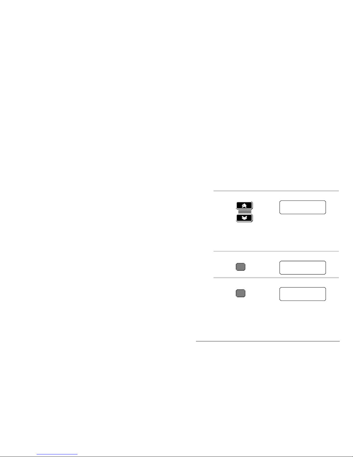
Programming channels
8570 and 8571 Remote control operators handbook 5-3
Copying channels to a P-channel—8525 and 8528
A receive/transmit P-channel allows you to receive and
transmit on the same frequency.
You can copy an existing channel, creating a new P-channel
using the same Tx and Rx frequencies. You might do this, for
example, if you want two different configurations for the
same frequency. To copy a channel:
Action Notes
1.
Press
up or down to select
the channel with the
required Tx and Rx
frequencies.
The display shows:
Chan
264TxRx
12,217.0
12,217.0
2.
Press The display shows:
Entr
264TxRx
__,___,_
12,217.0
3.
Press
to display the option
fields.
The display shows:
Entr
264
opt ion s
S_,_U
Page 98

Programming channels
5-4 8570 and 8571 Remote control operators handbook
Action Notes
4.
Press
and select one of the
options S/T1/T2/T3
and T4.
The display shows:
Entr
264
opt ion s
T1,_U
5.
Press
to select one of the
options U (USB), L
(LSB), or LU
(both).
The display shows:
Entr
264
opt ion s
T1,LU
Note: Special hardware is
required for operation in
lower sideband—option L.
6.
Press
to confirm your
selections when the
correct options are
displayed.
The display shows:
Entr
P__TxRx
12,21 7 . 0
12,21 7 . 0
7.
Enter the channel
number.
The display shows:
E ntr
P 85TxRx
1 2,217.0
1 2,217.0
Page 99

Programming channels
8570 and 8571 Remote control operators handbook 5-5
Action Notes
8.
If the channel
number is already
programmed, the
console ‘beeps’ and
displays a warning
message. To
continue, enter
another channel to
be used.
The warning message shows:
The channel selection screen is
displayed again with the channel
number you entered flashing.
Do not press Enter before you enter a new channel
number. If you do, the channel will be overwritten.
9.
Press
to confirm
the channel
selection.
The console ‘beeps’ to indicate
completion and the display remains
unchanged.
The new channel is now ready for use. It remains selected
until you change it by pressing one of the Channel buttons.
Note: Two-frequency simplex channels (those in which the
Rx and Tx frequencies are different) must only use
channel reference P70 to P99.
Page 100

Programming channels
5-6 8570 and 8571 Remote control operators handbook
Creating a receive-only P-channel—8525 and 8528
A receive-only channel is one in which transmission is not
allowed and has been inhibited. This is useful, for example,
for setting up channels to receive broadcasts on frequencies
where it is illegal to transmit.
To create a receive only channel:
Action Notes
1.
Press
up or down to select
any channel.
The channel frequency is
displayed, as shown in the
example:
Chan
264
12,217,0
12,217,0
Tx
Rx
2.
Press The display shows:
Entr
264
__,___,_
12,217,0
Tx
Rx
3.
Press
to begin to program
the channel.
The display shows:
Entr
264
inhib i t
__,___,_
Tx
Rx
 Loading...