

Page 1

Block Up Converter Systems
6700/6900 series
SATELLITE COMMUNICATIONS
USER GUIDE
Page 2

No part of this guide may be reproduced, transcribed or
translated into any language or transmitted in any form
whatsoever without the prior written consent of Codan
Limited.
© Copyright 2006 Codan Limited.
Codan part number 15-44027-EN Issue 1, October 2006
Page 3

Table of contents
Introduction
1Overview
Introduction. . . . . . . . . . . . . . . . . . . . . . . . . . . . . . . . . . . . . . . . . . . . . . . . . . 4
BUC system configuration . . . . . . . . . . . . . . . . . . . . . . . . . . . . . . . . . . . . . . 5
BUC . . . . . . . . . . . . . . . . . . . . . . . . . . . . . . . . . . . . . . . . . . . . . . . . . . . . . . . 7
Transmit frequency bands . . . . . . . . . . . . . . . . . . . . . . . . . . . . . . . . . . . . 7
Frequency conversion plans . . . . . . . . . . . . . . . . . . . . . . . . . . . . . . . . . . 7
Power supply options . . . . . . . . . . . . . . . . . . . . . . . . . . . . . . . . . . . . . . 13
LNB . . . . . . . . . . . . . . . . . . . . . . . . . . . . . . . . . . . . . . . . . . . . . . . . . . . . . . 15
Redundancy systems. . . . . . . . . . . . . . . . . . . . . . . . . . . . . . . . . . . . . . . . . . 16
The redundancy controller . . . . . . . . . . . . . . . . . . . . . . . . . . . . . . . . . . 17
How the redundancy controller works . . . . . . . . . . . . . . . . . . . . . . . . . 20
RF waveguide switches. . . . . . . . . . . . . . . . . . . . . . . . . . . . . . . . . . . . . 23
The Remote Controller 6570 and Hand-held Controller 6560 . . . . . . . . . . 26
2 Installation
CODAN
Unpacking the equipment . . . . . . . . . . . . . . . . . . . . . . . . . . . . . . . . . . . . . . 28
Installing the BUC equipment . . . . . . . . . . . . . . . . . . . . . . . . . . . . . . . . . . 28
Cable recommendations . . . . . . . . . . . . . . . . . . . . . . . . . . . . . . . . . . . . . . . 32
Cable lengths. . . . . . . . . . . . . . . . . . . . . . . . . . . . . . . . . . . . . . . . . . . . . 33
IF levels. . . . . . . . . . . . . . . . . . . . . . . . . . . . . . . . . . . . . . . . . . . . . . . . . 34
Serial interfaces. . . . . . . . . . . . . . . . . . . . . . . . . . . . . . . . . . . . . . . . . . . . . . 37
RS232 interface. . . . . . . . . . . . . . . . . . . . . . . . . . . . . . . . . . . . . . . . . . . 37
RS422/485 interface . . . . . . . . . . . . . . . . . . . . . . . . . . . . . . . . . . . . . . . 38
FSK interface . . . . . . . . . . . . . . . . . . . . . . . . . . . . . . . . . . . . . . . . . . . . 38
Connecting the serial interface . . . . . . . . . . . . . . . . . . . . . . . . . . . . . . . . . . 39
Permanent interface connection . . . . . . . . . . . . . . . . . . . . . . . . . . . . . . 39
Temporary interface connection . . . . . . . . . . . . . . . . . . . . . . . . . . . . . . 39
Monitor and control interface of the BUC . . . . . . . . . . . . . . . . . . . . . . . . . 40
Installing the redundancy system . . . . . . . . . . . . . . . . . . . . . . . . . . . . . . . . 42
Block Up Converter Systems 6700/6900 series User Guide i
Page 4

Table of contents
Mounting the redundancy controller . . . . . . . . . . . . . . . . . . . . . . . . . . . 42
Installing separate transmit and receive RF waveguide switches . . . . . 42
Installing the combined RF waveguide/coaxial switch (C-Band
transmit/receive systems only). . . . . . . . . . . . . . . . . . . . . . . . . . . . . . . .45
Connecting the power cables . . . . . . . . . . . . . . . . . . . . . . . . . . . . . . . . . 47
Connecting the control cables . . . . . . . . . . . . . . . . . . . . . . . . . . . . . . . .48
Connecting the IF from the redundancy controller to the BUCs . . . . . . 48
Connecting the IF cables between an L-Band IF modem (or other
equipment) and the redundancy controller. . . . . . . . . . . . . . . . . . . . . . . 48
Connecting the IF from the LNBs to the redundancy controller . . . . . . 49
Grounding the installation . . . . . . . . . . . . . . . . . . . . . . . . . . . . . . . . . . . 49
Serial interfaces of the BUCs from the redundancy controller . . . . . . . . . . 50
Accessing the Auxiliary I/O interface on the redundancy controller . . . . .51
Setting up the redundancy switching equipment . . . . . . . . . . . . . . . . . . . . . 53
3 Setting up and operating the BUC system
Switching on the BUC . . . . . . . . . . . . . . . . . . . . . . . . . . . . . . . . . . . . . . . . . 58
LED indicators. . . . . . . . . . . . . . . . . . . . . . . . . . . . . . . . . . . . . . . . . . . . . . .59
Serial interface monitor and control . . . . . . . . . . . . . . . . . . . . . . . . . . . . . . 62
Serial interface commands. . . . . . . . . . . . . . . . . . . . . . . . . . . . . . . . . . . . . . 63
Switching the redundancy system on and off . . . . . . . . . . . . . . . . . . . . . . . 76
Checking the operation of the LED indicators and controls . . . . . . . . . . . . 76
Switching between streams . . . . . . . . . . . . . . . . . . . . . . . . . . . . . . . . . . . . .76
Controlling the redundancy system . . . . . . . . . . . . . . . . . . . . . . . . . . . . . . . 78
4 Maintenance and fault finding
Precautions. . . . . . . . . . . . . . . . . . . . . . . . . . . . . . . . . . . . . . . . . . . . . . . . . .82
Connections to power supplies . . . . . . . . . . . . . . . . . . . . . . . . . . . . . . . 82
Servicing requirements . . . . . . . . . . . . . . . . . . . . . . . . . . . . . . . . . . . . . 82
RF waveguide switches . . . . . . . . . . . . . . . . . . . . . . . . . . . . . . . . . . . . . 82
Fuses and overcurrent protection in the Redundancy Controller
6586 . . . . . . . . . . . . . . . . . . . . . . . . . . . . . . . . . . . . . . . . . . . . . . . . . . . . 83
If technical assistance is required... . . . . . . . . . . . . . . . . . . . . . . . . . . . . . . . 84
Finding faults in the BUC system . . . . . . . . . . . . . . . . . . . . . . . . . . . . . . . . 85
ii Block Up Converter Systems 6700/6900 series User Guide
Page 5

Table of contents
Using the BUC fault diagnosis charts . . . . . . . . . . . . . . . . . . . . . . . . . . 85
Test procedures . . . . . . . . . . . . . . . . . . . . . . . . . . . . . . . . . . . . . . . . . . . 97
Finding faults in the redundancy switching equipment . . . . . . . . . . . . . . 100
Replacing fuses in the redundancy controller . . . . . . . . . . . . . . . . . . . 102
Resolving inconsistent stream selections . . . . . . . . . . . . . . . . . . . . . . 103
Finding faults in an RF waveguide switch . . . . . . . . . . . . . . . . . . . . . 103
Finding faults in the redundancy controller . . . . . . . . . . . . . . . . . . . . 107
Disconnecting a faulty BUC . . . . . . . . . . . . . . . . . . . . . . . . . . . . . . . . 107
Reverting to a single-BUC earth station . . . . . . . . . . . . . . . . . . . . . . . 108
Finding faults in the remote controller . . . . . . . . . . . . . . . . . . . . . . . . . . . 109
Appendix A—BUC model and redundancy system
numbers
Appendix B—Example outputs for the View
commands
Appendix C—Compliance
Introduction. . . . . . . . . . . . . . . . . . . . . . . . . . . . . . . . . . . . . . . . . . . . . . . . 120
European R&TTE Directive . . . . . . . . . . . . . . . . . . . . . . . . . . . . . . . . . . . 121
Electromagnetic compatibility and safety notices . . . . . . . . . . . . . . . . . . 123
Appendix D—Definitions
Standards and icons . . . . . . . . . . . . . . . . . . . . . . . . . . . . . . . . . . . . . . . . . 128
Acronyms and abbreviations . . . . . . . . . . . . . . . . . . . . . . . . . . . . . . . . . . 129
Units . . . . . . . . . . . . . . . . . . . . . . . . . . . . . . . . . . . . . . . . . . . . . . . . . . . . . 131
Unit multipliers . . . . . . . . . . . . . . . . . . . . . . . . . . . . . . . . . . . . . . . . . . . . . 132
About this issue. . . . . . . . . . . . . . . . . . . . . . . . . . . . . . . . . . . . . . . . . . . . . 133
Index
Block Up Converter Systems 6700/6900 series User Guide iii
Page 6

Table of contents
This page has been left blank intentionally.
iv Block Up Converter Systems 6700/6900 series User Guide
Page 7

List of figures
Figure 1: BUC with L-Band modem and LNB . . . . . . . . . . . . . . . . 5
Figure 2: BUC with L-Band modem, external in-line PSU,
and LNB . . . . . . . . . . . . . . . . . . . . . . . . . . . . . . . . . . . . . . 6
Figure 3: C-Band frequency conversion plan at an LO
frequency of 7300 MHz . . . . . . . . . . . . . . . . . . . . . . . . . . 9
Figure 4: C-Band frequency conversion plan at an LO
frequency of 7375 MHz . . . . . . . . . . . . . . . . . . . . . . . . . 10
Figure 5: C-Band frequency conversion plan at an LO
frequency of 7600 MHz . . . . . . . . . . . . . . . . . . . . . . . . . 10
Figure 6: C-Band frequency conversion plan at an LO
frequency of 7675 MHz . . . . . . . . . . . . . . . . . . . . . . . . . 11
Figure 7: Ku-Band frequency conversion plan for BUCs
that cover the Standard frequency band . . . . . . . . . . . . . 12
Figure 8: Ku-Band frequency conversion plan for BUCs
that cover the Extended frequency band . . . . . . . . . . . . 13
Figure 9: Control panel on the redundancy controller . . . . . . . . . . 18
Figure 10: Connector panel on the redundancy controller. . . . . . . . 19
Figure 11: IF levels required for short cables . . . . . . . . . . . . . . . . . 35
Figure 12: IF levels required for long cables . . . . . . . . . . . . . . . . . . 36
Figure 13: Monitor and control interface of the BUC . . . . . . . . . . . 41
Figure 14: Auxiliary I/O interface of the redundancy controller . . . 52
Figure 15: Main BUC fault diagnosis chart . . . . . . . . . . . . . . . . . . . 86
Figure 16: BUC fault diagnosis chart 1 . . . . . . . . . . . . . . . . . . . . . . 87
Figure 17: BUC fault diagnosis chart 2 . . . . . . . . . . . . . . . . . . . . . . 88
Figure 18: BUC fault diagnosis chart 3 . . . . . . . . . . . . . . . . . . . . . . 89
Figure 19: BUC fault diagnosis chart 4 . . . . . . . . . . . . . . . . . . . . . . 90
Figure 20: BUC fault diagnosis chart 5 . . . . . . . . . . . . . . . . . . . . . . 91
Figure 21: BUC fault diagnosis chart 6 . . . . . . . . . . . . . . . . . . . . . . 92
Figure 22: BUC fault diagnosis chart 7 . . . . . . . . . . . . . . . . . . . . . . 93
Figure 23: BUC fan fault diagnosis chart 1 . . . . . . . . . . . . . . . . . . . 94
Figure 24: BUC fan fault diagnosis chart 2 . . . . . . . . . . . . . . . . . . . 95
Figure 25: LNB fault diagnosis chart. . . . . . . . . . . . . . . . . . . . . . . . 96
CODAN
Block Up Converter Systems 6700/6900 series User Guide v
Page 8

List of figures
Figure 26: RF waveguide switch fault diagnosis chart . . . . . . . . . .104
Figure 27: Remote controller supply fault diagnosis chart . . . . . . .110
Figure 28: Segments of the BUC model number . . . . . . . . . . . . . .111
Figure 29: Segments of the redundancy system number. . . . . . . . .113
vi Block Up Converter Systems 6700/6900 series User Guide
Page 9

List of tables
Table 1: Transmit frequency bands for C-Band and
Ku-Band BUCs. . . . . . . . . . . . . . . . . . . . . . . . . . . . . . . . . 7
Table 2: Frequency ranges for C-Band BUCs (Standard) . . . . . . . 8
Table 3: Frequency ranges for C-Band BUCs (Extended) . . . . . . . 9
Table 4: Frequency ranges for Ku-Band BUCs (Standard) . . . . . 11
Table 5: Frequency ranges for Ku-Band BUCs (Extended). . . . . 12
Table 6: Power supply options for BUCs. . . . . . . . . . . . . . . . . . . 13
Table 7: Frequency band options for the Ku-Band LNB . . . . . . . 15
Table 8: Pinouts of the AC INPUT connector
(Amphenol T 3110 000) . . . . . . . . . . . . . . . . . . . . . . . . . 31
Table 9: Recommendations for IF coaxial cables. . . . . . . . . . . . . 32
Table 10: Cable lengths resulting in a 20 dB loss . . . . . . . . . . . . . 33
Table 11: LED indicators on the BUC and their states . . . . . . . . . 59
Table 12: LED indicators on the control panel of the
redundancy controller. . . . . . . . . . . . . . . . . . . . . . . . . . . 60
Table 13: Help commands . . . . . . . . . . . . . . . . . . . . . . . . . . . . . . . 64
Table 14: Set commands . . . . . . . . . . . . . . . . . . . . . . . . . . . . . . . . 65
Table 15: Output commands. . . . . . . . . . . . . . . . . . . . . . . . . . . . . . 72
Table 16: View commands . . . . . . . . . . . . . . . . . . . . . . . . . . . . . . . 73
Table 17: Reset commands . . . . . . . . . . . . . . . . . . . . . . . . . . . . . . 74
Table 18: Fuses in the redundancy controller. . . . . . . . . . . . . . . . . 83
Table 19: Test A . . . . . . . . . . . . . . . . . . . . . . . . . . . . . . . . . . . . . . . 97
Table 20: Test B . . . . . . . . . . . . . . . . . . . . . . . . . . . . . . . . . . . . . . . 97
Table 21: Test C . . . . . . . . . . . . . . . . . . . . . . . . . . . . . . . . . . . . . . . 98
Table 22: Test D . . . . . . . . . . . . . . . . . . . . . . . . . . . . . . . . . . . . . . . 98
Table 23: Test E . . . . . . . . . . . . . . . . . . . . . . . . . . . . . . . . . . . . . . . 98
Table 24: Test F . . . . . . . . . . . . . . . . . . . . . . . . . . . . . . . . . . . . . . . 99
Table 25: Resistance of coils when the RF waveguide
switch is in positions 1 and 2 . . . . . . . . . . . . . . . . . . . . 105
Table 26: Tell-back contacts for switch positions 1 and 2 . . . . . . 108
Table 27: Definition of the BUC model number . . . . . . . . . . . . . 111
Table 28: Definition of the redundancy system number . . . . . . . 113
CODAN
Block Up Converter Systems 6700/6900 series User Guide vii
Page 10

List of tables
Table 29: Electrical safety symbols . . . . . . . . . . . . . . . . . . . . . . . .125
Table 30: Earth symbols . . . . . . . . . . . . . . . . . . . . . . . . . . . . . . . .126
Table 31: Warning labels . . . . . . . . . . . . . . . . . . . . . . . . . . . . . . . .126
viii Block Up Converter Systems 6700/6900 series User Guide
Page 11

Introduction
This user guide is for installation technicians and operators of
the Block Up Converter 6700/6900 series.
This guide contains the following sections:
Section 1 Overview—general description of the BUC
Section 2 Installation—installation instructions specific to
Section 3 Setting up and operating the BUC system—
Section 4 Maintenance and fault finding—description of
Appendix A BUC model and redundancy system numbers—
Appendix B Example outputs for the View commands—
CODAN
the BUC and redundancy systems
setup and operating procedures, and serial
interface commands
how to maintain and fault find a BUC and a
redundancy system
explains how to interpret the model number of
your BUC and redundancy system
summary of the commands described on
page 57, Setting up and operating the BUC
system
Appendix C Compliance—compliance information and
safety notices
Appendix D Definitions—explains the terms and
abbreviations used in this guide
An index can be found at the end of the guide.
Block Up Converter Systems 6700/6900 series User Guide 1
Page 12

Introduction
This page has been left blank intentionally.
2 Block Up Converter Systems 6700/6900 series User Guide
Page 13

1 Overview
This section contains the following topics:
Introduction (4)
BUC system configuration (5)
BUC (7)
LNB (15)
Redundancy systems (16)
The Remote Controller 6570 and Hand-held
Controller 6560 (26)
CODAN
Block Up Converter Systems 6700/6900 series User Guide 3
Page 14

Overview
Introduction
The Codan Block Up Converter 6700/6900 series is a highperformance BUC for use in a satellite earth station.
The Block Up Converter 6700/6900 series comprises:
•a BUC
• an LNB
•a TRF
• accessories
The BUC is designed to be mounted on a wide range of earth
station antennas. The LNB and TRF are designed to be directmounted (that is, mounted on the antenna feed support
structure). While some BUCs may be direct-mounted to the
feed, others may be boom-mounted or pedestal-mounted.
The BUC converts transmit L-Band IF signals from the
modem to the required RF band. The LNB converts received
RF signals to IF signals in the L-Band frequency range to
drive the modem receive IF input.
The modem generally supplies the BUC and the LNB with
10 MHz reference signals, and the LNB with the required DC
power. Certain BUCs require external sources of either AC or
DC supply. Certain BUCS and LNBs have internal reference
sources and do not require an external 10 MHz reference
signal.
If your modem cannot supply 10 MHz reference
signals to the LNB and BUC, and DC power to
NOTE
The TRF is a waveguide filter that ensures transmit signals do
not enter and overload the LNB.
C-Band BUCs are supplied with a waveguide or N-type
output. Ku-Band BUCs are supplied with a waveguide output
only.
4 Block Up Converter Systems 6700/6900 series User Guide
the LNB (and BUC if this is needed), contact
your Codan representative for information on
accessories and options that may be available.
Page 15

BUC system configuration
The BUC may be used in the following configurations:
Configuration... See...
BUC with L-Band modem and LNB Figure 1 on page 5
Overview
Monitor &
Control
Data
BUC with L-Band modem, external
Figure 2 on page 6
in-line PSU, and LNB
Figure 1: BUC with L-Band modem and LNB
External AC power
connector or
L-Band Tx IF,
+24/48 V DC power
(DC-powered BUC only),
10 MHz Ref*,
FSK M&C
(optional)
RS232/422/485
Monitor & Control
(optional)
L-Band
Modem
+48 V DC power
BUC
Tx to
antenna
AC mains
Rx from
antenna
L-Band Rx IF,
LNB
+15 V DC power (nominal),
10 MHz Ref*
* Certain BUC and LNB versions have internal references
and do not require an external 10 MHz reference
Block Up Converter Systems 6700/6900 series User Guide 5
TRF
Page 16

Overview
Figure 2: BUC with L-Band modem, external in-line PSU, and LNB
L-Band Tx IF,
48 V DC,
10 MHz Ref*,
FSK M&C
(optional)
BUC
Tx to
antenna
Monitor &
Control
Data
AC mains
AC mains
L-Band
Modem
* Certain BUC and LNB versions have internal references
and do not require an external 10 MHz reference
External
in-line
BUC PSU
L-Band Tx IF,
10 MHz Ref,
FSK M&C
(optional)
L-Band Rx IF,
+15 V DC power (nominal),
10 MHz Ref*
RS232/422/485
Monitor & Control
LNB
(optional)
Rx from
antenna
TRF
6 Block Up Converter Systems 6700/6900 series User Guide
Page 17

BUC
Transmit frequency bands
Table 1: Transmit frequency bands for C-Band and Ku-Band BUCs
BUC Frequency band Transmit frequency
C-Band Standard 5 850 to 6 425
Ku-Band Standard 14000 to 14 500
Overview
band
(MHz)
Extended 5 850 to 6 725
Extended 13 750 to 14500
Frequency conversion plans
All 6700/6900 series BUCs are frequency inverting, that is,
the higher the RF frequency required, the lower the modem
IF frequency must be.
To calculate the modem IF frequency (f
RF frequency, subtract the RF frequency (f
frequency (f
f
= fLO – f
IF
Block Up Converter Systems 6700/6900 series User Guide 7
LO
RF
).
) for a given
IF
) from the LO
RF
Page 18

Overview
Example 1:
The LO frequency of your C-Band BUC is set to 7300 MHz
(see Table 3 on page 9). If you need an RF frequency of
5975 MHz, then you must set the modem IF frequency to:
f
= 7300 – 5 975
IF
= 1325 MHz
Example 2:
The LO frequency of your Ku-Band BUC is 15450 MHz (see
Table 4 on page 11). If you need an RF frequency of
14500 MHz, then you must set the modem IF frequency to:
= 15450 – 14500
f
IF
= 950 MHz
C-Band
Figure 3 to Figure 6 show the frequency conversion plan for
each LO frequency of the C-Band BUCs.
Table 2: Frequency ranges for C-Band BUCs (Standard)
LO frequency
(MHz)
f
LO
Tuning range of
L-Band
(MHz)
f
IF
Output
frequency
(MHz)
f
RF
See...
7300 950–1450 5850–6350 Figure 3 on page 9
7375 950–1525 5850–6425 Figure 4 on page 10
8 Block Up Converter Systems 6700/6900 series User Guide
Page 19
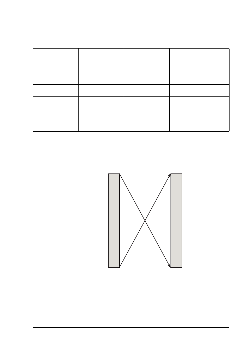
Table 3: Frequency ranges for C-Band BUCs (Extended)
Overview
LO frequency
(MHz)
f
LO
Tuning range of
L-Band
(MHz)
f
IF
Output
frequency
(MHz)
f
RF
See...
7300 950–1450 5850–6 350 Figure 3 on page 9
7375 950–1525 5850–6 425 Figure 4 on page 10
7600 950–1750 5850–6 650 Figure 5 on page 10
7675 950–1750 5925–6 725 Figure 6 on page 11
Figure 3: C-Band frequency conversion plan at an LO frequency of 7300 MHz
450 MHz1 350 MHz6
950 MHz
IF input RF output
Block Up Converter Systems 6700/6900 series User Guide 9
850 MHz5
Page 20

Overview
Figure 4: C-Band frequency conversion plan at an LO frequency of 7375 MHz
525 MHz1 425 MHz6
950 MHz
IF input RF output
850 MHz5
Figure 5: C-Band frequency conversion plan at an LO frequency of 7600 MHz
750 MHz1 650 MHz6
950 MHz
IF input RF output
850 MHz5
10 Block Up Converter Systems 6700/6900 series User Guide
Page 21

Overview
Figure 6: C-Band frequency conversion plan at an LO frequency of 7675 MHz
750 MHz1 725 MHz6
950 MHz
IF input RF output
925 MHz5
Ku-Band
Figure 7 and Figure 8 show the frequency conversion plans
for each LO frequency of the Ku-Band BUCs.
Table 4: Frequency ranges for Ku-Band BUCs (Standard)
LO frequency
(MHz)
f
LO
Tuning range of
L-Band
(MHz)
f
IF
Output
frequency
(MHz)
f
RF
See...
15450 950–1450 14000–14500 Figure 7 on page 12
Block Up Converter Systems 6700/6900 series User Guide 11
Page 22
Overview
Table 5: Frequency ranges for Ku-Band BUCs (Extended)
LO frequency
(MHz)
f
LO
Tuning range of
L-Band
(MHz)
f
IF
Output
frequency
(MHz)
f
RF
See...
15450 950–1450 14000–14 500 Figure 7 on page 12
15450 950–1700 13750–14 500 Figure 8 on page 13
Figure 7: Ku-Band frequency conversion plan for BUCs that cover the Standard frequency band
450 MHz1 500 MHz14
950 MHz
IF input RF output
12 Block Up Converter Systems 6700/6900 series User Guide
000 MHz14
Page 23
Overview
Figure 8: Ku-Band frequency conversion plan for BUCs that cover the Extended frequency band
700 MHz1
1
450 MHz
950 MHz
Power supply options
The power supply option for your BUC is indicated in the
model number on the serial number label. For information on
how to interpret the model number see page 111, BUC model
and redundancy system numbers.
Some BUCs are powered by 48 V DC or 24 V DC. Other
BUCs are powered via an AC mains input.
IF input RF output
500 MHz14
14
000 MHz
13
750 MHz
Table 6: Power supply options for BUCs
Input Power supply option Feed to BUC
DC 24 V/48 V via IF cable or separate
cable and connector
AC 94–275 V AC via separate cable and
connector
Block Up Converter Systems 6700/6900 series User Guide 13
Page 24

Overview
NOTE
NOTE
BUCs that are AC-powered, also draw current
from the DC power input on the IF input cable
for remote alarm indication purposes only.
Certain BUCs with external DC power
connectors may also have auto-sensing circuits,
and can be powered from either the external
connector or via the IF INPUT connector. If
both connectors are powered, the external
connector is automatically selected.
14 Block Up Converter Systems 6700/6900 series User Guide
Page 25

LNB
Overview
The frequency band that is down converted by the LNB is
indicated on the model label of the LNB.
C-Band
The C-Band LNB is supplied for operation on the frequency
band 3400 to 4200 MHz. It has an LO frequency of
5150 MHz.
NOTE The C-Band LNB is frequency inverting.
Ku-Band
The Ku-Band LNB may be supplied for operation in one of
three frequency band options listed in Table 7.
Table 7: Frequency band options for the Ku-Band LNB
Band option Receive frequency
(MHz)
1 10950–11700 10000 950–1700
2 11700–12 200 10 750 950–1450
3 12250–12750 11300 950–1450
Block Up Converter Systems 6700/6900 series User Guide 15
LO frequency
(MHz)
L-Band output
frequency
(MHz)
Page 26

Overview
Redundancy systems
The Codan Redundancy Controller 6586 is used to control two
BUCs and two LNBs (when used) in a redundancy system.
When a detectable fault occurs in the on-line BUC, and the
off-line BUC is serviceable, the redundancy controller
switches over the two BUCs. The interruption to traffic is
typically less than one second. Transmit/receive systems also
include two LNBs, which are switched in parallel with the
BUCS. In such systems, simultaneous switching of both BUC
and LNB occurs when a fault is detected in either the on-line
BUC or the on-line LNB. This is known as stream-switching.
A typical BUC-LNB system comprises:
•a BUC
• an LNB (in transmit/receive systems only)
• a TRF (optional)
• appropriate connecting cables
A typical redundancy system comprises:
•two BUCs
• two LNBs (in transmit/receive systems only)
• an Redundancy Controller 6586
• one or two RF waveguide switches or a combined RF
waveguide/coaxial switch
• a Remote Controller 6570 (optional)
For information on the remote controller see the Hand-held
and Remote Controller 6560/6570 User Guide.
16 Block Up Converter Systems 6700/6900 series User Guide
Page 27

Redundancy system control
You can control and monitor the redundancy switching
equipment:
• locally, using a Hand-held Controller 6560 connected to
the BUC 1 Serial/BUC 2 Serial connectors on the
redundancy controller
• remotely, using the optional Remote Controller 6570
connected to the Auxiliary I/O connector on the
redundancy controller
The redundancy controller
The redundancy controller is the main component of the
redundancy system. It controls the switching between the
on-line and off-line BUC and LNB. The redundancy controller
is normally installed on the antenna pedestal near the two
BUC systems. The redundancy controller is powered from the
AC mains supply.
Overview
The redundancy controller performs the following functions:
• monitors the Stream 1 and Stream 2 equipment for faults
• monitors the RF waveguide switches for switch faults
• controls the RF waveguide switch positions
• directs the IF paths via high frequency relays and splitter
networks
• supplies power to the BUCs, LNBs (when used), and
optional Remote Controller 6570
The redundancy controller communicates with the BUCs via
relay contacts. The serial interfaces of the BUCs are kept
available for separate use. DC supply connections and isolated
contact closures are available on the Auxiliary I/O connector
of the redundancy controller.
The control panel inside the redundancy controller is shown in
Figure 9.
Block Up Converter Systems 6700/6900 series User Guide 17
Page 28

Overview
Figure 9: Control panel on the redundancy controller
BUC 1
Redundancy
Controller
Tx IF
Status
Rx IF
Voltage
Selection
Remote
Controller BUC 1 BUC 2 LNB 1* LNB 2*
* Not used in transmit-only systems
LNB 1*
BUC 2
LNB 2*
Fuse status LEDs
BUC
Switch
LNB
Switch*
LED indicators
The control panel of the redundancy controller has groups of
LEDs that indicate the status of the redundancy system and its
fuses. The colours and functions of these LEDs are described
in Table 12 on page 60.
18 Block Up Converter Systems 6700/6900 series User Guide
Page 29

Overview
Switches
The control panel of the redundancy controller has one switch.
The function of this switch is to select the AC input voltage
(115 or 230 VAC).
Connectors
The connector panel is located at the bottom of the
redundancy controller.
Figure 10: Connector panel on the redundancy controller
BUC Switch Control
LNB Switch Control
BUC 1 Serial BUC 1 Control
BUC 2 Serial
BUC 2 Control
AC Power Input
Auxiliary I/O
Rx IF Input 2Rx IF OutputRx IF Input 1Tx IF Output 2Tx IF InputTx IF Output 1
Block Up Converter Systems 6700/6900 series User Guide 19
Page 30

Overview
How the redundancy controller works
When you power up the system, the redundancy controller
uses the current status of the BUC Switch and LNB Switch
(when used) to select the on-line stream.
If the redundancy controller detects that the
NOTE
When the redundancy controller is operating, it monitors the
two BUC and LNB (when used) streams for faults. When a
detectable fault occurs in the on-line BUC and LNB, and the
off-line BUC and LNB is serviceable, the redundancy
controller switches over the two streams. The interruption to
traffic is typically less than one second.
The redundancy controller switches:
• the receive IF signals between the LNBs (when used)
and the modem equipment
• the transmit RF signals between the BUCs and the
transmit antenna port
switches are inconsistent, or cannot be detected,
it selects Stream 1.
• the receive RF signal between the receive antenna port
and the LNBs (when used)
The transmit IF signal is not switched. Rather, a splitter allows
the transmit IF signal to feed both BUCs simultaneously. In
transmit-only systems, a transmit-only connector assembly is
supplied and fitted to the LNB Switch Control connector.
20 Block Up Converter Systems 6700/6900 series User Guide
Page 31

Overview
BUC faults
The redundancy controller uses a PLD to monitor the alarm
signals from both BUCs. The BUCs send alarm signals via
cables connected to the 14-way BUC 1 Control and BUC 2
Control connectors on the redundancy controller.
Red BUC 1/BUC 2 LEDs on the control panel of the
redundancy controller indicate that there is a fault with the
corresponding BUC or LNB. In transmit-only systems,
receive stream faults are not indicated. You should observe the
LED indicators on the BUC for details of the alarm condition.
For information on the LED indications on the BUC see
Table 11 on page 59. You can connect a Hand-held
Controller 6560 or a PC running terminal-emulating software
to the BUC 1 Serial and BUC 2 Serial connectors on the
redundancy controller, then diagnose the BUC faults as
required. For more information on using the hand-held
controller see the Hand-held and Remote Controller
6560/6570 User Guide. For more information on using serial
commands on a terminal see page 63, Serial interface
commands.
If you are using remote monitoring and control via a Remote
Controller 6570, the Fault LED for a BUC will illuminate if a
fault is detected. You can use the Faults menu in the remote
controller to diagnose the fault, and the Reset menu to clear
latched faults. For more information on using the remote
controller see the Hand-held and Remote Controller
6560/6570 User Guide.
Power supply
The redundancy controller is powered from the AC mains
supply.
Block Up Converter Systems 6700/6900 series User Guide 21
Page 32

Overview
Auxiliary I/O interface of the redundancy controller
The Auxiliary I/O interface of the redundancy controller
enables you to perform the following functions remotely:
• monitor operation of the redundancy switching system
using the isolated relay contacts
• switch streams using external signals
Most of the remote control functions are achieved by
grounding the appropriate control signal to 0 V.
The redundancy controller does not have a
serial remote control facility. However, serial
NOTE
remote stream switching and monitoring of the
redundancy system alarms are available using
the BUC command set via either of the BUC 1
Serial/BUC 2 Serial connectors.
For details about the Auxiliary I/O interface of the redundancy
controller see page 51, Accessing the Auxiliary I/O interface
on the redundancy controller.
22 Block Up Converter Systems 6700/6900 series User Guide
Page 33

RF waveguide switches
RF waveguide switches control both the receive and transmit
RF paths. The switches direct signals for both on-line and offline BUCs and LNBs (when used). Transmit/receive C-Band
systems may use either two RF waveguide switches or one
combined RF waveguide/coaxial switch. Transmit/receive
Ku-Band systems use two RF waveguide switches only.
Transmit-only C-Band or Ku-Band systems use only a single
RF waveguide switch.
Systems using two RF waveguide switches
In the receive path, a receive RF waveguide switch directs the
received RF from the receive port of the antenna feed to one of
the LNBs. The LNB waveguide inputs are coupled to ports 1
and 3 of the LNB switch. The switch is coupled via port 2 to
the WR229 (C-Band) or WR75 (Ku-Band) receive port of the
antenna. A blanking plate normally protects port 4 from the
weather.
In the transmit path, a transmit RF waveguide switch directs
the transmitted RF from the on-line BUC to the transmit port
of the antenna feed. The RF from the off-line BUC is directed
to either a coaxial or a waveguide load.
Overview
For transmit RF, the waveguide outputs of the BUCs are
connected to the WR137 (C-Band) or WR75 (Ku-Band) BUC
switch via short waveguide sections to ports 1 and 3. Port 2 of
the switch connects to the antenna via flexible waveguide. A
load or power attenuator terminates port 4 on the switch.
The redundancy controller verifies RF waveguide switching
by monitoring the tell-back contacts of both switches. If the
tell-back contacts indicate an abnormal condition, the BUC
Switch or LNB Switch LEDs on the control panel of the
redundancy controller illuminate red.
Block Up Converter Systems 6700/6900 series User Guide 23
Page 34

Overview
Systems using a combined RF waveguide/coaxial switch (C-Band only)
In the receive path, a receive RF waveguide switch directs the
received RF from the receive port of the antenna feed to one of
the LNBs.
In the transmit path, an RF coaxial switch directs the
transmitted RF from the on-line BUC to the transmit port of
the antenna feed. The RF from the off-line BUC is directed to
an appropriately-rated termination. The combined RF
waveguide/coaxial switch is controlled by a single cable,
which is connected to the LNB Switch Control connector
on the redundancy controller. The BUC Switch Control
connector is not used. The redundancy controller
automatically detects the presence of a combined switch and
configures its monitoring accordingly.
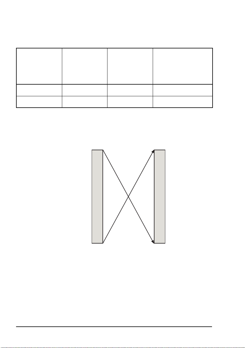
The combined RF waveguide/coaxial switch combines
waveguide and coaxial switching in a single assembly. The
switch is an electrically operated, 4-port WR229 waveguide
transfer switch, which is mechanically integrated with a 4-port
coaxial transfer switch for transmit RF.
The LNBs are directly coupled to ports 1 and 3 of the
combined RF waveguide/coaxial switch. The switch is
coupled via port 2 to the WR229 receive port of the antenna.
A blanking plate normally protects port 4 from the weather.
Coaxial cable connects the BUCs to ports 1 and 3 of the
N-type switch. The transmit antenna feed connects to port 2 of
the switch. A load or power attenuator connects to port 4.
The redundancy controller verifies RF waveguide switching
by monitoring the tell-back contacts to the combined RF
waveguide/coaxial switch. If the tell-back contacts indicate an
abnormal condition, the LNB Switch LEDs on the control
panel of the redundancy controller illuminate red.
In the combined RF waveguide/coaxial switch
NOTE
installation, the BUC Switch LEDs on the
control panel of the redundancy controller will
not illuminate.
24 Block Up Converter Systems 6700/6900 series User Guide
Page 35

Overview
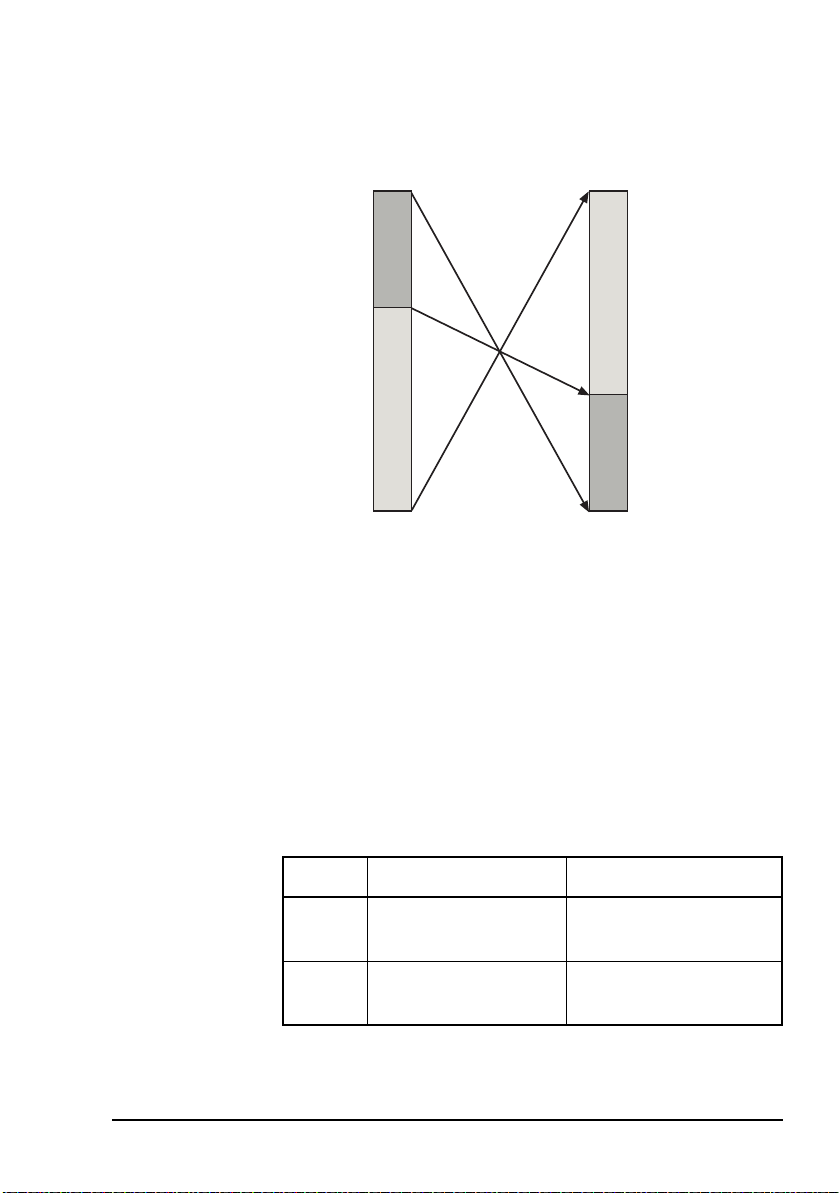
Systems using a single transmit RF waveguide switch (transmit-only)
In the transmit path, a single transmit RF waveguide switch
directs the transmitted RF from the on-line BUC to the
transmit port of the antenna feed. The RF from the off-line
BUC is directed into an appropriately-rated termination. The
switch is controlled by a cable connected to the LNB Switch
Control connector.
The switch is an electrically operated, 4-port WR137 (for
C-Band) or WR75 (for Ku-Band) waveguide transfer switch.
The BUCs are connected to ports 1 and 3 of the switch. The
switch is coupled via port 2 to the transmit port of the antenna.
A load or power attenuator connects to port 4.
The redundancy controller verifies RF waveguide switching
by monitoring the tell-back contacts to the RF waveguide
switch. If the tell-back contacts indicate an abnormal
condition, the BUC Switch LEDs on the control panel of the
redundancy controller illuminate red.
Block Up Converter Systems 6700/6900 series User Guide 25
Page 36

Overview
The Remote Controller 6570 and Hand-held Controller 6560
The Remote Controller 6570 provides remote control and
monitoring facilities of the BUCs at a convenient indoor
location. The remote controller is connected via its BUC
Interface connector to the Auxiliary I/O connector on the
redundancy controller using the cable supplied.
The Hand-held Controller 6560 provides local control and
monitoring facilities of the BUCs at the outdoor-mounted
redundancy controller. A hand-held controller may be
connected to the BUC 1 Serial or BUC 2 Serial connector.
Alternatively, a BUC may be directly controlled by the handheld controller by disconnecting the M/C cable from the
M/C connector on the BUC, and connecting the hand-held
controller in its place.
26 Block Up Converter Systems 6700/6900 series User Guide
Page 37

2Installation
This section contains the following topics:
Unpacking the equipment (28)
Installing the BUC equipment (28)
Cable recommendations (32)
Serial interfaces (37)
Connecting the serial interface (39)
Monitor and control interface of the BUC (40)
Installing the redundancy system (42)
Serial interfaces of the BUCs from the redundancy
controller (50)
Accessing the Auxiliary I/O interface on the redundancy
controller (51)
Setting up the redundancy switching equipment (53)
CODAN
Block Up Converter Systems 6700/6900 series User Guide 27
Page 38

Installation
Unpacking the equipment
Ensure that the packing boxes are upright as indicated by the
printing on the boxes. Open each box and check for signs of
damage to the equipment. If you notice any damage, contact
Codan immediately to obtain an RMA. Failure to contact
Codan before returning the unit may result in any warranty
being void.
Installing the BUC equipment
All equipment that is mounted outdoors must be
adequately weatherproofed.
Ensure all waveguide joints are properly sealed
WARNING
with the appropriate gasket.
Use self-amalgamating tape to seal connectors
and cable entry points from the connector to the
cable sheath.
Water is the most common cause of poor
CAUTION
WARNING
28 Block Up Converter Systems 6700/6900 series User Guide
performance in VSAT installations. Ensure that
all cables and waveguide junctions are properly
sealed.
A radiation hazard exists if the BUC is operated
with its RF output unterminated (see page 123,
Radiation safety).
Page 39

Installation
TRF and LNB
The TRF and LNB are normally mounted directly on the
antenna feed structure.
The LNB obtains the required +15 to +24 V DC power and, in
certain cases, the 10 MHz reference signal from a compatible
L-Band modem. The modem is connected to the receive
output connector of the LNB.
BUC
BUCs are supplied with either N-type or waveguide outputs.
A mounting kit is supplied with the BUC. Some mounting kits
allow the BUC to be mounted on the boom or pedestal of the
antenna. Other kits may also be available for different
mounting options. Contact your antenna manufacturer if you
have specific installation requirements.
Cables
Use an IF coaxial cable to connect the modem to the BUC (see
page 32, Cable recommendations). It is recommended that you
use the same type of cable to connect the modem to the LNB.
If you are using the RS232/422 serial interface, use an M/C
cable to connect the BUC to a PC (see page 40, Monitor and
control interface of the BUC).
DC power connection
There are two types of BUCs that are DC-powered: those
powered via the IF INPUT connector, and those powered via
an external connector.
BUCs that are powered via the IF INPUT connector receive
DC power from a source via the IF cable. See BUC
specifications or compare your BUC model number against
Table 27 on page 111 for the exact voltage range of your BUC.
Block Up Converter Systems 6700/6900 series User Guide 29
Page 40

Installation
BUCs that are externally powered from a DC source require
appropriate DC power from an external source. See BUC
specifications or compare your BUC model number against
Table 27 on page 111 for the exact voltage range of your BUC.
Certain BUCs with external DC power
connectors may also have auto-sensing circuits,
NOTE
AC mains connection
AC-powered BUCs operate with any AC input voltage in the
range 115–230 VAC. Check BUC specifications for the exact
voltage range of your BUC.
and can be powered from either the external
connector or via the IF INPUT connector. If
both connectors are powered, the external
connector is automatically selected.
WARNING
To connect the BUC to the AC mains:
Voltages outside of these limits may cause
damage to the BUC.
1 Connect the AC power lead to the AC mains supply.
Before applying power to the BUC, ensure
that the installation complies with the
WARNING
safety precautions listed on page 123,
Electromagnetic compatibility and safety
notices.
1 Ensure the isolating switch for the AC supply is switched
off.
1 Connect the AC power lead to the AC INPUT connector
on the BUC.
If you need to make your own AC mains cable, or reterminate
the cable supplied, Table 8 lists the pin connections and
describes the input functions available on the AC INPUT
connector on the BUC.
30 Block Up Converter Systems 6700/6900 series User Guide
Page 41

Installation
Table 8: Pinouts of the AC INPUT connector (Amphenol T 3110 000)
Pin Description
1 Neutral
2 Not connected
3 Active
Protective earth
It is recommended that BUCs are installed as close as possible
to the antenna feed to minimise losses.
Heavier BUCs may need to be mounted further
CAUTION
down the boom to minimise the mechanical
leverage load on the antenna.
If the waveguide output of each BUC is attached directly to
the RF waveguide switch with a rigid connection, ensure that
there are no undue stresses on the waveguide section when the
flange hardware is tightened. Tighten the BUC mounting
screws last. The long mounting rails have oversized holes to
enable the BUC to be secured in the exact position required,
which avoids stressing the rigid waveguide component.
Block Up Converter Systems 6700/6900 series User Guide 31
Page 42

Installation
Cable recommendations
Table 9 lists the recommended specifications for IF coaxial
cables used in your system. These specifications place
restrictions on the maximum length of the transmit IF cable.
The limiting factor is most likely the 20 dB maximum cable
loss. Cables that have 20 dB cable loss at L-Band frequencies
usually have DC loop resistances much less than those shown
below.
Table 9: Recommendations for IF coaxial cables
Characteristic Recommendation
Cable loss at operating
frequency
DC loop resistance 2 Ω maximum (+48 V BUC)
Screening 100 dB minimum
Nominal impedance 50 Ω
Connectors BUC end: N-type male
Cable loss specification
The recommended maximum cable loss is derived from the
maximum output power normally provided by modems and
the maximum gain of the BUC.
20 dB maximum
1 Ω maximum (+24 V BUC)
connector
Indoor end: connector to suit the
modem used
32 Block Up Converter Systems 6700/6900 series User Guide
Page 43

Installation
DC loop resistance specification
The maximum DC loop resistance is determined by the DC
power drawn by a BUC and its minimum operating input
voltage. Some BUCs are not powered via the cable, so the DC
loop resistance of the IF cable is not a consideration for such
BUC installations.
Cable lengths
Frequency
(MHz)
CAUTION
To ensure correct operation, the DC loop
resistance figure must not be exceeded.
Cable screening specification
Cable screening is derived from regulatory requirements
related to the radiation of spurious signals from the antenna.
Screening is more critical if the BUC is co-located with other
radio transmitting equipment, for example, mobile-phone
towers.
Table 10 shows the maximum lengths of different types of
cables to ensure the 20 dB loss recommendation is not
exceeded. The cable lengths are shown in metres and feet.
Table 10: Cable lengths resulting in a 20 dB loss
RG223
(m (ft))
Belden 9914
(m (ft))
Belden 9913F
(m (ft))
Times
Microwave
LMR-400
(m (ft))
950 43 (141) 104 (341) 125 (410) 150 (492)
1450 34 (111) 81 (266) 99 (325) 120 (394)
1700 31 (102) 74 (243) 91 (299) 111 (364)
1750 31 (102) 73 (240) 89 (292) 109 (358)
Block Up Converter Systems 6700/6900 series User Guide 33
Page 44

Installation
IF levels
The figures and tables in this section show the single carrier IF
levels required to achieve rated P1dB output power from the
BUC using various types and lengths of IF cables. Your actual
IF levels may be different from those shown if you are
operating with multiple carriers and you require output back
off to control intermodulation product levels.
Examples are provided for short cables (with a 3 dB loss) and
long cables (with a 20 dB loss).
The figures in this section are provided as examples only. You
should determine the loss of your selected cable from its
length and your operating frequency (see Table 10 on
page 33). You can then set the modem IF output level and the
BUC attenuator to achieve the required output power.
As a general principle, you should set the BUC attenuator at
the highest possible attenuation setting given the available
modem IF output power and the cable loss. This reduces the
susceptibility of the system to external interference.
34 Block Up Converter Systems 6700/6900 series User Guide
Page 45

Installation
Using short IF cables
Figure 11 shows the IF levels required when using short IF
cables such as the following:
• 5 m RG223
• 12 m 9914
• 15 m 9913F
•18m LMR-400
Figure 11: IF levels required for short cables
BUCIF cableModem
Gain
Input/output
level
Refer to the relevant specifications sheets for the detailed specifications for your BUC
Block Up Converter Systems 6700/6900 series User Guide 35
16 dBm 19 dBm
3 dB
BUC gain
attenuator
setting
19 dBm +
(BUC gain
attenuator setting)
Page 46
Installation
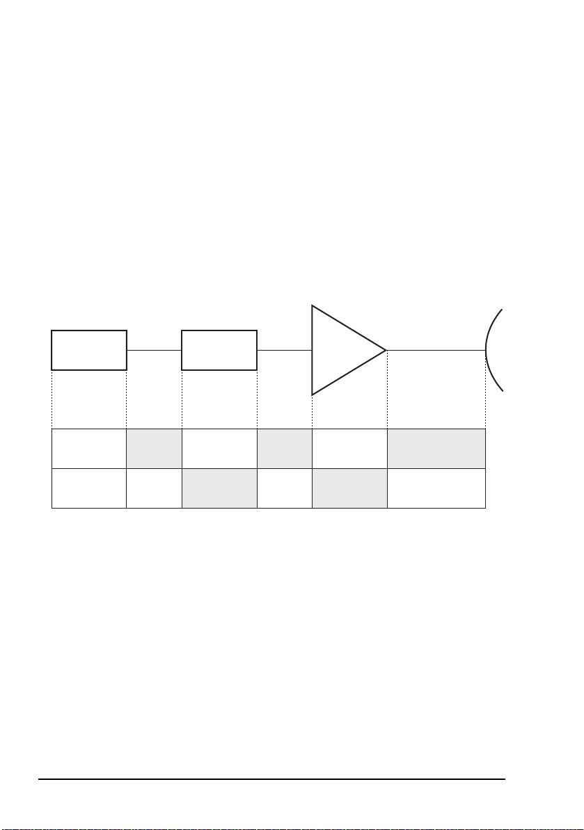
Using long IF cables
Figure 12 shows the IF levels required when using long IF
cables such as the following:
• 34 m RG223
• 80 m 9914
• 100 m 9913F
• 120 m LMR-400
Figure 12: IF levels required for long cables
BUCIF cableModem
Gain
Input/output
level
Refer to the relevant specifications sheets for the detailed specifications for your BUC
36 Block Up Converter Systems 6700/6900 series User Guide
7 dBm 27 dBm
20 dB
BUC gain
attenuator
setting
27 dBm +
(BUC gain
attenuator setting)
Page 47

Serial interfaces
The following serial interfaces are provided:
• RS232 and RS422/485 available on the M/C connector
on the BUC
• FSK available on the IF INPUT connector on the BUC
RS232 interface
The RS232 serial interface supports both the ASCII and the
Codan packet protocols simultaneously. Responses to
commands are returned in the same protocol format as they
are sent. The RS232 serial interface operates with the
following parameters:
data rate 9600 bps
word length 8 bits
parity none
Installation
stop bit 1
The fixed data rate and protocol simplifies the connection
during installation and commissioning, and enables a PC
running a terminal-emulation program to be used to configure
the BUC. For information on protocols, contact your Codan
representative.
The BUC is able to detect the connection of an RS232
interface. When an RS232 interface is used, the BUC inhibits
the use of the Set and Reset commands on the RS422/485 and
FSK interfaces. View and Output commands can still be used
on these interfaces. This functionality is provided for safety
reasons.
If you disabled transmission, don’t forget to
NOTE
Block Up Converter Systems 6700/6900 series User Guide 37
re-enable it before you remove the RS232
connection.
Page 48

Installation
For example, a technician working on a BUC at the antenna
can make an RS232 connection and disable transmissions.
Transmissions cannot be re-enabled at another source, but the
other interfaces can still monitor the BUC parameters. When
the RS232 connection is removed and transmission is restored
using the RS232 interface, normal monitor and control
operation is restored.
RS422/485 interface
The RS422/485 interface can be operated in either 2-wire or
4-wire mode. The RS422/485 interface enables monitor and
control of the BUC over long distances using other protocols
that are not available for use with the RS232 interface.
FSK interface
The FSK interface enables monitor and control of the BUC
over long distances using other protocols that are not available
for use with the RS232 interface. The FSK interface does not
require an extra monitor and control serial cable, but does
require a modem with FSK monitor and control capability. If
an appropriate modem is not available, contact your Codan
representative to find out what accessories are available to
access the FSK interface.
38 Block Up Converter Systems 6700/6900 series User Guide
Page 49

Connecting the serial interface
To set the operating parameters of the BUC, the BUC must be
connected to a terminal (for example, a Hand-held Controller
6560, a Remote Controller 6570, a PC, or an organiser
emulating a terminal).
The connection may be permanent as part of the installation or
temporary for the purpose of setting the operating parameters
of the BUC.
Permanent interface connection
A permanent interface connection can be provided via the
monitor and control interface of the BUC (see Figure 13 on
page 41). The RS232 serial interface may only be used for
distances less than 15 m. The RS422/485 serial interface may
be used for distances up to approximately 1 km.
The Remote Controller 6570 is designed as a permanent
interface connection and is supplied with a standard 50 m
cable.
Installation
Temporary interface connection
A serial interface cable is available to connect the BUC to the
RS232 serial port of a PC or an organiser emulating a
terminal, or you may connect a Hand-held Controller 6560.
If using a PC, connect the cable between the M/C connector of
the BUC and the serial port of the PC. This cable provides a
14-way female MS-style connector to 9-way D-type female
connector for connection to the PC. If connection to a 25-way
D-type serial port is required, use a standard 25-way female to
9-way male adaptor.
Block Up Converter Systems 6700/6900 series User Guide 39
Page 50

Installation
Monitor and control interface of the BUC
The monitor and control interface of the BUC provides a relay
contact to indicate the fault status of the BUC. See Figure 13
for the pin assignments of the M/C connector. A
MIL-C-26482 12-14P connector (for example,
MS3116F12-14P) is required to mate with the M/C connector.
40 Block Up Converter Systems 6700/6900 series User Guide
Page 51

Installation
Figure 13: Monitor and control interface of the BUC
+2.5 V
+10 V
+5 V
+12 V
1 k
1 k
10 k
+5 V
1 k
1 k
+5 V
120
120
M
H
C
*
L
B
*
F
D
E
A
K
J
+10 V DC (nominal)
output (150 mA max.)
0 V
RS422/485 Rx+
RS422/485 Rx
RS422/485 Tx+/Rx+
(RS422/485 TxB/RxB)
RS422/485 Tx/Rx
(RS422/485 TxA/RxA)
Not connected
RS232 RxD
RS232 TxD
Summary Alarm
(open on alarm
30 V @ 1 A max.)
+
+
+
Block Up Converter Systems 6700/6900 series User Guide 41
1k5
1k5
1k5
+5 V
+5 V
R
N
P
LNB Fault
Redundancy Controller
Fault
On-line Input/Output
*Bus termination resistors
Page 52

Installation
Installing the redundancy system
Mounting the redundancy controller
The redundancy controller has two mounting flanges. Each
flange has 10 mounting holes. If you are going to use the
mounting kit supplied, fitting instructions are provided in the
kit.
Mount the redundancy controller upright on or near the
antenna structure. A protected position is preferable however,
the redundancy controller can withstand exposure to outdoor
conditions.
Installing separate transmit and receive RF waveguide switches
WARNING
Transmit RF waveguide switch
To install the transmit RF waveguide switch (BUC switch):
Handle the switches with care. They are easily
damaged.
1 Connect ports 1 and 3 of the transmit RF waveguide
switch to the BUC outputs using the waveguide sections
and flange kits as shown in the mounting drawings.
NOTE
NOTE
42 Block Up Converter Systems 6700/6900 series User Guide
In C-Band installations, use the appropriate
flange kit.
In Ku-Band installations, ensure the
appropriate o-ring is used, otherwise
sealing will be compromised or correct
mating of the waveguide flanges will not
be possible.
Page 53

Installation
1 Connect port 2 of the transmit RF waveguide switch to
the transmit flange of the antenna feed using gasket kits
and rigid or flexible waveguide as appropriate.
If connecting the Ku-Band transmit RF
waveguide switch to a waveguide section
NOTE
that has clearance holes for 6-32 UNC
hardware, a waveguide adaptor kit is
available.
1 Connect the off-line BUC load to port 4 of the transmit
RF waveguide switch as shown in the mounting
drawings.
CAUTION
NOTE
Ensure all joints are completely
weatherproof.
Spare flange kits are provided with the
redundancy package. The universal
Ku-Band flange kit contains a selection of
flat gaskets and circular cross-section
gaskets (both large and small
cross-sectional diameter).
1 In transmit-only systems, fit the transmit-only connector
assembly to the LNB Switch Control connector.
1 Connect the transmit RF waveguide switch to the BUC
Switch Control connector using the cable supplied.
Block Up Converter Systems 6700/6900 series User Guide 43
Page 54

Installation
Receive RF waveguide switch (transmit/receive systems only)
To install the receive RF waveguide switch (LNB switch):
1 Fit the TRF (if used) to the receive port of the antenna
feed using the appropriate flange kit for C-Band and
Ku-Band, selecting the correct gasket.
1 Hold waveguide port 2 of the receive RF waveguide
switch against the receive port of the antenna feed or
TRF (if fitted). Decide which way the switch is to face.
1 For Ku-Band installations, attach the 2" rigid WR75
waveguide sections to ports 1 and 3 of the receive RF
waveguide switch using the appropriate flange kit.
1 Attach the LNBs to:
• ports 1 and 3 of the receive RF waveguide switch using
the appropriate flange kit for C-Band
• the 2" rigid waveguide sections using the appropriate
flange kit for Ku-Band
For Ku-Band installations, ensure the
appropriate o-ring is used, otherwise
NOTE
sealing will be compromised or correct
mating of the waveguide flanges will not
be possible.
1 Clamp the gaskets tightly to ensure perfect seals.
1 If the blanking plate was not factory fitted, attach it to
port 4 of the receive RF waveguide switch using the
appropriate flange kit.
1 If you want to allow for dry air pressurisation, fit the
supplied air nozzle to the blanking plate. If this is not
required, fit the M5 screw with seal into the blanking
plate.
1 Attach the receive RF waveguide switch to the receive
port of the antenna feed using the appropriate flange kit.
44 Block Up Converter Systems 6700/6900 series User Guide
Page 55

Installation
If connecting the Ku-Band receive RF
waveguide switch to a receive port of the
antenna feed that has clearance holes for
6-32 UNC hardware, a waveguide adaptor
kit is available.
NOTE
Spare flange kits are provided with the
redundancy package. The universal
Ku-Band flange kit contains a selection of
flat gaskets and circular cross-section
gaskets (both large and small crosssectional diameter).
1 Connect the receive RF waveguide switch to the LNB
Switch Control connector using the cable supplied.
Installing the combined RF waveguide/coaxial switch (C-Band transmit/receive systems only)
WARNING
To install the combined RF waveguide/coaxial switch:
Handle the switch with care. It is easily
damaged.
1 Fit the TRF (if used) to the receive port of the antenna
feed using the appropriate flange kit.
1 Hold waveguide port 2 of the combined RF
waveguide/coaxial switch against the antenna receive
feed. Decide which way the switch is to face.
1 Attach the LNBs to ports 1 and 3 of the RF waveguide
section of the switch using the appropriate flange kit.
1 Clamp the gaskets tightly to ensure perfect seals.
1 If the blanking plate was not factory fitted, attach it to
port 4 of the waveguide section of the switch using the
appropriate flange kit (see the mounting and
interconnection drawings).
Block Up Converter Systems 6700/6900 series User Guide 45
Page 56

Installation
1 If you want to allow for dry air pressurisation, fit the
supplied air nozzle to the blanking plate. If this is not
required, fit the M5 screw with seal into the blanking
plate.
1 Connect the off-line BUC termination to port 4 of the
coaxial section of the switch as shown in the mounting
and interconnection drawings.
NOTE
In some configurations, the termination
consists of multiple parts.
1 Connect the outputs of the BUCs to the corresponding
N-type connectors of the coaxial section of the switch
using the coaxial cables supplied.
1 Connect port 2 of the coaxial section of the switch to the
transmit port of the antenna feed using the coaxial cable
supplied.
1 Seal all N-type connections with self-amalgamating tape.
CAUTION
NOTE
Ensure all joints are completely
weatherproof.
Spare flange kits are supplied with the
redundancy package to provide for various
installation requirements.
1 Connect the combined RF waveguide/coaxial switch to
the LNB Switch Control connector using the cable
supplied.
NOTE
The BUC Switch Control connector is
not used in this configuration.
46 Block Up Converter Systems 6700/6900 series User Guide
Page 57

Connecting the power cables
The redundancy controller is AC mains powered.
To connect the power cable to the redundancy controller:
1 Connect the supplied cable to the AC Power Input
connector on the redundancy controller.
Installation
Block Up Converter Systems 6700/6900 series User Guide 47
Page 58

Installation
Connecting the control cables
To connect the control cables:
1 Connect the BUC 1 Control connector and the BUC 2
Control connector on the redundancy controller to the
corresponding M/C connector on each BUC using the
control cables supplied.
For high-power BUC systems, connect the BUC 1
Control connector and the BUC 2 Control connector
on the redundancy controller to the corresponding
M/C connector on each BUC and the corresponding
CONTROL connector on each high-power SSPA using
the specific control cables supplied.
Connecting the IF from the redundancy controller to the BUCs
To connect the IF cables:
1 Connect the Tx IF Output 1 connector and the Tx IF
Output 2 connector on the redundancy controller to the
corresponding IF INPUT connector on each BUC using
the coaxial cables supplied.
Connecting the IF cables between an L-Band IF modem (or other equipment) and the redundancy controller
To connect the IF cables:
1 Connect the transmit IF output connector on the L-Band
IF modem (or other equipment) to the Tx IF Input
connector on the redundancy controller using a suitable
coaxial cable.
1 In systems other than transmit-only, connect the receive
IF input connector on the L-Band IF modem (or other
equipment) to the Rx IF Output connector on the
redundancy controller using a suitable coaxial cable.
48 Block Up Converter Systems 6700/6900 series User Guide
Page 59

Connecting the IF from the LNBs to the redundancy controller
To connect the IF cables:
1 Connect the corresponding N-type IF output connector
on each LNB to the Rx IF Input 1 connector and the Rx
IF Input 2 connector on the redundancy controller using
the coaxial cable supplied.
Grounding the installation
To ground the installation:
1 Connect a separate earth strap from the protective earth
terminal on each unit directly to the common earth stake.
Installation
Block Up Converter Systems 6700/6900 series User Guide 49
Page 60

Installation
Serial interfaces of the BUCs from the redundancy controller
The M/C connector on each BUC includes the serial interface
of the BUC. Although the redundancy controller plugs into
this connector, the redundancy controller uses relay contacts to
communicate with the BUC.
You can access the serial interface of each BUC via the
14-way BUC 1 Serial or BUC 2 Serial connector on the
redundancy controller. These connectors are suitable for
temporary connection of a PC or Hand-held Controller 6560
as they have the same RS232 serial pin connections as the
M/C connector on the BUC.
The RS485 serial interfaces for both BUCs are included in the
19-way Auxiliary I/O connector interface of the redundancy
controller for remote monitor and control applications via the
Remote Controller 6570.
50 Block Up Converter Systems 6700/6900 series User Guide
Page 61

Installation
Accessing the Auxiliary I/O interface on the redundancy controller
Remote control and monitoring of the redundancy switching
system is accessible via the 19-way Auxiliary I/O connector
on the redundancy controller.
To use this 19-way connector, you need a 19-way
Mil-C-26482 series plug, part number MS3116J14-19P.
Figure 14 on page 52 shows the monitor and control interface
at the Auxiliary I/O connector of the redundancy controller.
Contacts are shown in their de-energised state.
Relay contacts indicate the following faults and operational
status of the redundancy system (the four relay contacts share
a common contact connection):
• Stream 1 Fault
• Stream 2 Fault
• Stream Selected
• Redundancy Controller Fault
Inputs are provided to allow remote control via contact
closures:
• control source
• Auto or Manual Mode
• stream selection
The RS485 connections parallel the two BUC RS485
interfaces to enable remote control of both BUCs using a
Remote Controller 6570, or using serial commands with a PC
running terminal-emulating software.
Block Up Converter Systems 6700/6900 series User Guide 51
Page 62

Installation
Figure 14: Auxiliary I/O interface of the redundancy controller
BUC 1
BUC 2
Alarm contacts
open on fault
+12 V
250 mA
+12 V
3k3
+12 V
3k3
+12 V
3k3
U
+12 V
D
GND
B
Rx Data A (RS422/485)
C
Rx Data B (RS422/485)
A
Tx Data A (RS422/485)
P
Tx Data B (RS422/485)
S
Stream 1 Fault
T
Stream 2 Fault
M
Redundancy Controller
L
Relay Common
V
(open = Stream 1)
Remote
Control
J
K
Mode
N
F
Stream
G
H
Fault
Stream Selected
Disable
Enable
Auto
Manual
Stream 1
Select
Stream 2
52 Block Up Converter Systems 6700/6900 series User Guide
Page 63

Setting up the redundancy switching equipment
To set up the redundancy switching equipment:
1 Set the AC voltage selector on the control panel of the
redundancy controller to the appropriate voltage for your
operating environment.
1 Switch on the modem(s), then switch off the carrier(s).
1 Apply power to the redundancy controller and the BUCs.
1 Connect a Hand-held Controller 6560 to the BUC 1
Serial connector, then to the BUC 2 Serial connector
on the redundancy controller, and set the following
parameters:
Parameter Menu Setting
Tx state Control Tx off (initially)
Installation
Redundancy
mode
IF comp freq/RF
comp freq
Tx attenuation Main
LO Auxiliary
Tx default Auxiliary
Block Up Converter Systems 6700/6900 series User Guide 53
Auxiliary Hot standby
(preferred)
Warm standby
Main Both BUCs must
have the same
settings
Page 64

Installation
Parameter Menu Setting
Serial parity Auxiliary For information on
Serial stop bits Auxiliary
RS485
termination
Serial protocol Auxiliary
Serial address Auxiliary
Serial echo Auxiliary
Auxiliary
the required serial
parameters for a
Remote
Controller 6570 see
the Hand-held and
Remote Controller
6560/6570 User
Guide
1 Set the Online state of the required BUC to Online.
1 Set the Tx state of both BUCs to Tx on.
If the Redundancy mode is Warm
NOTE
standby, the output from the power
amplifier in the off-line BUC is not
enabled.
High-power SSPAs in a high-power BUC
system must be configured for stand-alone
NOTE
The control panel of the redundancy controller shows the
stream selection states. All fuse LEDs and BUC/LNB LEDs
should be green.
NOTE
NOTE
54 Block Up Converter Systems 6700/6900 series User Guide
use in BUC stream redundancy. For more
information on high-power systems see the
relevant SSPA documentation.
In transmit-only systems, the LNB fuse LEDs
remain green and the LNB 1 and LNB 2 LEDs
are always off.
In C-Band systems that use a combined RF
waveguide/coaxial switch, the BUC 1 and
BUC 2 LEDs are always off.
Page 65

Connecting the remote controller
The optional Remote Controller 6570 is connected to the
Auxiliary I/O connector on the redundancy controller using a
19-way cable.
Before connecting a Remote Controller 6570,
you should ensure that the serial address and
packet protocol in each BUC has been set up
NOTE
To connect the remote controller:
correctly using a Hand-held Controller 6560, or
other serial device such as a PC. For more
information see the Hand-held and Remote
Controller 6560/6570 User Guide.
1 Plug the 25-way D-type socket on the 19-way cable into
the BUC Interface connector on the rear of the remote
controller.
1 Plug the 19-way MS plug on the 19-way cable into the
Auxiliary I/O connector on the redundancy controller.
Installation
Block Up Converter Systems 6700/6900 series User Guide 55
Page 66

Installation
This page has been left blank intentionally.
56 Block Up Converter Systems 6700/6900 series User Guide
Page 67

3 Setting up and operating the
BUC system
This section contains the following topics:
Switching on the BUC (58)
LED indicators (59)
Serial interface monitor and control (62)
Serial interface commands (63)
Switching the redundancy system on and off (76)
Checking the operation of the LED indicators and
controls (76)
Switching between streams (76)
Controlling the redundancy system (78)
CODAN
Block Up Converter Systems 6700/6900 series User Guide 57
Page 68

Setting up and operating the BUC system
Switching on the BUC
Ensure that the modem provides the correct DC
CAUTION
To switch on the BUC:
voltages to power the particular BUC and LNB
models being used.
1 Switch on the modem, and if you have installed an
externally-powered BUC, switch on the power to the
BUC.
1 If you need to set up the BUC, switch off the carrier at
the modem.
Connect the BUC to a PC (see page 39, Connecting the
serial interface), then set up the BUC using the Set
commands in Table 14 on page 65.
Switch on the carrier at the modem.
58 Block Up Converter Systems 6700/6900 series User Guide
Page 69

Setting up and operating the BUC system
LED indicators
There are three LED indicators on the BUC. These LEDs
indicate the state of the BUC (see Table 11).
Table 11: LED indicators on the BUC and their states
LED State Indicates...
PWR Green Power is supplied to the BUC
Tx Yellow The BUC PA is on
FLT Off No faults or latched faults are present
Constant red One or more of the following hardware faults have
been detected in the BUC:
• overtemperature fault (> 90°C)
• PA fault
• LO fault
• fan fault
• output power threshold
• hardware/firmware incompatibility
For information on fault finding see page 81,
Maintenance and fault finding
Flashing red
(2 flashes every
second)
Flashing red
(1 flash every
2 seconds)
NOTE Use the VFS command to view the fault status.
Block Up Converter Systems 6700/6900 series User Guide 59
One or more of the following faults have been
detected in the system:
• an external fault in the LNB (when in redundancy
configuration only)
• an external fault in the redundancy controller (when
in redundancy configuration only)
• a non-volatile memory fault in the BUC
The fault information from a latched fault has been
stored, however the fault is no longer present
(firmware V1.10 or earlier)
Page 70

Setting up and operating the BUC system
The control panel of the redundancy controller has groups of
LEDs that indicate the status of the redundancy system and its
fuses.
Table 12: LED indicators on the control panel of the
redundancy controller
LED Colour Indicates...
BUC 1 green BUC 1 is OK
In a high-power BUC system, the BUC and
high-power SSPA in Stream 1 are OK
red BUC 1 or LNB 1 is faulty
In a high-power BUC system, the BUC, highpower SSPA or LNB in Stream 1 is faulty
BUC 2 green BUC 2 is OK
In a high-power BUC system, the BUC and
high-power SSPA in Stream 2 are OK
red BUC 2 or LNB 2 is faulty
In a high-power BUC system, the BUC, highpower SSPA or LNB in Stream 2 is faulty
LNB 1 green LNB 1 is OK
red LNB 1 is faulty
LNB 2 green LNB 2 is OK
red LNB 2 is faulty
BUC Switch green BUC transmit waveguide switch is OK (LED
pairs indicate switch position)
red Switch is faulty (all four LEDs are red)
LNB Switch green LNB receive waveguide or combined
transmit/receive switch is OK (LED pairs
indicate switch position)
red Switch is faulty (all four LEDs are red)
60 Block Up Converter Systems 6700/6900 series User Guide
Page 71

Table 12: LED indicators on the control panel of the
redundancy controller (cont.)
LED Colour Indicates...
Setting up and operating the BUC system
Redundancy
Controller Status
green Redundancy system and switches are OK
red Redundancy system is faulty or switches are
inconsistent
Remote
Controller fuse
BUC 1/BUC 2
green Remote controller fuse OK
red Remote controller fuse has blown
green BUC 1 or BUC 2 fuse is OK
fuse
red BUC 1 or BUC 2 fuse has blown
LNB 1/LNB 2 fuse green LNB 1 or LNB 2 fuse is OK
red LNB 1 or LNB 2 fuse has blown
The LNB 1, LNB 2 and LNB Switch LEDs
NOTE
are fitted, but not operational in transmit-only
systems.
Block Up Converter Systems 6700/6900 series User Guide 61
Page 72

Setting up and operating the BUC system
Serial interface monitor and control
To view or change the operating parameters of the BUC, the
BUC must be connected to a terminal (for example, a Handheld Controller 6560, a Remote Controller 6570, a PC, or an
organiser emulating a terminal).
To establish communications between the PC and the BUC see
page 39, Connecting the serial interface.
For more advanced remote control applications, contact your
Codan representative.
The BUC is monitored and controlled using 3-letter operating
commands followed, in some cases, by data. These commands
are described in Table 13 to Table 17.
The commands listed in Table 13 to Tab le 17
are used with common installations. If you have
NOTE
other requirements for your installation, contact
your Codan representative for the facilities and
commands available.
62 Block Up Converter Systems 6700/6900 series User Guide
Page 73

Setting up and operating the BUC system
Serial interface commands
This section describes the serial interface commands you can
use to set parameters and display information about the BUC.
The descriptions given are based on using ASCII protocol.
The commands consist of a 3-letter mnemonic and, in some
cases, command data.
Generally, the first letter of the command determines the type
of command (that is, H = Help, S = Set, O = Output,
V = View, R = Reset) and the last two letters uniquely define
the command.
The BUC is insensitive to the case of the command text.
For example output of a command set see
NOTE
For the... See...
page 115, Example outputs for the View
commands.
Help commands Table 13 on page 64
Set commands Table 14 on page 65
Output commands Table 15 on page 72
View commands Table 16 on page 73
Reset commands Table 17 on page 74
Block Up Converter Systems 6700/6900 series User Guide 63
Page 74

Setting up and operating the BUC system
Table 13: Help commands
Command Function Enter... Data required
Help Lists the Help commands. HLP None
Help for Set
commands
Help for
Output
commands
Help for
Vie w
commands
Help for
Reset
commands
Lists the Set commands and
HSC None
the possible settings.
Some settings are
NOTE
dependent on the
model of the BUC,
or another setting.
Lists the Output commands. HOC None
Lists the View commands. HVC None
Lists the Reset commands. HRC None
64 Block Up Converter Systems 6700/6900 series User Guide
Page 75

Setting up and operating the BUC system
Table 14: Set commands
Command Function Enter... Data required
Set transmit onSwitches transmit on or off
by controlling the PA of the
BUC.
To switch on the PA, all three
serial interfaces (RS232,
RS422/485 and FSK) must
be set to STO1. STO1 is the
default setting for all of the
serial interfaces.
A built-in safety feature only
allows transmit to be
switched on via the interface
that was used to switch it off
originally.
STO1 cannot be used to
switch on transmit if an
internal fault has occurred in
the BUC.
For CE-certified
operation you
must set the
transmit default
state to Off
(STD0). When
NOTE
STD0 is used (see
page 69, Set
transmit default),
you must use
STO1 after
powerup to switch
transmit on.
STOn n = 0, switches transmit off
n = 1, switches transmit on
Block Up Converter Systems 6700/6900 series User Guide 65
Page 76

Setting up and operating the BUC system
Table 14: Set commands (cont.)
Command Function Enter... Data required
Set
compensation
frequency
Sets either the IF or RF
compensation frequency of
the carrier in MHz.
The BUC determines from
the value entered whether
you have set the IF or RF
compensation frequency, and
calculates the corresponding
RF or IF compensation
frequency.
The IF or RF compensation
frequency range is dependent
on the model of the BUC and
the LO setting.
The BUC uses the specified
RF frequency for the internal
temperature compensation
and other calibration
functions. It does not affect
the carrier frequency.
If the carrier frequency is
unknown, set the IF or RF
compensation frequency to
zero.
If multiple carriers are being
transmitted and the
frequency is limited to a
narrow band (for example,
over one transponder), set the
IF or RF compensation
frequency to the nominal
centre frequency of the
operating band.
SCFn For C-Band Standard and
Extended frequency band
BUCs:
LO = 7300 MHz
IF: 950
RF: 5850
LO = 7375 MHz
IF: 950
RF: 5850
LO = 7600 MHz
IF: 950
RF: 5850
LO = 7675 MHz
IF: 950
RF: 5925
For Ku-Band Standard and
Extended frequency band
BUCs:
LO = 15450 MHz
IF: 950
RF: 13750
LO = 15450 MHz
IF: 950
RF: 14000
Use n = 0 for broadband
operation (this forces
broadband calibration data
to be used)
≤ n ≤ 1450
≤ n ≤ 6350
≤ n ≤ 1525
≤ n ≤ 6425
≤ n ≤ 1750
≤ n ≤ 6650
≤ n ≤ 1750
≤ n ≤ 6725
≤ n ≤ 1700
≤ n ≤ 14500
≤ n ≤ 1450
≤ n ≤ 14500
66 Block Up Converter Systems 6700/6900 series User Guide
Page 77

Setting up and operating the BUC system
Table 14: Set commands (cont.)
Command Function Enter... Data required
Set transmit
attenuator
Set transmit
power alarm
threshold
Sets the transmit attenuator
of the BUC in dB.
To minimise the possible
effects of interference it is
preferable to have a high
transmit attenuation and a
high IF level from the
modem. Therefore, the BUC
attenuator should be set as
high as possible, consistent
with the required BUC
output power, transmit IF
cable loss and maximum IF
output level capability of the
modem.
Sets the transmit power
alarm threshold in dBm.
The allowable threshold
range depends upon the
model of the BUC. Use VLD
to display the upper and
lower limits of the allowable
range for your BUC (see
page 73, View limit data).
STAn n = 0 to 12 dB
Certain firmware versions
allow 4 dB steps, while
other firmware versions
allow 1 dB steps.
SATn n = value within the
allowable threshold range
for your BUC
n = 0, disables the transmit
power alarm
If the transmit power falls
below the set threshold, a
transmit power alarm is
generated.
Block Up Converter Systems 6700/6900 series User Guide 67
Page 78

Setting up and operating the BUC system
Table 14: Set commands (cont.)
Command Function Enter... Data required
Set burst
mode power
threshold
Sets the burst mode power
threshold in dBm.
When you set a
new burst mode
power threshold,
the current,
minimum and
NOTE
maximum burst
power readings
are reset to zero
(see page 72,
Output burst
powers).
You can set the threshold
level above which
transmitted TDMA bursts or
similar signals are recorded.
The allowable threshold
range depends upon the
model of the BUC. Use VLD
to display the upper and
lower limits of the allowable
range for your BUC (see
page 73, View limit data).
SBTn n = value within the
allowable threshold range
for your BUC
n = 0, disables burst
detection
68 Block Up Converter Systems 6700/6900 series User Guide
Page 79

Setting up and operating the BUC system
Table 14: Set commands (cont.)
Command Function Enter... Data required
Set local
oscillator
Set transmit
default
Sets the LO frequency in
MHz.
Before you change
the LO setting you
NOTE
should switch off
transmission using
STO0.
It is not necessary
to use SLOn with
NOTE
Ku-Band BUCs as
they only have one
LO frequency.
Sets the default transmit state
at powerup.
For CE-certified
operation you
must set the
transmit default
state to Off
NOTE
(STD0). When
STD0 is used you
must use STO1
after powerup to
switch transmit on
(see page 65, Set
transmit on).
SLOn For C-Band Standard
frequency range BUCs:
n = 7300 or 7375 MHz
For C-Band Extended
frequency band BUCs:
n = 7300, 7375, 7 600 or
7675 MHz
STDn n = 0, keeps transmit off
(that is, PA off) at powerup
n = 1, returns to transmit
state prior to last
powerdown
Set redundant
mode
Sets the BUC to operate in a
redundancy system.
For a system
without
NOTE
redundancy you
must always set
SRMn n = 0, system without
redundancy
n = 1, warm standby
system
n = 2, hot standby system
the redundant
mode to zero.
Block Up Converter Systems 6700/6900 series User Guide 69
Page 80

Setting up and operating the BUC system
Table 14: Set commands (cont.)
Command Function Enter... Data required
Set on line Sets the on-line or off-line
state of the BUC in a warm
standby or hot standby
redundant system, that is,
SRM1 or SRM2 has been
set.
If a BUC is forced
off line when the
alternative BUC in
the redundancy
system is faulty,
NOTE
the redundancy
system
automatically
switches the nonfaulty BUC back
on line.
Set serial
interface
Sets the data format of the
RS422/485 and FSK serial
interfaces.
The data format for these
interfaces cannot be set
independently.
This command can only be
used on the RS232 port.
SOLn n = 0, forces the selected
BUC off line
n = 1, forces the selected
BUC on line
SSIr,w,
p,s,t
r = baud rate (1200, 2400,
4800, 9600, 19 200)
w = word length in bits
(7 or 8)
p = parity N/n (none),
E/e (even), O/o (odd)
s = number of stop bits
(1 or 2)
t = RS422/485 bus
terminated or unterminated
(T/t, U/u)
70 Block Up Converter Systems 6700/6900 series User Guide
Page 81

Setting up and operating the BUC system
Table 14: Set commands (cont.)
Command Function Enter... Data required
Set packet
protocol
Set packet
address
Set echo Switches the echoing of
Sets the packet protocol used
on the RS422/485 and FSK
serial interfaces.
The packet protocols for
these interfaces cannot be set
independently.
This command can only be
used on the RS232 port.
Sets the packet address.
The packet address range
depends on the packet
protocol selected (see
page 71, Set packet
protocol).
For information on protocols,
contact your Codan
representative.
characters on or off in ASCII
protocol mode on the RS232
interface only.
SPPn n = 0, ASCII protocol
n = 1, Codan protocol
n = 2, SAbus protocol
n = 3, Comstream protocol
n = 4, NDSatcom protocol
SADn 1
SECn n = 0, disables echoing
≤ n ≤ 126, Codan
protocol
49
≤ n ≤ 111, SAbus
protocol
1
≤ n ≤ 31, Comstream
protocol
1
≤ n ≤ 15, NDSatcom
protocol
n = 1, enables echoing
Echo is always off on the
FSK and RS422/485
interfaces.
Block Up Converter Systems 6700/6900 series User Guide 71
Page 82

Setting up and operating the BUC system
Table 15: Output commands
Command Function Enter... Data required
Output power
output
Output burst
powers
Displays the RF power
output of the BUC in dBm.
If the output power is less
than the lower limit, 0.0 dBm
is displayed.
If the output power is greater
than the upper limit,
99.9 dBm is displayed.
Displays the current,
minimum and maximum
burst output powers of the
BUC in dBm.
If the burst power is less than
the lower limit, 0.0 dBm is
displayed.
If the burst power is greater
than the upper limit,
99.9 dBm is displayed.
OPO None
OBP None
72 Block Up Converter Systems 6700/6900 series User Guide
Page 83

Setting up and operating the BUC system
Table 16: View commands
Command Function Enter... Data required
View system
status
Vie w
operational
data
Vie w f ault
status
View identity
and
configuration
data
View limit
data
Displays the status and
parameter settings of the
BUC.
Displays the operational data
of the BUC.
Displays the fault status of
the BUC. In a
transmit/receive redundancy
system it also displays the
fault status of the LNB and
the redundancy controller. It
displays both current faults
and latched faults (that is,
faults that have previously
occurred but may have
cleared).
Displays the identification
and configuration data of the
BUC.
Displays the frequency and
power ranges for the BUC.
VSS None
VOD None
VFS None
VID None
VLD None
Vie w
protocol data
Vie w b uild
standard data
Block Up Converter Systems 6700/6900 series User Guide 73
Displays the serial interface
protocol information.
Displays the build standard
information of the BUC.
VPD None
VBS None
Page 84

Setting up and operating the BUC system
Table 17: Reset commands
Command Function Enter... Data required
Reset Resets the BUC settings to the settings
at powerup (that is, it has the same
effect as switching the power off then
on again). The maximum and minimum
readings for the burst mode power are
cleared, the LO synthesiser is reloaded
and, if the transmit default state is set to
off, the PA of the BUC is switched off.
Reset latched
faults
Reset to
default
values
Clears all latched faults except those
that are still current.
Resets the parameters that are changed
via the Set commands to their factory
default settings.
If you have a C-Band BUC,
you should switch off the
carrier at the modem before
using this command. This
NOTE
prevents transmission on an
undesired frequency. When
you have reset the LO
frequency, switch
transmission on.
RST None
RLF None
RDV None
The default settings are:
transmit on (for RS232,
RS422/485 and
FSK)
RF compensation
0MHz
frequency
IF compensation
0MHz
frequency
transmit attenuator 12 dB
74 Block Up Converter Systems 6700/6900 series User Guide
Page 85

Setting up and operating the BUC system
Table 17: Reset commands (cont.)
Command Function Enter... Data required
Reset to
default
values
(cont.)
output power
0dBm (off)
threshold
burst mode power
0dBm (off)
threshold
LO frequency C-Band:
7375 MHz
Ku-Band:
15450 MHz
transmit default PA returns to
transmit state prior
to powerdown
redundant mode non-redundant
mode
serial interface 9 600 baud
8 bits
no parity
1 stop bit
unterminated
RS422/485 bus
packet protocol NDSatcom
protocol
packet address 1 for Codan
49 for SAbus
1 for Comstream
1 for NDSatcom
echo on
Block Up Converter Systems 6700/6900 series User Guide 75
Page 86

Setting up and operating the BUC system
Switching the redundancy system on and off
When you power up the redundancy controller, the
redundancy switching system resumes operation using the
current state of the switches.
You can switch off the redundancy switching system at any
time by simply switching off the redundancy controller at the
AC mains supply. In some BUC systems, the BUCs are also
powered down.
Checking the operation of the LED indicators and controls
The redundancy controller has 18 indicators on the internal
control panel (see Figure 9 on page 18 and Table 12 on
page 60).
Switching between streams
The redundancy controller enables automatic and manual
switching of streams.
The redundancy controller automatically switches streams
when it receives an alarm from the on-line stream. The
redundancy controller always switches transmit and receive
paths together.
You can manually force the system to switch between
Stream 1 and Stream 2.
76 Block Up Converter Systems 6700/6900 series User Guide
Page 87

Setting up and operating the BUC system
Operating the redundancy system
If you are not using the contact closure inputs on the
Auxiliary I/O connector, the redundancy controller runs
automatically. You can manually switch streams by setting the
Online state of a BUC using a Hand-held Controller 6560 or
a PC connected to the BUC 1 Serial or BUC 2 Serial
connectors, or a Remote Controller 6570 connected to the
Auxiliary I/O connector.
If you want to exert external control via the contact closures
on the Auxiliary I/O connector (see Figure 14 on page 52)
you must:
1 Ground pin J.
This enables remote control.
1 Select Manual Mode by grounding pin N, or select Auto
Mode by not grounding pin N.
1 If Manual Mode was selected in the previous step, then
you may select Stream 2 by grounding pin G, or select
Stream 1 by not grounding pin G.
NOTE
Block Up Converter Systems 6700/6900 series User Guide 77
External stream selection in Manual Mode
is independent of any faults.
Page 88

Setting up and operating the BUC system
Controlling the redundancy system
For correct operation of the redundancy system, both BUCs
must be switched on.
To switch on the BUCs:
1 Switch on the modem, and if you have installed an
externally-powered BUC system, switch on the power to
the BUC.
The standby state of the off-line BUC is dependent on how the
Redundancy mode is set. The off-line BUC can be set to two
states:
• power amplifier on (hot standby system)
• power amplifier off (warm standby system)
NOTE
Hot standby
In hot standby, the power amplifier of each BUC is activated
ready for immediate use. A hot standby system has greater
power consumption than any other redundancy system
configuration.
To set the BUCs to operate in hot standby:
In a high-power BUC system, the high-power
SSPA is always activated.
1 Set the Redundancy mode to Hot standby using a
Hand-held Controller 6560, a Remote Controller 6570,
or serial commands on a PC running terminal-emulating
software.
78 Block Up Converter Systems 6700/6900 series User Guide
Page 89

Setting up and operating the BUC system
Codan recommends that you set the
Redundancy mode of both BUCs to
Hot standby. This keeps the off-line
stream in hot standby ready for immediate
NOTE
Warm standby
In warm standby, only the power amplifier of the on-line BUC
is activated. This provides a lower power consumption than
the hot standby system. The power amplifier of the off-line
BUC is automatically activated when the stream switches to
on line.
To set the BUCs to operate in warm standby:
operation. It also enables detection of
faults in the power amplifier of the off-line
BUC through the normal fault detection
system, or via the transmit power alarm
threshold facility.
1 Set the Redundancy mode to Warm standby using
a Hand-held Controller 6560, a Remote Controller 6570,
or serial commands on a PC running terminal-emulating
software.
Block Up Converter Systems 6700/6900 series User Guide 79
Page 90

Setting up and operating the BUC system
This page has been left blank intentionally.
80 Block Up Converter Systems 6700/6900 series User Guide
Page 91

4 Maintenance and fault
finding
This section contains the following topics:
Precautions (82)
If technical assistance is required... (84)
Finding faults in the BUC system (85)
Finding faults in the redundancy switching equipment (100)
Finding faults in the remote controller (109)
CODAN
Block Up Converter Systems 6700/6900 series User Guide 81
Page 92

Maintenance and fault finding
Precautions
Connections to power supplies
In general, exposed connector pins do not carry DC supply
voltages.
WARNING
Servicing requirements
If you find that any module is faulty, contact your Codan
representative or Codan customer service staff. Before
returning goods to Codan you must obtain an RMA to
authorise the return of your goods.
WARNING
RF waveguide switches
WARNING
Care should be taken at all times to avoid short
circuiting connector pins.
Do not attempt to repair the module as you may
cause further faults and void the manufacturer’s
warranty.
Handle all RF waveguide switches with care.
They are easily damaged.
It is critical to weatherproof waveguide and
control joints for long-term switch reliability.
The RF waveguide switch is a precision
microwave electromechanical assembly. Do not
attempt to repair it yourself. Return all faulty RF
waveguide switches to Codan for repair.
82 Block Up Converter Systems 6700/6900 series User Guide
Page 93

Maintenance and fault finding
Fuses and overcurrent protection in the Redundancy Controller 6586
Table 18 lists the types of fuses on the control panel of the
redundancy controller and the device protected. For
information on changing fuses see page 102, Replacing fuses
in the redundancy controller.
Table 18: Fuses in the redundancy controller
Label Type Protects...
BUC 1/BUC 2 Delay 20 × 5 mm, 5 A BUC 1/BUC 2
LNB 1/LNB 2 Delay 20 × 5 mm, 1 A LNB 1/LNB 2
Remote Controller Delay 20 × 5 mm, 250 mA Remote Controller 6570
NOTE
Block Up Converter Systems 6700/6900 series User Guide 83
LNB fuses are fitted, but are not used in
transmit-only systems.
Page 94

Maintenance and fault finding
If technical assistance is required...
If the fault diagnosis guidelines do not locate the faulty
module or cable, or if further technical assistance is required
for any other reason, please refer to the contact details
supplied with the equipment. These details are also available
on the internet at www.codan.com.au. In the Satellite
Communications section, click on Product Support.
Outside of normal office hours, Codan has Customer Service
Engineers on call to provide emergency technical assistance.
They will either answer your call immediately or return your
call as soon as possible.
If you are connected to a voice mail system when you call,
please follow the instructions carefully, that is, leave your
name and contact phone number (including the country code),
then a brief, clear description of your problem.
84 Block Up Converter Systems 6700/6900 series User Guide
Page 95

Maintenance and fault finding
Finding faults in the BUC system
The fault finding information provided in this section is
designed to locate faulty modules and cables, and to determine
if correct operating procedures have been followed. Faults are
indicated by the LEDs on the BUC (see Table 11 on page 59).
If a fault is indicated on the BUC it is recommended that you
check the cables and the cable connections.
Using the BUC fault diagnosis charts
The tests indicated in the diagnosis charts are at the end of this
section. When an ‘*’ appears in a diagnosis chart, it indicates
that you are to refer to the relevant test.
You should be able to locate simple faults with minimal test
equipment. A terminal or a computer emulating a terminal is
required for checking the BUC. The most effective technique
when dealing with complex faults, or if a terminal is not
available, is to substitute modules.
During fault finding or performance testing,
disconnect the transmit IF signal and/or
CAUTION
You can commence fault finding using the:
• Main BUC fault diagnosis chart (Figure 15 on page 86)
• LNB fault diagnosis chart (Figure 25 on page 96)
NOTE
Block Up Converter Systems 6700/6900 series User Guide 85
terminate the BUC output into a suitably-rated
dummy load. This ensures that unwanted
signals are not transmitted.
The following flow charts assume the BUC is in
non-redundant mode. If the BUC is set to either
of the two redundancy modes and is not
installed in a redundancy system, LNB and
redundancy controller faults are permanently
indicated and cannot be cleared.
Page 96

Maintenance and fault finding
Figure 15: Main BUC fault diagnosis chart
Main BUC fault
diagnosis chart
Is the
PWR LED on the
BUC green?
Yes
Is the
FLT LED on the
BUC constant
red?*
No
Is the
Tx LED on the
BUC yellow?
No
See BUC fault
diagnosis chart 7.
No
Yes
Yes
See BUC fault
diagnosis chart 1.
See BUC fault
diagnosis chart 2.
See BUC fault
diagnosis chart 6.
* The FLT LED on earlier-
version BUCs may flash red
to indicate the presence of
latched faults. Latched faults
are reset using the RLF
command.
86 Block Up Converter Systems 6700/6900 series User Guide
Page 97

BUC fault
diagnosis chart 1
Is
BUC externally-
powered, or
powered via IF
cable?
Maintenance and fault finding
Figure 16: BUC fault diagnosis chart 1
Externally
powered
Check voltage on
power connector
(Test B)*.
* Refer to test
procedures
IF cable
Is
IF power supply
being used?
Yes
Check for DC power at
the output of the IF
power supply and the
BUC end of the Tx IF
cable (Test A)*.
OK?
OK?
No
AC mains and circuit
breakers.
Check cable,
Yes
BUC faulty.
Refer to Codan.
Check for DC power at
No
both ends of the Tx IF
cable (Test A)*.
OK?
No
Yes
Modem or cable
No
faulty. Replace
as required.
Yes
Block Up Converter Systems 6700/6900 series User Guide 87
Page 98

Maintenance and fault finding
Figure 17: BUC fault diagnosis chart 2
BUC fault
diagnosis chart 2
Check faults using
VFS command.
Is
Tx Power
Alarm
No
OK?
Yes
Does
BUC have
No
a fan?
Yes Yes
See BUC fault
diagnosis chart 3.
Check the IF level
(Test D)* and the
output power alarm
threshold and adjust
as required.
Is
BUC Temp
OK?
See BUC fault
diagnosis chart 4.
Reset latched
faults using RLF
command.
Wait for BUC to cool
down. Ensure air flow
No
around BUC is not
restricted.
* Refer to test
procedures
88 Block Up Converter Systems 6700/6900 series User Guide
Page 99
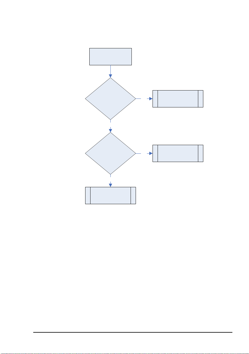
Maintenance and fault finding
BUC fault
diagnosis chart 3
Is
there a
fan fault?
Is
BUC Temp
OK?
See BUC fan fault
diagnosis chart 1.
See BUC fan fault
diagnosis chart 1.
See BUC fault
diagnosis chart 4.
Yes
No
Yes
No
Figure 18: BUC fault diagnosis chart 3
Block Up Converter Systems 6700/6900 series User Guide 89
Page 100

Maintenance and fault finding
Figure 19: BUC fault diagnosis chart 4
BUC fault
diagnosis chart 4
Is PA
OK?
No
Switch off BUC PA
using STO0
command.
Reset BUC using RST
command. Reset
latched faults using
RLF command.
Switch on BUC PA
using STO1
command.
Is
FLT LED
red and PA
showing a
fault?
No
Yes
diagnosis chart 5.
Yes
See BUC fault
BUC faulty.
Refer to Codan.
BUC OK.
Monitor for recurrence
of fault.
90 Block Up Converter Systems 6700/6900 series User Guide
 Loading...