

Page 1

HF Data Modem
3112
HF RADIO COMMUNICATIONS
USER GUIDE
Page 2

No part of this guide may be reproduced, transcribed or
translated into any language or transmitted in any form
whatsoever without the prior written consent of Codan
Limited.
© Copyright 2007 Codan Limited.
Codan part number 15-04147-EN Issue 1, June 2007
HF Express
Easitalk
™
is a trademark of Codan Limited. NGT®,
®
and CALM® are registered trademarks of Codan
Limited. Other brand, product, and company names
mentioned in this document are trademarks or registered
trademarks of their respective holders.
Modem software © Copyright 1995–2004 SPIRIT.
The English version takes precedence over any translated
versions.
Page 3

Table of contents
Introduction
Overview of this guide . . . . . . . . . . . . . . . . . . . . . . . . . . . . . . . . . . . . . . 1
1Overview
The 3112 HF Data Modem . . . . . . . . . . . . . . . . . . . . . . . . . . . . . . . . . . . . . . 4
The front panel . . . . . . . . . . . . . . . . . . . . . . . . . . . . . . . . . . . . . . . . . . . . . . . 9
The rear panel . . . . . . . . . . . . . . . . . . . . . . . . . . . . . . . . . . . . . . . . . . . . . . . 10
2 Installation and setup
Unpacking the equipment . . . . . . . . . . . . . . . . . . . . . . . . . . . . . . . . . . . . . . 14
General . . . . . . . . . . . . . . . . . . . . . . . . . . . . . . . . . . . . . . . . . . . . . . . . . . . . 15
System requirements for a 3112 data station . . . . . . . . . . . . . . . . . . . . . . . 17
Installing the 3112 HF Data Modem . . . . . . . . . . . . . . . . . . . . . . . . . . . . . 19
Connecting the modem to the transceiver. . . . . . . . . . . . . . . . . . . . . . . . . . 21
Connecting the modem to the PC via the Ethernet ports . . . . . . . . . . . . . . 22
Connecting the modem directly to the PC using a crossover
CAT5 Ethernet cable. . . . . . . . . . . . . . . . . . . . . . . . . . . . . . . . . . . . . . . 22
Connecting the modem indirectly to the PC (via an Ethernet
switch) using a straight CAT5 Ethernet cable. . . . . . . . . . . . . . . . . . . . 27
Connecting the modem to the PC via an asynchronous port . . . . . . . . . . . 31
Connecting the modem to the PC via a synchronous port . . . . . . . . . . . . . 38
Testing the installation . . . . . . . . . . . . . . . . . . . . . . . . . . . . . . . . . . . . . . . . 44
Testing communication between two nodes . . . . . . . . . . . . . . . . . . . . . . . . 47
3 Operating the modem
General . . . . . . . . . . . . . . . . . . . . . . . . . . . . . . . . . . . . . . . . . . . . . . . . . . . . 50
Screens . . . . . . . . . . . . . . . . . . . . . . . . . . . . . . . . . . . . . . . . . . . . . . . . . . . . 51
Menu structure . . . . . . . . . . . . . . . . . . . . . . . . . . . . . . . . . . . . . . . . . . . . . . 54
Using the navigation buttons . . . . . . . . . . . . . . . . . . . . . . . . . . . . . . . . . . . 55
Operating the modem using controlling software. . . . . . . . . . . . . . . . . . . . 58
Selecting a waveform . . . . . . . . . . . . . . . . . . . . . . . . . . . . . . . . . . . . . . . . . 59
HF Data Modem 3112 User Guide i
Page 4

Table of contents
Saving a user profile . . . . . . . . . . . . . . . . . . . . . . . . . . . . . . . . . . . . . . . . . . 63
Loading a profile . . . . . . . . . . . . . . . . . . . . . . . . . . . . . . . . . . . . . . . . . . . . . 64
Resetting to factory defaults . . . . . . . . . . . . . . . . . . . . . . . . . . . . . . . . . . . . 65
Using the on-board help in the modem . . . . . . . . . . . . . . . . . . . . . . . . . . . . 66
Appendix A—Menu structures for waveforms
MIL-STD-188-110A . . . . . . . . . . . . . . . . . . . . . . . . . . . . . . . . . . . . . . . . . . 68
MIL-STD-188-110B . . . . . . . . . . . . . . . . . . . . . . . . . . . . . . . . . . . . . . . . . . 69
STANAG 4539 . . . . . . . . . . . . . . . . . . . . . . . . . . . . . . . . . . . . . . . . . . . . . . 71
STANAG 4415 . . . . . . . . . . . . . . . . . . . . . . . . . . . . . . . . . . . . . . . . . . . . . . 73
Appendix B—Connectors
Transceiver Control connector . . . . . . . . . . . . . . . . . . . . . . . . . . . . . . . . . . 76
Modem Control connector. . . . . . . . . . . . . . . . . . . . . . . . . . . . . . . . . . . . . . 77
Transceiver connector . . . . . . . . . . . . . . . . . . . . . . . . . . . . . . . . . . . . . . . . . 78
Sync/Async Data connector. . . . . . . . . . . . . . . . . . . . . . . . . . . . . . . . . . . . . 80
Ethernet connector . . . . . . . . . . . . . . . . . . . . . . . . . . . . . . . . . . . . . . . . . . . . 82
Appendix C—Specifications
Appendix D—Factory-default settings
Appendix E—Compliance
Introduction . . . . . . . . . . . . . . . . . . . . . . . . . . . . . . . . . . . . . . . . . . . . . . . . . 88
European R&TTE Directive . . . . . . . . . . . . . . . . . . . . . . . . . . . . . . . . . . . . 89
Electromagnetic compatibility and safety notices . . . . . . . . . . . . . . . . . . . .90
FCC compliance . . . . . . . . . . . . . . . . . . . . . . . . . . . . . . . . . . . . . . . . . . . . . 92
ii HF Data Modem 3112 User Guide
Page 5

Appendix F—Definitions
Standards and icons . . . . . . . . . . . . . . . . . . . . . . . . . . . . . . . . . . . . . . . . . . 93
Acronyms and abbreviations . . . . . . . . . . . . . . . . . . . . . . . . . . . . . . . . . . . 94
Glossary . . . . . . . . . . . . . . . . . . . . . . . . . . . . . . . . . . . . . . . . . . . . . . . . . . . 96
Units . . . . . . . . . . . . . . . . . . . . . . . . . . . . . . . . . . . . . . . . . . . . . . . . . . . . . . 98
Unit multipliers . . . . . . . . . . . . . . . . . . . . . . . . . . . . . . . . . . . . . . . . . . . . . . 98
About this issue. . . . . . . . . . . . . . . . . . . . . . . . . . . . . . . . . . . . . . . . . . . . . . 99
Table of contents
HF Data Modem 3112 User Guide iii
Page 6

Table of contents
This page has been left blank intentionally.
iv HF Data Modem 3112 User Guide
Page 7

List of figures
Figure 1: Typical system layout. . . . . . . . . . . . . . . . . . . . . . . . . . . . 5
Figure 2: Typical system layout using the Codan STANAG
5066 Stack with HF Express . . . . . . . . . . . . . . . . . . . . . . 6
Figure 3: Front panel of the 3112. . . . . . . . . . . . . . . . . . . . . . . . . . . 9
Figure 4: Rear panel of the 3112 . . . . . . . . . . . . . . . . . . . . . . . . . . 10
Figure 5: Connecting the modem directly to the PC via the
Ethernet ports . . . . . . . . . . . . . . . . . . . . . . . . . . . . . . . . . 23
Figure 6: Connecting the modem indirectly to the PC via an
Ethernet switch with DHCP server. . . . . . . . . . . . . . . . . 28
Figure 7: Connecting the modem to the PC via an
asynchronous port. . . . . . . . . . . . . . . . . . . . . . . . . . . . . . 32
Figure 8: Connecting the modem to the PC via a
synchronous port . . . . . . . . . . . . . . . . . . . . . . . . . . . . . . 39
Figure 9: Layout of the status screen . . . . . . . . . . . . . . . . . . . . . . . 51
Figure 10: Layout of a menu screen. . . . . . . . . . . . . . . . . . . . . . . . . 52
Figure 11: Screen during data transmission. . . . . . . . . . . . . . . . . . . 52
Figure 12: Screen during data reception . . . . . . . . . . . . . . . . . . . . . 53
Figure 13: Top-level menu structure for the modem . . . . . . . . . . . . 54
Figure 14: Menu structure for MIL-STD-188-110A
waveform . . . . . . . . . . . . . . . . . . . . . . . . . . . . . . . . . . . . 68
Figure 15: Menu structure for MIL-STD-188-110B
waveform (serial tone) . . . . . . . . . . . . . . . . . . . . . . . . . . 69
Figure 16: Menu structure for MIL-STD-188-110B
waveform (39Tone) . . . . . . . . . . . . . . . . . . . . . . . . . . . . 70
Figure 17: Menu structure for STANAG 4539 waveform. . . . . . . . 71
Figure 18: Menu structure for STANAG 4415 waveform. . . . . . . . 73
Figure 19: Front view of the Transceiver Control connector. . . . . . 76
Figure 20: Front view of the Modem Control connector . . . . . . . . . 77
Figure 21: Front view of the Transceiver connector . . . . . . . . . . . . 78
Figure 22: Front view of the Sync/Async Data connector. . . . . . . . 80
Figure 23: Front view of the Ethernet connector . . . . . . . . . . . . . . . 82
HF Data Modem 3112 User Guide v
Page 8

List of figures
This page has been left blank intentionally.
vi HF Data Modem 3112 User Guide
Page 9

List of tables
Table 1: Navigation buttons and their function . . . . . . . . . . . . . . 56
Table 2: Available waveforms . . . . . . . . . . . . . . . . . . . . . . . . . . . 60
Table 3: Typical data rates, SNR and channel quality . . . . . . . . . 61
Table 4: Waveform, data rate and interleaver
relationships . . . . . . . . . . . . . . . . . . . . . . . . . . . . . . . . . . 61
Table 5: Pinouts for the Transceiver Control connector. . . . . . . . 76
Table 6: Pinouts for the Modem Control connector . . . . . . . . . . . 77
Table 7: Pinouts for the Transceiver connector . . . . . . . . . . . . . . 78
Table 8: Pinouts for the Sync/Async Data
connector . . . . . . . . . . . . . . . . . . . . . . . . . . . . . . . . . . . . 80
Table 9: Pinouts for the Ethernet connector . . . . . . . . . . . . . . . . . 82
Table 10: Specifications . . . . . . . . . . . . . . . . . . . . . . . . . . . . . . . . . 83
Table 11: Factory-default settings for the modem . . . . . . . . . . . . . 85
Table 12: Factory-default settings for the STANAG 4539
waveform . . . . . . . . . . . . . . . . . . . . . . . . . . . . . . . . . . . . 86
Table 13: Earth symbol. . . . . . . . . . . . . . . . . . . . . . . . . . . . . . . . . . 91
HF Data Modem 3112 User Guide vii
Page 10

List of tables
This page has been left blank intentionally.
viii HF Data Modem 3112 User Guide
Page 11

Introduction
Thank you for purchasing a Codan 3112 HF Data Modem.
With this great product and Codan’s supreme after-sales
support, you can look forward to many years of reliable HF
data communication. Please read this guide thoroughly and
retain it for future reference. There is an index at the end of
this guide to assist you in finding information.
Overview of this guide
This guide is for technicians who install the hardware, and
system administrators who set up how the HF data
communication network interacts with other equipment. It
provides instructions on how to connect and set up a
3112 HF Data Modem with a Codan HF transceiver that is
capable of high-speed data transfer.
This guide assumes that the system administrator is familiar
with setting up HF communication networks for the Codan
NGT series Transceiver and 2110 Manpack Transceiver.
This guide contains the following sections:
Section 1 Overview—provides an overview of the
3112 HF Data Modem, how it is used within a
data communication network, how data flows
through the data system, the waveforms that it
uses, and a brief description of the front and rear
panels
Section 2 Installation and setup—describes how to
connect the Codan 3112 data system together,
how to set up the individual components of the
system, and how to test that the system is
functional
Section 3 Operating the modem—describes the modes of
operation, how to navigate through the menu
system, how to save profiles, and how to access
the on-board help
HF Data Modem 3112 User Guide 1
Page 12

Introduction
Appendix A Menu structures for waveforms—details the
menu structure for each type of waveform that
may be used with the 3112
Appendix B Connectors—details the pinouts of each
connector on the 3112
Appendix C Specifications—provides the common
operational specifications for the 3112
Appendix D Factory-default settings—provides a list of the
default settings for each menu option and the
default waveform
Appendix E Compliance—provides compliance information
and safety notices for your modem
Appendix F Definitions—explains the terms and
abbreviations used in this guide
2 HF Data Modem 3112 User Guide
Page 13

1 Overview
This section contains the following topics:
The 3112 HF Data Modem (4)
The front panel (9)
The rear panel (10)
HF Data Modem 3112 User Guide 3
Page 14

Overview
The 3112 HF Data Modem
The 3112 HF Data Modem provides a robust method of data
communication over an HF path.
A standard Codan HF data station (or node) comprises:
• a Codan HF transceiver that is capable of high-speed
data transfer
• an antenna system
• an appropriate 12 V DC power supply
• a 3112 HF Data Modem
• a PC with terminal software
The 3112 HF Data Modem can operate with a
NOTE
A typical installation uses:
standard data-capable Codan HF transceiver,
however it will operate below the optimum data
transfer rate of 9600 bps.
• an Ethernet connection between the PC and the modem
(see page 22, Connecting the modem to the PC via the
Ethernet ports), or
• three connections between COM and asynchronous/
synchronous ports on the PC and the modem (see
page 31, Connecting the modem to the PC via an
asynchronous port or page 38, Connecting the modem to
the PC via a synchronous port)
4 HF Data Modem 3112 User Guide
Page 15

Terminal
session
to 12 V DC
power supply
3112 HF Data Modem
NGT series Transceiver,
or
2110 Manpack Transceiver
PC
Node 1
to 12 V DC
power supply
3112 HF Data Modem
NGT series Transceiver,
or
2110 Manpack Transceiver
PC
Node 2
to 12 V DC
power supply
3112 HF Data Modem
NGT series Transceiver,
or
2110 Manpack Transceiver
PC
Node 3
Terminal
session
Terminal
session
Set transceiver to a
common channel, and
modem to a common
waveform
Set transceiver to a
common channel, and
modem to a common
waveform
Set transceiver to a
common channel, and
modem to a common
waveform
Figure 1: Typical system layout
Overview
HF Data Modem 3112 User Guide 5
Page 16

Overview
STANAG
5066 Stack
HF Express
STANAG 5066
Stack Control
to 12 V DC
power supply
3112 HF Data Modem
NGT series Transceiver,
or
2110 Manpack Transceiver
PC
Node 1
to 12 V DC
power supply
3112 HF Data Modem
NGT series Transceiver,
or
2110 Manpack Transceiver
PC
Node 2
to 12 V DC
power supply
3112 HF Data Modem
NGT series Transceiver,
or
2110 Manpack Transceiver
PC
Node 3
For example, assign
Node 1 with:
STANAG address 1.1.1.1
For example, assign
Node 2 with:
STANAG address 1.1.1.2
For example, assign
Node 3 with:
STANAG address 1.1.1.3
STANAG
5066 Stack
HF Express
STANAG 5066
Stack Control
STANAG
5066 Stack
HF Express
STANAG 5066
Stack Control
Figure 2: Typical system layout using the Codan STANAG 5066 Stack with HF Express
6 HF Data Modem 3112 User Guide
Page 17

Overview
For ALE use, the modem is assigned a self
address. This is stored in the STANAG 5066
NOTE
Stack against the corresponding STANAG
address for the node. The self address for the
modem should be different from the self address
assigned to the transceiver.
Signal flow
For simple operation, the Codan HF transceivers must be
manually set to the same channel, and the modems must be
manually set to the same waveform. Data is passed from the
terminal session to the modem. It is processed by the modem
then sent to the Codan HF transceiver for transfer via HF to
any transceivers tuned to that frequency. At the receiving
node, the data is passed from the transceiver to the modem,
where it is decoded, ready for presentation at the remote PC.
Figure 1 on page 5 shows a typical layout for a data
communication system.
When the modem operates under the control of the STANAG
5066 Stack, the data may be transferred via an ALE link, or
via two transceivers manually set to the same channel. The
STANAG 5066 Stack requires a STANAG address to be set
for each node. Figure 2 on page 6 shows a typical layout for
an HF data communication network that uses Codan’s
STANAG 5066 Stack and HF Express
™
.
If a modem self address and ALE/CALM network is defined
against the STANAG address for the remote node in the
STANAG 5066 Stack, the Codan HF transceivers establish the
ALE link according to the information provided. If no modem
self address or ALE/CALM network is defined against the
STANAG address for the remote node, the transceivers must
be manually set to the same channel before the data is
transmitted.
The data from the PC is once again prepared by the modem,
sent via HF on the set channel to the specified STANAG
address, then passed to the modem for decoding and
presentation at the remote PC.
HF Data Modem 3112 User Guide 7
Page 18

Overview
The 3112 HF Data Modem indicates on its screen whether it is
transmitting, receiving or idle. For information on screens that
may appear see page 51, Screens.
Power supply
The 3112 HF Data Modem is powered via its connection to
the Codan HF transceiver. When the Codan HF transceiver is
switched on, the connected modem is also switched on.
Alternatively, the 3112 HF Data Modem may be powered via
an external DC power source that provides between 10 and
15 V DC.
Interoperability
The 3112 HF Data Modem supports the following waveforms:
• MIL-STD-188-110A
• MIL-STD-188-110B (serial tone)
• MIL-STD-188-110B (39Tone, parallel)
• STANAG 4539
• STANAG 4415
Operating modes
The modem has two operating modes:
• LOC mode: the modem is under local control
• REM mode: the modem is under remote control by the
Codan STANAG 5066 Stack
8 HF Data Modem 3112 User Guide
Page 19
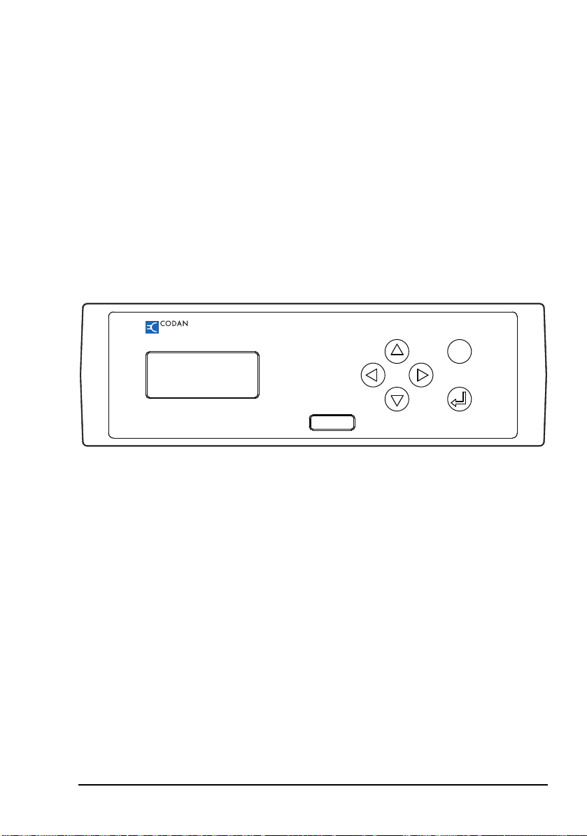
The front panel
3112 HF Data Modem
Made in Australia Serial No.
MENU
The front panel of the 3112 HF Data Modem comprises an
LCD and six navigation buttons. For information on
navigating through the menu structure see page 55, Using the
navigation buttons. For information on the menu structure see
page 54, Menu structure and page 67, Menu structures for
waveforms. For information on screens that are displayed on
the LCD see page 51, Screens.
Figure 3: Front panel of the 3112
Overview
HF Data Modem 3112 User Guide 9
Page 20
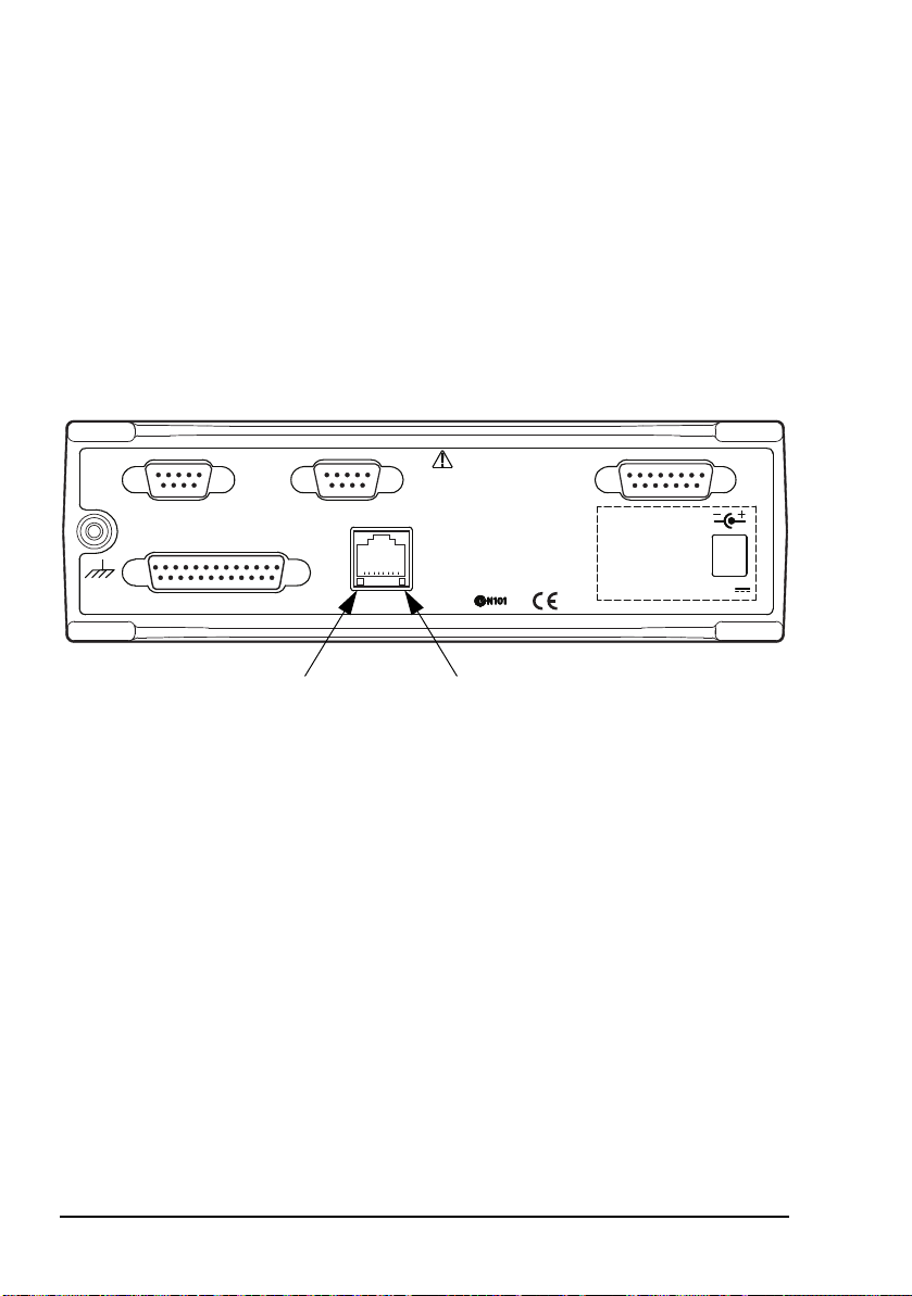
Overview
Transceiver Control Modem Control Transceiver
Sync/Async Data
Ethernet
Refer documentation before
making connections
Separate DC
input not required
when used with
Codan Transceivers
12 V
LAN activity
LED
LAN link
status LED
The rear panel
The rear panel of the 3112 has a standard Ethernet connector
and four D-type connectors.
NOTE
For information on connector pinouts see
page 75, Connectors.
Figure 4: Rear panel of the 3112
The Transceiver Control connector provides a connection
between the modem and a COM port on the PC. This enables
the operator to control the transceiver via a terminal session
using CICS. For information on using these commands see
CICS in the Reference Manual provided with the Codan HF
transceiver.
The Modem Control connector provides a connection
between the modem and a COM port on the PC. This enables
the operator to control the modem using in-built Remote
Control Protocol commands. For information on using these
commands see page 66, Using the on-board help in the
modem.
10 HF Data Modem 3112 User Guide
Page 21

Overview
The Sync/Async Data connector provides a connection
between the modem and the PC by either:
• a COM port (asynchronous mode), or
• a synchronous card (synchronous mode)
The Ethernet connector provides a standard Ethernet
connection between the modem and the PC. This enables the
operator to control the transceiver, modem and data port via
terminal sessions. The data port operates in asynchronous
mode. The connector has two LEDs: one for LAN activity, the
other for the status of the link to the LAN.
The Transceiver connector provides the power, data and
control connection between the modem and the Codan HF
transceiver.
HF Data Modem 3112 User Guide 11
Page 22

Overview
This page has been left blank intentionally.
12 HF Data Modem 3112 User Guide
Page 23

2 Installation and setup
This section contains the following topics:
Unpacking the equipment (14)
General (15)
System requirements for a 3112 data station (17)
Installing the 3112 HF Data Modem (19)
Connecting the modem to the transceiver (21)
Connecting the modem to the PC via the Ethernet ports (22)
Connecting the modem to the PC via an asynchronous
port (31)
Connecting the modem to the PC via a synchronous port (38)
Testing the installation (44)
Testing communication between two nodes (47)
HF Data Modem 3112 User Guide 13
Page 24

Installation and setup
Unpacking the equipment
On receiving your 3112 HF Data Modem, check the contents
against the packing list. Make sure that all equipment itemised
on the packing list is present before you start installing the
modem into your HF data communication network.
Open the packing case and examine the contents for signs of
damage. If you notice any damage, contact Codan
immediately for an RMA. Failure to contact Codan before
returning the unit may result in any warranty being void.
We recommend that the equipment is installed by qualified
and experienced personnel, to the relevant standards and
approvals.
14 HF Data Modem 3112 User Guide
Page 25

General
Installation and setup
These installation instructions assume the following:
• The Codan HF transceiver, which is capable of highspeed data transfer, has an appropriate power supply and
antenna system connected, and all modules within the
transceiver system are functioning correctly.
• The HF data communication network is planned.
• If the modem and PC at a node are connected via their
Ethernet ports and are not using DHCP, there must be an
IP address assigned to both the modem and the PC.
These IP addresses must use the same subnet.
IP addresses must be assigned by a system
NOTE
If the HF data communication network is to be controlled
entirely by the Codan STANAG 5066 Stack, then:
administrator who is knowledgable in IP
addressing and networking.
• Each node in the HF data communication network must
have a STANAG address assigned to it.
• For ALE operation:
• The Codan HF transceiver must contain an
ALE/CALM network with channels and an appropriate
self address.
• The modem at each node must be assigned a self
address that is different from the self address for the
transceiver. The self address of the modem must be
assigned to the STANAG address for the node, along
with the name of the ALE/CALM network.
For information on setting up your HF data
NOTE
HF Data Modem 3112 User Guide 15
communication network for ALE operation
see the STANAG 5066 Stack Help.
Page 26

Installation and setup
Once installed and set up as required for the particular
configuration, you should not need to alter any of the settings
for the modem.
NOTE
Factory-default settings for the modem are
provided on page 85.
16 HF Data Modem 3112 User Guide
Page 27

Installation and setup
System requirements for a 3112 data station
Software requirements for PC
The software requirement for the PC is Windows
XP.
Firmware requirements for transceiver
The firmware requirement for a Codan HF transceiver is
V4.59 or later.
Hardware requirements for PC
®
2000 or
The hardware requirements for the PC are those required to
support Windows
®
2000 or XP, or those stated for the
SeaLevel 5103 synchronous card, if used. This synchronous
card is available from Codan (Codan part number 78-16042).
Hardware requirements for NGT series Transceiver
The hardware requirements for an NGT series Transceiver are:
Description Codan part number
High-speed data 15-10541-000
Fan 15-10469-000
2.7 kHz filter 15-00514-000
If you are upgrading an existing NGT
Transceiver for operation with a 3112 HF Data
NOTE
Modem, you should confirm that is has:
• RF/IF PCB 07-01961-07 (or later), and
• Filter & Control PCB 07-01967-05 (or later)
HF Data Modem 3112 User Guide 17
Page 28

Installation and setup
NGT AR, SR and ASR Transceivers with build
standard Z and NGT SRx Transceivers with
NOTE
build standard E have hardware that is
compatible for operation with the 3112 HF Data
Modem. The build standard is indicated by the
fifth digit from the right in the serial number.
Hardware requirements for 2110 Manpack Transceiver
The hardware requirements for a 2110 Manpack Transceiver
are:
Description Codan part number
2.7 kHz filter 15-10529-000
If you are upgrading an existing 2110 Manpack
NOTE
Transceiver for operation with a 3112 HF Data
Modem, you should confirm that is has
RF/IF PCB 07-02012-04 (or later).
Contact your Codan representative for the build
NOTE
standard that reflects compatible hardware in
the 2110 Manpack Transceiver.
External DC power supply
The 3112 HF Data Modem may be operated using an external
DC power supply if the correct power is not supplied from the
third-party transceiver. The power supply must operate
between 10 and 15 V DC.
18 HF Data Modem 3112 User Guide
Page 29

Installing the 3112 HF Data Modem
The 3112 HF Data Modem is connected from the
Transceiver connector on the modem to the 15-way or
19-way connector on the Codan HF transceiver (see page 21,
Connecting the modem to the transceiver).
The 3112 HF Data Modem may be connected to a PC in one
of three different configurations:
• via Ethernet ports (see page 22, Connecting the modem
to the PC via the Ethernet ports)
• via an asynchronous port (see page 31, Connecting the
modem to the PC via an asynchronous port)
• via a synchronous port (see page 38, Connecting the
modem to the PC via a synchronous port)
Use USB-to-serial-port cables to create COM
NOTE
ports if your PC only has USB ports. This cable
may be ordered from Codan (Codan part
number 78-01031).
Installation and setup
The connection diagrams in this guide show the 3112 HF Data
Modem connected to an NGT series Transceiver. If you are
using a 2110 Manpack Transceiver, you can connect the
modem directly to the 19-way connector on the front panel of
the transceiver, or via the 15-way connector on the Interface
Adaptor.
HF Data Modem 3112 User Guide 19
Page 30

Installation and setup
The following process should be followed during installation:
• install and set up the Codan HF transceiver, antenna and
power supply (see the documentation provided with the
transceiver)
• connect the transceiver to the modem
• connect the modem to the PC
• test the installation
• test the node-to-node communication
• install and set up the Codan STANAG 5066 Stack, if
required
• install and set up HF Express
™
, if required
By default, the backlighting for the LCD on the
modem switches off 10 seconds after a button
NOTE
has been pressed. During initial setup, it may be
useful to set the backlighting to ON (see
Figure 13 on page 54 and page 57, Accessing
and changing a value).
20 HF Data Modem 3112 User Guide
Page 31

Installation and setup
Connecting the modem to the transceiver
To connect the modem to the transceiver:
1 Ensure the transceiver is switched off.
1 Do one of the following:
• connect cable 08-06356-00x between the
Transceiver connector on the modem and the 15-way
connector on the NGT series Transceiver or Interface
Adaptor (2110 only)
• connect cable 08-06786-00x between the
Transceiver connector on the modem and the 19-way
connector on the front panel of the 2110 Manpack
Transceiver
You should only use the cables provided
NOTE
with the 3112 HF Data Modem to ensure
optimal performance.
1 Switch on the transceiver.
1 Access the Control List in the transceiver.
1 Do one of the following:
• In the NGT series Transceiver, set the RS232 15way
Mode entry to Modem Hold AGC, and the RS232
15way Speed entry to 9600.
• In the 2110 Manpack Transceiver, set the RS232 Mode
entry to Modem Slow AGC, and the RS232 Speed
entry to 9600.
1 Switch off the transceiver.
HF Data Modem 3112 User Guide 21
Page 32

Installation and setup
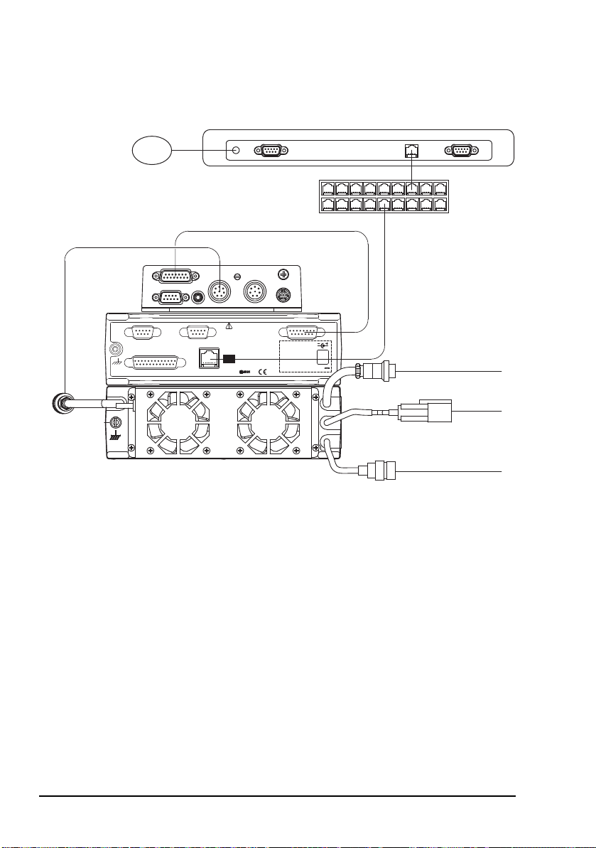
Connecting the modem to the PC via the Ethernet ports
The Ethernet connection between the modem and the PC can
be made in two ways:
• directly, using a crossover CAT5 Ethernet cable (see
Figure 5 on page 23)
• indirectly, via an Ethernet switch, using a straight CAT5
Ethernet cable (see Figure 6 on page 28)
A ferrite bead (Codan part number
NOTE
Connecting the modem directly to the PC using a crossover CAT5 Ethernet cable
39-79150-080) must be attached to the Ethernet
cable as close as possible to the Ethernet
connector on the modem.
This type of connection requires you to:
• connect the modem to the PC
• disable DHCP in the modem
• enter an IP address and subnet mask for the modem
• enter an IP address and subnet mask for the PC
• check the asynchronous Speed Mode setting in the
modem
22 HF Data Modem 3112 User Guide
Page 33
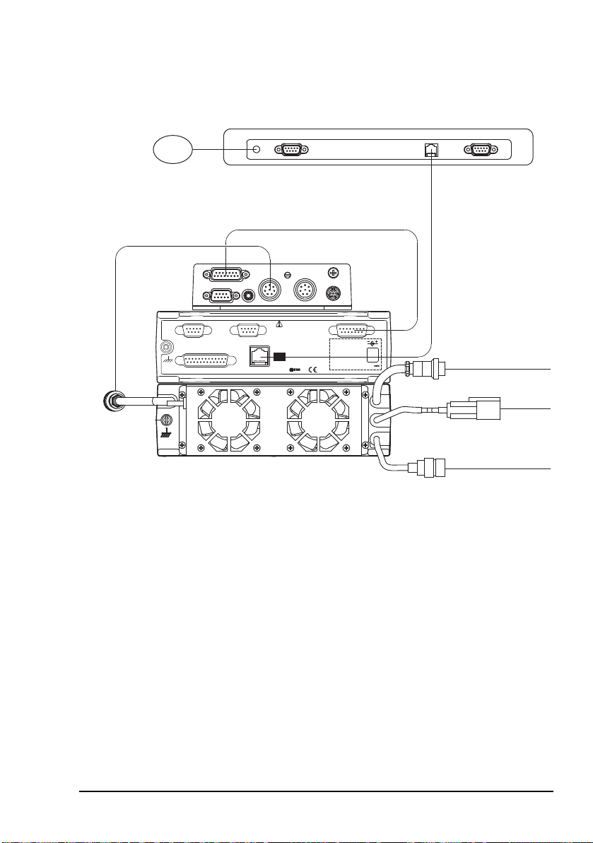
Installation and setup
Transceiver Control Modem Control Transceiver
Sync/Async Data
Ethernet
Refer documentation before
making connections
Separate DC
input not required
when used with
Codan Transceivers
12 V
to
antenna
to power
supply
Power
in
08-06356-00x
crossover Ethernet cable
67-90800 (2 m)
67-90801 (10 m)
NOTE
Cable 08-06786-00x is used to connect the modem
to the 19-way connector on a 2110 Manpack Transceiver
to antenna control
(if required)
Figure 5: Connecting the modem directly to the PC via the Ethernet ports
NOTE
For information on connecting the modem to
the transceiver see page 21, Connecting the
modem to the transceiver.
HF Data Modem 3112 User Guide 23
Page 34

Installation and setup
Connecting the modem directly to the PC
To connect the modem to the PC:
1 Connect a crossover CAT5 Ethernet cable between the
Ethernet connector on the modem and the Ethernet
connector on the PC.
The following crossover CAT5 Ethernet
NOTE
cables are available from Codan:
• 2 m cable (67-90800)
• 10 m cable (67-90801)
1 Attach the ferrite bead (Codan part number
39-79150-080) to the Ethernet cable as close as possible
to the Ethernet connector on the modem.
1 Switch on the PC and the transceiver, then wait until the
modem has initialised.
Disabling DHCP in the modem
NOTE DHCP is disabled by default.
To disable DHCP:
1 On the front panel of the modem, press MENU.
1 Press repeatedly to scroll down through the menu
options until Remote Control is highlighted.
1 Press to enter the menu, press to enter the DHCP
setting, then use to set DHCP to OFF.
1 Press to save the setting.
24 HF Data Modem 3112 User Guide
Page 35
Installation and setup
MENU
Setting an IP address and subnet mask in the modem
The non-internet default IP address for the
NOTE
To enter an IP address:
modem is 192.168.3.112.
The default subnet mask for the modem is
255.255.255.0.
1 On the front panel of the modem, press MENU.
1 Press repeatedly to scroll down through the menu
options until Remote Control is highlighted.
1 Press to enter the menu.
1 Press to scroll down through the menu options until
IP Address is highlighted.
1 Press to enter the setting, press to scroll across the
value, and use and to alter each highlighted value
as required.
1 Press to save the IP address.
1 Press to scroll down through the menu options until
Subnet Mask is highlighted.
1 Press to enter the setting, press to scroll across the
value, and use and to alter each highlighted value
as required.
1 Press to save the subnet mask.
1 Save the profile (see page 63, Saving a user profile).
1 Reset the modem by pressing , and
simultaneously.
HF Data Modem 3112 User Guide 25
Page 36

Installation and setup
Setting an IP address and subnet mask in the PC
The options that you see depend upon the
version of Microsoft Windows
NOTE
To set up the PC for operation with the modem:
installed (Windows
For more information on this topic see the online help provided for Windows
®
XP is described below).
®
that you have
®
.
1 In Windows, from the Start menu, select Control
Panel—Network Connections.
1 Double-click on Local Area Connection.
1 Select the network that you want to use from the list.
1 Click on Properties.
1 Scroll through the listed components used by this
connection, select Internet Protocol (TCP/IP), then
click on Properties.
1 Select Use the following IP address, then enter an
IP address that uses the same subnet as the modem, for
example, 192.168.3.1.
1 Enter an appropriate subnet mask, for example,
255.255.255.0.
1 Click on OK.
26 HF Data Modem 3112 User Guide
Page 37

Installation and setup
Checking the asynchronous settings in the modem
To check the asynchronous settings:
1 On the front panel of the modem, press MENU.
1 Press repeatedly to scroll down through the menu
options until Async Settings is highlighted.
1 Press to enter the menu, press to enter the Speed
Mode setting, then use to set the mode to
HIGHSPEED.
1 Press to save the setting.
1 Save the profile (see page 63, Saving a user profile).
Connecting the modem indirectly to the PC (via an Ethernet switch) using a straight CAT5 Ethernet cable
This type of connection requires you to:
• connect the modem to the PC via an Ethernet switch
• enable DHCP in the modem
• set up the PC to automatically obtain an IP address
• check the asynchronous Speed Mode setting in the
modem
HF Data Modem 3112 User Guide 27
Page 38
Installation and setup
Transceiver Control Modem Control Transceiver
Sync/Async Data
Ethernet
Refer documentation before
making connections
Separate DC
input not required
when used with
Codan Transceivers
12 V
to
antenna
to antenna control
(if required)
to power
supply
Power
in
08-06356-00x
straight Ethernet cable
67-90802 (2 m)
67-90803 (10 m)
NOTE
Cable 08-06786-00x is used to connect the modem
to the 19-way connector on a 2110 Manpack Transceiver
Ethernet switch
with DHCP server
Figure 6: Connecting the modem indirectly to the PC via an Ethernet switch with DHCP server
NOTE
For information on connecting the modem to
the transceiver see page 21, Connecting the
modem to the transceiver.
28 HF Data Modem 3112 User Guide
Page 39

Installation and setup
MENU
Connecting the modem indirectly to the PC via an Ethernet switch
To connect the modem to the PC via an Ethernet switch:
1 Connect a straight CAT5 Ethernet cable between the
Ethernet connector on the modem and an Ethernet
network point.
1 Connect a straight CAT5 Ethernet cable between the
Ethernet port on a PC and an Ethernet network point.
The following straight CAT5 Ethernet
NOTE
cables are available from Codan:
• 2 m cable (67-90802)
• 10 m cable (67-90803)
1 Attach the ferrite bead (Codan part number
39-79150-080) to the Ethernet cable as close as possible
to the Ethernet connector on the modem.
1 Switch on the PC and the transceiver, then wait until the
modem has initialised.
Enabling DHCP in the modem
NOTE DHCP is disabled by default.
To enable DHCP:
1 On the front panel of the modem, press MENU.
1 Press repeatedly to scroll down through the menu
options until Remote Control is highlighted.
1 Press to enter the menu, press to enter the DHCP
setting, then use to set DHCP to ON.
1 Press to save the setting.
1 Save the profile (see page 63, Saving a user profile).
1 Reset the modem by pressing , and
simultaneously.
HF Data Modem 3112 User Guide 29
Page 40

Installation and setup
Setting up the PC to automatically obtain an IP address
The options that you see depend upon the
version of Microsoft Windows
NOTE
To set up the PC for operation with the modem:
installed (Windows
For more information on this topic see the online help provided for Windows
®
XP is described below).
®
that you have
®
.
1 In Windows, from the Start menu, select Control
Panel—Network Connections.
1 Double-click on Local Area Connection.
1 Select the network that you want to use from the list.
1 Click on Properties.
1 Scroll through the listed components used by this
connection, select Internet Protocol (TCP/IP), then
click on Properties.
1 Select Obtain an IP address automatically.
1 Click on OK.
Checking the asynchronous settings in the modem
To check the asynchronous settings:
1 On the front panel of the modem, press MENU.
1 Press repeatedly to scroll down through the menu
options until Async Settings is highlighted.
1 Press to enter the menu, press to enter the Speed
Mode setting, then use to set the mode to
HIGHSPEED.
1 Press to save the setting.
1 Save the profile (see page 63, Saving a user profile).
30 HF Data Modem 3112 User Guide
Page 41

Installation and setup
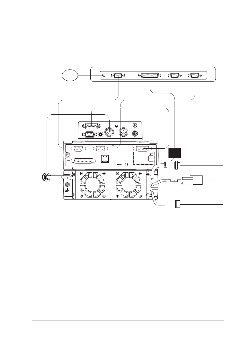
Connecting the modem to the PC via an asynchronous port
This type of connection requires you to:
• connect the modem to the PC
• set up the modem for asynchronous operation
• define the COM ports
Figure 7 shows the connections required between the modem
and the PC when they are connected via an asynchronous port.
Permanent connections between the Transceiver Control
and Modem Control connectors on the modem to the PC are
only required for control of these units when the Codan
STANAG 5066 Stack is installed in the PC.
HF Data Modem 3112 User Guide 31
Page 42

Installation and setup
Transceiver Control Modem Control Transceiver
Sync/Async Data
Ethernet
Refer documentation before
making connections
Separate DC
input not required
when used with
Codan Transceivers
12 V
to
antenna
to power
supply
Power
in
08-06356-00x
08-06034-00x
serial cable serial cable
NOTE
Cable 08-06786-00x is used to connect the modem
to the 19-way connector on a 2110 Manpack Transceiver
08-06360-00x 08-06360-00x
to antenna control
(if required)
Figure 7: Connecting the modem to the PC via an asynchronous port
For information on connecting the modem to
NOTE
the transceiver see page 21, Connecting the
modem to the transceiver.
32 HF Data Modem 3112 User Guide
Page 43

Installation and setup
Connecting the modem to the PC
To connect the modem to the PC:
1 Connect the Sync/Async Data connector on the
modem to a COM port on the PC using the 25-way to
9-way cable (Codan part number 08-06034-00x).
1 If you want to control the transceiver via the Codan
STANAG 5066 Stack or a terminal session, connect the
Transceiver Control connector on the modem to a
COM port on the PC using a 9-way to 9-way serial cable
(Codan part number 08-06360-00x).
1 If you want to control the modem via the Codan
STANAG 5066 Stack or a terminal session, connect the
Modem Control connector on the modem to a COM
port on the PC using a 9-way to 9-way serial cable
(Codan part number 08-06360-00x).
Setting up the modem for asynchronous operation
To set up the modem to operate asynchronously:
1 On the front panel of the modem, press MENU.
1 Press repeatedly to scroll down through the menu
options until Data Port Mode is highlighted.
1 Press to enter the setting, then use to set the Data
Port Mode to ASYNC.
1 Press to save the setting.
1 Press repeatedly to scroll down through the menu
options until Async Settings is highlighted.
HF Data Modem 3112 User Guide 33
Page 44

Installation and setup
1 Press to enter the menu, then use to set any of the
following settings as required, then press .
Async Setting Description
Speed Mode Sets whether the data transmission
is:
• NORMAL (with start/stop
framing; recommended for
loopmode testing of the modem)
• HIGHSPEED (without
start/stop framing;
recommended for normal
operation)
Data Bits Sets the number of data bits per
character for the interface
Data bits may be set in the range
5–8, typically 8
The value set here should match
the value set for the COM port on
the PC
Parity Sets whether odd, even or no
parity is used
The value set here should match
the value set for the COM port on
the PC
Stop Bits Sets whether 1 or 2 stop bits are
transmitted at the end of each
character
The value set here should match
the value set for the COM port on
the PC
34 HF Data Modem 3112 User Guide
Page 45

Installation and setup
Async Setting Description
Data Flow Ctrl Sets whether the flow control is:
• NONE
• CTS (hardware)
The value set here should match
the value set for the COM port on
the PC
Data Rate Sets the data interface baud rate in
bits per second from common
baud rates in the range 75 to
115200 bps
The value set here should be at
least twice the maximum transmit
and receive data rates in the
modem, for example, set this to
19200 bps to use 9 600 bps on air
Polarity Sets whether the polarity is:
• NORMAL (space is positive,
mark is negative)
• INVERTED (space is negative,
mark is positive)
RTS Mode Sets whether RTS signal
transitions are:
• IGNORED (modem transmitter
is activated when data is
provided from DTE)
• TXCTRL (RTS signal controls
the modem transmitter)
1 If you have made any changes from the default profile,
save the profile (see page 63, Saving a user profile).
HF Data Modem 3112 User Guide 35
Page 46

Installation and setup
Defining the COM ports
To define the COM ports:
1 Open three terminal-emulation sessions.
1 Assign a terminal-emulation session to each of the COM
ports used by the modem. Use the following
communication settings to determine which COM port
on the PC is used by which connector on the modem.
Connector on
modem
Transceiver
Control
Modem
Control
Async Data Data rate: at least twice the
COM port settings Typical command/response
Data rate: 9600 bps
Data bits: 8
Parity: Even
Stop bits: 1
Flow control: None
Data rate: 9600 bps
Data bits: 8
Parity: Even
Stop bits: 1
Flow control: None
maximum transmit and
receive data rates set in the
modem
Data bits: same as modem
Parity: same as modem
Stop bits: same as modem
Flow control: same as
modem
Command: ver
Response: CICS: V3.20
Command: report?
Response: REPORT = OFF
OK
See page 47, Testing communication
between two nodes
1 Name each terminal-emulation session with an
appropriate name that reflects its use, then save the
session.
If you are using a Windows
NOTE
36 HF Data Modem 3112 User Guide
system, confirm that your settings are
correct before saving the session.
®
XP operating
Page 47

NOTE
Installation and setup
If you intend to use the Codan STANAG
5066 Stack, you must record which COM
port is assigned to each port on the modem,
as this information must be entered during
installation of the stack.
HF Data Modem 3112 User Guide 37
Page 48

Installation and setup
Connecting the modem to the PC via a synchronous port
This type of connection requires you to:
• connect the modem to the PC
• set up the modem for synchronous operation
• define the COM ports
• set up the synchronous card for operation with the
modem
Figure 8 shows the connection required between the modem
and the PC when they are connected via a synchronous port.
Permanent connections between the Transceiver Control
and Modem Control connectors on the modem to the PC are
only required for control of these units when the Codan
STANAG 5066 Stack is installed in the PC.
38 HF Data Modem 3112 User Guide
Page 49
Transceiver Control Modem Control Transceiver
Sync/Async Data
Ethernet
Refer documentation before
making connections
Separate DC
input not required
when used with
Codan Transceivers
12 V
to
antenna
to power
supply
Power
in
08-06356-00x
08-06361-00x
serial cable serial cable
NOTE
Cable 08-06786-00x is used to connect the modem
to the 19-way connector on a 2110 Manpack Transceiver
08-06360-00x 08-06360-00x
SeaLevel 5103 card,
synchronous
serial port
cryptographic
unit (optional)
to antenna control
(if required)
Installation and setup
Figure 8: Connecting the modem to the PC via a synchronous port
For information on connecting the modem to
NOTE
HF Data Modem 3112 User Guide 39
the transceiver see page 21, Connecting the
modem to the transceiver.
Page 50

Installation and setup
Connecting the modem to the PC
To connect the modem to the PC:
1 Connect the Sync/Async Data connector on the
modem to the synchronous port on the PC using the
25-way to 25-way cable (Codan part number
08-06361-00x).
1 If you want to control the transceiver via the Codan
STANAG 5066 Stack or a terminal session, connect the
Transceiver Control connector on the modem to a
COM port on the PC using a 9-way to 9-way serial cable
(Codan part number 08-06360-00x).
1 If you want to control the modem via the Codan
STANAG 5066 Stack or a terminal session, connect the
Modem Control connector on the modem to a COM
port on the PC using a 9-way to 9-way serial cable
(Codan part number 08-06360-00x).
Setting up the modem for synchronous operation
To set up the modem to operate synchronously:
1 On the front panel of the modem, press MENU.
1 Press repeatedly to scroll down through the menu
options until Data Port Mode is highlighted.
1 Press to enter the setting, then use to set the Data
Port Mode to SYNC.
1 Press to save the setting.
1 Press repeatedly to scroll down through the menu
options until Sync Settings is highlighted.
40 HF Data Modem 3112 User Guide
Page 51

Installation and setup
1 Press to enter the menu, then use to set any of the
following settings as required, then press .
Sync Setting Description
Tx Clock Sets whether the source for the Tx
Clock comes from:
• INPUT (the modem
synchronises with the clock
generated by the DTE)
• OUTPUT (the DTE
synchronises with the clock
generated by the modem)
Polarity Sets whether the polarity is:
• NORMAL (space is positive,
mark is negative)
• INVERTED (space is negative,
mark is positive)
1 If you have made any changes from the default profile,
save the profile (see page 63, Saving a user profile).
HF Data Modem 3112 User Guide 41
Page 52

Installation and setup
Defining the COM ports
To define the COM ports:
1 Open two terminal-emulation sessions.
1 Assign a terminal-emulation session to each of the COM
ports used by the modem. Use the following
communication settings to determine which COM port
on the PC is used by which connector on the modem.
Connector COM port settings Typical command/response
Transceiver
Control
Modem
Control
Data rate: 9600 bps
Data bits: 8
Parity: Even
Stop bits: 1
Flow control: None
Data rate: 9600 bps
Data bits: 8
Parity: Even
Stop bits: 1
Flow control: None
Command: ver
Response: CICS: V3.20
Command: report?
Response: REPORT = OFF
OK
1 Name each terminal-emulation session with an
appropriate name that reflects its use, then save the
session.
If you are using a Windows
NOTE
NOTE
system, confirm that your settings are
correct before saving the session.
If you are using the Codan STANAG 5066
Stack, you must record which COM port is
assigned to each port on the modem, as this
information must be entered during
installation of the stack.
®
XP operating
42 HF Data Modem 3112 User Guide
Page 53

Installation and setup
Setting up the synchronous card for operation with the modem
The installation CD provided with the synchronous card
automatically sets up the card for operation with the modem.
HF Data Modem 3112 User Guide 43
Page 54

Installation and setup
Testing the installation
If you are testing an Ethernet installation, you
need to know the IP address of the modem in
NOTE
NOTE
To test that the modem and PC are communicating:
order to test the installation. See Figure 13 on
page 54 for the location of the IP address setting
in the menu structure.
The terminal-emulation sessions using COM
ports described below were defined during
installation (see page 36 or page 42, Defining
the COM ports).
1 Switch on the PC and the transceiver, then wait until the
modem has initialised.
1 Do one of the following:
• For an Ethernet installation, start a terminal-emulation
session using a TCP/IP connection for each of the
following:
Port Enter...
Data Host address: <IP address of modem>,
for example, 192.168.3.112
Port number: <base port of modem>, for
example, 50000
Modem
control
NOTE
44 HF Data Modem 3112 User Guide
Host address: <IP address of modem>,
for example, 192.168.3.112
Port number: <base port of modem + 2>,
for example, 50002
The host address listed above is the default
IP address for the modem. The port
number listed above is the default base port
of the modem.
Page 55

Installation and setup
• For an asynchronous COM port installation, start the
following terminal sessions:
Connector Terminal
Sync/Async Data Any terminal-emulation program
Modem Control Any terminal-emulation program
• For a synchronous port installation, start the following
terminal sessions:
Connector Terminal
Sync/Async Data WinSSD
Modem Control Any terminal-emulation program
Save any new setup for a terminal session
NOTE
with an appropriate name that reflects its
use.
1 In the modem control session, type:
report off
tcvr duplex full
loopmode audio
async mode normal
1 If you are testing a synchronous port installation, use the
terminal software supplied with the synchronous card
(WinSSD) to set up the synchronous port to match the
synchronous settings in your modem.
If the synchronous setting in the modem
for Tx Clock is set to INPUT (that is, the
NOTE
HF Data Modem 3112 User Guide 45
clock is supplied by the modem), the
selected clock bit rate for the synchronous
card must match the currently selected
transmit data rate of the modem.
Page 56

Installation and setup
LOC
TX 4539 300 S
RX 4539 300 S
PTT SNR 14 dB
MENU
1 In the data session, type some test text.
The text that you type is passed via the modem and
appears in the terminal session.
The LCD on the modem shows that the modem is
transmitting and receiving simultaneously. For example:
1 Reset the modem by pressing , and
simultaneously.
The modem is installed correctly.
46 HF Data Modem 3112 User Guide
Page 57

Installation and setup
Testing communication between two nodes
The modem must be set to half duplex and no
loopmode. These can be set via the front panel
of the modem (see page 55, Using the
NOTE
To test communication between two nodes:
navigation buttons and Figure 13 on page 54) or
via a terminal-emulation session on the modem
control port using tcvr duplex half and
loopmode none commands.
1 Ensure that the transceiver and modem at each node are
switched on, that the modems are using a common
waveform, and that the transceivers are set to a common
channel.
1 Do one of the following:
• If your modem and PC are connected via the Ethernet
ports, open the terminal-emulation session on the data
port (for help see page 44, Testing the installation).
• If your modem and PC are connected via an
asynchronous COM port, open the terminal-emulation
session on the COM port connected to the
Sync/Async Data connector (for help see page 44,
Testing the installation).
• If your modem and PC are connected via a
synchronous port, open the WinSSD terminal session
on the synchronous port.
1 In the terminal-emulation/WinSSD session for the data
port, type some text.
This text appears in the terminal-emulation/WinSSD
session for the data port at the remote node.
HF Data Modem 3112 User Guide 47
Page 58

Installation and setup
REM
TX 4539 300 S
RX 4539 AUTO
PTT
REM
TX 4539 300 S
RX 4539 300 S
SNR 10 dB
The LCD on the modem at the local node indicates that
the modem is under remote control and is transmitting.
The LCD on the modem at the remote node indicates that
the modem is under remote control and is receiving.
The modems transmit and receive.
1 Repeat this test from the other node.
48 HF Data Modem 3112 User Guide
Page 59

3 Operating the modem
This section contains the following topics:
General (50)
Screens (51)
Menu structure (54)
Using the navigation buttons (55)
Operating the modem using controlling software (58)
Selecting a waveform (59)
Saving a user profile (63)
Loading a profile (64)
Resetting to factory defaults (65)
Using the on-board help in the modem (66)
HF Data Modem 3112 User Guide 49
Page 60

Operating the modem
General
When the 3112 HF Data Modem is used with the Codan
STANAG 5066 Stack, the modem and transceiver operate
automatically under the control of the stack. The stack selects
the most suitable waveform and appropriate settings for the
HF data communication.
When the modem is used without the Codan STANAG 5066
Stack, the transceiver and modem must be operated manually.
The HF link must be established via the handset or front panel
of the Codan HF transceiver. You must select an appropriate
waveform and settings for the HF data communication (see
page 59, Selecting a waveform).
50 HF Data Modem 3112 User Guide
Page 61

Screens
LOC
TX 4539 300 S
RX 4539 AUTO
selected
waveform
data
rate
transmit information
receive information
location of
current control
interleaver
length
Operating the modem
Depending on the current operation of the modem, any one of
the following screens may be active.
The status screen
The status screen is shown when the modem is idle. If a button
on the front panel of the modem has not been pressed for over
30 seconds, the modem returns to the status screen. The
modem is under local control, indicated by LOC at the top
right of the screen. While the modem is under local control,
you can enter the menu structure and make changes to the
setup of the modem.
Figure 9: Layout of the status screen
HF Data Modem 3112 User Guide 51
Page 62

Operating the modem
Waveform
MIL-STD-188-110A
MIL-STD-188-110B
STANAG 4539
active line
menu name
next menu options
REM
TX 4539 300 S
RX 4539 AUTO
PTT
The menu screen
The menu screen is shown when the MENU button is pressed.
It comprises a heading row, followed by a scrolling list of
menu options. A menu option may contain further menu
options, or values that may be changed. For more information
on navigating through the menu structure see page 55, Using
the navigation buttons.
Figure 10: Layout of a menu screen
The transmitting screen
The transmitting screen is shown when the modem transmits
data. PTT is shown at the bottom left of the screen during
transmission. If the modem is under remote control by the
Codan STANAG 5066 Stack, REM is displayed at the top
right of the screen.
You can view, but not change, items in the menu
CAUTION
Figure 11: Screen during data transmission
52 HF Data Modem 3112 User Guide
structure while the modem is under remote
control by the Codan STANAG 5066 Stack.
Page 63

Operating the modem
REM
TX 4539 300 S
RX 4539 300 S
SNR 10 dB
The receiving screen
The receiving screen is shown when the modem receives data.
SNR xx dB is shown at the bottom right of the screen during
reception. If the modem is under remote control by the Codan
STANAG 5066 Stack, REM is displayed at the top right of the
screen. The receive information includes the detected data rate
and interleaver length of the incoming transmission. An SNR
of –10 dB indicates poor link quality. An SNR of 30 dB
indicates excellent link quality.
You can view, but not change, items in the menu
CAUTION
Figure 12: Screen during data reception
structure while the modem is under remote
control by the Codan STANAG 5066 Stack.
HF Data Modem 3112 User Guide 53
Page 64

Operating the modem
Waveform MIL-STD-188-110A
MIL-STD-188-110B
STANAG 4539
STANAG 4415
39Tone
Transceiver ALC Setup Time
Audio Level
PTT Hang Time
PTT Control
Duplex Mode
Sync Settings Tx Clock
Polarity
Async Settings Speed Mode
Data Bits
Parity
Stop Bits
Data Flow Ctrl
Data Rate
Polarity
RTS Mode
Test Loop Mode
Tx Data Source
Remote Control DHCP
MAC Address
Subnet Mask
IP Address
Base Port
User Settings Save Profile
Load Profile
LCD Contrast
Backlight
Data Port Mode SYNC
ASYNC
Gateway Address
See Figure 14 on page 68
See Figure 15 on page 69
See Figure 18 on page 73
See Figure 16 on page 70
See Figure 17 on page 71
Menu structure
NOTE
For details of each waveform see page 67, Menu
structures for waveforms.
Figure 13: Top-level menu structure for the modem
54 HF Data Modem 3112 User Guide
Page 65

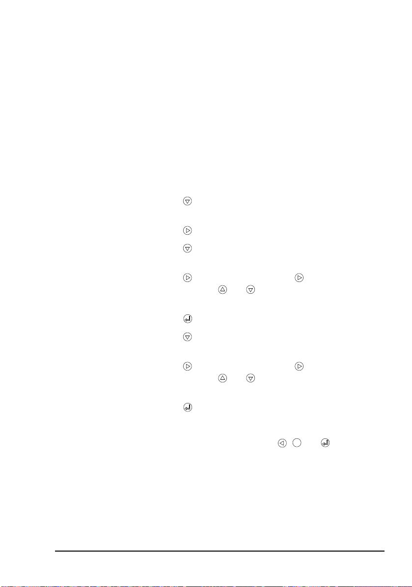
Using the navigation buttons
The navigation buttons
There are six navigation buttons on the front of the
3112 HF Data Modem.
Operating the modem
HF Data Modem 3112 User Guide 55
Page 66

Operating the modem
MENU
Table 1: Navigation buttons and their function
Button Function
One of the following:
• enters the menu structure, or
• if within the menu structure, cancels the current
operation and exits to the top level of the menu,
or
• if at the top level of the menu, shows the status
screen
Saves the currently selected value and exits to the
previous menu level
One of the following:
• scrolls up through the menu options, or
• scrolls up through the list of values available for
the selected menu option or digit
One of the following:
• scrolls down through the menu options, or
• scrolls down through the list of values available
for the selected menu option or digit
One of the following:
• moves out of a submenu to the previous level
without saving the current value, or
• scrolls to the previous digit
One of the following:
• moves from a menu option into a submenu, or
• moves from a menu option to the list of values
available for the selected menu option, or
• scrolls to the next digit
56 HF Data Modem 3112 User Guide
Page 67

Operating the modem
Accessing and changing a value
To access and change a value in the menu structure:
1 Press MENU.
1 Use and to scroll through the menu options.
1 Press to enter the menu option.
If there are more menu options, use and to scroll
through the menu options, then to enter the menu
option.
1 Use and to change the value.
If the value comprises a set of digits that may be changed
individually, press to scroll across the digits, and use
and to alter each highlighted digit as required.
1 Press to save the new value.
If you do not want to save the new value, press to exit
back to the menu option.
If you do not press a button on the front
NOTE
panel for 30 seconds, the modem exits the
menu structure and returns to the status
screen without saving data.
1 If you have made any changes that you want to keep,
save the profile (see page 63, Saving a user profile).
HF Data Modem 3112 User Guide 57
Page 68

Operating the modem
Operating the modem using controlling software
When the modem is connected to the PC via the Ethernet port,
or via three COM ports (3 asynchronous, or 2 asynchronous +
1 synchronous), you can communicate between nodes using
the Codan STANAG 5066 Stack.
The Codan STANAG 5066 Stack Control interface enables
you to set up the stack so that it controls the operation of the
modem and the transceiver. For information on how to use the
STANAG 5066 Stack Control interface see the on-line help
provided with the program.
Codan’s HF Express
simple chat and file transfer between nodes in an HF data
communication network. It must be used in conjunction with
Codan’s STANAG 5066 Stack. For information on how to use
HF Express see the on-line help provided with the program.
NOTE
™
is a software program that enables
If the transceiver and modem are directed to
make a call to a STANAG address for which
there is no ALE address information predefined in the STANAG 5066 Stack, the stack
proceeds with the data transfer regardless of the
state of the transceiver. Therefore, you must set
the transceivers at the sending and receiving
nodes to the same channel prior to transferring
data under these conditions.
58 HF Data Modem 3112 User Guide
Page 69

Selecting a waveform
If the modem is under the control of the Codan
NOTE
If you are not using the modem with the Codan STANAG
5066 Stack, you must select an appropriate waveform for the
data communication. You must also check the settings
associated with the waveform. For more information on these
settings see page 67, Menu structures for waveforms and
page 60, Guidelines for manually selecting a waveform.
The STANAG 4539 waveform incorporates MIL-STD-188110A and MIL-STD-188-110B waveforms. Some Tx
interleaver values are not applicable for 110A and 110B,
depending on the transmit rate (see Table 4 on page 61).
NOTE
STANAG 5066 Stack during communication,
all waveform settings are determined by the
stack.
Although the values appear in the STANAG
4539 menu structure, they cannot be selected.
The modem selects the next higher Tx
interleaver value.
Operating the modem
To select a waveform:
1 On the front panel of the modem, press MENU.
1 Press to enter the Waveform menu, then use and
to scroll to the waveform that you want to use (see
page 60, Guidelines for manually selecting a waveform).
1 Press to enter the menu.
If the waveform is not currently in use, Enable
waveform is highlighted.
1 Press to select the waveform.
HF Data Modem 3112 User Guide 59
Page 70

Operating the modem
1 Use and to highlight any of the settings for the
waveform, press to enter the setting, change the value
as required, then press .
1 If you have made any changes from the default profile,
save the profile (see page 63, Saving a user profile).
Guidelines for manually selecting a waveform
The waveforms from which you may choose are listed in
Table 2.
Table 2: Available waveforms
Waveform Data rate Comments
4539 75 to 9600 bps Recommended
110A 75 to 2400 bps Used as required for
110B (serial) 3200 to 9 600 bps
4415 75 bps
interoperability with
other equipment
39Tone 75 to 2400 bps
The data rate that you select for the waveform depends on the
quality of the HF channel. Table 3 lists typical data rates for
the reported SNR and channel quality.
60 HF Data Modem 3112 User Guide
Page 71

Operating the modem
Table 3: Typical data rates, SNR and channel quality
Typical SNR Channel
Data rate Comments
quality
–10 to +5 dB Poor 75 to 600 bps Voice communications are
not usually possible
+5 to +15 dB Average 1200 to 3200 bps Voice communications are
possible
+15 to +30 dB Excellent 4800 to 9600 bps Very clear, uninterrupted
voice communications are
possible
The SNR figure may vary, depending on the
NOTE
type of noise (single tone/broadband), fading
conditions and multi-path.
Table 4: Waveform, data rate and interleaver relationships
Waveform Data rate
(bps)
Applicable
interleaver
values
MIL-STD-188-110A
MIL-STD-188-110B
(serial)
75
150
300
ZERO
SHORT
LONG
600
1200
2400
4800 uncoded ZERO
HF Data Modem 3112 User Guide 61
Page 72

Operating the modem
Table 4: Waveform, data rate and interleaver
relationships (cont.)
Waveform Data rate
(bps)
MIL-STD-188-110A
MIL-STD-188-110B
(39Tone)
75
150
300
600
1200
2400 ZERO
STANAG 4539 75
150
300
600
1200
2400
Applicable
interleaver
values
ZERO
SHORT
MEDIUM
LONG
ULTRA_SHORT
VERY_SHORT
SHORT
MEDIUM
LONG
VERY_LONG
DOUBLE_LONG
ZERO
SHORT
LONG
4800 uncoded ZERO
3200
4800
6400
8000
9600
ULTRA_SHORT
VERY_SHORT
SHORT
MEDIUM
LONG
VERY_LONG
12800 uncoded ULTRA_SHORT
62 HF Data Modem 3112 User Guide
Page 73

Saving a user profile
If you have made changes to the setup of the modem from the
default values, you can save this new setup as a profile. If you
use your modem in a number of different situations, you can
save the setup for each situation as a profile that can be
reloaded at the time of use (see page 64, Loading a profile).
You can save up to 20 profiles.
To save a user profile:
1 On the front panel of the modem, press MENU.
1 Press repeatedly to scroll down through the menu
options until User Settings is highlighted.
1 Press to enter the menu, press to enter the Save
Profile setting, then use and to select the value of
the profile name.
1 Press to save the setting.
Operating the modem
HF Data Modem 3112 User Guide 63
Page 74

Operating the modem
MENU
Loading a profile
You may have set up your modem for use in different
situations, then saved each setup as a user profile. You can reload a saved user profile. The profile can be changed during
use, but these changes are only kept if you save the profile (see
page 63, Saving a user profile). Only one profile may be
active at a time. In special cases, you may want to re-load the
factory-default profile to return to a known operating setup
(see page 65, Resetting to factory defaults). For information
on default settings see page 85, Factory-default settings.
To load a profile:
1 On the front panel of the modem, press MENU.
1 Press repeatedly to scroll down through the menu
options until User Settings is highlighted.
1 Press to enter the menu, press to scroll down to
Load Profile, press to enter the Load Profile
setting, then use and to select the value of the
profile name.
1 Press to save the setting.
1 Reset the modem by pressing , and
simultaneously.
64 HF Data Modem 3112 User Guide
Page 75

Resetting to factory defaults
MENU
During setup or daily operation, you may come to a point
when you need to return to a known operating state. In this
situation, you can re-load the factory-default profile.
Operating the modem
NOTE
To load the factory-default profile:
A list of factory-default settings is provided on
page 85, Factory-default settings.
1 On the front panel of the modem, press MENU.
1 Press repeatedly to scroll down through the menu
options until User Settings is highlighted.
1 Press to enter the menu, press to scroll down to
Load Profile, press to enter the Load Profile
setting, then use and to select FACTORY.
1 Press to load the factory-default profile.
1 Reset the modem by pressing , and
simultaneously.
HF Data Modem 3112 User Guide 65
Page 76

Operating the modem
Using the on-board help in the modem
The modem has an on-board help that lists all the remote
control protocol commands that you can use to control the
modem. You can access the help using a terminal-emulation
session.
To access the on-board help:
1 Open one of the following terminal-emulation sessions:
• the COM port connected to the Modem Control
connector on the modem
• the data port on the Ethernet connector on the modem
NOTE
For help see page 44, Testing the
installation.
1 In the modem control session, type:
report off
help
A list of the help categories is provided.
1 To access a help category type help <category name>,
for example, help modem.
66 HF Data Modem 3112 User Guide
Page 77

Appendix A—Menu structures
for waveforms
This section contains the following topics:
MIL-STD-188-110A (68)
MIL-STD-188-110B (69)
STANAG 4539 (71)
STANAG 4415 (73)
The factory-default values are indicated for
NOTE
each waveform. Only these values are loaded
when the factory profile is loaded.
HF Data Modem 3112 User Guide 67
Page 78

Menu structures for waveforms
Tx Rate 75
150
300
600
1200
Tx Interleaver
2400 (default)
4800UNCODED
ZERO
SHORT (default)
LONG
Rx Int. Set ZERO
SHORT (default)
MIL-STD-188-110A
NOTE
The Rx interleaver value is set by the
demodulator from the received signal.
Figure 14: Menu structure for MIL-STD-188-110A waveform
68 HF Data Modem 3112 User Guide
Page 79

MIL-STD-188-110B
Tx Rate 3200
4800
6400
8000
9600 (default)
Tx Interleaver
12800UNCODED
VERY_SHORT
SHORT (default)
MEDIUM
Optional EOM
LONG
VERY_LONG
ULTRA_SHORT
TLC Blocks
17, editable (default 7)
OFF
ON (default)
Rx Limit 065535, editable (default 32767, 0 = disabled)
Serial tone
Figure 15: Menu structure for MIL-STD-188-110B waveform (serial tone)
Menu structures for waveforms
HF Data Modem 3112 User Guide 69
Page 80

Menu structures for waveforms
Tx Interleaver ZERO
VERY_SHORT
SHORT
Tx Diversity FREQ (default)
TIMEFREQ
Tx Rate 75
150
300
600
1200 (default)
2400
Rx Rate
ULTRA_SHORT
MEDIUM
VERY_LONG
DOUBLE_LONG
LONG (default)
Rx Interleaver
Rx Diversity
Preamble Length SHORT (default)
LONG
39Tone
Figure 16: Menu structure for MIL-STD-188-110B waveform (39Tone)
70 HF Data Modem 3112 User Guide
Page 81

STANAG 4539
Tx Rate
4800UNCODED
4800
6400
8000
9600 (default)
Tx Interleaver
12800UNCODED
VERY_SHORT
SHORT (default)
MEDIUM
Optional EOM
LONG
VERY_LONG
ULTRA_SHORT
TLC Blocks
17, editable (default 7)
OFF
ON (default)
Rx Limit 065535, editable (default 32767, 0 = disabled)
ZERO
SHORT (default)
Rx Int. Set
ZERO
150
300
600
1200
2400
3200
75
Menu structures for waveforms
NOTE
The Rx interleaver value is set by the
demodulator from the received signal.
Figure 17: Menu structure for STANAG 4539 waveform
HF Data Modem 3112 User Guide 71
Page 82

Menu structures for waveforms
NOTE
The STANAG 4539 waveform incorporates
MIL-STD-188-110A and MIL-STD-188-110B
waveforms. Some Tx interleaver values are not
applicable for 110A and 110B depending on the
transmit rate (see Table 4 on page 61). Although
the values appear in the STANAG 4539 menu
structure, they cannot be selected. The modem
selects the next higher Tx interleaver value.
72 HF Data Modem 3112 User Guide
Page 83

STANAG 4415
Tx Interleaver ZERO
SHORT (default)
LONG
Rx Int. Set ZERO
SHORT (default)
Figure 18: Menu structure for STANAG 4415 waveform
Menu structures for waveforms
HF Data Modem 3112 User Guide 73
Page 84

Menu structures for waveforms
This page has been left blank intentionally.
74 HF Data Modem 3112 User Guide
Page 85

Appendix B—Connectors
This section contains the following topics:
Transceiver Control connector (76)
Modem Control connector (77)
Transceiver connector (78)
Sync/Async Data connector (80)
Ethernet connector (82)
HF Data Modem 3112 User Guide 75
Page 86
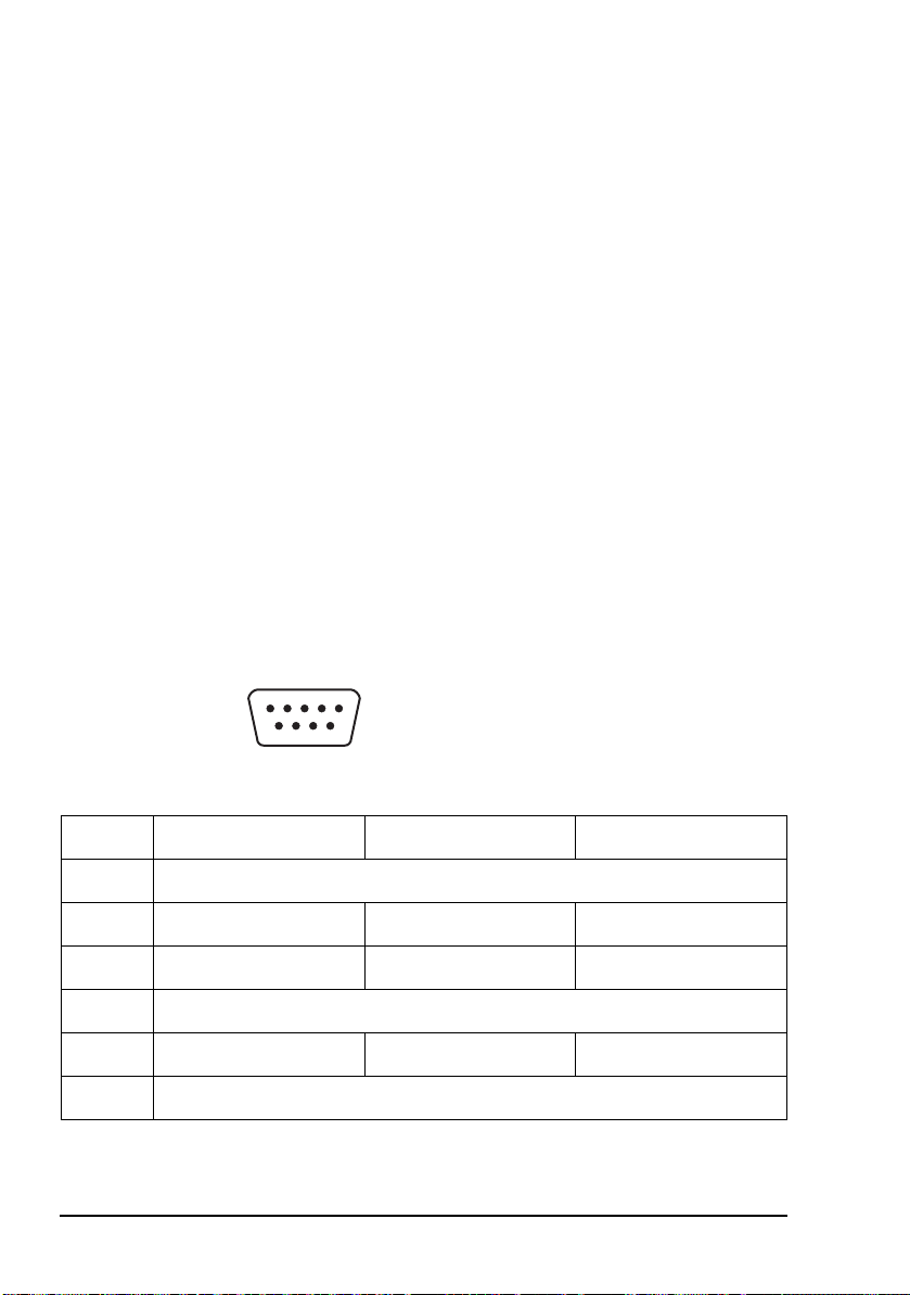
Connectors
15
96
Transceiver Control connector
The Transceiver Control connector is a 9-way, D-type male
connector on the rear panel of the 3112. It provides an
asynchronous, RS232, DTE, remote control interface to the
transceiver. The port is fully optically isolated.
The port settings are fixed as follows:
Baud rate 9600
Data bits 8
Parity Even
Stop bits 1
Flow control None
Figure 19: Front view of the Transceiver Control connector
Table 5: Pinouts for the Transceiver Control connector
Pin No. Function Input/Output Signal level
1N/C
2 Rx data Input RS232
3 Tx data Output RS232
4N/C
5 Signal ground 0 V
6–9 N/C
76 HF Data Modem 3112 User Guide
Page 87
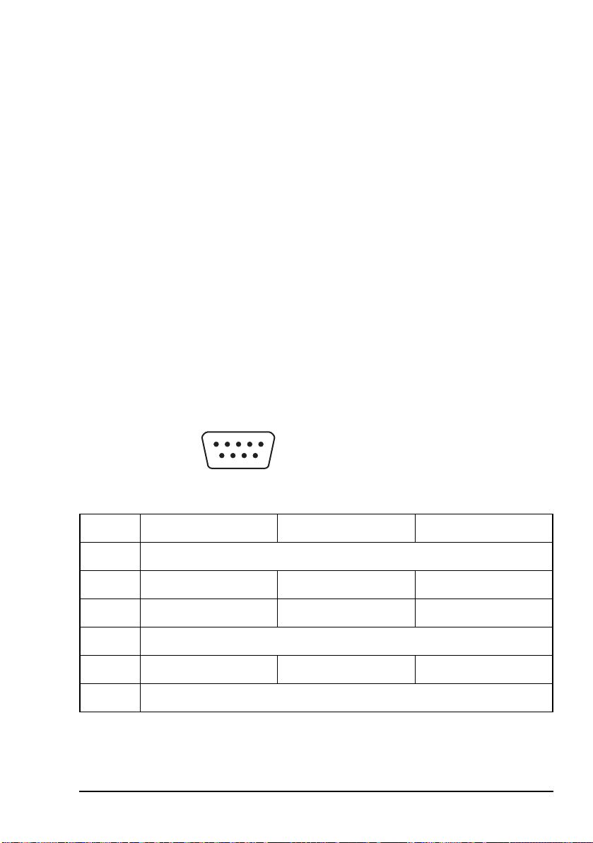
Modem Control connector
15
96
The Modem Control connector is a 9-way, D-type male
connector on the rear panel of the 3112. It provides an
asynchronous, RS232, DTE, remote control interface to the
modem. The port is fully optically isolated.
The port settings are fixed as follows:
Baud rate 9600
Data bits 8
Parity Even
Stop bits 1
Flow control None
Figure 20: Front view of the Modem Control connector
Connectors
Pin No. Function Input/Output Signal level
1N/C
2 Rx data Input RS232
3 Tx data Output RS232
4N/C
5 Signal ground 0 V
6–9 N/C
HF Data Modem 3112 User Guide 77
Table 6: Pinouts for the Modem Control connector
Page 88

Connectors
18
159
Transceiver connector
The Transceiver connector is a 15-way, D-type male
connector on the rear panel of the 3112. It provides the power,
data, and control connection between the modem and the
Codan HF transceiver.
Figure 21: Front view of the Transceiver connector
Table 7: Pinouts for the Transceiver connector
Pin No. Function Input/Output Signal level
1 Positive supply Input +12 V nominal supply
2
3 Rx data Input RS232
4 PTT return Output Opto-coupler emitter
5 Q line control line Output Open collector, 20 V
maximum
6600Ω balanced,
transformer isolated
Output –30 to +5 dBm audio,
software adjustable
audio –
7 PTT to key transceiver Output Opto-coupler, open
collector, 20 V
maximum
8600Ω balanced,
transformer isolated
Output –30 to +5 dBm audio,
software adjustable
audio +
9 Power and signal
10
78 HF Data Modem 3112 User Guide
ground
0V
Page 89

Table 7: Pinouts for the Transceiver connector (cont.)
Pin No. Function Input/Output Signal level
11 Spare line Input/Output Input:
12 Spare line Input/Output
VIL 0 to 0.8 V
VIH 2.4 to 20 V
Output:
Open collector,
20 V maximum
Connectors
13 600 Ω balanced,
transformer isolated
Input –30 to +3 dBm, AGC
controlled
audio –
14 Tx data Output RS232
15 600 Ω balanced,
transformer isolated
Input –30 to +3 dBm, AGC
controlled
audio +
HF Data Modem 3112 User Guide 79
Page 90

Connectors
113
1425
Sync/Async Data connector
The Sync/Async Data connector is a 25-way, D-type female
connector on the rear panel of the 3112. It provides a DCE
interface. The port settings can be configured as required for
your installation. This port is fully optically isolated.
In asynchronous mode, the connector passes data at rates up to
115 kbps. In synchronous mode, the connector passes data at
rates up to 9600 bps.
Figure 22: Front view of the Sync/Async Data connector
Table 8: Pinouts for the Sync/Async Data connector
Pin No. Function Input/Output Signal level
1 Frame ground 0 V
2 Tx data Input RS232
3 Rx data Output RS232
4 RTS Input RS232
5 CTS Output RS232
6 DSR Output RS232
7Ground 0V
8 DCD Output RS232
9–14 N/C
15 Transmitter clock Output RS232
16 N/C
80 HF Data Modem 3112 User Guide
Page 91

Table 8: Pinouts for the Sync/Async Data
connector (cont.)
Pin No. Function Input/Output Signal level
17 Receiver clock Output RS232
18–19 N/C
20 DTR Input RS232
21 N/C
22 Ring indicator Output RS232
23 N/C
Connectors
24 External transmitter
clock
25 N/C
Input RS232
HF Data Modem 3112 User Guide 81
Page 92

Connectors
18
LAN activity
(yellow)
Link status
(green)
Ethernet connector
The Ethernet connector provides a standard connection via a
straight or crossover CAT5 Ethernet cable. The connector has
two LEDs (see Figure 23).
The LAN activity LED flashes yellow when data is sent or
received through the connector.
The link status LED is steady green when there is a good
connection between the Ethernet connector and the
supporting switch.
The Ethernet port supports both 10 and 100 Mbps operation.
Figure 23: Front view of the Ethernet connector
Table 9: Pinouts for the Ethernet connector
Pin No. Function
1Tx +
2Tx –
3 Rx +
4N/C
5N/C
6 Rx –
7N/C
8N/C
82 HF Data Modem 3112 User Guide
Page 93

Appendix C—Specifications
Table 10: Specifications
Item Specification
Supply voltage 13.5 V DC nominal
10 to 15 V DC fully operational
Protection Reverse polarity and overvoltage protected to ±50 V DC
Supply current Backlight off: 250 mA @ 13.5 V DC
Backlight on: 350 mA @ 13.5 V DC
Operating
temperature
Relative humidity 0 to 95% non-condensing
Size 210 mm W × 240 mm D × 65 mm H
Weigh t 2 kg
Sealing IP64
Mounting Free standing
0 to +55°C
(8.3inW × 9.4inD × 2.6inH)
(includes allowance for rear connectors)
(4.4 lb)
Flange
Mobile mounting cradle
HF Data Modem 3112 User Guide 83
Page 94

Specifications
This page has been left blank intentionally.
84 HF Data Modem 3112 User Guide
Page 95

Appendix D—Factory-default
settings
The settings listed in Table 11 are loaded into the modem
when you restore the factory profile (see page 65, Resetting to
factory defaults). The factory settings for the default
waveform (STANAG 4539) are listed in Table 12 on page 86.
Table 11: Factory-default settings for the modem
Menu option Setting Value
Waveform STANAG 4539 (for default settings see
Table 12 on page 86)
Transceiver Audio Level –12 dBm
PTT Control Auto
Duplex Mode Half
Sync Settings Tx Clock Output
Polarity Normal
Async Settings Speed Mode Normal
Data Bits 8
Parity None
Stop Bits 1
Data Flow Ctrl CTS
Data Rate 115200 bps
Polarity Normal
RTS Mode Ignored
HF Data Modem 3112 User Guide 85
Page 96

Factory-default settings
Table 11: Factory-default settings for the modem
Menu option Setting Value
Test Loop Mode None
Tx Data Source External
Remote Control DHCP Off
Base Port 50000
Data Port Mode Async
Table 12: Factory-default settings for the STANAG 4539 waveform
Setting Value
Transmit Rate 9 600
Tx Interleaver Short
Rx Int. Set Short
TLC Blocks 7
Optional EOM On
Rx Limit 32767
86 HF Data Modem 3112 User Guide
Page 97

Appendix E—Compliance
This section contains the following topics:
Introduction (88)
European R&TTE Directive (89)
Electromagnetic compatibility and safety notices (90)
FCC compliance (92)
HF Data Modem 3112 User Guide 87
Page 98

Compliance
Introduction
This section describes how to ensure the 3112 HF Data
Modem complies with the European Electromagnetic
Compatibility Directive 89/336/EEC and the European Low
Voltage Directive 73/23/EEC as called up in the European
R&TTE Directive 1999/5/EC.
This section also contains the requirements for FCC
compliance.
88 HF Data Modem 3112 User Guide
Page 99

European R&TTE Directive
0191
0191
The 3112 HF Data Modem has been tested and complies with
the following standards and requirements (articles of the
R&TTE Directive):
• Article 3.1b: EN301 489-1
• Article 3.1b: EN301 489-15
• Article 3.1a: EN60950-1
Product marking and labelling
Any equipment supplied by Codan that satisfies these
requirements is identified by the , or
markings on the model label of the product.
Declaration of Conformity
The CE Declaration of Conformity for the product is listed on
page 99, Associated documents. This document can be made
available upon request to Codan or a Codan-authorised
supplier.
Compliance
HF Data Modem 3112 User Guide 89
Page 100

Compliance
Electromagnetic compatibility and safety notices
Electromagnetic compatibility
To ensure compliance with the EMC Directive is maintained,
you must:
1 Use standard shielded cables supplied from Codan
(where applicable).
1 For Ethernet connections, a ferrite bead (Codan part
number 39-79150-080) must be attached to the Ethernet
cable as close as possible to the Ethernet connector on
the modem.
1 Ensure the covers for the equipment are fitted correctly.
If it is necessary to remove the covers at
CAUTION
any stage, they must be refitted correctly
before using the equipment.
Electrical safety
To ensure compliance with the European Low Voltage
Directive is maintained, you must install and use the
3112 HF Data Modem in accordance with the instructions in
this guide.
90 HF Data Modem 3112 User Guide
 Loading...